EP2086004A1 - Member arranged in wafer storing container and method for manufacturing the member - Google Patents
Member arranged in wafer storing container and method for manufacturing the member Download PDFInfo
- Publication number
- EP2086004A1 EP2086004A1 EP07828067A EP07828067A EP2086004A1 EP 2086004 A1 EP2086004 A1 EP 2086004A1 EP 07828067 A EP07828067 A EP 07828067A EP 07828067 A EP07828067 A EP 07828067A EP 2086004 A1 EP2086004 A1 EP 2086004A1
- Authority
- EP
- European Patent Office
- Prior art keywords
- wafer
- sulfur
- case
- weight
- holding member
- Prior art date
- Legal status (The legal status is an assumption and is not a legal conclusion. Google has not performed a legal analysis and makes no representation as to the accuracy of the status listed.)
- Withdrawn
Links
Images


Classifications
-
- H—ELECTRICITY
- H10—SEMICONDUCTOR DEVICES; ELECTRIC SOLID-STATE DEVICES NOT OTHERWISE PROVIDED FOR
- H10P—GENERIC PROCESSES OR APPARATUS FOR THE MANUFACTURE OR TREATMENT OF DEVICES COVERED BY CLASS H10
- H10P72/00—Handling or holding of wafers, substrates or devices during manufacture or treatment thereof
- H10P72/10—Handling or holding of wafers, substrates or devices during manufacture or treatment thereof using carriers specially adapted therefor, e.g. front opening unified pods [FOUP]
- H10P72/19—Handling or holding of wafers, substrates or devices during manufacture or treatment thereof using carriers specially adapted therefor, e.g. front opening unified pods [FOUP] closed carriers
- H10P72/1902—Handling or holding of wafers, substrates or devices during manufacture or treatment thereof using carriers specially adapted therefor, e.g. front opening unified pods [FOUP] closed carriers specially adapted for a single substrate
-
- H—ELECTRICITY
- H10—SEMICONDUCTOR DEVICES; ELECTRIC SOLID-STATE DEVICES NOT OTHERWISE PROVIDED FOR
- H10P—GENERIC PROCESSES OR APPARATUS FOR THE MANUFACTURE OR TREATMENT OF DEVICES COVERED BY CLASS H10
- H10P72/00—Handling or holding of wafers, substrates or devices during manufacture or treatment thereof
- H10P72/10—Handling or holding of wafers, substrates or devices during manufacture or treatment thereof using carriers specially adapted therefor, e.g. front opening unified pods [FOUP]
- H10P72/19—Handling or holding of wafers, substrates or devices during manufacture or treatment thereof using carriers specially adapted therefor, e.g. front opening unified pods [FOUP] closed carriers
- H10P72/1911—Handling or holding of wafers, substrates or devices during manufacture or treatment thereof using carriers specially adapted therefor, e.g. front opening unified pods [FOUP] closed carriers characterised by materials, roughness, coatings or the like
-
- B—PERFORMING OPERATIONS; TRANSPORTING
- B29—WORKING OF PLASTICS; WORKING OF SUBSTANCES IN A PLASTIC STATE IN GENERAL
- B29C—SHAPING OR JOINING OF PLASTICS; SHAPING OF MATERIAL IN A PLASTIC STATE, NOT OTHERWISE PROVIDED FOR; AFTER-TREATMENT OF THE SHAPED PRODUCTS, e.g. REPAIRING
- B29C45/00—Injection moulding, i.e. forcing the required volume of moulding material through a nozzle into a closed mould; Apparatus therefor
- B29C45/0001—Injection moulding, i.e. forcing the required volume of moulding material through a nozzle into a closed mould; Apparatus therefor characterised by the choice of material
-
- B—PERFORMING OPERATIONS; TRANSPORTING
- B29—WORKING OF PLASTICS; WORKING OF SUBSTANCES IN A PLASTIC STATE IN GENERAL
- B29K—INDEXING SCHEME ASSOCIATED WITH SUBCLASSES B29B, B29C OR B29D, RELATING TO MOULDING MATERIALS OR TO MATERIALS FOR MOULDS, REINFORCEMENTS, FILLERS OR PREFORMED PARTS, e.g. INSERTS
- B29K2067/00—Use of polyesters or derivatives thereof, as moulding material
- B29K2067/006—PBT, i.e. polybutylene terephthalate
Definitions
- the present invention relates to a member installed in a case for storing a semiconductor wafer, in particular, to a wafer holding member.
- the present invention also relates to a method for producing a member installed in a case for storing a semiconductor wafer.
- the wafer in carrying a semiconductor wafer, the wafer is stored in a wafer storage case that supports and prevents damage on the wafer.
- a wafer storage case An example of such a wafer storage case is described in Patent Document 1.
- the wafer storage case disclosed in Patent Document 1 has a case main body with a circular barrel and a partition that divides the barrel into an upper portion and a lower portion, a lid that covers an upper opening of the case main body, and a wafer holding member disposed at the inner side of the lid as the lid is being attached to the case main body.
- the wafer holding member is configured to hold down the peripheral portion of the wafer stored in the case main body toward the partition of the case main body.
- the wafer storage case is formed by injection molding of a thermoplastic resin such as polypropylene, polyethylene, polycarbonate, or the like, for example.
- the wafer holding member is also formed by injection molding of a thermoplastic resin such as polypropylene, polyethylene, polycarbonate, or the like.
- a thermoplastic resin such as polypropylene, polyethylene, polycarbonate, or the like.
- a polybutylene terephthalate resin having excellent elasticity is suitable for the wafer holding member.
- Patent Document 1 Japanese Unexamined Patent Application Publication No. 2006-56573
- a sulfur-containing secondary antioxidant is usually added as an antioxidant in addition to a primary antioxidant.
- This sulfur-containing secondary antioxidant is commonly added since it not only prevents deterioration of the resin but also improves the soundness of processes during injection molding.
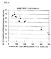
- the applicant of the present invention has studied the effect of sulfur gas on the wafer on the basis of the correlation between the sulfur gas concentration at the wafer surface and the photoluminescence (PL) intensity of the wafer.
- PL photoluminescence
- the sulfur gas concentration ( ⁇ E10 atoms/cm 2 ) at the wafer surface was varied and the PL intensities of these samples were measured.
- the correlation is shown in the graph of Fig. 5 .
- the sulfur gas concentration is preferably 200 (xE 10 atoms/cm 2 ) or less since, in general, the quality of the wafer is maintained at a PL intensity of 50 or higher.
- the PL intensity is measured by using a wafer after forming an AlGaIn thin film on a gallium arsenide substrate.
- the quantity of the sulfur gas generated inside the wafer storage case needs to be as small as possible to maintain the quality of the wafer inside the wafer storage case.
- sulfur-containing antioxidant added to a PBT resin generates sulfur gas, it is possible to add a high activity catalyst to prevent contamination of the wafer by the gas; however, addition of the high activity catalyst increases the cost.
- an object of the present invention is to provide a member installed in a wafer storage case in which contamination of the wafer by generation of sulfur gas is prevented, the process of injection molding is soundly carried out, and the wafer maintains good quality, and a method for producing the member.
- a member installed in a case for storing a wafer is characterized in that the member in the case is formed by injection molding of a polybutylene terephthalate (PBT) resin; the weight-average molecular weight (Mw) of the PBT resin is 15000 to 20000; and the weight of sulfur in a sulfur-containing secondary antioxidant added to the PBT resin is 0.1% or less of the weight of the PBT resin.
- PBT polybutylene terephthalate
- the member installed in the case for storing the wafer of the present invention may be formed by adding a sulfur-containing secondary antioxidant in a weight more than 0% but not more than 0.1% to the PBT resin or by adding no sulfur-containing secondary antioxidant.
- the resin viscosity during injection molding can be adjusted to a level suitable for injection molding without adding a sulfur-containing antioxidant since the weight-average molecular weight (Mw) of the PBT resin is at a relatively low level within the range of 15000 to 20000.
- Mw weight-average molecular weight
- the member installed in the wafer storage case can exhibit satisfactory quality. Therefore, good injection molded articles can be produced without substantial addition of the sulfur-containing antioxidant and generation of sulfur gas from the member can be nearly completely eliminated.
- the weight-average molecular weight (Mw) of the PBT resin is lower than 15000, the molecular weight is excessively low, and this may decrease the mechanical strength of the molded article. In contrast, in the case where the weight-average molecular weight (Mw) is higher than 20000, the viscosity is excessively high and the soundness of the injection molding process is not satisfactory.
- a method for producing a member installed in a case for storing a wafer according to the present invention is characterized by including injection molding a polybutylene terephthalate (PBT) resin having a weight-average molecular weight (Mw) of 15000 to 20000 so that the weight of sulfur in a sulfur-containing secondary antioxidant added to the PBT resin is 0.1% or less of the weight of the PBT resin.
- PBT polybutylene terephthalate
- the resin viscosity during injection molding can be adjusted to a level suitable for injection molding without adding a sulfur-containing antioxidant since the weight-average molecular weight (Mw) of the PBT resin is at a relatively low level within the range of 15000 to 20000.
- Mw weight-average molecular weight
- the member installed in the wafer storage case is preferably injection molded at a molding temperature of 230°C to 265°C.
- the fluidity of the molten resin is satisfactory without addition of the sulfur-containing antioxidant, thereby leading to satisfactory working.
- trace amounts of the sulfur-containing antioxidant may be added since the quantity of the generated sulfur gas is also small and the problem of contamination of the wafer by generated sulfur gas does not arise.
- Examples of the member installed in the wafer storage case include a wafer holding member and a sealing member such as a packing.
- the member installed in the wafer storage case of the present invention is preferably applied to a wafer holding member that contacts the wafer. Since the wafer holding member is stored in the case together with the wafer, it is desired that the holding member emit as little sulfur gas as possible. The present invention can meet this need.
- the resin viscosity during injection molding can be adjusted to a level suitable for injection molding without adding a sulfur-containing antioxidant since the weight-average molecular weight (Mw) of the PBT resin is at a relatively low level within the range of 15000 to 20000.
- Mw weight-average molecular weight
- Embodiments of the member installed in the wafer storage case of the present invention will now be described. An example in which the member installed in the wafer storage case is applied to a wafer holding member is described below.
- the wafer holding member is formed into a cross shape by injection molding of a polybutylene terephthalate (PBT) resin having a weight-average molecular weight (Mw) of 15000 or more and 20000 or less.
- PBT polybutylene terephthalate
- Mw weight-average molecular weight
- the wafer storage case 2 is formed by injection molding of a transparent polycarbonate resin.
- the wafer storage case 2 includes a bottomed cylindrical case main body 21 and a lid 22 that covers an upper opening of the case main body 21.
- the material of the wafer storage case 2 is not limited to polycarbonate, and other thermoplastic resins such as polypropylene, polyethylene, etc., and thermosetting resins such as epoxy resins, phenol resins, etc., may be used.
- the case main body 21 has a small diameter cylindrical portion 21a at the upper side and a large diameter cylindrical portion 21b at the lower side continuing from the small diameter cylindrical portion 21a.
- a partition 21c that partitions the small diameter cylindrical portion 21a from the large diameter cylindrical portion 21b is provided at a position where a step portion between the small diameter cylindrical portion 21a and the large diameter cylindrical portion 21b is formed.
- the partition 21c has a central portion recessed and spherically curved downward.
- a cylindrical projection 21d is formed on the center portion of the lower surface of the partition 21c.
- the lid 22 has a cylindrical portion 22a having an inner diameter larger than the outer diameter of the small diameter cylindrical portion 21a of the case main body 21 and a covering portion 22b covering one end of the cylindrical portion.
- the depth of the cylindrical portion 22a is the same as the height of the small diameter cylindrical portion 21a of the case main body.
- a projection 22c having the same size as the projection 21d formed on the partition 21c of the case main body is formed on the central portion of the lower surface of the covering portion 22b, i.e., the surface opposing the case main body 21.
- the projection 21d and 22c are arranged to fit into a fixing hole 11 provided in the wafer holding member 1.
- a ring-shaped protrusion 22d is formed at the upper surface side of the covering portion 22b of the lid 22 so as to be located at the same position as the end surface of the small diameter cylindrical portion 21a when the lid 22 is fitted to the small diameter cylindrical portion 21a of the case main body 21.
- the wafer holding member 1 has a cross shape in a plan view and includes a center connecting portion 12, in which the fixing hole 11 is formed at the center position, and four leg portions 13 respectively extending in four directions from the center connecting portion 12.
- the wafer holding member 1 is configured such that only the end portions of the leg portions 13 contact the flat component and that the center connecting portion 12 remains floating. As the center connecting portion 12 of the wafer holding member 1 is pressed downward to elastically deform the wafer holding member 1, the holding force works in the end portions of the leg portions 13.
- the fixing hole 11 formed in the center connecting portion 12 of the wafer holding member 1 is fitted to the projection 22c of the lid 22 so that the wafer holding member 1 can be fixed to the lid 22 without displacement.
- the wafer 3 In storing a wafer 3 in the wafer storage case 2, the wafer 3 is first placed on the partition 21c of the case main body 21. At this stage, the partition 21c is recessed downward and only the peripheral portion of the wafer 3 is in contact with the partition 21c.
- the lid 22 with the wafer holding member 1 is then fitted to the case main body 21.
- the wafer holding member 1 is pressed with the lid 22 toward the partition 21c of the case main body 21 so that the end portions of the leg portions 13 of the wafer holding member 1 abut against the peripheral portion of the wafer 3.
- the wafer holding member 1 fixes and immobilizes the wafer 3.
- the wafer holding member 1 installed in the wafer storage case 2 is made as follows.
- a polybutylene terephthalate (PBT) resin having a weight-average molecular weight (Mw) of 15000 to 20000 is used as the resin constituting the wafer holding member 1.
- the PBT resin is injection molded at a molding temperature of 230°C to 265°C without adding any sulfur-containing secondary antioxidant.
- the sulfur-containing secondary antioxidant is added so that the sulfur content in the sulfur-containing secondary antioxidant is 0.1% or less of the weight of the PBT resin.
- the resulting mixture is injection molded at a molding temperature of 230°C to 265°C so as to make the wafer holding member 1 shown in Figs. 1 and 2 .
- Injection molding is conducted by controlling the mold temperature in the range of 40°C to 80°C, the rotation speed of the screw of the injection molding machine in the range of 40 rpm to 200 rpm, the injection pressure in the range of 200 kg/cm 2 to 1500 kg/cm 2 , and the back pressure in the range of 0 kg/cm 2 to 100 kg/cm 2 .
- Additive agents other than the sulfur-containing secondary oxidant may be added to the polybutylene terephthalate (PBT) resin.
- PBT polybutylene terephthalate
- additive agents other than the sulfur-containing secondary oxidant include a primary antioxidant, a light stabilizer, and a hydrolytic inhibitor.
- Table II below shows measurement results of the variation in dimensional accuracy (rating is given as “small” or “large”) and the holding force (rating is given as “good” or “poor") of molded articles when the molded articles, i.e., the wafer holding members, shown in Fig. 1 were formed by injection molding of PBT resins having different weight-average molecular weights (Mw) and number-average molecular weights (Mn). Note that the injection molding process was conducted without adding the sulfur-containing secondary antioxidant.
- the injection conditions during the injection molding were a molding temperature of 250°C, a mold temperature of 60°C, a speed of rotation of a screw of an injection molding machine of 100 rpm, an injection pressure of 1000 kg/cm 2 , and a back pressure of 100 kg/cm 2 .
- the wafer holding force and the vertical displacement magnitude of the wafer holding member with time were compared between holding members (Samples 2-1 and 2-2) prepared by injection molding the PBT resin (without addition of sulfur-containing secondary antioxidant) of Sample 2 in Table II and holding members (Samples 2-3 and 2-4) prepared by injection molding a mixture of the PBT resin and a sulfur-containing secondary antioxidant, the sulfur content therein being 1% on a weight basis.
- the wafer holding force was determined by the vertical displacement magnitude of the wafer holding member relative to the load applied to the wafer holding member.
- the vertical displacement magnitude of the wafer holding member with time was determined by measuring the height of the holding member before storing the wafer in the case and then the height of the holding member 2 hours, 4 hours, 8 hours, and 16 hours after the wafer was stored in the case. The difference between the initial value and the observed values after these hours was calculated to determine the displacement magnitude.
- the vertical displacement magnitude of the wafer holding member with time is an indicator for evaluating the change in holding force with time.
- the measurement results of the wafer holding force are shown in Fig. 3
- the measurement results of the vertical displacement magnitude of the wafer holding member with time are shown in Fig. 4 .
- the results of the samples free of a sulfur-containing secondary antioxidant were substantially the same as the samples in which a sulfur-containing secondary antioxidant was added.
- the present invention is not limited to the embodiment and examples described above and covers all modifications and alternations within the scope of the claims and equivalents thereof.
- the present invention may be applied to a holding member for a storage case capable of storing a plurality of wafers instead of a wafer holding member for a storage case capable of storing wafer one by one described above.
- the present invention may be applied to a sealing member for each storage case.
- a member installed in a wafer storage case of the present invention and a method for producing the member are particularly suitable for use in a case for storing a silicone wafer.
Landscapes
- Container, Conveyance, Adherence, Positioning, Of Wafer (AREA)
- Packaging Frangible Articles (AREA)
- Packages (AREA)
Abstract
A high-quality member installed in a wafer storage case is provided in which the wafer is not contaminated by the generated sulfur gas and the injection molding process is satisfactorily carried out.
A member 1 installed in a case 2 for storing a wafer 3 is formed by injection molding a polybutylene terephthalate (PBT) resin. The PBT resin has a weight-average molecular weight (Mw) of 15000 to 20000. The member 1 installed in the wafer storage case is formed by injection molding so that the weight of sulfur in a sulfur-containing secondary antioxidant added to the PBT resin is 0.1% or less of the weight of the PBT resin.
Description
- The present invention relates to a member installed in a case for storing a semiconductor wafer, in particular, to a wafer holding member. The present invention also relates to a method for producing a member installed in a case for storing a semiconductor wafer.
- In general, in carrying a semiconductor wafer, the wafer is stored in a wafer storage case that supports and prevents damage on the wafer. An example of such a wafer storage case is described in
Patent Document 1. The wafer storage case disclosed inPatent Document 1 has a case main body with a circular barrel and a partition that divides the barrel into an upper portion and a lower portion, a lid that covers an upper opening of the case main body, and a wafer holding member disposed at the inner side of the lid as the lid is being attached to the case main body. The wafer holding member is configured to hold down the peripheral portion of the wafer stored in the case main body toward the partition of the case main body. - The wafer storage case is formed by injection molding of a thermoplastic resin such as polypropylene, polyethylene, polycarbonate, or the like, for example.
- The wafer holding member is also formed by injection molding of a thermoplastic resin such as polypropylene, polyethylene, polycarbonate, or the like. In particular, among thermoplastic resins, a polybutylene terephthalate resin having excellent elasticity is suitable for the wafer holding member.
- [Patent Document 1] Japanese Unexamined Patent Application Publication No.
2006-56573 - However, in forming the wafer holding member with the polybutylene terephthalate resin, a sulfur-containing secondary antioxidant is usually added as an antioxidant in addition to a primary antioxidant. This sulfur-containing secondary antioxidant is commonly added since it not only prevents deterioration of the resin but also improves the soundness of processes during injection molding.
- However, it has been found that sulfur in the sulfur-containing antioxidant becomes decomposed during injection molding. Once a large quantity of sulfur gas is generated from the wafer holding member, the wafer in contact with the wafer holding member becomes contaminated with the sulfur gas, thereby incurring a problem of degraded quality.
- Furthermore, the applicant of the present invention has studied the effect of sulfur gas on the wafer on the basis of the correlation between the sulfur gas concentration at the wafer surface and the photoluminescence (PL) intensity of the wafer.
-
[Table I] Sample No. Surface S concentration (×E10 atoms/cm2) PL intensity Sample A 53. 1 67. 1 Sample B 500. 0 20. 0 Sample C 136. 8 52. 6 Sample D 196. 2 50. 9 Sample E 404. 1 32. 1 Sample F 75. 8 69. 8 Sample G 85. 1 63. 6 Sample H 144. 4 59. 9 - As shown in Samples A to H in Table I, the sulfur gas concentration (×E10 atoms/cm2) at the wafer surface was varied and the PL intensities of these samples were measured. The correlation is shown in the graph of
Fig. 5 . As a result, it has been found from the results shown in Table I andFig. 5 that the sulfur gas concentration is preferably 200 (xE 10 atoms/cm2) or less since, in general, the quality of the wafer is maintained at a PL intensity of 50 or higher. The PL intensity is measured by using a wafer after forming an AlGaIn thin film on a gallium arsenide substrate. - As described above, the quantity of the sulfur gas generated inside the wafer storage case needs to be as small as possible to maintain the quality of the wafer inside the wafer storage case.
- If the sulfur-containing antioxidant added to a PBT resin generates sulfur gas, it is possible to add a high activity catalyst to prevent contamination of the wafer by the gas; however, addition of the high activity catalyst increases the cost.
- In view of the above, an object of the present invention is to provide a member installed in a wafer storage case in which contamination of the wafer by generation of sulfur gas is prevented, the process of injection molding is soundly carried out, and the wafer maintains good quality, and a method for producing the member.
- A member installed in a case for storing a wafer is characterized in that the member in the case is formed by injection molding of a polybutylene terephthalate (PBT) resin; the weight-average molecular weight (Mw) of the PBT resin is 15000 to 20000; and the weight of sulfur in a sulfur-containing secondary antioxidant added to the PBT resin is 0.1% or less of the weight of the PBT resin.
- The member installed in the case for storing the wafer of the present invention may be formed by adding a sulfur-containing secondary antioxidant in a weight more than 0% but not more than 0.1% to the PBT resin or by adding no sulfur-containing secondary antioxidant.
- The resin viscosity during injection molding can be adjusted to a level suitable for injection molding without adding a sulfur-containing antioxidant since the weight-average molecular weight (Mw) of the PBT resin is at a relatively low level within the range of 15000 to 20000. Thus, the member installed in the wafer storage case can exhibit satisfactory quality. Therefore, good injection molded articles can be produced without substantial addition of the sulfur-containing antioxidant and generation of sulfur gas from the member can be nearly completely eliminated.
- In the case where the weight-average molecular weight (Mw) of the PBT resin is lower than 15000, the molecular weight is excessively low, and this may decrease the mechanical strength of the molded article. In contrast, in the case where the weight-average molecular weight (Mw) is higher than 20000, the viscosity is excessively high and the soundness of the injection molding process is not satisfactory.
- A method for producing a member installed in a case for storing a wafer according to the present invention is characterized by including injection molding a polybutylene terephthalate (PBT) resin having a weight-average molecular weight (Mw) of 15000 to 20000 so that the weight of sulfur in a sulfur-containing secondary antioxidant added to the PBT resin is 0.1% or less of the weight of the PBT resin.
- According to the method of the present invention, as described above, the resin viscosity during injection molding can be adjusted to a level suitable for injection molding without adding a sulfur-containing antioxidant since the weight-average molecular weight (Mw) of the PBT resin is at a relatively low level within the range of 15000 to 20000. Thus, the workability is satisfactory. Therefore, injection molded can be performed satisfactorily without substantial addition of the sulfur-containing antioxidant and generation of sulfur gas from the member can be nearly completely eliminated.
- In particular, the member installed in the wafer storage case is preferably injection molded at a molding temperature of 230°C to 265°C.
- When the member is injection molded at such a temperature condition, the fluidity of the molten resin is satisfactory without addition of the sulfur-containing antioxidant, thereby leading to satisfactory working. Alternatively, trace amounts of the sulfur-containing antioxidant may be added since the quantity of the generated sulfur gas is also small and the problem of contamination of the wafer by generated sulfur gas does not arise.
- At a molding temperature lower than 230°C, the surface smoothness of the molded article obtained by injection molding is degraded. At a temperature exceeding 265°C, organic volatile compounds derived from other additive agents become decomposed into gas, which is not preferred.
- Examples of the member installed in the wafer storage case include a wafer holding member and a sealing member such as a packing. The member installed in the wafer storage case of the present invention is preferably applied to a wafer holding member that contacts the wafer. Since the wafer holding member is stored in the case together with the wafer, it is desired that the holding member emit as little sulfur gas as possible. The present invention can meet this need.
- The resin viscosity during injection molding can be adjusted to a level suitable for injection molding without adding a sulfur-containing antioxidant since the weight-average molecular weight (Mw) of the PBT resin is at a relatively low level within the range of 15000 to 20000. Thus, the process can be soundly carried out and the member installed in the wafer storage case can exhibit satisfactory quality. Therefore, good injection molded articles can be produced without substantial addition of the sulfur-containing antioxidant and generation of sulfur gas from the member can be nearly completely eliminated.
-
- [
Figure 1] Figure 1 is s plan view of a wafer storage case having a wafer holding member, which is a member installed in the wafer storage case according to the present invention. - [
Figure 2] Figure 2 is a vertical cross sectional view of a wafer storage case having a wafer holding member, which is a member installed in the wafer storage case according to the present invention. - [
Figure 3] Figure 3 is a graph showing the measurement results of holding force of the wafer holding member of the present invention. - [
Figure 4] Figure 4 is a graph showing the measurement results of vertical displacement magnitude of the wafer holding member of the present invention with time. - [
Figure 5] Figure 5 is a graph showing the correlation between the PL intensity and the sulfur gas concentration on the surface of the wafer. -
- 1 wafer holding member
- 11 fixing
hole 12center connecting portion 13 leg portions - 2 wafer storage case
- 21 case main body
- 21a small diameter
cylindrical portion 21b large diameter cylindrical portion -
21c partition 21d projection - 22 lid
- 22a
cylindrical portion 22b covering portion -
22c projection 22d ring-shaped protrusion - 3 wafer
- Embodiments of the member installed in the wafer storage case of the present invention will now be described. An example in which the member installed in the wafer storage case is applied to a wafer holding member is described below.
- The wafer holding member is formed into a cross shape by injection molding of a polybutylene terephthalate (PBT) resin having a weight-average molecular weight (Mw) of 15000 or more and 20000 or less. This
wafer holding member 1 is stored in awafer storage case 2, as shown inFigs. 1 and 2 . - The
wafer storage case 2 is formed by injection molding of a transparent polycarbonate resin. Thewafer storage case 2 includes a bottomed cylindrical casemain body 21 and alid 22 that covers an upper opening of the casemain body 21. The material of thewafer storage case 2 is not limited to polycarbonate, and other thermoplastic resins such as polypropylene, polyethylene, etc., and thermosetting resins such as epoxy resins, phenol resins, etc., may be used. - As shown in
Figs. 1 and 2 , the casemain body 21 has a small diametercylindrical portion 21a at the upper side and a large diametercylindrical portion 21b at the lower side continuing from the small diametercylindrical portion 21a. Apartition 21c that partitions the small diametercylindrical portion 21a from the large diametercylindrical portion 21b is provided at a position where a step portion between the small diametercylindrical portion 21a and the large diametercylindrical portion 21b is formed. Thepartition 21c has a central portion recessed and spherically curved downward. Acylindrical projection 21d is formed on the center portion of the lower surface of thepartition 21c. - The
lid 22 has acylindrical portion 22a having an inner diameter larger than the outer diameter of the small diametercylindrical portion 21a of the casemain body 21 and a coveringportion 22b covering one end of the cylindrical portion. The depth of thecylindrical portion 22a is the same as the height of the small diametercylindrical portion 21a of the case main body. Aprojection 22c having the same size as theprojection 21d formed on thepartition 21c of the case main body is formed on the central portion of the lower surface of the coveringportion 22b, i.e., the surface opposing the casemain body 21. Theprojection hole 11 provided in thewafer holding member 1. - Moreover, a ring-shaped
protrusion 22d is formed at the upper surface side of the coveringportion 22b of thelid 22 so as to be located at the same position as the end surface of the small diametercylindrical portion 21a when thelid 22 is fitted to the small diametercylindrical portion 21a of the casemain body 21. - The
wafer holding member 1 has a cross shape in a plan view and includes acenter connecting portion 12, in which the fixinghole 11 is formed at the center position, and fourleg portions 13 respectively extending in four directions from thecenter connecting portion 12. - The
wafer holding member 1 is configured such that only the end portions of theleg portions 13 contact the flat component and that thecenter connecting portion 12 remains floating. As thecenter connecting portion 12 of thewafer holding member 1 is pressed downward to elastically deform thewafer holding member 1, the holding force works in the end portions of theleg portions 13. - The fixing
hole 11 formed in thecenter connecting portion 12 of thewafer holding member 1 is fitted to theprojection 22c of thelid 22 so that thewafer holding member 1 can be fixed to thelid 22 without displacement. - In storing a
wafer 3 in thewafer storage case 2, thewafer 3 is first placed on thepartition 21c of the casemain body 21. At this stage, thepartition 21c is recessed downward and only the peripheral portion of thewafer 3 is in contact with thepartition 21c. - The
lid 22 with thewafer holding member 1 is then fitted to the casemain body 21. As thelid 22 is fitted to the casemain body 21, thewafer holding member 1 is pressed with thelid 22 toward thepartition 21c of the casemain body 21 so that the end portions of theleg portions 13 of thewafer holding member 1 abut against the peripheral portion of thewafer 3. As a result thewafer holding member 1 fixes and immobilizes thewafer 3. - The
wafer holding member 1 installed in thewafer storage case 2 is made as follows. - A polybutylene terephthalate (PBT) resin having a weight-average molecular weight (Mw) of 15000 to 20000 is used as the resin constituting the
wafer holding member 1. The PBT resin is injection molded at a molding temperature of 230°C to 265°C without adding any sulfur-containing secondary antioxidant. Alternatively, if a sulfur-containing secondary antioxidant is to be added to the PBT resin, the sulfur-containing secondary antioxidant is added so that the sulfur content in the sulfur-containing secondary antioxidant is 0.1% or less of the weight of the PBT resin. Then the resulting mixture is injection molded at a molding temperature of 230°C to 265°C so as to make thewafer holding member 1 shown inFigs. 1 and 2 . - Injection molding is conducted by controlling the mold temperature in the range of 40°C to 80°C, the rotation speed of the screw of the injection molding machine in the range of 40 rpm to 200 rpm, the injection pressure in the range of 200 kg/cm2 to 1500 kg/cm2, and the back pressure in the range of 0 kg/cm2 to 100 kg/cm2.
- Additive agents other than the sulfur-containing secondary oxidant may be added to the polybutylene terephthalate (PBT) resin. Examples thereof include a primary antioxidant, a light stabilizer, and a hydrolytic inhibitor.
- Table II below shows measurement results of the variation in dimensional accuracy (rating is given as "small" or "large") and the holding force (rating is given as "good" or "poor") of molded articles when the molded articles, i.e., the wafer holding members, shown in
Fig. 1 were formed by injection molding of PBT resins having different weight-average molecular weights (Mw) and number-average molecular weights (Mn). Note that the injection molding process was conducted without adding the sulfur-containing secondary antioxidant. - The injection conditions during the injection molding were a molding temperature of 250°C, a mold temperature of 60°C, a speed of rotation of a screw of an injection molding machine of 100 rpm, an injection pressure of 1000 kg/cm2, and a back pressure of 100 kg/cm2.
-
[Table II] Sample No. Weight-average molecular weight (Mw) Number-average molecular weight (Mn) Mw/Mn Variation in dimensional accuracy of molded articles Holding force Sample No. 1 16600 7500 2.2 Small Good Sample No. 2 16800 8000 2.1 Small Good Sample No. 3 17500 7300 2.2 Small Good Sample No. 4 17500 8000 2. 2 Small Good Sample No. 5 18900 7500 2.5 Small Good Sample No. 6 19600 8400 2.3 Small Good Sample No. 7 19800 8800 2.3 3 Small Good Sample No. 8 23700 10600 2.2 Large Poor Sample No. 9 28200 11000 2.6 Large Poor Sample No. 10 33000 11100 3 Large Poor Sample No. 11 35900 13200 2.7 Large Poor - As shown in Table II, the variation in dimension was small and the holding force was good in
Samples 1 to 7 in which a PBT resin having a weight-average molecular weight (Mw) of 15000 to 20000 was used. - The wafer holding force and the vertical displacement magnitude of the wafer holding member with time were compared between holding members (Samples 2-1 and 2-2) prepared by injection molding the PBT resin (without addition of sulfur-containing secondary antioxidant) of
Sample 2 in Table II and holding members (Samples 2-3 and 2-4) prepared by injection molding a mixture of the PBT resin and a sulfur-containing secondary antioxidant, the sulfur content therein being 1% on a weight basis. - No sulfur gas was generated from Samples 2-1 and 2-2 and the PL intensity of the wafers stored in these samples was 70 whereas the sulfur gas concentration at the surfaces of the wafers held in Samples 2-3 and 2-4 was 500 (×E10 atoms/cm2) and the PL intensity was 20.
- The wafer holding force was determined by the vertical displacement magnitude of the wafer holding member relative to the load applied to the wafer holding member.
- The vertical displacement magnitude of the wafer holding member with time was determined by measuring the height of the holding member before storing the wafer in the case and then the height of the holding
member 2 hours, 4 hours, 8 hours, and 16 hours after the wafer was stored in the case. The difference between the initial value and the observed values after these hours was calculated to determine the displacement magnitude. The vertical displacement magnitude of the wafer holding member with time is an indicator for evaluating the change in holding force with time. - The measurement results of the wafer holding force are shown in
Fig. 3 , and the measurement results of the vertical displacement magnitude of the wafer holding member with time are shown inFig. 4 . - As for the wafer holding force and the vertical displacement magnitude of the wafer holding member with time, the results of the samples free of a sulfur-containing secondary antioxidant were substantially the same as the samples in which a sulfur-containing secondary antioxidant was added.
- It should be understood that the present invention is not limited to the embodiment and examples described above and covers all modifications and alternations within the scope of the claims and equivalents thereof. For example, the present invention may be applied to a holding member for a storage case capable of storing a plurality of wafers instead of a wafer holding member for a storage case capable of storing wafer one by one described above. Moreover, the present invention may be applied to a sealing member for each storage case.
- A member installed in a wafer storage case of the present invention and a method for producing the member are particularly suitable for use in a case for storing a silicone wafer.
Claims (5)
- A member installed in a case for storing a wafer, characterized in that:the member in the case is formed by injection molding of a polybutylene terephthalate (PBT) resin;a weight-average molecular weight (Mw) of the PBT resin is 15000 to 20000; anda weight of sulfur in a sulfur-containing secondary antioxidant added to the PBT resin is 0.1% or less of the weight of the PBT resin.
- The member installed in the case for storing the wafer according to claim 1, characterized in that:the member installed in the case for storing the wafer is a wafer holding member.
- A method for producing a member installed in a case for storing a wafer, characterized by comprising:injection-molding a polybutylene terephthalate (PBT) resin having a weight-average molecular weight (Mw) of 15000 to 20000 so that the weight of sulfur in a sulfur-containing secondary antioxidant added to the PBT resin is 0.1% or less of the weight of the PBT resin.
- The method for producing the member installed in the case for storing the wafer according to claim 3, characterized in that the member installed in the case for storing the wafer is injection molded at a molding temperature of 230°C to 265°C.
- The method for producing the member installed in the case for storing the wafer according to claim 3 or 4, characterized in that the member installed in the case for storing the wafer is a wafer holding member.
Applications Claiming Priority (2)
| Application Number | Priority Date | Filing Date | Title |
|---|---|---|---|
| JP2006317309A JP2008130982A (en) | 2006-11-24 | 2006-11-24 | Member provided in wafer storage container and manufacturing method thereof |
| PCT/JP2007/001290 WO2008062564A1 (en) | 2006-11-24 | 2007-11-22 | Member arranged in wafer storing container and method for manufacturing the member |
Publications (1)
| Publication Number | Publication Date |
|---|---|
| EP2086004A1 true EP2086004A1 (en) | 2009-08-05 |
Family
ID=39429507
Family Applications (1)
| Application Number | Title | Priority Date | Filing Date |
|---|---|---|---|
| EP07828067A Withdrawn EP2086004A1 (en) | 2006-11-24 | 2007-11-22 | Member arranged in wafer storing container and method for manufacturing the member |
Country Status (5)
| Country | Link |
|---|---|
| US (1) | US20100222506A1 (en) |
| EP (1) | EP2086004A1 (en) |
| JP (1) | JP2008130982A (en) |
| TW (1) | TW200832589A (en) |
| WO (1) | WO2008062564A1 (en) |
Families Citing this family (2)
| Publication number | Priority date | Publication date | Assignee | Title |
|---|---|---|---|---|
| SG11201707411QA (en) * | 2015-04-10 | 2017-10-30 | Shinetsu Polymer Co | Substrate storage container |
| KR102673842B1 (en) * | 2021-10-27 | 2024-06-10 | (주)코스탯아이앤씨 | Electromagnetic interference shielding tray for accommodating semiconductor device and method of manufacturing the same |
Family Cites Families (13)
| Publication number | Priority date | Publication date | Assignee | Title |
|---|---|---|---|---|
| JPH08236605A (en) * | 1995-02-28 | 1996-09-13 | Komatsu Electron Metals Co Ltd | Semiconductor wafer storage case |
| JPH08250581A (en) * | 1995-03-08 | 1996-09-27 | Shin Etsu Polymer Co Ltd | Wafer container |
| JP3283743B2 (en) * | 1996-01-11 | 2002-05-20 | 帝人株式会社 | Silicon wafer carrier |
| JPH1174337A (en) * | 1997-08-28 | 1999-03-16 | Nippon Zeon Co Ltd | Thermoplastic container |
| EP0933199A1 (en) * | 1998-01-20 | 1999-08-04 | E.I. Du Pont De Nemours And Company | Low pigment content polyester film and process for making the same |
| JP2002179895A (en) * | 2000-12-15 | 2002-06-26 | Toyobo Co Ltd | Polyester resin composition |
| EP1429380A4 (en) * | 2001-08-28 | 2009-07-15 | Zeon Corp | CONTAINER FOR PRECISION SUBSTRATE |
| US6644477B2 (en) * | 2002-02-26 | 2003-11-11 | Entegris, Inc. | Wafer container cushion system |
| US7677394B2 (en) * | 2003-01-09 | 2010-03-16 | Brooks Automation, Inc. | Wafer shipping container |
| US7119141B2 (en) * | 2003-08-20 | 2006-10-10 | General Electric Company | Polyester molding composition |
| US7445810B2 (en) * | 2004-04-15 | 2008-11-04 | Hewlett-Packard Development Company, L.P. | Method of making a tantalum layer and apparatus using a tantalum layer |
| DE102004063912B4 (en) * | 2004-04-22 | 2007-09-20 | Siltronic Ag | Method for ready-to-ship packaging of semiconductor wafers |
| JP4624035B2 (en) * | 2004-08-20 | 2011-02-02 | 三甲株式会社 | Wafer transfer container |
-
2006
- 2006-11-24 JP JP2006317309A patent/JP2008130982A/en active Pending
-
2007
- 2007-11-22 EP EP07828067A patent/EP2086004A1/en not_active Withdrawn
- 2007-11-22 TW TW096144314A patent/TW200832589A/en unknown
- 2007-11-22 US US12/160,958 patent/US20100222506A1/en not_active Abandoned
- 2007-11-22 WO PCT/JP2007/001290 patent/WO2008062564A1/en not_active Ceased
Non-Patent Citations (1)
| Title |
|---|
| See references of WO2008062564A1 * |
Also Published As
| Publication number | Publication date |
|---|---|
| WO2008062564A1 (en) | 2008-05-29 |
| TW200832589A (en) | 2008-08-01 |
| US20100222506A1 (en) | 2010-09-02 |
| JP2008130982A (en) | 2008-06-05 |
Similar Documents
| Publication | Publication Date | Title |
|---|---|---|
| KR20110135862A (en) | Article with gasket having moisture transmission resistivity and method | |
| US8474626B2 (en) | FOUP and robotic flange thereof | |
| CN103262230B (en) | There is the chip container of a guiding element and seal | |
| KR20120037914A (en) | Substrate-storing container | |
| KR102090073B1 (en) | Base container with improved containment | |
| EP2086004A1 (en) | Member arranged in wafer storing container and method for manufacturing the member | |
| EP3239241A1 (en) | Resin composition, metal-resin composite, and preparation method and use thereof, and electronic product housing | |
| JP5888492B2 (en) | Substrate storage container | |
| EP0966052B1 (en) | Gasket, method of molding same, and cylindrical alkaline manganese dioxide cell using same | |
| CN106103298B (en) | tank for active agent | |
| JP5947555B2 (en) | Sealed battery and method for manufacturing the same | |
| EP3239242A1 (en) | Anti-yellowing composition, resin composition, metal-resin composite, preparation method and use thereof, and electronic product housing | |
| WO2015037176A1 (en) | Container for storing photomask blanks | |
| US20110020639A1 (en) | Plastic laminate and method for making the plastic laminate | |
| JP6353182B2 (en) | Sealed container and package | |
| JP2010013554A (en) | Thermoplastic polyester composition and manufacturing method thereof | |
| WO2022055850A1 (en) | Integrated tray and pallet system | |
| JP2000109792A (en) | Gasket material | |
| US9873218B2 (en) | Method of manufacturing resin sealing module, and resin sealing module | |
| JP7053911B2 (en) | Complex | |
| US20050077205A1 (en) | Tray with flat bottom reference surface | |
| FR3119985A1 (en) | Thermoformed coffin | |
| KR20080005378U (en) | Molding cup for sectional inspection of plate type sample | |
| JP2006070715A (en) | Cut valve | |
| JP2014500616A (en) | Front-open wafer container with minimal door deflection |
Legal Events
| Date | Code | Title | Description |
|---|---|---|---|
| PUAI | Public reference made under article 153(3) epc to a published international application that has entered the european phase |
Free format text: ORIGINAL CODE: 0009012 |
|
| 17P | Request for examination filed |
Effective date: 20080714 |
|
| AK | Designated contracting states |
Kind code of ref document: A1 Designated state(s): AT BE BG CH CY CZ DE DK EE ES FI FR GB GR HU IE IS IT LI LT LU LV MC MT NL PL PT RO SE SI SK TR |
|
| DAX | Request for extension of the european patent (deleted) | ||
| STAA | Information on the status of an ep patent application or granted ep patent |
Free format text: STATUS: THE APPLICATION IS DEEMED TO BE WITHDRAWN |
|
| 18D | Application deemed to be withdrawn |
Effective date: 20140603 |