EP2085847A1 - Servo motor control system - Google Patents
Servo motor control system Download PDFInfo
- Publication number
- EP2085847A1 EP2085847A1 EP08168211A EP08168211A EP2085847A1 EP 2085847 A1 EP2085847 A1 EP 2085847A1 EP 08168211 A EP08168211 A EP 08168211A EP 08168211 A EP08168211 A EP 08168211A EP 2085847 A1 EP2085847 A1 EP 2085847A1
- Authority
- EP
- European Patent Office
- Prior art keywords
- current command
- servo
- serial bus
- motor
- value
- Prior art date
- Legal status (The legal status is an assumption and is not a legal conclusion. Google has not performed a legal analysis and makes no representation as to the accuracy of the status listed.)
- Granted
Links
Images




Classifications
-
- G—PHYSICS
- G05—CONTROLLING; REGULATING
- G05B—CONTROL OR REGULATING SYSTEMS IN GENERAL; FUNCTIONAL ELEMENTS OF SUCH SYSTEMS; MONITORING OR TESTING ARRANGEMENTS FOR SUCH SYSTEMS OR ELEMENTS
- G05B19/00—Program-control systems
- G05B19/02—Program-control systems electric
- G05B19/18—Numerical control [NC], i.e. automatically operating machines, in particular machine tools, e.g. in a manufacturing environment, so as to execute positioning, movement or co-ordinated operations by means of program data in numerical form
- G05B19/414—Structure of the control system, e.g. common controller or multiprocessor systems, interface to servo, programmable interface controller
-
- G—PHYSICS
- G05—CONTROLLING; REGULATING
- G05B—CONTROL OR REGULATING SYSTEMS IN GENERAL; FUNCTIONAL ELEMENTS OF SUCH SYSTEMS; MONITORING OR TESTING ARRANGEMENTS FOR SUCH SYSTEMS OR ELEMENTS
- G05B2219/00—Program-control systems
- G05B2219/30—Nc systems
- G05B2219/34—Director, elements to supervisory
- G05B2219/34221—Computer delivers control pulses from table directly to motors
-
- G—PHYSICS
- G05—CONTROLLING; REGULATING
- G05B—CONTROL OR REGULATING SYSTEMS IN GENERAL; FUNCTIONAL ELEMENTS OF SUCH SYSTEMS; MONITORING OR TESTING ARRANGEMENTS FOR SUCH SYSTEMS OR ELEMENTS
- G05B2219/00—Program-control systems
- G05B2219/30—Nc systems
- G05B2219/34—Director, elements to supervisory
- G05B2219/34434—Separate power controller for drive, servodrive, one per axis, connected to cnc
-
- G—PHYSICS
- G05—CONTROLLING; REGULATING
- G05B—CONTROL OR REGULATING SYSTEMS IN GENERAL; FUNCTIONAL ELEMENTS OF SUCH SYSTEMS; MONITORING OR TESTING ARRANGEMENTS FOR SUCH SYSTEMS OR ELEMENTS
- G05B2219/00—Program-control systems
- G05B2219/30—Nc systems
- G05B2219/35—Nc in input of data, input till input file format
- G05B2219/35563—Use of conversion tables
-
- G—PHYSICS
- G05—CONTROLLING; REGULATING
- G05B—CONTROL OR REGULATING SYSTEMS IN GENERAL; FUNCTIONAL ELEMENTS OF SUCH SYSTEMS; MONITORING OR TESTING ARRANGEMENTS FOR SUCH SYSTEMS OR ELEMENTS
- G05B2219/00—Program-control systems
- G05B2219/30—Nc systems
- G05B2219/36—Nc in input of data, input key till input tape
- G05B2219/36502—Ram for variable servo data, rom for fixed servo routine
-
- G—PHYSICS
- G05—CONTROLLING; REGULATING
- G05B—CONTROL OR REGULATING SYSTEMS IN GENERAL; FUNCTIONAL ELEMENTS OF SUCH SYSTEMS; MONITORING OR TESTING ARRANGEMENTS FOR SUCH SYSTEMS OR ELEMENTS
- G05B2219/00—Program-control systems
- G05B2219/30—Nc systems
- G05B2219/41—Servomotor, servo controller till figures
- G05B2219/41002—Servo amplifier
-
- G—PHYSICS
- G05—CONTROLLING; REGULATING
- G05B—CONTROL OR REGULATING SYSTEMS IN GENERAL; FUNCTIONAL ELEMENTS OF SUCH SYSTEMS; MONITORING OR TESTING ARRANGEMENTS FOR SUCH SYSTEMS OR ELEMENTS
- G05B2219/00—Program-control systems
- G05B2219/30—Nc systems
- G05B2219/41—Servomotor, servo controller till figures
- G05B2219/41003—Control power amplifier with data on data bus
-
- G—PHYSICS
- G05—CONTROLLING; REGULATING
- G05B—CONTROL OR REGULATING SYSTEMS IN GENERAL; FUNCTIONAL ELEMENTS OF SUCH SYSTEMS; MONITORING OR TESTING ARRANGEMENTS FOR SUCH SYSTEMS OR ELEMENTS
- G05B2219/00—Program-control systems
- G05B2219/30—Nc systems
- G05B2219/41—Servomotor, servo controller till figures
- G05B2219/41206—Lookup table, memory with certain relationships
-
- G—PHYSICS
- G05—CONTROLLING; REGULATING
- G05B—CONTROL OR REGULATING SYSTEMS IN GENERAL; FUNCTIONAL ELEMENTS OF SUCH SYSTEMS; MONITORING OR TESTING ARRANGEMENTS FOR SUCH SYSTEMS OR ELEMENTS
- G05B2219/00—Program-control systems
- G05B2219/30—Nc systems
- G05B2219/41—Servomotor, servo controller till figures
- G05B2219/41213—Lookup table for load, motor torque as function of actual position
-
- G—PHYSICS
- G05—CONTROLLING; REGULATING
- G05B—CONTROL OR REGULATING SYSTEMS IN GENERAL; FUNCTIONAL ELEMENTS OF SUCH SYSTEMS; MONITORING OR TESTING ARRANGEMENTS FOR SUCH SYSTEMS OR ELEMENTS
- G05B2219/00—Program-control systems
- G05B2219/30—Nc systems
- G05B2219/41—Servomotor, servo controller till figures
- G05B2219/41214—Lookup table for current as function of actual position
-
- G—PHYSICS
- G05—CONTROLLING; REGULATING
- G05B—CONTROL OR REGULATING SYSTEMS IN GENERAL; FUNCTIONAL ELEMENTS OF SUCH SYSTEMS; MONITORING OR TESTING ARRANGEMENTS FOR SUCH SYSTEMS OR ELEMENTS
- G05B2219/00—Program-control systems
- G05B2219/30—Nc systems
- G05B2219/43—Speed, acceleration, deceleration control ADC
- G05B2219/43097—Table, rom, ram speed table
Definitions
- the present invention relates to a servo motor control system that has, in a controller, a serial bus control circuit having a function of sending a current command in a plurality of different control modes to servo amplifiers for driving a servo motor.
- Driving and controlling a large-capacity motor requires a large-capacity inverter unit.
- acquisition of a large-capacity inverter unit is difficult because of constraints introduced by its components. Accordingly, a plurality of small-capacity inverter units are connected in parallel to obtain a large capacity required to drive and control a large-capacity motor.
- a motor control unit When a motor control unit supplies a motor driving command to each of the plurality of small-capacity inverter units connected to drive the motor, the motor control unit needs to generate as many motor driving commands as the inverter units. In this case, a plurality of motor driving command generation units are exclusively used to drive a motor. As a result, when the motor control unit drives another motor in addition to the above one, a certain number of motor driving command generation units for driving the other motor are further required, thereby limiting the total number of motors that can be driven.
- a motor control system that controls a plurality of inverter units using one motor driving command from a motor control unit and thereby drives one large-capacity motor is disclosed in, for example, Japanese Patent Application Laid-Open No. 2005-86918 . This motor control system will be described with reference to FIGs. 7A and 7B .
- a motor driving command which is created by a motor control unit 20 and sent through a serial bus 24 from the motor control unit 20, is supplied through a relay unit 21 to a plurality of inverter units 22a to 22d in parallel.
- Each of the plurality of inverter units 22a to 22d is controlled by the same (common) motor driving command and drives a motor 23.
- the motor control unit 20 can control the plurality of inverter units 22a to 22d using only one motor driving command generation unit. Accordingly, when the motor control unit 20 drives one or more other motors in addition to the motor 23 above, it is enough to add one or more motor driving command generation units and the addition is not so difficult.
- the relay unit 21 in FIG. 7A has a receiver circuit 21a, a setting circuit 21b, a computation circuit 21c, and a plurality of driver circuits 21d1 to 21dn as shown in detail in FIG. 7B .
- the plurality of driver circuits 21d1 to 21dn correspond to the plurality of inverter units 22a to 22d, respectively.
- the motor driving command (torque command) output as parallel data from the motor control unit 20 is received by the receiver circuit 21a of the relay unit 21 and input to the computation circuit 21c.
- the computation circuit 21c generates the motor driving command for the plurality of inverter units 22a to 22d.
- the generated motor driving command is simultaneously output as parallel data from the computation circuit 21c to the plurality of inverter units 22a to 22d through the plurality of driver circuits 21d1 to 21dn.
- the motor control system in FIG. 7A has the relay unit 21 (see FIG. 7B ) on the serial bus 24 that connects the motor control unit 20 and the motor 23. Therefore, a unit for controlling the motor 23 becomes complicated, making downsizing difficult.
- a command signal for the motor 23 is received by the relay unit 21 as serial data and, based on the received data, the command signal for the motor 23 is created, so response delay is caused.
- An object of the present invention is to provide a servo motor control system that has, in a serial bus control circuit in a numerical controller, a function of sending a current command or a torque command to a plurality of servo amplifiers for driving motors in a plurality of different control modes.
- the present invention relates to a servo motor control system in which a controller and a plurality of servo amplifiers are connected through a serial bus, a torque command or a current command for each of motors, generated by the controller, is sent to the plurality of servo amplifiers through the serial bus, and the plurality of servo amplifiers drive the motors based on the received torque command or current command.
- This servo motor control system can select, for each servo amplifier, a first mode, in which an arbitrary current command generated by the above controller is sent through the serial bus to a plurality of servo amplifiers specified so that the plurality of servo amplifiers specified can drive one or more motors based on the same current command received, or a second mode, in which each a plurality of current commands generated by the controller is sent through the serial bus to a corresponding servo amplifier so that the servo amplifier can drive a corresponding motor based on a corresponding current command.
- the above structure of the present invention eliminates the need for the relay unit on the serial bus, thereby enabling the downsizing and simplification of the unit.
- command information for a plurality of motors is processed before it passes through the serial bus, so no processing delay is caused.
- FIG. 1 illustrates a servo control system in which a serial bus control circuit 4 in a numerical controller 1 is placed in a mode in which data is read repeatedly from a current command register 3-1 and sent to two particular servo amplifiers 5-1 and 5-2.
- a digital signal processor (DPS) 2 calculates current command values (torque command values) for servo amplifiers 5-1, 5-2, and 5-3 to control the position, speed, and current of each servo motor using servo control software.
- the calculated current command values are stored in current command registers 3-1, 3-2, and 3-3, respectively, in a normal control mode described later.
- the current command registers 3-1, 3-2, and 3-3 are provided in association with the servo amplifiers 5-1, 5-2, 5-3, respectively.
- the serial bus control circuit 4 reads out the current command values stored in the current command registers 3-1, 3-2, and 3-3, converts the read current command values from parallel signals to serial signals, and then gives the converted signals to the servo amplifiers 5-1, 5-2, 5-3 through a serial bus 6.
- Tandem control by a first motor (not shown) connected to the servo amplifier 5-1 and a second motor (not shown) connected to the servo amplifier 5-2 will be considered below.
- the tandem control is a method of using a plurality of motors to drive a large movable member which would be difficult to accelerate or decelerate by one motor, through a current command generated by a numerical controller. In the tandem control, the same (common) current command value is given to the servo amplifiers 5-1 and 5-2.
- the DSP 2 In a normal control mode in which the same current command value is stored in the current register 3-1 for the servo amplifier 5-1 and the current register 3-2 for the servo amplifier 5-2, the DSP 2 needs to calculate the current command value twice, thereby consuming its processing power unnecessarily.
- the servo control system of the present invention places the numerical controller in a tandem control mode described below instead of the normal control mode above, thereby carrying out a tandem control.
- the current command value for the servo amplifier 5-2 is not stored (is stored in the normal control mode) in the current command register 3-2 in FIG. 1 .
- FIG. 2A indicates the correspondence between the current command registers 3-1 to 3-3 and the servo amplifiers 5-1 to 5-3 connected through the serial bus control circuit 4 in the normal control mode.
- a current command value for the servo amplifier 5-1 is stored in the current command register 3-1
- a current command value for the servo amplifier 5-2 is stored in the current command register 3-2
- a current command value for the servo amplifier 5-3 is stored in the current command register 3-3.
- FIG. 2B indicates the correspondence between the current command registers 3-1 to 3-3 and the servo amplifiers 5-1 to 5-3 connected through the serial bus control circuit 4 in the tandem control mode.
- a current command value for the servo amplifier 5-1 is stored in the current command register 3-1
- a current command value for the servo amplifier 5-2 is also stored in command register 3-1
- a current command value for the current the servo amplifier 5-3 is stored in the current command register 3-3.
- the current command register 3-2 is not used.
- the number of current command registers and servo amplifiers is assumed to be three in FIGs. 1 , 2A, and 2B , but the number is not limited to 3.
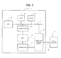
- FIG. 3 is a block diagram showing an example of the numerical controller of the servo control system of the present invention.
- the numerical controller 1 comprises a processor (CPU) 10, a DSP 2, a first common RAM 3, a serial bus control circuit 4, an SRAM 8, a ROM 9, and a second common RAM 11.
- the CPU 10 can access the DSP 2, the serial bus control circuit 4, the SRAM 8, the ROM 9, and the second common RAM 11 through a bus 7.
- the CPU 10 sends data to or receives data from the DPS 2 through the second common RAM 11.
- the DSP 2 reads out the movement amount from the second common RAM 11 and, based on the read movement amount, calculates the current command value for each servo motor.
- the current command values calculated by the DSP 2 are written to current command registers in the first common RAM 3.
- the serial bus control circuit 4 reads out the current command values from the current command registers in the first common RAM 3 and gives the read current command values to the servo amplifiers 5 (servo amplifiers 5-1 to 5-3) through the serial bus 6.
- the serial bus control circuit 4 reads out, a plurality of times (for example, twice), the current command value in one (for example, the current command register 3-1) of a plurality of current command registers in the first common RAM 3 by setting a parameter, sends the read value to a plurality of servo amplifiers (for example, the servo amplifiers 5-1 and 5-2), and drives a plurality of servo motors based on the same current command value.
- the serial bus control circuit 4 reads out once each of the current command values in the plurality of current command registers 3-1, 3-2, and 3-3 in the first common RAM 3, sends each of them to the corresponding one of the servo amplifier 5-1, 5-2, and 5-3, and drives the corresponding motor based on the current command value.
- FIG. 4 is a schematic block diagram showing the serial bus control circuit 4 of the servo control system of the present invention, the serial bus control circuit being placed in the tandem control mode.
- the serial bus control circuit 4 has an address table 4a, a conversion table 4b, a selector 4c, a transmission control circuit 4d, an up-counter 4e, a parallel/serial conversion circuit 4f, and an address transmission circuit 4g.
- the address table 4a stores addresses 4a1, 4a2 ... of the servo amplifiers 5-1, 5-2 ....
- the first common RAM 3 includes the current command registers 3-1, 3-2 ... that correspond to the addresses 4a1, 4a2 ... of the servo amplifiers 5-1, 5-2 ... set in the address table 4a.
- the conversion table 4b indicates the correspondence between servo amplifiers 5-1, 5-2 ... 5-n ... 5-N and current command registers 3-1, 3-2 ... 3-m ... 3-N.
- the conversion table 4b can be rewritten by a command from the CPU 10 to change the correspondence between the current command register 3-1, 3-2 ... and the servo amplifiers 5-1, 5-2 ....
- the conversion table 4b can also be rewritten to switch from the tandem control mode in FIG. 4 to the normal control mode in FIG. 5 .
- the transmission control circuit 4d increments the output value of the up-counter 4e by 1.
- the up-counter 4e outputs a count value "n" to the conversion table 4b.
- the conversion table 4b outputs "m” corresponding to "n” input from the up-counter 4e to selector 4c based on the correspondence (n-to-m conversion) shown in the table.
- the selector 4c selects the address 4am of the m-th servo amplifier (servo amplifier 5-m) from the address table 4a according to "m" received from the conversion table 4b and then outputs the selected address 4am to the first common RAM 3 through the address transmission circuit 4g.
- the first common RAM 3 outputs the register data in the current command register 3-m that corresponds to the address 4am of the servo amplifier 5-m received from the address transmission circuit 4g to the parallel/serial conversion circuit 4f.
- the register data which is a current command value calculated by the DSP 2, is parallel data.
- the parallel/serial conversion circuit 4f receives current command data from the first common RAM 3 and "n" output from the up-counter 4e.
- the output value "n" from the up-counter 4e is used to identify a servo amplifier (the servo amplifier 5-n is identified).
- the parallel/serial conversion circuit 4f converts the register data in the current command register 3-m from parallel data to serial data.
- the parallel/serial conversion circuit 4f also gives a pair of "n" for identifying a servo amplifier and the current command data stored in the current command register 3-m to the identified servo amplifier 5-n as serial data (for example, a packet signal).
- the servo amplifier 5-n that received the packet signal recognizes that the current command data stored in the current command register 3-m is a command sent to its own.
- FIG. 6 is a flowchart showing an example of the algorithm executed by the serial bus control circuit 4 of the servo control system of the present invention.
- the conversion table 4b outputs the "m” value corresponding to an input "n” value to the selector 4c according to the correspondence between "n” and "m” in the table (step S102).
- the selector 4c extracts the address 4am of the m-th servo amplifier 5-m from the address table 4a and sends it to the address transmission circuit 4g (step S103).
- the address transmission circuit 4g sends the address 4am of the servo amplifier 5-m received from the selector 4c to the first common RAM 3 (step S104).
- the first common RAM 3 sends the register data in the current command register 3-m corresponding to the address 4am received from the address transmission circuit 4g to the parallel/serial conversion circuit 4f of the serial bus control circuit 4 (step S105).
- the parallel/serial conversion circuit 4f converts the register data in the current command register 3-m received from the first common RAM 3 from parallel data to serial data (step S106) and gives the serial data to the (n-th) servo amplifier 5-n corresponding to "n" output from the up-counter 4e (step S107).
- step S108 Whether the value "n" of the up-counter 4e reaches N (maximum value of "n") is determined. When it reaches N (YES in step S108), the sequence is finished. When it does not reach N (NO in step S108), the value "n" of the up-counter 4e is incremented by 1 (step S109), the sequence returns to step S101 and the processing is continued.
- current command values are use as command values for servo amplifiers that drives the motor, but torque command values may also be used.
Landscapes
- Engineering & Computer Science (AREA)
- Human Computer Interaction (AREA)
- Manufacturing & Machinery (AREA)
- Physics & Mathematics (AREA)
- General Physics & Mathematics (AREA)
- Automation & Control Theory (AREA)
- Control Of Multiple Motors (AREA)
- Control Of Electric Motors In General (AREA)
- Control Of Ac Motors In General (AREA)
- Numerical Control (AREA)
Abstract
Description
- The present invention relates to a servo motor control system that has, in a controller, a serial bus control circuit having a function of sending a current command in a plurality of different control modes to servo amplifiers for driving a servo motor.
- Driving and controlling a large-capacity motor requires a large-capacity inverter unit. However, acquisition of a large-capacity inverter unit is difficult because of constraints introduced by its components. Accordingly, a plurality of small-capacity inverter units are connected in parallel to obtain a large capacity required to drive and control a large-capacity motor.
- When a motor control unit supplies a motor driving command to each of the plurality of small-capacity inverter units connected to drive the motor, the motor control unit needs to generate as many motor driving commands as the inverter units. In this case, a plurality of motor driving command generation units are exclusively used to drive a motor. As a result, when the motor control unit drives another motor in addition to the above one, a certain number of motor driving command generation units for driving the other motor are further required, thereby limiting the total number of motors that can be driven.
- A motor control system that controls a plurality of inverter units using one motor driving command from a motor control unit and thereby drives one large-capacity motor is disclosed in, for example, Japanese Patent Application Laid-Open No.
2005-86918 FIGs. 7A and 7B . - A motor driving command, which is created by a
motor control unit 20 and sent through aserial bus 24 from themotor control unit 20, is supplied through arelay unit 21 to a plurality ofinverter units 22a to 22d in parallel. Each of the plurality ofinverter units 22a to 22d is controlled by the same (common) motor driving command and drives amotor 23. As described above, themotor control unit 20 can control the plurality ofinverter units 22a to 22d using only one motor driving command generation unit. Accordingly, when themotor control unit 20 drives one or more other motors in addition to themotor 23 above, it is enough to add one or more motor driving command generation units and the addition is not so difficult. - The
relay unit 21 inFIG. 7A has areceiver circuit 21a, asetting circuit 21b, acomputation circuit 21c, and a plurality of driver circuits 21d1 to 21dn as shown in detail inFIG. 7B . The plurality of driver circuits 21d1 to 21dn correspond to the plurality ofinverter units 22a to 22d, respectively. The motor driving command (torque command) output as parallel data from themotor control unit 20 is received by thereceiver circuit 21a of therelay unit 21 and input to thecomputation circuit 21c. Thecomputation circuit 21c generates the motor driving command for the plurality ofinverter units 22a to 22d. The generated motor driving command is simultaneously output as parallel data from thecomputation circuit 21c to the plurality ofinverter units 22a to 22d through the plurality of driver circuits 21d1 to 21dn. - The motor control system in
FIG. 7A has the relay unit 21 (seeFIG. 7B ) on theserial bus 24 that connects themotor control unit 20 and themotor 23. Therefore, a unit for controlling themotor 23 becomes complicated, making downsizing difficult. In addition, a command signal for themotor 23 is received by therelay unit 21 as serial data and, based on the received data, the command signal for themotor 23 is created, so response delay is caused. - An object of the present invention is to provide a servo motor control system that has, in a serial bus control circuit in a numerical controller, a function of sending a current command or a torque command to a plurality of servo amplifiers for driving motors in a plurality of different control modes.
- The present invention relates to a servo motor control system in which a controller and a plurality of servo amplifiers are connected through a serial bus, a torque command or a current command for each of motors, generated by the controller, is sent to the plurality of servo amplifiers through the serial bus, and the plurality of servo amplifiers drive the motors based on the received torque command or current command.
- This servo motor control system can select, for each servo amplifier, a first mode, in which an arbitrary current command generated by the above controller is sent through the serial bus to a plurality of servo amplifiers specified so that the plurality of servo amplifiers specified can drive one or more motors based on the same current command received, or a second mode, in which each a plurality of current commands generated by the controller is sent through the serial bus to a corresponding servo amplifier so that the servo amplifier can drive a corresponding motor based on a corresponding current command.
- The above structure of the present invention eliminates the need for the relay unit on the serial bus, thereby enabling the downsizing and simplification of the unit. In addition, command information for a plurality of motors is processed before it passes through the serial bus, so no processing delay is caused.
- The purposes and advantages of the present invention, including those described above, will be clarified by reference to the attached drawings in combination with the description of the embodiment presented below. Of these drawings:
-
FIG. 1 illustrates a servo control system in which a serial bus control circuit of a numerical controller is placed in a mode in which data is read repeatedly from a current command register and sent to two particular servo amplifiers. -
FIG. 2A indicates the correspondence between current command registers and servo amplifiers connected through the serial bus control circuit in a normal control mode. -
FIG. 2B indicates the correspondence between the current command registers and the servo amplifiers connected through the serial bus control circuit placed in a tandem control mode. -
FIG. 3 is a block diagram showing an example of the numerical controller of the servo control system of the present invention. -
FIG. 4 is a schematic block diagram showing the serial bus control circuit of the numerical controller inFIG. 3 , the serial bus control circuit being placed in a first control mode (tandem control mode). -
FIG. 5 is a schematic block diagram showing the serial bus control circuit of the numerical controller inFIG. 3 , the serial bus control circuit being placed in a second control mode (normal control mode). -
FIG. 6 is a flowchart showing an example of the algorithm executed by the serial bus control circuit of the servo control system of the present invention. -
FIG. 7A is a block diagram showing an example of the motor control system in the prior art that controls a plurality of inverter units with one motor driving command from the motor control unit and thereby drives one large-capacity motor. -
FIG. 7B is a block diagram showing a relay unit of the motor control system inFIG. 7A . -
FIG. 1 illustrates a servo control system in which a serialbus control circuit 4 in anumerical controller 1 is placed in a mode in which data is read repeatedly from a current command register 3-1 and sent to two particular servo amplifiers 5-1 and 5-2. - A digital signal processor (DPS) 2 calculates current command values (torque command values) for servo amplifiers 5-1, 5-2, and 5-3 to control the position, speed, and current of each servo motor using servo control software. The calculated current command values are stored in current command registers 3-1, 3-2, and 3-3, respectively, in a normal control mode described later. The current command registers 3-1, 3-2, and 3-3 are provided in association with the servo amplifiers 5-1, 5-2, 5-3, respectively. The serial
bus control circuit 4 reads out the current command values stored in the current command registers 3-1, 3-2, and 3-3, converts the read current command values from parallel signals to serial signals, and then gives the converted signals to the servo amplifiers 5-1, 5-2, 5-3 through aserial bus 6. - Tandem control by a first motor (not shown) connected to the servo amplifier 5-1 and a second motor (not shown) connected to the servo amplifier 5-2 will be considered below. The tandem control is a method of using a plurality of motors to drive a large movable member which would be difficult to accelerate or decelerate by one motor, through a current command generated by a numerical controller. In the tandem control, the same (common) current command value is given to the servo amplifiers 5-1 and 5-2. In a normal control mode in which the same current command value is stored in the current register 3-1 for the servo amplifier 5-1 and the current register 3-2 for the servo amplifier 5-2, the DSP 2 needs to calculate the current command value twice, thereby consuming its processing power unnecessarily.
- The servo control system of the present invention places the numerical controller in a tandem control mode described below instead of the normal control mode above, thereby carrying out a tandem control. In this tandem control mode, the current command value for the servo amplifier 5-2 is not stored (is stored in the normal control mode) in the current command register 3-2 in
FIG. 1 . The serialbus control circuit 4 repeatedly reads the current command value from the current command register 3-1, and uses it as the current command value for the servo amplifier 5-2, in addition to the current command value for the servo amplifier 5-1. If the number of motors used for the tandem control is K (K = 2, 3 ...), the serialbus control circuit 4 reads the current command value from the same current command register K times. The serialbus control circuit 4 gives, through aserial bus 6, the same current command value that it read from the same current command register 3-1 a plurality of times (K = 2 in the example ofFIG. 1 ), to a plurality of servo amplifiers 5-1 and 5-2 that drive motors used for tandem control. - Therefore, if a control mode is placed in the above tandem control mode when carrying out tandem control by means of the servo control system of the present invention, the processing load of the
DSP 2 need not be increased. In addition, this eliminates the use of the relay unit (seeFIGs. 7A and 7B ) required in tandem control in the prior art. -
FIG. 2A indicates the correspondence between the current command registers 3-1 to 3-3 and the servo amplifiers 5-1 to 5-3 connected through the serialbus control circuit 4 in the normal control mode. In this control mode, a current command value for the servo amplifier 5-1 is stored in the current command register 3-1, a current command value for the servo amplifier 5-2 is stored in the current command register 3-2, and a current command value for the servo amplifier 5-3 is stored in the current command register 3-3. -
FIG. 2B indicates the correspondence between the current command registers 3-1 to 3-3 and the servo amplifiers 5-1 to 5-3 connected through the serialbus control circuit 4 in the tandem control mode. In this control mode, a current command value for the servo amplifier 5-1 is stored in the current command register 3-1, a current command value for the servo amplifier 5-2 is also stored in command register 3-1, and a current command value for the current the servo amplifier 5-3 is stored in the current command register 3-3. In the tandem control mode, the current command register 3-2 is not used. - It is possible to switch the control mode of the
numerical controller 1 between the normal control mode as inFIG. 2A and the tandem control mode as inFIG. 2B without changing the hardware configuration of thenumerical controller 1. - The number of current command registers and servo amplifiers is assumed to be three in
FIGs. 1 ,2A, and 2B , but the number is not limited to 3. -
FIG. 3 is a block diagram showing an example of the numerical controller of the servo control system of the present invention. Thenumerical controller 1 comprises a processor (CPU) 10, aDSP 2, a firstcommon RAM 3, a serialbus control circuit 4, anSRAM 8, aROM 9, and a secondcommon RAM 11. - The
CPU 10 can access theDSP 2, the serialbus control circuit 4, theSRAM 8, theROM 9, and the secondcommon RAM 11 through abus 7. TheCPU 10 sends data to or receives data from theDPS 2 through the secondcommon RAM 11. When theCPU 10 writes a movement amount to the secondcommon RAM 11 at specified intervals, theDSP 2 reads out the movement amount from the secondcommon RAM 11 and, based on the read movement amount, calculates the current command value for each servo motor. - The current command values calculated by the
DSP 2 are written to current command registers in the firstcommon RAM 3. The serialbus control circuit 4 reads out the current command values from the current command registers in the firstcommon RAM 3 and gives the read current command values to the servo amplifiers 5 (servo amplifiers 5-1 to 5-3) through theserial bus 6. - In the tandem control mode, the serial
bus control circuit 4 reads out, a plurality of times (for example, twice), the current command value in one (for example, the current command register 3-1) of a plurality of current command registers in the firstcommon RAM 3 by setting a parameter, sends the read value to a plurality of servo amplifiers (for example, the servo amplifiers 5-1 and 5-2), and drives a plurality of servo motors based on the same current command value. - In the normal control mode, on the other hand, the serial
bus control circuit 4 reads out once each of the current command values in the plurality of current command registers 3-1, 3-2, and 3-3 in the firstcommon RAM 3, sends each of them to the corresponding one of the servo amplifier 5-1, 5-2, and 5-3, and drives the corresponding motor based on the current command value. -
FIG. 4 is a schematic block diagram showing the serialbus control circuit 4 of the servo control system of the present invention, the serial bus control circuit being placed in the tandem control mode. - The serial
bus control circuit 4 has an address table 4a, a conversion table 4b, aselector 4c, atransmission control circuit 4d, an up-counter 4e, a parallel/serial conversion circuit 4f, and anaddress transmission circuit 4g. The address table 4a stores addresses 4a1, 4a2 ... of the servo amplifiers 5-1, 5-2 .... The firstcommon RAM 3 includes the current command registers 3-1, 3-2 ... that correspond to the addresses 4a1, 4a2 ... of the servo amplifiers 5-1, 5-2 ... set in the address table 4a. - The conversion table 4b indicates the correspondence between servo amplifiers 5-1, 5-2 ... 5-n ... 5-N and current command registers 3-1, 3-2 ... 3-m ... 3-N. The conversion table 4b can be rewritten by a command from the
CPU 10 to change the correspondence between the current command register 3-1, 3-2 ... and the servo amplifiers 5-1, 5-2 .... The conversion table 4b can also be rewritten to switch from the tandem control mode inFIG. 4 to the normal control mode inFIG. 5 . - The
transmission control circuit 4d increments the output value of the up-counter 4e by 1. The up-counter 4e outputs a count value "n" to the conversion table 4b. The conversion table 4b outputs "m" corresponding to "n" input from the up-counter 4e toselector 4c based on the correspondence (n-to-m conversion) shown in the table. - The
selector 4c selects the address 4am of the m-th servo amplifier (servo amplifier 5-m) from the address table 4a according to "m" received from the conversion table 4b and then outputs the selected address 4am to the firstcommon RAM 3 through theaddress transmission circuit 4g. - The first
common RAM 3 outputs the register data in the current command register 3-m that corresponds to the address 4am of the servo amplifier 5-m received from theaddress transmission circuit 4g to the parallel/serial conversion circuit 4f. The register data, which is a current command value calculated by theDSP 2, is parallel data. - The parallel/
serial conversion circuit 4f receives current command data from the firstcommon RAM 3 and "n" output from the up-counter 4e. The output value "n" from the up-counter 4e is used to identify a servo amplifier (the servo amplifier 5-n is identified). The parallel/serial conversion circuit 4f converts the register data in the current command register 3-m from parallel data to serial data. The parallel/serial conversion circuit 4f also gives a pair of "n" for identifying a servo amplifier and the current command data stored in the current command register 3-m to the identified servo amplifier 5-n as serial data (for example, a packet signal). The servo amplifier 5-n that received the packet signal recognizes that the current command data stored in the current command register 3-m is a command sent to its own. - The operation of the serial
bus conversion circuit 4 in which "m = 1, 1, 3" is specified for "n = 1, 2, 3" in the conversion table 4b as inFIG. 4 will be described below. - Since "m = 1" is specified for both "n = 1" and "n = 2", the address 4a1 of the first (m = 1) servo amplifier 5-1 is passed to the first common RAM3 and the current command value in the current command register 3-1 corresponding to the address 4a1 is read out and the current command value is passed to the first (n = 1) servo amplifier 5-1 and the second (n = 2) servo amplifier 5-2 through the parallel/
serial conversion circuit 4f. Next, the address 4a3 of the third (m = 3) servo amplifier 5-3 is passed to the firstcommon RAM 3, the current command value in the current command register 3-3 corresponding to the address 4a3 is read out, and the current command value is passed to the third (n = 3) servo amplifier 5-3 through parallel/serial conversion circuit 4f. -
FIG. 5 shows a state of the conversion table 4b of the serial bus conversion circuit as shown inFIG. 4 , in which the conversion table 4b has been rewritten to "m = 1, 2, 3 ...", instead of "m = 1, 1, 3 ...", with respect to "n = 1, 2, 3 ..." (that is, n = m), being restored to normal control mode. In the normal control mode, the address 4an of the n-th (n = 1, 2, 3 ...) servo amplifier 5-n is passed to the firstcommon RAM 3, the current command value in the current command register 3-n corresponding to the address 4an is read out and the current command value is passed to the n-th servo amplifier 5-n through the parallel/serial conversion circuit 4f. -
FIG. 6 is a flowchart showing an example of the algorithm executed by the serialbus control circuit 4 of the servo control system of the present invention. - The
transmission control circuit 4d resets the up-counter 4e (step S100), The up-counter 4e outputs the value "n" to the conversion table 4b and the parallel/serial conversion circuit 4f (step S101). First, "n = 1" is output. The conversion table 4b outputs the "m" value corresponding to an input "n" value to theselector 4c according to the correspondence between "n" and "m" in the table (step S102). Theselector 4c extracts the address 4am of the m-th servo amplifier 5-m from the address table 4a and sends it to theaddress transmission circuit 4g (step S103). - The
address transmission circuit 4g sends the address 4am of the servo amplifier 5-m received from theselector 4c to the first common RAM 3 (step S104). The firstcommon RAM 3 sends the register data in the current command register 3-m corresponding to the address 4am received from theaddress transmission circuit 4g to the parallel/serial conversion circuit 4f of the serial bus control circuit 4 (step S105). - The parallel/
serial conversion circuit 4f converts the register data in the current command register 3-m received from the firstcommon RAM 3 from parallel data to serial data (step S106) and gives the serial data to the (n-th) servo amplifier 5-n corresponding to "n" output from the up-counter 4e (step S107). - Whether the value "n" of the up-
counter 4e reaches N (maximum value of "n") is determined. When it reaches N (YES in step S108), the sequence is finished. When it does not reach N (NO in step S108), the value "n" of the up-counter 4e is incremented by 1 (step S109), the sequence returns to step S101 and the processing is continued. - In the above descriptions, current command values are use as command values for servo amplifiers that drives the motor, but torque command values may also be used.
Claims (1)
- A servo motor control system in which a controller and a plurality of servo amplifiers are connected through a serial bus, current command values generated by the controller are sent to the plurality of servo amplifiers through the serial bus to drive a servo motor based on the current command values, the controller comprising:a plurality of current command registers that store the current command values, which are a plurality of parallel signals, to be given to the servo motor; anda serial bus control circuit that reads the current command values from the plurality of current command registers, converts the read data to serial data, and sends the serial data to the plurality of servo amplifiers through the serial bus;wherein the serial bus control circuit has a rewritable conversion table that specifies correspondence between the plurality of the servo amplifiers and the current command values stored in the plurality of the current command registers and sends the current command values stored in the current command registers to corresponding servo amplifiers through the serial bus according to the correspondence specified by the conversion table;and wherein, by rewriting the conversion table, a current command value is read from one of the plurality of current command registers and the read value is sent to a corresponding servo amplifier to drive a servo motor using the current command value, or a current command value is read repeatedly from one of the plurality of current command registers and the read value is sent to two or more corresponding servo amplifiers to drive one or more servo motors using an identical current command value.
Applications Claiming Priority (1)
| Application Number | Priority Date | Filing Date | Title |
|---|---|---|---|
| JP2008023906A JP4390835B2 (en) | 2008-02-04 | 2008-02-04 | Servo motor control system |
Publications (2)
| Publication Number | Publication Date |
|---|---|
| EP2085847A1 true EP2085847A1 (en) | 2009-08-05 |
| EP2085847B1 EP2085847B1 (en) | 2011-12-21 |
Family
ID=40600172
Family Applications (1)
| Application Number | Title | Priority Date | Filing Date |
|---|---|---|---|
| EP08168211A Active EP2085847B1 (en) | 2008-02-04 | 2008-11-03 | Servo motor control system |
Country Status (4)
| Country | Link |
|---|---|
| US (1) | US8054028B2 (en) |
| EP (1) | EP2085847B1 (en) |
| JP (1) | JP4390835B2 (en) |
| CN (1) | CN101505124B (en) |
Families Citing this family (15)
| Publication number | Priority date | Publication date | Assignee | Title |
|---|---|---|---|---|
| US9119655B2 (en) | 2012-08-03 | 2015-09-01 | Stryker Corporation | Surgical manipulator capable of controlling a surgical instrument in multiple modes |
| US9921712B2 (en) | 2010-12-29 | 2018-03-20 | Mako Surgical Corp. | System and method for providing substantially stable control of a surgical tool |
| JP5783802B2 (en) * | 2011-05-27 | 2015-09-24 | ミネベア株式会社 | Motor drive device, integrated circuit device, motor device, and motor drive system |
| CN119097419A (en) | 2012-08-03 | 2024-12-10 | 史赛克公司 | Systems and methods for robotic surgery |
| US9226796B2 (en) | 2012-08-03 | 2016-01-05 | Stryker Corporation | Method for detecting a disturbance as an energy applicator of a surgical instrument traverses a cutting path |
| US9820818B2 (en) | 2012-08-03 | 2017-11-21 | Stryker Corporation | System and method for controlling a surgical manipulator based on implant parameters |
| US9300235B2 (en) * | 2013-03-27 | 2016-03-29 | Allegro Microsystems, Llc | System and method for serial communication by an electronic circuit |
| EP3554414A1 (en) | 2016-12-16 | 2019-10-23 | MAKO Surgical Corp. | Techniques for modifying tool operation in a surgical robotic system based on comparing actual and commanded states of the tool relative to a surgical site |
| JP6977265B2 (en) * | 2017-01-27 | 2021-12-08 | オムロン株式会社 | Master-slave control system and master-slave control system control method |
| JP6770038B2 (en) * | 2018-09-26 | 2020-10-14 | ファナック株式会社 | Servo amplifier selection device in a system with multiple converter units |
| US12174774B2 (en) * | 2020-09-28 | 2024-12-24 | Fanuc Corporation | Selection device and selection method |
| DE112022000206T5 (en) * | 2021-03-26 | 2023-08-10 | Fanuc Corporation | servo control device |
| CN116009484B (en) * | 2021-10-22 | 2026-01-23 | 台达电子工业股份有限公司 | Multi-axis servo control system |
| US12422825B2 (en) | 2023-02-15 | 2025-09-23 | Elite Semiconductor Microelectronics Technology Inc. | Control method applied to servomotor and associated processing circuit |
| TWI863174B (en) * | 2023-03-20 | 2024-11-21 | 晶豪科技股份有限公司 | Control method applied to servomotor and processing circuit applied to servomotor |
Citations (3)
| Publication number | Priority date | Publication date | Assignee | Title |
|---|---|---|---|---|
| US6049744A (en) * | 1995-08-22 | 2000-04-11 | Fanuc Ltd | Numerical control apparatus |
| EP1394644A1 (en) * | 2002-08-28 | 2004-03-03 | Fanuc Ltd | Numerical control apparatus |
| JP2005086918A (en) | 2003-09-09 | 2005-03-31 | Fanuc Ltd | Motor driving device |
Family Cites Families (15)
| Publication number | Priority date | Publication date | Assignee | Title |
|---|---|---|---|---|
| JP2883643B2 (en) | 1989-09-04 | 1999-04-19 | 富士電機 株式会社 | Inverter group operation method |
| JPH07123766A (en) | 1993-10-28 | 1995-05-12 | Tec Corp | Motor controller |
| JPH0835713A (en) | 1994-07-26 | 1996-02-06 | Fujitsu General Ltd | Air conditioner control method and device |
| EP1014271B1 (en) * | 1997-02-07 | 2006-09-13 | Mitsubishi Denki Kabushiki Kaisha | Bus controller and bus control system |
| JP3899526B2 (en) * | 1998-09-28 | 2007-03-28 | 株式会社安川電機 | Position control device |
| JP2000322105A (en) * | 1999-05-07 | 2000-11-24 | Toshiba Mach Co Ltd | Servo controller and method for stabilizing and adjusting servo controller |
| JP2003169497A (en) | 2001-12-03 | 2003-06-13 | Mitsubishi Heavy Ind Ltd | Servo drive system, injection molding machine, method for controlling servomotor and method for operating the injection molding machine |
| US6936990B2 (en) * | 2002-03-29 | 2005-08-30 | Matsushita Electric Industrial Co., Ltd. | Method for controlling electric motor and apparatus for controlling the same |
| JP3892823B2 (en) * | 2003-03-17 | 2007-03-14 | 山洋電気株式会社 | Motor speed control device |
| JP4028858B2 (en) * | 2004-05-28 | 2007-12-26 | ファナック株式会社 | Numerical control device and servo motor control system |
| JP4646816B2 (en) | 2006-01-30 | 2011-03-09 | 東洋電機製造株式会社 | Synchronous control system |
| JP2007295647A (en) | 2006-04-21 | 2007-11-08 | Meidensha Corp | Synchronously operating method of inverter |
| JP4226620B2 (en) * | 2006-08-24 | 2009-02-18 | ファナック株式会社 | Data transfer method and data transfer device |
| JP2007073071A (en) | 2006-11-10 | 2007-03-22 | Toshiba Mach Co Ltd | Servo controller |
| JP4580023B2 (en) * | 2009-03-02 | 2010-11-10 | ファナック株式会社 | Motor drive system for driving a motor having a plurality of windings |
-
2008
- 2008-02-04 JP JP2008023906A patent/JP4390835B2/en active Active
- 2008-11-03 EP EP08168211A patent/EP2085847B1/en active Active
- 2008-11-13 US US12/269,928 patent/US8054028B2/en active Active
- 2008-12-31 CN CN2008101868459A patent/CN101505124B/en active Active
Patent Citations (3)
| Publication number | Priority date | Publication date | Assignee | Title |
|---|---|---|---|---|
| US6049744A (en) * | 1995-08-22 | 2000-04-11 | Fanuc Ltd | Numerical control apparatus |
| EP1394644A1 (en) * | 2002-08-28 | 2004-03-03 | Fanuc Ltd | Numerical control apparatus |
| JP2005086918A (en) | 2003-09-09 | 2005-03-31 | Fanuc Ltd | Motor driving device |
Also Published As
| Publication number | Publication date |
|---|---|
| JP2009189097A (en) | 2009-08-20 |
| EP2085847B1 (en) | 2011-12-21 |
| JP4390835B2 (en) | 2009-12-24 |
| US8054028B2 (en) | 2011-11-08 |
| CN101505124A (en) | 2009-08-12 |
| US20090195206A1 (en) | 2009-08-06 |
| CN101505124B (en) | 2011-09-28 |
Similar Documents
| Publication | Publication Date | Title |
|---|---|---|
| EP2085847B1 (en) | Servo motor control system | |
| JP4182132B2 (en) | Motor control system | |
| JP2005086918A (en) | Motor driving device | |
| JPH1032585A (en) | Atm switch control system | |
| JP2011019354A (en) | Motor control apparatus | |
| JP3544849B2 (en) | Optional communication device for inverter device and communication system using the same | |
| JPH1083215A (en) | Motor control device | |
| JP4335124B2 (en) | Synchronous control device | |
| WO2020175383A1 (en) | Adjustment support device, servo driver, control parameters adjustment method for plurality of servo motors, and program | |
| JP4683325B2 (en) | Multi-axis motor control system | |
| JP2007073008A (en) | Positioning device | |
| JP2001085986A (en) | Buffer circuit | |
| WO1998015881A1 (en) | Numerical controller, screen display of numerical controller and data input/output method | |
| JP2006081258A (en) | Multi-axis servo equipment | |
| JPH07337027A (en) | Power converter controller | |
| JP3534846B2 (en) | Multi-axis positioning controller | |
| JP4023198B2 (en) | Parameter setting method for motor control system | |
| JP3366388B2 (en) | NC unit | |
| JP2003339186A (en) | Motor control device | |
| JPH06296389A (en) | Servo motor operating method | |
| JP2001265404A (en) | Multi-system servo actuator controller | |
| JPH04281146A (en) | Centralized control device for air conditioner | |
| JPH0876823A (en) | Multiaxis position controller | |
| JP2006171878A (en) | Servo drive system and servo constant setting method for servo drive system | |
| JPH0993987A (en) | Inverter device |
Legal Events
| Date | Code | Title | Description |
|---|---|---|---|
| PUAI | Public reference made under article 153(3) epc to a published international application that has entered the european phase |
Free format text: ORIGINAL CODE: 0009012 |
|
| AK | Designated contracting states |
Kind code of ref document: A1 Designated state(s): AT BE BG CH CY CZ DE DK EE ES FI FR GB GR HR HU IE IS IT LI LT LU LV MC MT NL NO PL PT RO SE SI SK TR |
|
| AX | Request for extension of the european patent |
Extension state: AL BA MK RS |
|
| 17P | Request for examination filed |
Effective date: 20090708 |
|
| 17Q | First examination report despatched |
Effective date: 20090925 |
|
| AKX | Designation fees paid |
Designated state(s): DE |
|
| RAP1 | Party data changed (applicant data changed or rights of an application transferred) |
Owner name: FANUC CORPORATION |
|
| GRAP | Despatch of communication of intention to grant a patent |
Free format text: ORIGINAL CODE: EPIDOSNIGR1 |
|
| GRAS | Grant fee paid |
Free format text: ORIGINAL CODE: EPIDOSNIGR3 |
|
| GRAA | (expected) grant |
Free format text: ORIGINAL CODE: 0009210 |
|
| AK | Designated contracting states |
Kind code of ref document: B1 Designated state(s): DE |
|
| REG | Reference to a national code |
Ref country code: DE Ref legal event code: R096 Ref document number: 602008012127 Country of ref document: DE Effective date: 20120301 |
|
| PLBE | No opposition filed within time limit |
Free format text: ORIGINAL CODE: 0009261 |
|
| STAA | Information on the status of an ep patent application or granted ep patent |
Free format text: STATUS: NO OPPOSITION FILED WITHIN TIME LIMIT |
|
| 26N | No opposition filed |
Effective date: 20120924 |
|
| REG | Reference to a national code |
Ref country code: DE Ref legal event code: R097 Ref document number: 602008012127 Country of ref document: DE Effective date: 20120924 |
|
| REG | Reference to a national code |
Ref country code: DE Ref legal event code: R082 Ref document number: 602008012127 Country of ref document: DE Representative=s name: HL KEMPNER PATENTANWAELTE, SOLICITORS (ENGLAND, DE Ref country code: DE Ref legal event code: R082 Ref document number: 602008012127 Country of ref document: DE Representative=s name: HL KEMPNER PATENTANWALT, RECHTSANWALT, SOLICIT, DE Ref country code: DE Ref legal event code: R082 Ref document number: 602008012127 Country of ref document: DE Representative=s name: HL KEMPNER PARTG MBB, DE |
|
| PGFP | Annual fee paid to national office [announced via postgrant information from national office to epo] |
Ref country code: DE Payment date: 20241022 Year of fee payment: 17 |