EP2085831A2 - Method and Apparatus for Dynamic Power Management in Marking Devices - Google Patents
Method and Apparatus for Dynamic Power Management in Marking Devices Download PDFInfo
- Publication number
- EP2085831A2 EP2085831A2 EP09151672A EP09151672A EP2085831A2 EP 2085831 A2 EP2085831 A2 EP 2085831A2 EP 09151672 A EP09151672 A EP 09151672A EP 09151672 A EP09151672 A EP 09151672A EP 2085831 A2 EP2085831 A2 EP 2085831A2
- Authority
- EP
- European Patent Office
- Prior art keywords
- fuser
- warm
- power
- elements
- time
- Prior art date
- Legal status (The legal status is an assumption and is not a legal conclusion. Google has not performed a legal analysis and makes no representation as to the accuracy of the status listed.)
- Withdrawn
Links
- 238000000034 method Methods 0.000 title claims abstract description 40
- 238000010438 heat treatment Methods 0.000 claims description 5
- 229920002994 synthetic fiber Polymers 0.000 claims description 3
- 238000007726 management method Methods 0.000 description 24
- 230000008569 process Effects 0.000 description 22
- 238000004891 communication Methods 0.000 description 15
- 238000003860 storage Methods 0.000 description 9
- 238000010586 diagram Methods 0.000 description 8
- 230000006870 function Effects 0.000 description 6
- 230000007246 mechanism Effects 0.000 description 5
- 238000007639 printing Methods 0.000 description 4
- 230000003068 static effect Effects 0.000 description 4
- 238000013461 design Methods 0.000 description 3
- 238000009826 distribution Methods 0.000 description 3
- 239000000463 material Substances 0.000 description 3
- 230000003287 optical effect Effects 0.000 description 3
- 238000012545 processing Methods 0.000 description 3
- 230000009471 action Effects 0.000 description 2
- 230000006399 behavior Effects 0.000 description 2
- 230000008859 change Effects 0.000 description 2
- 238000005457 optimization Methods 0.000 description 2
- 238000013459 approach Methods 0.000 description 1
- 238000004140 cleaning Methods 0.000 description 1
- 230000010485 coping Effects 0.000 description 1
- 238000005516 engineering process Methods 0.000 description 1
- 238000012986 modification Methods 0.000 description 1
- 230000004048 modification Effects 0.000 description 1
- 238000013468 resource allocation Methods 0.000 description 1
- 230000004044 response Effects 0.000 description 1
- 238000012546 transfer Methods 0.000 description 1
Images


Classifications
-
- G—PHYSICS
- G03—PHOTOGRAPHY; CINEMATOGRAPHY; ANALOGOUS TECHNIQUES USING WAVES OTHER THAN OPTICAL WAVES; ELECTROGRAPHY; HOLOGRAPHY
- G03G—ELECTROGRAPHY; ELECTROPHOTOGRAPHY; MAGNETOGRAPHY
- G03G15/00—Apparatus for electrographic processes using a charge pattern
- G03G15/20—Apparatus for electrographic processes using a charge pattern for fixing, e.g. by using heat
- G03G15/2003—Apparatus for electrographic processes using a charge pattern for fixing, e.g. by using heat using heat
- G03G15/2014—Apparatus for electrographic processes using a charge pattern for fixing, e.g. by using heat using heat using contact heat
- G03G15/2039—Apparatus for electrographic processes using a charge pattern for fixing, e.g. by using heat using heat using contact heat with means for controlling the fixing temperature
Definitions
- Disclosed herein are a method and apparatus for dynamic power management in marking devices, such as copiers, printers, and multi-function devices, as well as corresponding apparatus and computer-readable medium.
- Marking fusers typically use multiple heating elements (e.g., lamps) throughout the system. For instance, in a roll-based fuser there may be heating elements within the fuser roll, the pressure roll, and external heat rolls. These heating elements may operate independently inside the various rolls to provide the necessary heat in the fusing nip to achieve fix and gloss requirements. During the warm-up process, all the roll surface temperatures need to reach a specified range before printing begins.
- heating elements e.g., lamps
- a method and apparatus for operating a fuser in a marking device may include determining a total power available for warm-up of fuser elements in a fuser, determining power constraints of the fuser elements, selecting a power allocation to be applied to the fuser elements, calculating a fuser warm-up time based on the determined total power available, the determined power constraints, and the selected power allocation, determining whether the fuser warm-up time is reduced, wherein if the fuser warm-up time is reduced, applying the selected power allocation.
- FIG. 1 illustrates an exemplary diagram of a marking device in accordance with one possible embodiment of the disclosure
- FIG. 2 illustrates a block diagram of a marking device in accordance with one possible embodiment of the disclosure
- FIG.3 illustrates a diagram of an exemplary fuser in accordance with one possible embodiment of the disclosure
- FIG. 4 is a flowchart of an exemplary dynamic power management process in accordance with one possible embodiment of the disclosure
- FIGS. 5A-5B illustrate exemplary pie charts showing power allocation before and after the dynamic power management process is applied in accordance with one possible embodiment of the disclosure.
- FIGS. 6A-6B illustrate exemplary graphs showing power allocation before and after the dynamic power management process is applied, in accordance with one possible embodiment of the disclosure.
- aspects of the embodiments disclosed herein relate to a method for dynamic power management in marking devices, and corresponding apparatus and computer readable medium.
- One embodiment may describe a copying machine, printer, or other device using a marking system that may utilize synthetic covered or coated rollers or belts. Such devices are usually power inefficient..
- the total fuser element power may be selected first. Then, control may be designed to manipulate the available power during operation. However, in this disclosure, the fuser element power may be determined by the control to achieve the best performance. This process may follow an economic system design approach so that for a given set of resources and constraints, feedback control and resource allocation may be performed so that best performance is achieved and no constraint is violated.
- the resource may be the total fuser element power and the constraint may be overheat in the fuser roll core, and the performance criterion may be the warm-up time. That is, To reduce or minimize warm-up time with respect to fuser element power distribution:
- the power distribution among fusing rolls may be found so that the warm up time is reduced without over-temp in the fuser roll core.
- heating elements e.g., fuser elements such as lamps, heaters, coils, etc.
- fuser elements such as lamps, heaters, coils, etc.
- the warm up time is determined by the last roll reaching its set range. For current large office machines, for example, that is the time for the fuser roll surface temperature to reach 168°C.
- this disclosure proposes a faster warm up strategy via fuser element power management by allocating more power to rolls that would otherwise heat-up slowly so that all rolls reach their set points at the same time, while the total power is subject to a supply constraint.
- Fast warm-up is the objective of fuser temperature control during the warm-up process. More power is necessary for faster warm up. However, more power may cause flicker and overheat in the fuser core which in turn may cause debond and overstress may cause fuser fatigue over time. When the debond risk and fuser life are considered, it is important to allocate fuser element power and design the fuser temperature control with consideration of fuser core temperature constraint.
- model predictive control may address this constraint.
- MPC is the only generic control technology which may routinely consider equipment and safety constraints.
- Model predictive controllers may base control actions on an internal plant model of the process.
- the internal model allows the controller to forecast future process behavior and respect output constraints.
- PID Proportional-Integral-Derivative
- Fusing temperature control has slow dynamics, permitting plenty of time for the on-line optimization necessary for MPC.
- a nonlinear MPC may be easy to adapt.
- the disclosed embodiments may include a method for operating a fuser in a marking device.
- the fuser has a number of fuser elements associated therewith.
- the method may include determining a total power available for warm-up of fuser elements in a fuser, determining power constraints of the fuser elements, selecting a power allocation to be applied to the fuser elements, calculating a fuser warm-up time based on the determined total power available, the determined power constraints, and the selected power allocation, determining whether the fuser warm-up time is reduced, wherein if the fuser warm-up time is reduced, applying the selected power allocation.
- the disclosed embodiments further include a fusing apparatus in a marking device.
- the fusing apparatus may include a fuser that includes one or more fuser elements, and a dynamic power management module that determines a total power available for warm-up of the fuser elements in the fuser, determines power constraints of the fuser elements, selects a power allocation to be applied to the fuser elements, calculates a fuser warm-up time based on the determined total power available, the determined power constraints, and the selected power allocation, determines whether the fuser warm-up time is reduced, wherein if the fuser warm-up time is reduced, the dynamic power management module applies the selected power allocation.
- the disclosed embodiments further include a computer-readable medium that stores instructions for controlling a computing device for operating a fuser in a marking device.
- the fuser has a number of fuser elements associated therewith.
- the instructions may include determining a total power available for warm-up of fuser elements in a fuser, determining power constraints of the fuser elements, selecting a power allocation to be applied to the fuser elements, calculating a fuser warm-up time based on the determined total power available, the determined power constraints, and the selected power allocation, determining whether the fuser warm-up time is reduced, wherein if the fuser warm-up time is reduced, applying the selected power allocation.
- FIG. 1 illustrates an exemplary diagram of a marking device 100 in accordance with one possible embodiment of the disclosure.
- the marking device 100 may represent any device (including a xerographic device) that may be capable of printing and/or making copies and uses synthetic (e.g., rubber) covered rollers or belts, including a large stand-alone office copier, a desktop copier, a printer, a multi-function device (MFD), etc., for example.
- synthetic e.g., rubber
- FIG. 2 illustrates a block diagram of a marking device 100 in accordance with one possible embodiment of the disclosure.
- the marking device 100 may include may include a bus 210, a processor 220, a memory 230, a read only memory (ROM) 240, a dynamic power management module 250, a fuser 260, a user interface 270, a communication interface 280, and a scanner 290.
- Bus 210 may permit communication among the components of the marking device 100.
- Processor 220 may include at least one conventional processor or microprocessor that interprets and executes instructions.
- Memory 230 may be a random access memory (RAM) or another type of dynamic storage device that stores information and instructions for execution by processor 220.
- Memory 230 may also include a read-only memory (ROM) which may include a conventional ROM device or another type of static storage device that stores static information and instructions for processor 220.
- RAM random access memory
- ROM read-only memory
- Communication interface 280 may include any mechanism that facilitates communication via a local, remote or external network.
- communication interface 280 may include a modem.
- communication interface 280 may include other mechanisms for assisting in communications with other devices and/or systems.
- ROM 240 may include a conventional ROM device or another type of static storage device that stores static information and instructions for processor 220.
- a storage device may augment the ROM and may include any type of storage media, such as, for example, magnetic or optical recording media and its corresponding drive.
- the user interface 270 may include one or more conventional input mechanisms that permit a user to input information, communicate with the marking device 100, and/or present information to the user, such as an electronic display, microphone, touchpad, keypad, keyboard, mouse, pen, stylus, voice recognition device, buttons, one or more speakers, etc.
- Output mechanisms for the user interface 270 may include one or more conventional mechanisms that output information to the user, including a display, a printer, one or more speakers, or a medium, such as a memory, or a magnetic or optical disk and a corresponding disk drive.
- the scanner 290 may represent any scanner or scanning device known to those of skill in the art that may scan documents and/or images for processing.
- the marking device 100 may perform such functions in response to processor 220 by executing sequences of instructions contained in a computer-readable medium, such as, for example, memory 230. Such instructions may be read into memory 230 from another computer-readable medium, such as a storage device or from a separate device via communication interface 280.
- a computer-readable medium such as, for example, memory 230.
- Such instructions may be read into memory 230 from another computer-readable medium, such as a storage device or from a separate device via communication interface 280.
- the marking device 100 illustrated in FIGS. 1 and 2 and the related discussion are intended to provide a brief, general description of a suitable communication and processing environment in which the invention may be implemented. Although not required, the invention will be described, at least in part, in the general context of computer-executable instructions, such as program modules, being executed by the marking device 100, such as a communication server, communications switch, communications router, or general purpose computer, for example.
- computer-executable instructions such as program modules
- program modules include routine programs, objects, components, data structures, etc. that perform particular tasks or implement particular abstract data types.
- program modules include routine programs, objects, components, data structures, etc. that perform particular tasks or implement particular abstract data types.
- program modules include routine programs, objects, components, data structures, etc. that perform particular tasks or implement particular abstract data types.
- program modules include routine programs, objects, components, data structures, etc. that perform particular tasks or implement particular abstract data types.
- program modules include routine programs, objects, components, data structures, etc. that perform particular tasks or implement particular abstract data types.
- program modules include routine programs, objects, components, data structures, etc. that perform particular tasks or implement particular abstract data types.
- FIG. 3 illustrates a diagram of an exemplary fuser 260 in accordance with one possible embodiment of the disclosure.
- the fuser 260 operates to provide heat to melt the toner for printing.
- the fuser 260 may contain a number of fuser elements that may include one or more rolls, belts, and other elements to perform this function. These rollers must be heated during the warm-up process.
- the fuser 260 may include cleaning web 310, external heat rolls 320, 330, oil container 340, meter roll 350, donor roll 360, fuser roll 370, air knife 380, and pressure roll 390.
- the fuser 260 may be located in any printing and/or coping device, may contain synthetic (e.g., rubber) rollers or belts, and may be configured in a variety of different manners.
- the warm-up time is determined by the last roll or belt reaching its set range.
- the warm-up time for the fuser 260 is constrained by the time for the fuser roll 370 surface temperature to reach ready-print temperature.
- FIG. 4 For illustrative purposes, the operation of the dynamic power management module 250 and the dynamic power management process are described in FIG. 4 in relation to the block diagrams shown in FIGS. 1-3 .
- FIG. 4 is a flowchart of an exemplary dynamic power management process in accordance with one possible embodiment of the disclosure. The process begins at 4100, and continues to step 4200 where the dynamic power management module 250 may determine the total power available for warm-up of fuser elements in a fuser 370. The total power must then be allocated to the various fuser elements.
- the dynamic power management module 250 may determine the power constraints of the fuser elements.
- the power constraints may include the temperature limits to avoid debonding of the synthetic surface of the rolls or belts, the warm-up times of each roll for a given power, the synthetic material on each roll or belt and its respective heat transfer property, etc.
- the dynamic power management module 250 may select an initial power allocation to be applied to the fuser elements.
- This initial power allocation may be determined at the factory, manually, when the machine is first turned on, or each time (or at various times) the machine is turned on, for example.
- the initial power allocation may be found in a stored table, or memory register, for example, and may be adjusted for the changing properties of the fuser elements over time for a given number of copies, age of the machine/element, etc.
- the dynamic power management module 250 may calculate a fuser warm-up time based on the determined total power available, the determined power constraints, and the selected power allocation.
- the optimal warm up time problem can be stated as follows:
- x surf is the fuser roll 370 surface temperature and x core is fuser roll 370 core temperature.
- the main idea of MPC is to choose the control action by repeatedly solving online an optimal control problem. This aims at minimizing a performance criterion S(k) over a future horizon P , subject to constraints on the manipulated inputs u and outputs x core , where the future behavior is computed according to a model of the plant. Not only the magnitude of the input power can be constrained, but also the rate of input change can be added as a constraint.
- the dynamic power management module 250 may determine whether the fuser warm-up time is reduced. If the dynamic power management module 250 determines that the warm-up power is not reduced, the process goes to step 4700 where the dynamic power management module 250 may adjust the selected power allocation. This step may also ensure that the core temperature does not reach an unacceptable level. The process then goes back to step 4500.
- step 4800 the dynamic power management module 250 may apply the selected or adjusted power allocation.
- step 4900 ends.
- FIGS. 5A-5B exemplary pie charts showing power allocation before and after the dynamic power management process is applied, respectively, in accordance with one possible embodiment of the disclosure.
- the total fuser element power is constant.
- the pie chart in FIG. 5B shows that more power is provided to the fuser roll 370 because that takes the longest to heat up.
- FIGS. 6A-6B illustrate exemplary graphs showing power allocation before and after the dynamic power management process is applied, respectively, in accordance with one possible embodiment of the disclosure.
- FIG. 6A is the temperature control with the current power allocation; while FIG. 6B is the temperature profile after optimization. Notice the fuser roll core temperature doesn't violate its upper bound T ⁇ core .
- Embodiments as disclosed herein may also include computer-readable media for carrying or having computer-executable instructions or data structures stored thereon.
- Such computer-readable media can be any available media that can be accessed by a general purpose or special purpose computer.
- Such computer-readable media can comprise RAM, ROM, EEPROM, CD-ROM or other optical disk storage, magnetic disk storage or other magnetic storage devices, or any other medium which can be used to carry or store desired program code means in the form of computer-executable instructions or data structures.
- a network or another communications connection either hardwired, wireless, or combination thereof
- any such connection is properly termed a computer-readable medium. Combinations of the above should also be included within the scope of the computer-readable media.
- Computer-executable instructions include, for example, instructions and data which cause a general purpose computer, special purpose computer, or special purpose processing device to perform a certain function or group of functions.
- Computer-executable instructions also include program modules that are executed by computers in stand-alone or network environments.
- program modules include routines, programs, objects, components, and data structures, and the like that perform particular tasks or implement particular abstract data types.
- Computer-executable instructions, associated data structures, and program modules represent examples of the program code means for executing steps of the methods disclosed herein. The particular sequence of such executable instructions or associated data structures represents examples of corresponding acts for implementing the functions described therein.
Landscapes
- Physics & Mathematics (AREA)
- General Physics & Mathematics (AREA)
- Control Or Security For Electrophotography (AREA)
- Fuses (AREA)
- Direct Current Feeding And Distribution (AREA)
- Fixing For Electrophotography (AREA)
Abstract
Description
- Disclosed herein are a method and apparatus for dynamic power management in marking devices, such as copiers, printers, and multi-function devices, as well as corresponding apparatus and computer-readable medium.
- Marking fusers typically use multiple heating elements (e.g., lamps) throughout the system. For instance, in a roll-based fuser there may be heating elements within the fuser roll, the pressure roll, and external heat rolls. These heating elements may operate independently inside the various rolls to provide the necessary heat in the fusing nip to achieve fix and gloss requirements. During the warm-up process, all the roll surface temperatures need to reach a specified range before printing begins.
- For current fusing configurations, some rolls heat-up to their prescribed target range faster than other rolls due to differences in materials, geometry, fuser element power, etc. This is an important observation because the fuser warm-up time is determined by the last roll reaching its set point. For example, a copier may have external heat rolls that may heat up in 4 minutes, a pressure roll that may heat up in 4 minutes, and a fuser roll that may heat up in 8 minutes. Therefore, the warm-up time for the copier is 8 minutes because it is constrained by the roll with the longest warm-up time. In this example, it turns out that the distribution of fuser element power to the various rolls has not been optimized with respect to the temperature dynamics during warm-up.
- A method and apparatus for operating a fuser in a marking device is disclosed. The method may include determining a total power available for warm-up of fuser elements in a fuser, determining power constraints of the fuser elements, selecting a power allocation to be applied to the fuser elements, calculating a fuser warm-up time based on the determined total power available, the determined power constraints, and the selected power allocation, determining whether the fuser warm-up time is reduced, wherein if the fuser warm-up time is reduced, applying the selected power allocation.
-
FIG. 1 illustrates an exemplary diagram of a marking device in accordance with one possible embodiment of the disclosure; -
FIG. 2 illustrates a block diagram of a marking device in accordance with one possible embodiment of the disclosure; -
FIG.3 illustrates a diagram of an exemplary fuser in accordance with one possible embodiment of the disclosure; -
FIG. 4 is a flowchart of an exemplary dynamic power management process in accordance with one possible embodiment of the disclosure; -
FIGS. 5A-5B illustrate exemplary pie charts showing power allocation before and after the dynamic power management process is applied in accordance with one possible embodiment of the disclosure; and -
FIGS. 6A-6B illustrate exemplary graphs showing power allocation before and after the dynamic power management process is applied, in accordance with one possible embodiment of the disclosure. - Aspects of the embodiments disclosed herein relate to a method for dynamic power management in marking devices, and corresponding apparatus and computer readable medium.
- One embodiment may describe a copying machine, printer, or other device using a marking system that may utilize synthetic covered or coated rollers or belts. Such devices are usually power inefficient..
- In traditional fuser design, the total fuser element power may be selected first. Then, control may be designed to manipulate the available power during operation. However, in this disclosure, the fuser element power may be determined by the control to achieve the best performance. This process may follow an economic system design approach so that for a given set of resources and constraints, feedback control and resource allocation may be performed so that best performance is achieved and no constraint is violated. For the fuser temperature control during the warm up process, the resource may be the total fuser element power and the constraint may be overheat in the fuser roll core, and the performance criterion may be the warm-up time. That is,
To reduce or minimize warm-up time with respect to fuser element power distribution: - Resource: Total fuser element power ≤available power
P̅ - Constraints: Core temperature ≤ given upper bound
T̅ core - System model: Fuser temperature dynamics
- Thus, to reduce up time for a given total power, the power distribution among fusing rolls may be found so that the warm up time is reduced without over-temp in the fuser roll core.
- There are a few heating elements (e.g., fuser elements such as lamps, heaters, coils, etc.) in a hot roll fuser. They operate independently to provide heat to melt the toner. During the warm-up process, the temperature on all rolls needs to reach the set range. Some rolls heat up fast and some slowly due to the difference in material, geometry and fuser element power etc. The warm up time is determined by the last roll reaching its set range. For current large office machines, for example, that is the time for the fuser roll surface temperature to reach 168°C. Thus, this disclosure proposes a faster warm up strategy via fuser element power management by allocating more power to rolls that would otherwise heat-up slowly so that all rolls reach their set points at the same time, while the total power is subject to a supply constraint.
- Fast warm-up is the objective of fuser temperature control during the warm-up process. More power is necessary for faster warm up. However, more power may cause flicker and overheat in the fuser core which in turn may cause debond and overstress may cause fuser fatigue over time. When the debond risk and fuser life are considered, it is important to allocate fuser element power and design the fuser temperature control with consideration of fuser core temperature constraint.
- In this disclosure, model predictive control (MPC) may address this constraint. MPC is the only generic control technology which may routinely consider equipment and safety constraints. Model predictive controllers may base control actions on an internal plant model of the process. The internal model allows the controller to forecast future process behavior and respect output constraints. The ability to update the internal model makes MPC easier to maintain than complex coupled Proportional-Integral-Derivative (PID) loops that require individual tuning when system parameters change. Fusing temperature control has slow dynamics, permitting plenty of time for the on-line optimization necessary for MPC. Furthermore, when more sophisticated fusing process models are used, a nonlinear MPC may be easy to adapt.
- The disclosed embodiments may include a method for operating a fuser in a marking device. The fuser has a number of fuser elements associated therewith. The method may include determining a total power available for warm-up of fuser elements in a fuser, determining power constraints of the fuser elements, selecting a power allocation to be applied to the fuser elements, calculating a fuser warm-up time based on the determined total power available, the determined power constraints, and the selected power allocation, determining whether the fuser warm-up time is reduced, wherein if the fuser warm-up time is reduced, applying the selected power allocation.
- The disclosed embodiments further include a fusing apparatus in a marking device. The fusing apparatus may include a fuser that includes one or more fuser elements, and a dynamic power management module that determines a total power available for warm-up of the fuser elements in the fuser, determines power constraints of the fuser elements, selects a power allocation to be applied to the fuser elements, calculates a fuser warm-up time based on the determined total power available, the determined power constraints, and the selected power allocation, determines whether the fuser warm-up time is reduced, wherein if the fuser warm-up time is reduced, the dynamic power management module applies the selected power allocation.
- The disclosed embodiments further include a computer-readable medium that stores instructions for controlling a computing device for operating a fuser in a marking device. The fuser has a number of fuser elements associated therewith. The instructions may include determining a total power available for warm-up of fuser elements in a fuser, determining power constraints of the fuser elements, selecting a power allocation to be applied to the fuser elements, calculating a fuser warm-up time based on the determined total power available, the determined power constraints, and the selected power allocation, determining whether the fuser warm-up time is reduced, wherein if the fuser warm-up time is reduced, applying the selected power allocation.
-
FIG. 1 illustrates an exemplary diagram of amarking device 100 in accordance with one possible embodiment of the disclosure. Themarking device 100 may represent any device (including a xerographic device) that may be capable of printing and/or making copies and uses synthetic (e.g., rubber) covered rollers or belts, including a large stand-alone office copier, a desktop copier, a printer, a multi-function device (MFD), etc., for example. -
FIG. 2 illustrates a block diagram of amarking device 100 in accordance with one possible embodiment of the disclosure. The markingdevice 100 may include may include abus 210, aprocessor 220, amemory 230, a read only memory (ROM) 240, a dynamicpower management module 250, afuser 260, auser interface 270, acommunication interface 280, and ascanner 290.Bus 210 may permit communication among the components of the markingdevice 100. -
Processor 220 may include at least one conventional processor or microprocessor that interprets and executes instructions.Memory 230 may be a random access memory (RAM) or another type of dynamic storage device that stores information and instructions for execution byprocessor 220.Memory 230 may also include a read-only memory (ROM) which may include a conventional ROM device or another type of static storage device that stores static information and instructions forprocessor 220. -
Communication interface 280 may include any mechanism that facilitates communication via a local, remote or external network. For example,communication interface 280 may include a modem. Alternatively,communication interface 280 may include other mechanisms for assisting in communications with other devices and/or systems. -
ROM 240 may include a conventional ROM device or another type of static storage device that stores static information and instructions forprocessor 220. A storage device may augment the ROM and may include any type of storage media, such as, for example, magnetic or optical recording media and its corresponding drive. - The
user interface 270 may include one or more conventional input mechanisms that permit a user to input information, communicate with the markingdevice 100, and/or present information to the user, such as an electronic display, microphone, touchpad, keypad, keyboard, mouse, pen, stylus, voice recognition device, buttons, one or more speakers, etc. Output mechanisms for theuser interface 270 may include one or more conventional mechanisms that output information to the user, including a display, a printer, one or more speakers, or a medium, such as a memory, or a magnetic or optical disk and a corresponding disk drive. - The
scanner 290 may represent any scanner or scanning device known to those of skill in the art that may scan documents and/or images for processing. - The operation of the
fuser 260 and the dynamicpower management module 250 will be discussed further below in relation toFIGS. 3 and4 . - The marking
device 100 may perform such functions in response toprocessor 220 by executing sequences of instructions contained in a computer-readable medium, such as, for example,memory 230. Such instructions may be read intomemory 230 from another computer-readable medium, such as a storage device or from a separate device viacommunication interface 280. - The marking
device 100 illustrated inFIGS. 1 and2 and the related discussion are intended to provide a brief, general description of a suitable communication and processing environment in which the invention may be implemented. Although not required, the invention will be described, at least in part, in the general context of computer-executable instructions, such as program modules, being executed by the markingdevice 100, such as a communication server, communications switch, communications router, or general purpose computer, for example. - Generally, program modules include routine programs, objects, components, data structures, etc. that perform particular tasks or implement particular abstract data types. Moreover, those skilled in the art will appreciate that other embodiments of the invention may be practiced in communication network environments with many types of communication equipment and computer system configurations, including personal computers, hand-held devices, multi-processor systems, microprocessor-based or programmable consumer electronics, and the like.
-
FIG. 3 illustrates a diagram of anexemplary fuser 260 in accordance with one possible embodiment of the disclosure. As is well-known in the marking art, thefuser 260 operates to provide heat to melt the toner for printing. Thefuser 260 may contain a number of fuser elements that may include one or more rolls, belts, and other elements to perform this function. These rollers must be heated during the warm-up process. Thefuser 260 may include cleaningweb 310, external heat rolls 320, 330,oil container 340,meter roll 350,donor roll 360,fuser roll 370,air knife 380, andpressure roll 390. - Note that the diagram in
FIG. 3 is merely shown as an example. Thefuser 260 may be located in any printing and/or coping device, may contain synthetic (e.g., rubber) rollers or belts, and may be configured in a variety of different manners. - During the warm-up process, all the fuser roll or belt temperatures need to reach a set range. Some rolls or belts heat up fast and some slowly due to the difference in material, geometry, fuser element power, etc. The warm-up time is determined by the last roll or belt reaching its set range. For the
exemplary fuser 260 depicted inFIG. 3 , the warm-up time for thefuser 260 is constrained by the time for thefuser roll 370 surface temperature to reach ready-print temperature. - For illustrative purposes, the operation of the dynamic
power management module 250 and the dynamic power management process are described inFIG. 4 in relation to the block diagrams shown inFIGS. 1-3 . -
FIG. 4 is a flowchart of an exemplary dynamic power management process in accordance with one possible embodiment of the disclosure. The process begins at 4100, and continues to step 4200 where the dynamicpower management module 250 may determine the total power available for warm-up of fuser elements in afuser 370. The total power must then be allocated to the various fuser elements. - At
step 4300, the dynamicpower management module 250 may determine the power constraints of the fuser elements. The power constraints may include the temperature limits to avoid debonding of the synthetic surface of the rolls or belts, the warm-up times of each roll for a given power, the synthetic material on each roll or belt and its respective heat transfer property, etc. - At step. 4400, the dynamic
power management module 250 may select an initial power allocation to be applied to the fuser elements. This initial power allocation may be determined at the factory, manually, when the machine is first turned on, or each time (or at various times) the machine is turned on, for example. The initial power allocation may be found in a stored table, or memory register, for example, and may be adjusted for the changing properties of the fuser elements over time for a given number of copies, age of the machine/element, etc. - At
step 4500, the dynamicpower management module 250 may calculate a fuser warm-up time based on the determined total power available, the determined power constraints, and the selected power allocation. The optimal warm up time problem can be stated as follows: - Reduce (Minimize) Warm-up time
- Subject to:


- Fuser temperature dynamics
- Given the warm-up temperature set-point r, the fusing temperature control problem can be casted as a tracking problem. That is, at each time step, we solve a quadratic programming:

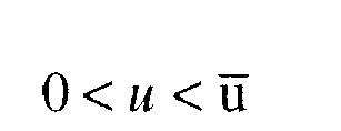

- Where xsurf is the
fuser roll 370 surface temperature and xcore isfuser roll 370 core temperature. The main idea of MPC is to choose the control action by repeatedly solving online an optimal control problem. This aims at minimizing a performance criterion S(k) over a future horizon P, subject to constraints on the manipulated inputs u and outputs xcore, where the future behavior is computed according to a model of the plant. Not only the magnitude of the input power can be constrained, but also the rate of input change can be added as a constraint. - At
step 4600, the dynamicpower management module 250 may determine whether the fuser warm-up time is reduced. If the dynamicpower management module 250 determines that the warm-up power is not reduced, the process goes to step 4700 where the dynamicpower management module 250 may adjust the selected power allocation. This step may also ensure that the core temperature does not reach an unacceptable level. The process then goes back tostep 4500. - Once the dynamic
power management module 250 determines that the warm-up power is reduced, the process goes to step 4800 and the dynamicpower management module 250 may apply the selected or adjusted power allocation. The process then goes to step 4900, and ends. -
FIGS. 5A-5B exemplary pie charts showing power allocation before and after the dynamic power management process is applied, respectively, in accordance with one possible embodiment of the disclosure. The total fuser element power is constant. The pie chart inFIG. 5B shows that more power is provided to thefuser roll 370 because that takes the longest to heat up. -
FIGS. 6A-6B illustrate exemplary graphs showing power allocation before and after the dynamic power management process is applied, respectively, in accordance with one possible embodiment of the disclosure.FIG. 6A is the temperature control with the current power allocation; whileFIG. 6B is the temperature profile after optimization. Notice the fuser roll core temperature doesn't violate its upper bound T̅core . - Embodiments as disclosed herein may also include computer-readable media for carrying or having computer-executable instructions or data structures stored thereon. Such computer-readable media can be any available media that can be accessed by a general purpose or special purpose computer. By way of example, and not limitation, such computer-readable media can comprise RAM, ROM, EEPROM, CD-ROM or other optical disk storage, magnetic disk storage or other magnetic storage devices, or any other medium which can be used to carry or store desired program code means in the form of computer-executable instructions or data structures. When information is transferred or provided over a network or another communications connection (either hardwired, wireless, or combination thereof) to a computer, the computer properly views the connection as a computer-readable medium. Thus, any such connection is properly termed a computer-readable medium. Combinations of the above should also be included within the scope of the computer-readable media.
- Computer-executable instructions include, for example, instructions and data which cause a general purpose computer, special purpose computer, or special purpose processing device to perform a certain function or group of functions. Computer-executable instructions also include program modules that are executed by computers in stand-alone or network environments. Generally, program modules include routines, programs, objects, components, and data structures, and the like that perform particular tasks or implement particular abstract data types. Computer-executable instructions, associated data structures, and program modules represent examples of the program code means for executing steps of the methods disclosed herein. The particular sequence of such executable instructions or associated data structures represents examples of corresponding acts for implementing the functions described therein.
- It will be appreciated that various of the above-disclosed and other features and functions, or alternatives thereof, may be desirably combined into many other different systems or applications. Also that various presently unforeseen or unanticipated alternatives, modifications, variations or improvements therein may be subsequently made by those skilled in the art which are also intended to be encompassed by the following claims.
Claims (13)
- A method for operating a fuser in a marking device, the fuser having a number of fuser elements associated therewith, comprising:determining a total power available for warm-up of fuser elements in a fuser;determining temperature constraints of the fuser elements;selecting a power allocation to be applied to the fuser elements;calculating a fuser warm-up time based on the determined total power available, the determined power constraints, and the selected power allocation; anddetermining whether the calculated fuser warm-up time is reduced, wherein if the calculated fuser warm-up time is reduced,applying the selected power allocation.
- The method of claim 1, wherein if the fuser warm-up time is not reduced,
adjusting the selected power allocation; and
applying the adjusted power allocation. - The method of claim 1 or claim 2, wherein the determined power constraints include warm-up times of all fuser elements.
- The method of any of the preceding claims, wherein the fuser elements include at least one of rolls and belts, preferably covered with a synthetic material.
- The method of any of the preceding claims, wherein the determined temperature constraints include fuser element overheat and power supply limit.
- The method of any of the preceding claims, wherein the calculating step is performed using model predictive control.
- A fusing apparatus in a marking device, comprising:a fuser that includes one or more heating elements; anda dynamic power management module that determines a total power available for warm-up of the fuser elements in the fuser, determines power constraints of the fuser elements, selects a power allocation to be applied to the fuser elements, calculates a fuser warm-up time based on the determined total power available, the determined power constraints, and the selected power allocation, determines whether the fuser warm-up time is reduced, wherein if the fuser warm-up time is reduced, the dynamic power management module applies the selected power allocation.
- The fusing apparatus of claim 7, wherein if the fuser warm-up time is not reduced, the dynamic power management module is adapted to adjust the selected power allocation and applies the adjusted power allocation.
- The fusing apparatus of claim 7 or claim 8, wherein the fuser elements include at least one of rolls and belts, preferably covered with a synthetic material.
- The fusing apparatus of any of claims 7 to 9, wherein the marking device is one of a copier, printer, and multi-function device.
- A fusing apparatus according to any of claims 7 to 10 adapted to carry out a method according to any of claims 1 to 6.
- A computer-readable medium storing instructions for controlling a computing device for operating a fuser in a marking device, the fuser having a number of fuser elements associated therewith, the instructions comprising:determining a total power available for warm-up of fuser elements in a fuser;determining power constraints of the fuser elements;selecting a power allocation to be applied to the fuser elements;calculating a fuser warm-up time based on the determined total power available, the determined power constraints, and the selected power allocation; anddetermining whether the fuser warm-up time is reduced, wherein if the fuser warm-up time is reduced,applying the selected power allocation.
- A computer readable medium according to claim 12, storing instructions for controlling a computing device for operating a fuser in a marking device according to a method according to any of claims 1 to 6.
Applications Claiming Priority (1)
| Application Number | Priority Date | Filing Date | Title |
|---|---|---|---|
| US12/023,563 US7764896B2 (en) | 2008-01-31 | 2008-01-31 | Method and apparatus for dynamic power management in marking devices |
Publications (2)
| Publication Number | Publication Date |
|---|---|
| EP2085831A2 true EP2085831A2 (en) | 2009-08-05 |
| EP2085831A3 EP2085831A3 (en) | 2010-08-11 |
Family
ID=40578122
Family Applications (1)
| Application Number | Title | Priority Date | Filing Date |
|---|---|---|---|
| EP09151672A Withdrawn EP2085831A3 (en) | 2008-01-31 | 2009-01-29 | Method and Apparatus for Dynamic Power Management in Marking Devices |
Country Status (3)
| Country | Link |
|---|---|
| US (1) | US7764896B2 (en) |
| EP (1) | EP2085831A3 (en) |
| JP (1) | JP2009181127A (en) |
Families Citing this family (2)
| Publication number | Priority date | Publication date | Assignee | Title |
|---|---|---|---|---|
| US20150205232A1 (en) * | 2014-01-22 | 2015-07-23 | Xerox Corporation | Systems and methods for providing and implementing low surface energy external heat rolls in image forming devices |
| JP6432284B2 (en) * | 2014-10-31 | 2018-12-05 | 株式会社リコー | Image forming apparatus and module activation method in image forming apparatus |
Citations (2)
| Publication number | Priority date | Publication date | Assignee | Title |
|---|---|---|---|---|
| JP2002182503A (en) * | 2000-12-14 | 2002-06-26 | Fuji Xerox Co Ltd | Fixing device |
| JP2006058684A (en) * | 2004-08-20 | 2006-03-02 | Fuji Xerox Co Ltd | Fixing device |
Family Cites Families (16)
| Publication number | Priority date | Publication date | Assignee | Title |
|---|---|---|---|---|
| DE69332233T2 (en) * | 1992-03-31 | 2003-04-17 | Canon K.K., Tokio/Tokyo | Image heater with control of the actuation of several heating elements |
| US5600406A (en) * | 1993-10-19 | 1997-02-04 | Mita Industrial Co., Ltd. | Fixing temperature control device |
| JP3167887B2 (en) * | 1995-06-28 | 2001-05-21 | シャープ株式会社 | Fixing device for image forming device |
| JP2000235319A (en) * | 1999-02-16 | 2000-08-29 | Sharp Corp | Developer fixing device and fixing method |
| JP2001236126A (en) * | 2000-02-25 | 2001-08-31 | Canon Inc | Heating body heating time prediction method of heating device and image forming apparatus |
| US6353718B1 (en) | 2000-11-17 | 2002-03-05 | Xerox Corporation | Xerographic fusing apparatus with multiple heating elements |
| JP4101572B2 (en) * | 2002-07-11 | 2008-06-18 | 東芝テック株式会社 | Image forming apparatus and image forming method |
| US6757503B2 (en) | 2002-10-30 | 2004-06-29 | Kabushiki Kaisha Toshiba | Fixing device in an image forming apparatus having multiple heater lamps |
| US6901226B2 (en) | 2003-05-19 | 2005-05-31 | Xerox Corporation | Power control for a xerographic fusing apparatus |
| JP2005249871A (en) * | 2004-03-01 | 2005-09-15 | Brother Ind Ltd | Image forming apparatus |
| JP2005266454A (en) * | 2004-03-19 | 2005-09-29 | Ricoh Co Ltd | Image forming apparatus |
| JP2006259365A (en) * | 2005-03-17 | 2006-09-28 | Fuji Xerox Co Ltd | Image forming apparatus |
| JP2006337497A (en) * | 2005-05-31 | 2006-12-14 | Canon Inc | Image forming apparatus |
| JP2007079142A (en) * | 2005-09-14 | 2007-03-29 | Ricoh Co Ltd | Heating device, fixing device and image forming apparatus |
| JP4931045B2 (en) * | 2006-06-06 | 2012-05-16 | 株式会社リコー | Power supply device and image forming apparatus |
| US7706708B2 (en) * | 2007-01-30 | 2010-04-27 | Kabushiki Kaisha Toshiba | Image forming apparatus which reduces the warm-up time of a fixing device, and control method thereof |
-
2008
- 2008-01-31 US US12/023,563 patent/US7764896B2/en not_active Expired - Fee Related
-
2009
- 2009-01-29 EP EP09151672A patent/EP2085831A3/en not_active Withdrawn
- 2009-01-30 JP JP2009019373A patent/JP2009181127A/en active Pending
Patent Citations (2)
| Publication number | Priority date | Publication date | Assignee | Title |
|---|---|---|---|---|
| JP2002182503A (en) * | 2000-12-14 | 2002-06-26 | Fuji Xerox Co Ltd | Fixing device |
| JP2006058684A (en) * | 2004-08-20 | 2006-03-02 | Fuji Xerox Co Ltd | Fixing device |
Also Published As
| Publication number | Publication date |
|---|---|
| EP2085831A3 (en) | 2010-08-11 |
| US20090196645A1 (en) | 2009-08-06 |
| JP2009181127A (en) | 2009-08-13 |
| US7764896B2 (en) | 2010-07-27 |
Similar Documents
| Publication | Publication Date | Title |
|---|---|---|
| CN101266447B (en) | Image forming apparatus and control method thereof | |
| JP5228896B2 (en) | Processing apparatus, image forming apparatus, processing program | |
| US8036559B2 (en) | Fixing unit and fixing temperature control method | |
| EP2267551B1 (en) | Image forming apparatus comprising a gloss difference reducing unit, image forming method and program | |
| JP5014371B2 (en) | A method and system for reducing the effects of temperature droop during fixing operations. | |
| JP7031241B2 (en) | Image forming device and program | |
| US10613477B2 (en) | Image forming apparatus and method of controlling fuser | |
| US7764896B2 (en) | Method and apparatus for dynamic power management in marking devices | |
| JP6492751B2 (en) | Image forming apparatus and image forming method | |
| US20170146937A1 (en) | Image forming apparatus and fuser driving control method | |
| JP2007003663A (en) | Heater controller | |
| JP6004929B2 (en) | Image heating control device | |
| JP6242123B2 (en) | Image forming apparatus and method of controlling image forming apparatus | |
| JP2016057545A (en) | Image forming apparatus, image forming system, curl prediction method, and program | |
| US9008533B2 (en) | Processing apparatus, image forming apparatus, processing method and computer readable information recording medium | |
| JP2019184778A (en) | Image forming apparatus and control method | |
| JP6173251B2 (en) | Image forming apparatus | |
| JP7224143B2 (en) | Image forming apparatus and charging bias control method | |
| JP4870637B2 (en) | Image forming apparatus | |
| JP6840479B2 (en) | Image heating device and image forming device | |
| JP6128144B2 (en) | Image forming apparatus | |
| JP2020118884A (en) | Image forming apparatus | |
| JPH09222823A (en) | Image forming device | |
| JP2018025645A (en) | Image forming apparatus | |
| JP2013097030A (en) | Image forming apparatus |
Legal Events
| Date | Code | Title | Description |
|---|---|---|---|
| PUAI | Public reference made under article 153(3) epc to a published international application that has entered the european phase |
Free format text: ORIGINAL CODE: 0009012 |
|
| AK | Designated contracting states |
Kind code of ref document: A2 Designated state(s): AT BE BG CH CY CZ DE DK EE ES FI FR GB GR HR HU IE IS IT LI LT LU LV MC MK MT NL NO PL PT RO SE SI SK TR |
|
| AX | Request for extension of the european patent |
Extension state: AL BA RS |
|
| PUAL | Search report despatched |
Free format text: ORIGINAL CODE: 0009013 |
|
| AK | Designated contracting states |
Kind code of ref document: A3 Designated state(s): AT BE BG CH CY CZ DE DK EE ES FI FR GB GR HR HU IE IS IT LI LT LU LV MC MK MT NL NO PL PT RO SE SI SK TR |
|
| AX | Request for extension of the european patent |
Extension state: AL BA RS |
|
| 17P | Request for examination filed |
Effective date: 20110211 |
|
| AKX | Designation fees paid |
Designated state(s): DE FR GB |
|
| 17Q | First examination report despatched |
Effective date: 20141030 |
|
| STAA | Information on the status of an ep patent application or granted ep patent |
Free format text: STATUS: THE APPLICATION IS DEEMED TO BE WITHDRAWN |
|
| 18D | Application deemed to be withdrawn |
Effective date: 20180801 |