EP2085653B1 - Continuous variable transmission device with low shift transmission pulley train - Google Patents
Continuous variable transmission device with low shift transmission pulley train Download PDFInfo
- Publication number
- EP2085653B1 EP2085653B1 EP09250264.0A EP09250264A EP2085653B1 EP 2085653 B1 EP2085653 B1 EP 2085653B1 EP 09250264 A EP09250264 A EP 09250264A EP 2085653 B1 EP2085653 B1 EP 2085653B1
- Authority
- EP
- European Patent Office
- Prior art keywords
- pulley
- transmission device
- transmission
- low shift
- train
- Prior art date
- Legal status (The legal status is an assumption and is not a legal conclusion. Google has not performed a legal analysis and makes no representation as to the accuracy of the status listed.)
- Not-in-force
Links
Images

Classifications
-
- F—MECHANICAL ENGINEERING; LIGHTING; HEATING; WEAPONS; BLASTING
- F16—ENGINEERING ELEMENTS AND UNITS; GENERAL MEASURES FOR PRODUCING AND MAINTAINING EFFECTIVE FUNCTIONING OF MACHINES OR INSTALLATIONS; THERMAL INSULATION IN GENERAL
- F16H—GEARING
- F16H37/00—Combinations of mechanical gearings, not provided for in groups F16H1/00 - F16H35/00
- F16H37/02—Combinations of mechanical gearings, not provided for in groups F16H1/00 - F16H35/00 comprising essentially only toothed or friction gearings
-
- F—MECHANICAL ENGINEERING; LIGHTING; HEATING; WEAPONS; BLASTING
- F16—ENGINEERING ELEMENTS AND UNITS; GENERAL MEASURES FOR PRODUCING AND MAINTAINING EFFECTIVE FUNCTIONING OF MACHINES OR INSTALLATIONS; THERMAL INSULATION IN GENERAL
- F16H—GEARING
- F16H9/00—Gearings for conveying rotary motion with variable gear ratio, or for reversing rotary motion, by endless flexible members
- F16H9/02—Gearings for conveying rotary motion with variable gear ratio, or for reversing rotary motion, by endless flexible members without members having orbital motion
- F16H9/04—Gearings for conveying rotary motion with variable gear ratio, or for reversing rotary motion, by endless flexible members without members having orbital motion using belts, V-belts, or ropes
- F16H9/12—Gearings for conveying rotary motion with variable gear ratio, or for reversing rotary motion, by endless flexible members without members having orbital motion using belts, V-belts, or ropes engaging a pulley built-up out of relatively axially-adjustable parts in which the belt engages the opposite flanges of the pulley directly without interposed belt-supporting members
- F16H9/16—Gearings for conveying rotary motion with variable gear ratio, or for reversing rotary motion, by endless flexible members without members having orbital motion using belts, V-belts, or ropes engaging a pulley built-up out of relatively axially-adjustable parts in which the belt engages the opposite flanges of the pulley directly without interposed belt-supporting members using two pulleys, both built-up out of adjustable conical parts
- F16H2009/166—Arrangements of two or more belt gearings mounted in series, e.g. for increasing ratio coverage
Definitions
- variable spacing transmission V-belt grooves of driving and driven pulleys is modulated, whereby the operative belt transmission radial distance of driving pulley or driven pulley is changed to further change the transmission speed ratio between the driving pulley and the driven pulley;
- the above said spacing modulation for variable spacing transmission V-belt grooves of driving or driven pulleys of the continuous variable transmission device is required to be driven by one or more than one kinds of axial driving forces including:
- the above said 1 ⁇ 5 methods are passive operations of continuous variable transmission function.
- Types of conventional continuous variable transmission devices of different input and output shafts structures are numerous including: rubber belt type, metal belt type, chain type, or electronic (ECVT) type, friction disk type or known continuous variable transmission device of different shafts type, etc.
- ECVT electronic
- US 3926020 discloses an automatic transmission for vehicles in which the speed ratio of the transmission is automatically adjusted in response to a control signal which is generated as a function of the speed of the drive system of the vehicle.
- the continuous variable transmission device with low shift transmission pulley train is passively operated by an axial driving force generated by operating torque by axially pre-pressed springs on the driven pulleys, thereby to modulate and operate the speed ratio of the continuous variable transmission thereof.
- continuous variable transmission devices of different shafts type is advantageous in convenient operation for its automatic speed ratio adjustment function according to the rotational speed change of the driving pulley input shaft and the size of loading torque at loading side
- said continuous variable transmission device of different shafts type has the imperfections:
- the invented continuous variable transmission device with low shift transmission pulley train is innovatingly disclosed by the features of claim 1.
- the continuous variable transmission device with low shift transmission pulley train is passively operated by an axial driving force generated by operating torque to execute axial drive to the driven pulley and further provided with axially pre-pressed springs to constitute the continuous variable transmission function; and further referring to input preset operating modes, detected speeds and torques, etc. thereby to modulate and operate the speed ratio of the continuous variable transmission thereof.
- the continuous variable transmission device of different shafts type is advantageous in convenient operation for its automatic speed ratio adjustment function according to the rotational speed change of the driving pulley input shaft and the size of the loading torque at loading side, said continuous variable transmission device of different shafts type has the imperfections:
- the invented continuous variable transmission device with low shift transmission pulley train is innovatingly disclosed by the features of claim 1.
- the continuous variable transmission device with low shift transmission pulley train is constituted by the following:
- the low shift transmission pulley train 102 is constituted by the following:
- the continuous variable transmission device with low shift transmission pulley train constituted by above said main structures includes that an input shaft 101 of the continuous variable transmission device of different shafts type 100 is additionally installed with a driving pulley of low shift transmission pulley train 102, and an unidirectional transmission device 111 is further installed between the two.
- Transmission direction of said unidirectional transmission device 111 shall allow said continuous variable transmission device of low shift transmission pulley train 102 to provide that: during higher load operation, if a decelerating type continuous variable transmission device is adopted by the continuous variable transmission device of differnet shafts type 100 to operate in a maximum deceleration speed ratio or a near maximum deceleration speed ratio status, or if an accelerating type continuous variable transmission device is adopted to operate in a minimum acceleration speed ratio or a near minimum deceleration speed ratio status, thereby to make the rotational speed of the driving pulley of low shift transmission pulley train 102 lower than that of the input shaft 101 in the same revolving direction, then the revolving kinetic energy of the input shaft 101 is transmitted through the unidirectional tansmission device 111 and the low shift transmission pulley train 102 to drive the output shaft 103 and further to drive the load.
- the power originally transmitted directly through said continuous variable transmission device of different shafts type 100 is changed to be transmitted through said low shift transmission pulley train 102 to further drive the output shaft 103.
- the power is directly transmitted through said continuous variable transmission device of different shafts type 100 to drive the output shaft 103;
- an unidirectional transmission device 111 is selected to be installed between the driven pulley of low shift transmission pulley train 102 and the output shaft 103, then during higher load operation, if a decelerating type continuous variable transmission device is adopted by the continuous variable transmission device of differnet shafts type 100 to operate in a maximum deceleration speed ratio or a near maximum deceleration speed ratio status, or if an accelerating type continuous variable transmission device is adopted to operate in a minimum acceleration speed ratio or a near minimum deceleration speed ratio status, thereby to make rotational speed of the driven pulley of low shift transmission pulley train 102 higher than that of the output shaft 103 in the same revolving direction, then the revolving kinetic energy is transmitted through the low shift transmission pulley train 102 and the unidirectional tansmission device 111 to drive the output shaft 103 and further to drive the load.
- the power originally transmitted directly through said continuous variable transmission device of different shafts type 100 is changed to be transmitted through said low shift transmission pulley train 102 to further drive the output shaft 103.
- the power is directly transmitted through said continuous variable transmission device of different shafts type 100 to drive the output shaft 103.
- a middle transmission pulley for accelerating speed ratio or decelerating speed ratio can be installed to satisfy the needs for accelerating speed ratio or decelerating speed ratio in order to ensure a better transmission efficiency, wherein said middle transmission pulley includes:
- the low shift transmission pulley train of said continuous variable transmission device with low shift transmission pulley train can be selected according to application requirements to include the following:
- input methods for supplying revolving kinetic energy to the input shaft 101 can be selected based on application requirements to include the following:
- the revolving kinetic energy output from the output shaft 103 of said continuous variable transmission of low shift transmission pulley train can be selected according to application requirements to include the following:
- the practical applied structures of said continuous variable transmission device of different shafts type 100 and said low shift transmission pulley train 102 can be selectively made to independently separated mechanical devices and combined afterwards for transmission or made to an integral structure or made to a structure of a common integrated mechanical device and a common integrated casing.
- said continuous variable transmission device with low shift transmission pulley train is characterized in that during high load operation, the kinetic energy is transmitted through said low shift transmission pulley train 102 to drive the output shaft 103 and to further drive the load, thereby to extend the service life of said continuous transmission device and to promote its loading efficiency.
- a continuous variable transmission device with low shift transmission pulley train is innovatingly disclosed by that a low shift transmission pulley train with fixed speed ratio and attached unidirectional transmission device in the same revolving direction are installed between the input shaft and output shaft of a continuous variable transmission device, wherein if a decelerating type continuous variable transmission device is used to operated at maximum decelerating speed ratio or near maximum decelerating speed ratio status, or an accelerating type continuous variable transmission device is used to operate at minimum accelerating speed ratio or near minimum accelerating speed ratio status, then during high load operation, when the driving pulley rotational speed of low shift transmission pulley train is lower than that of the input shaft in the same revolving direction, the revolving kinetic energy of the input shaft is transmitted through the unidirectional transmission device and the low shift transmission pulley train to drive the output shaft and further to drive the load; at said status, the power originally transmitted through the continuous variable transmission device of different shafts type is changed to be transmitted through the low shift transmission pulley train.
- a continuous variable transmission device of different input and output shafts structure comprises at least one kind of rubber belt type, metal belt type, chain type, or electronic (ECVT) type, friction disk type continuous variable transmission devices, wherein transmission speed ratio thereof can be either passively automatically modulated by following torque or following rotational speed; or actively modulated by applying a linear driving force either generated by an externally powered linear driving device or by a revolving driving device via mechanical transmission for conversion to change spacing between the transmission V-belt grooves of both or either of driving and driven pulleys.
- ECVT electronic
- an input shaft (101) is arranged to receive a revolving kinetic energy input, whereby said revolving kinetic energy is transmitted to the driving pulley of the continuous variable transmission device of different shafts type (100) and to the input end of the unidirectional transmission device (111).
- an output shaft (103) is arranged to provide revolving kinetic energy output for driving the load, whereby the revolving kinetic energy from driven pulley of the continuous variable transmission device of different shafts type (100) or from the driven pulley of low shift transmission pulley train (102) is transmitted by it to the load.
- a unidirectional transmission device (111) is constituted by an unidirectional transmission device in radial direction type or an unidirectional transmission device in axial direction type, including the constitution by an unidirectional bearing with unidirectional transmission function, an unidirectional clutch or an unidirectional transmission mechanism or device, wherein said unidirectional transmission device (111) can be optionally installed as needed between the input shaft (101) and the driving pulley of low shift transmission pulley train (102), or installed as needed between the driven pulley of the low shift transmission pulley train (102) and the output shaft (103).
- the transmission direction of the unidirectional transmission device (111) is that when rotational speed of the input shaft (101) is higher than that of the driving pulley of the low shift transmission pulley train (102) in the same revolving direction, the revolving kinetic energy is transmitted to the driving pulley of the low shift transmission pulley train (102); on the contrary, if it is not so, the revolving kinetic energy from the input shaft (101) is not transmitted to the driving pulley of low shift transmission pulley train (102).
- the low shift transmission pulley train (102) comprises a driving pulley which is driven by the input shaft (101) and a driven pulley for driving the output shaft (103), wherein said driving pulley and driven pulley are transmitted in the same revolving direction, the transmission speed ratio thereof appears a low shift transmission in decelerating transmission relative to the continuous variable transmission device of different shafts type (100), and the speed ratio relationship between the low shift transmission pulley train (102) and the continuous variable transmission device of different shafts type (100) is:
- the low shift transmission pulley train (102) is constituted by the following:
- the input methods for supplying revolving kinetic energy to the input shaft (101) may be selected based on application requirements to include one or more than one following inputting methods:
- the revolving kinetic energy output from the output shaft (103) may be selected according to application requirements to include one or more than one outputting methods as following:
- the practical applied structures of said continuous variable transmission device of different shafts type (100) and said low shift transmission pulley train (102) can be selectively made to independently separated mechanical devices and combined afterwards for transmission or made to an integral structure or made to a structure of a common integrated mechanical device and a common integrated casing.
Landscapes
- Engineering & Computer Science (AREA)
- General Engineering & Computer Science (AREA)
- Mechanical Engineering (AREA)
- Transmission Devices (AREA)
- Transmissions By Endless Flexible Members (AREA)
- Arrangement And Driving Of Transmission Devices (AREA)
Description
- The operation schemes of continuous transmission for various known continuous variable transmission devices of different shafts type include:
- The spacing between the variable spacing transmission V-belt grooves of driving and driven pulleys is modulated, whereby the operative belt transmission radial distance of driving pulley or driven pulley is changed to further change the transmission speed ratio between the driving pulley and the driven pulley;
- The above said spacing modulation for variable spacing transmission V-belt grooves of driving or driven pulleys of the continuous variable transmission device is required to be driven by one or more than one kinds of axial driving forces including:
- 1. Through a variable centrifugal force generation mechanism by changes of the rotational speed of the input shaft to generate a variable axial driving force whereby to change the spacing of the transmission V-belt grooves of the driving pulley;
- 2. Through a variable centrifugal force generating mechanism by changes of the rotational speed of the output shaft to generate a variable axial driving force whereby to change the spacing of the transmission V-belt grooves of the driven pulley;
- 3. Through a variable axial driving force generating mechanism by changes of the output shaft torque to generate a variable axial driving force whereby to change the spacing of the transmission V-belt grooves of the driving pulley;
- 4. Through a variable axial driving force generating mechanism by changes of the output shaft torque to generate a variable axial driving force whereby to change the spacing of the transmission V-belt grooves of the driven pulley;
- 5. The driving or driven pulley is provided an axial pre-pressed spring, whereby the driving or driven pulley is pulled by the belt type transmission component to generate an axial driving force, whereby to change the variable spacing of the transmission V-belt grooves of both or either of the driving or driving pulley;
- The above said 1~5 methods are passive operations of continuous variable transmission function.
- 6. A linear driving force actively generated manually, or by mechanical power, electromagnetic effect, hydraulically or pneumatically driven linear driving device; or a revolving kinetic energy generated by driving the electric motor, hydraulic motor or pneumatic motor is converted through a mechanical transmission device to an axial linear type driving force whereby to further change the spacing of variable spacing transmission V-belt grooves of both or either of the driving pulley or driven pulley. Said method is the active operation of continuous variable transmission.
- Types of conventional continuous variable transmission devices of different input and output shafts structures are numerous including: rubber belt type, metal belt type, chain type, or electronic (ECVT) type, friction disk type or known continuous variable transmission device of different shafts type, etc.
-
US 3926020 discloses an automatic transmission for vehicles in which the speed ratio of the transmission is automatically adjusted in response to a control signal which is generated as a function of the speed of the drive system of the vehicle. - This document can be seen to disclose
a continuously-variable transmission device, having an input shaft and an output shaft, the device comprising: - a low shift transmission pulley train, which has a a driving pulley and a driven pulley, and
- a unidirectional transmission device, arranged to rotate in the same direction as one of the pulleys of the pulley train;
- The continuous variable transmission device with low shift transmission pulley train is passively operated by an axial driving force generated by operating torque by axially pre-pressed springs on the driven pulleys, thereby to modulate and operate the speed ratio of the continuous variable transmission thereof.
- Although the continuous variable transmission devices of different shafts type is advantageous in convenient operation for its automatic speed ratio adjustment function according to the rotational speed change of the driving pulley input shaft and the size of loading torque at loading side, said continuous variable transmission device of different shafts type has the imperfections:
- 1. Due to low transmittable power, it is only suitable for middle to small power applications;
- 2. Transmission efficiency of the continuous variable transmission device of different shafts type is too low;
- 3. Durability enhancement is required.
- The invented continuous variable transmission device with low shift transmission pulley train is innovatingly disclosed by the features of claim 1.
-
-
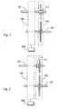
Fig. 1 is a structural schematic view showing that the invention is installed with a radial direction type unidirectional transmission device. -
Fig. 2 is a structural schematic view showing that the invention is installed with an axial direction type unidirectional transmission device. -
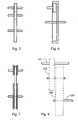
Fig. 3 is a structural schematic view of the invention showing that an unidirectional transmission device is installed between the driven pulley of the low shift transmission pulley train and the output shaft. -
Fig. 4 is a structural schematic view showing that the low shift transmission pulley train of the invention is constituted by a driving chain pulley, a driven chain pulley and a transmission chain. -
Fig. 5 is a structural schematic view showing that the low shift transmission pulley train is constituted by a driving pulley, a middle driven pulley and a driven pulley. -
Fig. 6 is a structural schematic view showing that the low shift transmission pulley train is constituted by a smaller outer diameter transmission pulley and a larger outer diameter inner transmission pulley. -
Fig. 7 is a structural schematic view showing that the low shift transmission pulley train is constituted by a driving belt pulley, a driven belt pulley and a transmission belt. -
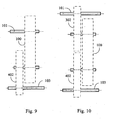
Fig. 8 is a structural schematic view of the invention showing that a speed change pulley train is installed between the input shaft and the driving pulley of the continuous variable transmission device of different shafts type. -
Fig. 9 is a structural schematic view of the invention showing that a speed change pulley train is installed between the output shaft and the driven pulley of the continuous variable transmission device of different shafts type. -
Fig. 10 is a structural schematic view of the invention showing that speed change pulley trains are installed between the input shaft and the driving pulley of the continuous variable transmission device of different shafts type and between the output shaft and the driven pulley of the continuous variable transmission device of different shafts type. -
- 100:
- Continuous variable transmission device of different shafts type
- 101:
- Input shaft
- 102:
- Low shift transmission pulley train
- 103:
- Output Shaft
- 111:
- Unidirectional transmission device
- 302, 402:
- Speed change pulley train
- 800:
- Driving control device
- The continuous variable transmission device with low shift transmission pulley train is passively operated by an axial driving force generated by operating torque to execute axial drive to the driven pulley and further provided with axially pre-pressed springs to constitute the continuous variable transmission function; and further referring to input preset operating modes, detected speeds and torques, etc. thereby to modulate and operate the speed ratio of the continuous variable transmission thereof.
- Although the continuous variable transmission device of different shafts type is advantageous in convenient operation for its automatic speed ratio adjustment function according to the rotational speed change of the driving pulley input shaft and the size of the loading torque at loading side, said continuous variable transmission device of different shafts type has the imperfections:
- 1. Due to low transmittable power, it is only suitable for middle to small power applications;
- 2. Transmission efficiency of the continuous variable transmission device of different shafts type is too low;
- 3. Durability enhancement is required.
- The invented continuous variable transmission device with low shift transmission pulley train is innovatingly disclosed by the features of claim 1.
- The continuous variable transmission device with low shift transmission pulley train is constituted by the following:
- As shown in
Fig. 1 , besides the relevant mechanisms in the conventional continuous variable transmission devices, the continuous variable transmission device with low shift transmission pulley train is further mainly constituted by:- A continuous variable transmission device of different shafts type 100: It is a continuous variable transmission device of different input and output shafts structure comprises at least one kind of rubber belt type, metal belt type, chain type, or electronic (ECVT) type, friction disk type continuous variable transmission devices, wherein transmission speed ratio thereof is passively automatically modulated by following torque.
- An input shaft 101: It is the rotating shaft to receive a revolving kinetic energy input, whereby said revolving kinetic energy is transmitted to the driving pulley of the continuous variable transmission device of different shafts type 100 and to the input end of the
unidirectional transmission device 111; - An output shaft 103: it is a rotating shaft to provide revolving kinetic energy output for driving the load, whereby the revolving kinetic energy from driven pulley of the continuous variable transmission device of different shafts type 100 or from the driven pulley of low shift
transmission pulley train 102 is transmitted by it to the load; - An unidirectional transmission device 111: It is constituted by an unidirectional transmission device in radial direction type as applied in
Fig. 1 or an unidirectional transmission device in axial direction type as applied inFig. 2 , including the constitution by an unidirectional bearing with unidirectional transmission function, an unidirectional clutch or an unidirectional transmission mechanism or device, wherein saidunidirectional transmission device 111 can be optionally installed as needed between theinput shaft 101 and the driving pulley of low shifttransmission pulley train 102, or installed as needed between the driven pulley of the low shifttransmission pulley train 102 and theoutput shaft 103 as shown inFig. 3 ;
The transmission direction of theunidirectional transmission device 111 is that when rotational speed of theinput shaft 101 is higher than that of the driving pulley of the low shifttransmission pulley train 102 in the same revolving direction, the revolving kinetic energy is transmitted to the driving pulley of the low shifttransmission pulley train 102; on the contrary, if it is not so, the revolving kinetic energy from theinput shaft 101 is not transmitted to the driving pulley of low shifttransmission pulley train 102; - The low shift transmission pulley train 102: It comprises a driving pulley which is driven by the
input shaft 101 and a driven pulley for driving theoutput shaft 103, wherein said driving pulley and driven pulley are transmitted in the same revolving direction, the transmission speed ratio thereof appears a low shift transmission in decelerating transmission relative to the continuous variable transmission device of different shafts type 100, and the speed ratio relationship between the low shifttransmission pulley train 102 and the continuous variable transmission device of different shafts type 100 is:- 1. Speed ratio of the driving pulley to drive the driven pulley of low shift
transmission pulley train 102 ≤ speed ratio of the continuous variable transmission device of different shafts type 100 in low speed output; - 2. Speed ratio of the continuous variable transmission device of different shafts type 100 in low speed output < Speed ratio of the driving pulley to drive the driven pulley of low shift
transmission pulley train 102 < speed ratio of the continuous variable transmission device of different shafts type 100 in high speed output;
- 1. Speed ratio of the driving pulley to drive the driven pulley of low shift
- The low shift
transmission pulley train 102 is constituted by the following: - 1. It is constituted by a driving chain pulley, a driven chain pulley, and an attached transmission chain, wherein
Fig. 4 is a structural schematic view showing that the low shifttransmission pulley train 102 of the invention is constituted by a driving chain pulley, a driven chain pulley and an attached transmission chain; or - 2. It is constituted by a driving pulley, a middle driven pulley and a driven pulley, wherein said driving pulley, middle driven pulley and driven pulley include constitutions by gears or friction pulleys.
Fig. 5 is a structural schematic view showing that the low shifttransmission pulley train 102 is constituted by a driving pulley, a middle driven pulley and a pulley; or - 3. It is constituted by an inner gear train or an inner friction pulley train comprising a smaller outer diameter transmission pulley and a larger outer diameter inner transmission pulley.
Fig. 6 is a structural schematic view showing that the low shifttransmission pulley train 102 is constituted by a smaller outer diameter transmission pulley and a larger outer diameter inner transmission pulley; or - 4. It is constituted by a driving belt pulley, a driven belt pulley and an attached transmission belt such as a canvas belt, a steel belt, or a chain belt.
Fig. 7 is a structural schematic view showing that the low shifttransmission pulley train 102 is constituted by a driving belt pulley, a driven belt pulley and a transmission belt. - The continuous variable transmission device with low shift transmission pulley train constituted by above said main structures includes that an
input shaft 101 of the continuous variable transmission device of different shafts type 100 is additionally installed with a driving pulley of low shifttransmission pulley train 102, and anunidirectional transmission device 111 is further installed between the two. Transmission direction of saidunidirectional transmission device 111 shall allow said continuous variable transmission device of low shifttransmission pulley train 102 to provide that: during higher load operation, if a decelerating type continuous variable transmission device is adopted by the continuous variable transmission device of differnet shafts type 100 to operate in a maximum deceleration speed ratio or a near maximum deceleration speed ratio status, or if an accelerating type continuous variable transmission device is adopted to operate in a minimum acceleration speed ratio or a near minimum deceleration speed ratio status, thereby to make the rotational speed of the driving pulley of low shifttransmission pulley train 102 lower than that of theinput shaft 101 in the same revolving direction, then the revolving kinetic energy of theinput shaft 101 is transmitted through theunidirectional tansmission device 111 and the low shifttransmission pulley train 102 to drive theoutput shaft 103 and further to drive the load. At said status, the power originally transmitted directly through said continuous variable transmission device of different shafts type 100 is changed to be transmitted through said low shifttransmission pulley train 102 to further drive theoutput shaft 103. During lower load operation, the power is directly transmitted through said continuous variable transmission device of different shafts type 100 to drive theoutput shaft 103; - If an
unidirectional transmission device 111 is selected to be installed between the driven pulley of low shifttransmission pulley train 102 and theoutput shaft 103, then during higher load operation, if a decelerating type continuous variable transmission device is adopted by the continuous variable transmission device of differnet shafts type 100 to operate in a maximum deceleration speed ratio or a near maximum deceleration speed ratio status, or if an accelerating type continuous variable transmission device is adopted to operate in a minimum acceleration speed ratio or a near minimum deceleration speed ratio status, thereby to make rotational speed of the driven pulley of low shifttransmission pulley train 102 higher than that of theoutput shaft 103 in the same revolving direction, then the revolving kinetic energy is transmitted through the low shifttransmission pulley train 102 and theunidirectional tansmission device 111 to drive theoutput shaft 103 and further to drive the load. At said status, the power originally transmitted directly through said continuous variable transmission device of different shafts type 100 is changed to be transmitted through said low shifttransmission pulley train 102 to further drive theoutput shaft 103. During lower load operation, the power is directly transmitted through said continuous variable transmission device of different shafts type 100 to drive theoutput shaft 103. - For sake of efficiency, when diameters of the driving pulley and the driven pulley in the continuous variable transmission device of differnet shafts type 100 of said continuous variable transmission device with low shift transmission pulley train are made more similar to each other to ensure a better efficiency, a middle transmission pulley for accelerating speed ratio or decelerating speed ratio can be installed to satisfy the needs for accelerating speed ratio or decelerating speed ratio in order to ensure a better transmission efficiency, wherein said middle transmission pulley includes:
- 1. A speed
change pulley train 302 is further installed between theinput shaft 101 and the driving pulley of continuous variable transmission device of different shafts type 100 to change the total speed ratio of theinput shaft 101 and theoutput shaft 103 and is matched to required revolving direction.Fig. 8 is a structural schematic view of the invention showing that a speed change pulley train is installed between theinput shaft 101 and the driving pulley of continuous variable transmission device of different shafts type 100; or - 2. A speed
change pulley train 402 is further installed between theoutput shaft 103 and the driven pulley of continuous variable transmission device of different shafts type 100 to change the total speed ratio of theinput shaft 101 and theoutput shaft 103 and is matched to required revolving direction.Fig. 9 is a structural schematic view of the invention showing that a speed change pulley train is installed between theoutput shaft 103 and the driven pulley of continuous variable transmission device of different shafts type 100; or - 3. The speed change pulley trains 302, 402 are simultaneously installed between the
input shaft 101 and the driving pulley of continuous variable transmission device of different shafts type 100 and between theoutput shaft 103 and the driven pulley of continuous variable transmission device of different shafts type 100 to change the total speed ratio of theinput shaft 101 through the continuous variable transmission device of different shafts type 100 to theoutput shaft 103 and are matched to required revolving direction.Fig. 10 is a structural schematic view of the invention showing that speed change pulley trains are installed between theinput shaft 101 and the driving pulley of continuous variable transmission device of different shafts type 100 and between theoutput shaft 103 and the driven pulley of continuous variable transmission device of different shafts type 100; - The low shift transmission pulley train of said continuous variable transmission device with low shift transmission pulley train can be selected according to application requirements to include the following:
- 1. To be constituted by a single stage low shift transmission pulley train of fixed speed ratio;
- 2. To be constituted by a multi-stage type low shift variable transmission pulley train of manual shift or automatic transmission.
- For said continuous variable transmission device with low shift transmission pulley train, input methods for supplying revolving kinetic energy to the
input shaft 101 can be selected based on application requirements to include the following: - 1. The
input shaft 101 is for receiving direct revolving power source input from revolving power source such as engine, motor or generator or input from flywheel, wind power fan blades, gas or liquid turbines, or manual power, etc. ; - 2. The revolving power sources as said in item 1 supplied to the
input shaft 101 for output is first controlled by a clutching device before providing revolving kinetic energy output; - 3. The revolving power sources as said in item 1 supplied to the
input shaft 101 for output is further through a speed change device with fixed speed ratio, or a stepped or stepless speed change device of manual shift or automatic transmission, or a fluid transmission device, or an electromagnetic eddy current transmission device to provide revolving kinetic energy output; - 4. The revolving power sources as said in item 1 supplied to the
input shaft 101 for output is further through a clutching device and a speed change device with fixed speed ratio, or a stepped or stepless speed change device of manual shift or automatic transmission, or a fluid transmission device, or an electromagnetic eddy current transmission device to provide revolving kinetic energy output. - The revolving kinetic energy output from the
output shaft 103 of said continuous variable transmission of low shift transmission pulley train can be selected according to application requirements to include the following: - 1. The revolving kinetic energy output from the
output shaft 103 is directly used to drive the load; - 2. The revolving kinetic energy output from the
output shaft 103 is through a clutching device to further drive the load; - 3. The revolving kinetic energy from the
output shaft 103 is through a speed change device with fixed speed ratio, or a stepless or stepped speed change device of manual shift or automatic transmission, or a fluid transmission device, or electromagnetic eddy current transmission device to further drive the load; - 4. The revolving kinetic energy output from the
output shaft 103 is through a clutching device and a speed change device with fixed speed ratio, or a stepless or stepped speed change device of manual shift or automatic transmission, or a fluid transmission device, or an electromagnetic eddy current transmission device to further drive the load. - The practical applied structures of said continuous variable transmission device of different shafts type 100 and said low shift
transmission pulley train 102 can be selectively made to independently separated mechanical devices and combined afterwards for transmission or made to an integral structure or made to a structure of a common integrated mechanical device and a common integrated casing. - As summarized from above descriptions, said continuous variable transmission device with low shift transmission pulley train is characterized in that during high load operation, the kinetic energy is transmitted through said low shift
transmission pulley train 102 to drive theoutput shaft 103 and to further drive the load, thereby to extend the service life of said continuous transmission device and to promote its loading efficiency. - A continuous variable transmission device with low shift transmission pulley train is innovatingly disclosed by that a low shift transmission pulley train with fixed speed ratio and attached unidirectional transmission device in the same revolving direction are installed between the input shaft and output shaft of a continuous variable transmission device, wherein if a decelerating type continuous variable transmission device is used to operated at maximum decelerating speed ratio or near maximum decelerating speed ratio status, or an accelerating type continuous variable transmission device is used to operate at minimum accelerating speed ratio or near minimum accelerating speed ratio status, then during high load operation, when the driving pulley rotational speed of low shift transmission pulley train is lower than that of the input shaft in the same revolving direction, the revolving kinetic energy of the input shaft is transmitted through the unidirectional transmission device and the low shift transmission pulley train to drive the output shaft and further to drive the load; at said status, the power originally transmitted through the continuous variable transmission device of different shafts type is changed to be transmitted through the low shift transmission pulley train.
- In a preferred embodiment, a continuous variable transmission device of different input and output shafts structure comprises at least one kind of rubber belt type, metal belt type, chain type, or electronic (ECVT) type, friction disk type continuous variable transmission devices, wherein transmission speed ratio thereof can be either passively automatically modulated by following torque or following rotational speed; or actively modulated by applying a linear driving force either generated by an externally powered linear driving device or by a revolving driving device via mechanical transmission for conversion to change spacing between the transmission V-belt grooves of both or either of driving and driven pulleys.
- Preferably, an input shaft (101) is arranged to receive a revolving kinetic energy input, whereby said revolving kinetic energy is transmitted to the driving pulley of the continuous variable transmission device of different shafts type (100) and to the input end of the unidirectional transmission device (111).
- Advantageously, an output shaft (103) is arranged to provide revolving kinetic energy output for driving the load, whereby the revolving kinetic energy from driven pulley of the continuous variable transmission device of different shafts type (100) or from the driven pulley of low shift transmission pulley train (102) is transmitted by it to the load.
- Preferably, a unidirectional transmission device (111) is constituted by an unidirectional transmission device in radial direction type or an unidirectional transmission device in axial direction type, including the constitution by an unidirectional bearing with unidirectional transmission function, an unidirectional clutch or an unidirectional transmission mechanism or device, wherein said unidirectional transmission device (111) can be optionally installed as needed between the input shaft (101) and the driving pulley of low shift transmission pulley train (102), or installed as needed between the driven pulley of the low shift transmission pulley train (102) and the output shaft (103).
- Advantageously, the transmission direction of the unidirectional transmission device (111) is that when rotational speed of the input shaft (101) is higher than that of the driving pulley of the low shift transmission pulley train (102) in the same revolving direction, the revolving kinetic energy is transmitted to the driving pulley of the low shift transmission pulley train (102); on the contrary, if it is not so, the revolving kinetic energy from the input shaft (101) is not transmitted to the driving pulley of low shift transmission pulley train (102).
- Preferably, the low shift transmission pulley train (102) comprises a driving pulley which is driven by the input shaft (101) and a driven pulley for driving the output shaft (103), wherein said driving pulley and driven pulley are transmitted in the same revolving direction, the transmission speed ratio thereof appears a low shift transmission in decelerating transmission relative to the continuous variable transmission device of different shafts type (100), and the speed ratio relationship between the low shift transmission pulley train (102) and the continuous variable transmission device of different shafts type (100) is:
- 1) Speed ratio of the driving pulley to drive the driven pulley of low shift transmission pulley train (102) ≤ speed ratio of the continuous variable transmission device of different shafts type (100) in low speed output;
- 2) Speed ratio of the continuous variable transmission device of different shafts type (100) in low speed output < Speed ratio of the driving pulley to drive the driven pulley of low shift transmission pulley train (102) < speed ratio of the continuous variable transmission device of different shafts type (100) in high speed output.
- Advantageously, the low shift transmission pulley train (102) is constituted by the following:
- -- It is constituted by a driving chain pulley, a driven chain pulley, and an attached transmission chain;
- -- It is constituted by a driving pulley, a middle driven pulley and a driven pulley, wherein said driving pulley, middle driven pulley and driven pulley include constitutions by gears or friction pulleys;
- -- It is constituted by an inner gear train or an inner friction pulley train comprising a smaller outer diameter transmission pulley and a larger outer diameter inner transmission pulley;
- -- It is constituted by a driving belt pulley, a driven belt pulley and an attached transmission belt such as a canvas belt, a steel belt, or a chain belt.
- The input methods for supplying revolving kinetic energy to the input shaft (101) may be selected based on application requirements to include one or more than one following inputting methods:
- 1) The input shaft (101) is for receiving direct revolving power source input from revolving power source such as engine, motor or generator or input from flywheel, wind power fan blades, gas or liquid turbines, or manual power;
- 2) The revolving power sources as said in item 1) supplied to the input shaft (101) for output is first controlled by a clutching device before providing revolving kinetic energy output;
- 3) The revolving power sources as said in item 1) supplied to the input shaft (101) for output is further through a speed change device with fixed speed ratio, or a stepped or stepless speed change device of manual shift or automatic transmission, or a fluid transmission device, or an electromagnetic eddy current transmission device to provide revolving kinetic energy output;
- 4) The revolving power sources as said in item 1) supplied to the input shaft (101) for output is further through a clutching device and a speed change device with fixed speed ratio, or a stepped or stepless speed change device of manual shift or automatic transmission, or a fluid transmission device, or an electromagnetic eddy current transmission device to provide revolving kinetic energy output.
- The revolving kinetic energy output from the output shaft (103) may be selected according to application requirements to include one or more than one outputting methods as following:
- 1) The revolving kinetic energy output from the output shaft (103) is directly used to drive the load;
- 2) The revolving kinetic energy output from the output shaft (103) is through a clutching device to further drive the load;
- 3) The revolving kinetic energy from the output shaft (103) is through a speed change device with fixed speed ratio, or a stepless or stepped speed change device of manual shift or automatic transmission, or a fluid transmission device, or electromagnetic eddy current transmission device to further drive the load;
- 4) The revolving kinetic energy output from the output shaft (103) is through a clutching device and a speed change device with fixed speed ratio, or a stepless or stepped speed change device of manual shift or automatic transmission, or a fluid transmission device, or an electromagnetic eddy current transmission device to further drive the load.
- The practical applied structures of said continuous variable transmission device of different shafts type (100) and said low shift transmission pulley train (102) can be selectively made to independently separated mechanical devices and combined afterwards for transmission or made to an integral structure or made to a structure of a common integrated mechanical device and a common integrated casing.
wherein, during high load operation, the revolving kinetic energy of the input shaft is transmitted through the unidirectional transmission device and the low shift transmission pulley train to drive the output shaft and further to drive a Ioad.
Claims (12)
- A transmission device, having an input shaft (101) and an output shaft (103), the device comprising:a continuously-variable transmission device (100);a low shift fixed-speed ratio transmission pulley train (102) having a driving pulley and a driven pulley; anda unidirectional transmission device (111), arranged to rotate in the same direction as one of the pulleys of the pulley train (102);wherein the low shift fixed-speed ratio transmission pulley train (102) and the unidirectional transmission device (111) are installed between the input shaft (101) and output shaft (103); andwherein the continuously variable transmission device is installed between the input shaft (101) and the output shaft (103) so as to transmit power directly from the input shaft (101) to the output shaft (103) and is provided with axially pre-pressed springs at a driven pulley to constitute the continuous variable transmission function;wherein, the transmission speed ratio of the continuously variable transmission device (100) is passively automatically modulated by following torque, such that when driving the output shaft by means of the continuously variable transmission device (100) and the load becoming a high load operation, and when the speed of rotation of the driving pulley of the low shift fixed-speed ratio transmission pulley train (102) is lower than that of the input shaft (101), the revolving kinetic energy of the input shaft (101) is transmitted through the unidirectional transmission device (111) and the low shift fixed-speed ratio transmission pulley train (102) to drive the output shaft (103) and further to drive a load.
- A transmission device according to claim 1, further comprising at least one friction disk, wherein the friction disk is one or more of the following types: rubber belt type, metal belt type, chain type, and electronic (ECVT) type.
- A transmission device according to any one of the preceding claims, wherein the input shaft is arranged to receive a kinetic energy input, whereby said kinetic energy is transmitted to a driving pulley of the continuously-variable transmission device (100) and to an input end of the unidirectional transmission device (111).
- A transmission device according to any one of the preceding claims, wherein the output shaft is arranged to provide kinetic energy output for driving the load, whereby the kinetic energy from a driven pulley of the continuously-variable transmission device (100), or from a driven pulley of low shift transmission pulley train (102), is transmitted by the output shaft to the load.
- A transmission device according to any one of the preceding claims, wherein the unidirectional transmission device (111) is of the radial direction type or of the axial direction type, and includes a unidirectional bearing with unidirectional transmission function, a unidirectional clutch or a unidirectional transmission mechanism, wherein said unidirectional transmission device (111) is installed between the input shaft (101) and the driving pulley of low shift transmission pulley train (102), or between the driven pulley of the low shift transmission pulley train (102) and the output shaft (103).
- A transmission device according to any one of the preceding claims, where, when in the rotational speed of the input shaft (101) is higher than that of the driving pulley of the low shift transmission pulley train (102) in the same revolving direction, the revolving kinetic energy is transmitted to the driving pulley of the low shift transmission pulley train (102) and, when the rotational speed is not higher than that of the driving pulley of the low shift transmission pulley train, the revolving kinetic energy from the input shaft (101) is not transmitted to the driving pulley of low shift transmission pulley train (102).
- A transmission device according to any one of the preceding claims, wherein the low shift transmission pulley train (102) comprises a driving pulley which is driven by the input shaft (101) and a driven pulley for driving the output shaft (103), wherein said driving pulley and driven pulley are transmitted in the same revolving direction; and wherein the transmission speed ratio thereof appears a low shift transmission in decelerating transmission relative to the continuously- variable transmission device of different shafts type (100), and the speed ratio relationship between the low shift transmission pulley train (102) and the continuously-variable transmission device of different shafts type (100) is:1) Speed ratio of the driving pulley to drive the driven pulley of low shift transmission pulley train (102) ≦ speed ratio of the continuously-variable transmission device of different shafts type (100) in low speed output;2) Speed ratio of the continuously-variable transmission device of different shafts type (100) in low speed output < Speed ratio of the driving pulley to drive the driven pulley of low shift transmission pulley train (102) < speed ratio of the continuously-variable transmission device of different shafts type (100) in high speed output.
- A transmission device according to any one of the preceding claims, wherein the low shift transmission pulley train (102) includes one or more of the following:-- a driving chain pulley, a driven chain pulley, and an attached transmission chain;-- a driving pulley, a middle driven pulley and a driven pulley, wherein said driving pulley, middle driven pulley and driven pulley include constitutions by gears or friction pulleys;-- an inner gear train or an inner friction pulley train comprising a smaller outer diameter transmission pulley and a larger outer diameter inner transmission pulley; and-- a driving belt pulley, a driven belt pulley and an attached transmission belt such as a canvas belt, a steel belt, or a chain belt.
- A transmission device with low shift transmission pulley train according to any one of the preceding claims, wherein it includes that an input shaft (101) of the continuously-variable transmission device of different shafts type (100) is additionally installed with a driving pulley of low shift transmission pulley train (102), and an unidirectional transmission device (111) is further installed between the two; transmission direction of said unidirectional transmission device (111) shall allow said continuously-variable transmission device of low shift transmission pulley train (102) to provide that: during higher load operation, if a decelerating type continuously-variable transmission device is adopted by the continuously-variable transmission device of differnet shafts type (100) to operate in a maximum deceleration speed ratio or a near maximum deceleration speed ratio status, or if an accelerating type continuously-variable transmission device is adopted to operate in a minimum acceleration speed ratio or a near minimum deceleration speed ratio status, thereby to make the rotational speed of the driving pulley of low shift transmission pulley train (102) lower than that of the input shaft (101) in the same revolving direction, then the revolving kinetic energy of the input shaft (101) is transmitted through the unidirectional tansmission device (111) and the low shift transmission pulley train (102) to drive the output shaft (103) and further to drive the load; at said status, the power originally transmitted directly through said continuously-variable transmission device of different shafts type (100) is changed to be transmitted through said low shift transmission pulley train (102) to further drive the output shaft (103); during lower load operation, the power is directly transmitted through said continuously-variable transmission device of different shafts type (100) to drive the output shaft (103).
- A transmission device with low shift transmission pulley train according to any one of the preceding claims, wherein if an unidirectional transmission device (111) is selected to be installed between the driven pulley of low shift transmission pulley train (102) and the output shaft (103), then during higher load operation, if a decelerating type continuously-variable transmission device is adopted by the continuously-variable transmission device of differnet shafts type (100) to operate in a maximum deceleration speed ratio or a near maximum deceleration speed ratio status, or if an accelerating type continuously-variable transmission device is adopted to operate in a minimum acceleration speed ratio or a near minimum deceleration speed ratio status, thereby to make rotational speed of the driven pulley of low shift transmission pulley train (102) higher than that of the output shaft (103) in the same revolving direction, then the revolving kinetic energy is transmitted through the low shift transmission pulley train (102) and the unidirectional tansmission device (111) to drive the output shaft (103) and further to drive the load; at said status, the power originally transmitted directly through said continuously-variable transmission device of different shafts type (100) is changed to be transmitted through said low shift transmission pulley train (102) to further drive the output shaft (103); during lower load operation, the power is directly transmitted through said continuously-variable transmission device of different shafts type (100) to drive the output shaft (103).
- A transmission device with low shift transmission pulley train according to any one of the preceding claims, wherein for sake of efficiency, when diameters of the driving pulley and the driven pulley in the continuously-variable transmission device of differnet shafts type (100) of said continuously-variable transmission device with low shift transmission pulley train are made more similar to each other to ensure a better efficiency, a middle transmission pulley for accelerating speed ratio or decelerating speed ratio can be installed to satisfy the needs for accelerating speed ratio or decelerating speed ratio in order to ensure a better transmission efficiency, wherein said middle transmission pulley includes:1) A speed change pulley train (302) is further installed between the input shaft (101) and the driving pulley of continuously-variable transmission device of different shafts type (100) to change the total speed ratio of the input shaft (101) and the output shaft (103) and is matched to required revolving direction;2) A speed change pulley train (402) is further installed between the output shaft (103) and the driven pulley of continuously-variable transmission device of different shafts type (100) to change the total speed ratio of the input shaft (101) and the output shaft (103) and is matched to required revolving direction;3) The speed change pulley trains (302, 402) are simultaneously installed between the input shaft (101) and the driving pulley of continuously-variable transmission device of different shafts type (100) and between the output shaft (103) and the driven pulley of continuously-variable transmission device of different shafts type (100) to change the total speed ratio of the input shaft (101) through the continuously-variable transmission device of different shafts type (100) to the output shaft (103) and are matched to required revolving direction.
- A transmission device with low shift transmission pulley train according to any one of the preceding claims, wherein the low shift transmission pulley train can be selected according to application requirements to include one or more than one following constitution methods:1) To be constituted by a single stage low shift transmission pulley train of fixed speed ratio;2) To be constituted by a multi-stage type low shift variable transmission pulley train of manual shift or automatic transmission.
Applications Claiming Priority (1)
| Application Number | Priority Date | Filing Date | Title |
|---|---|---|---|
| US682908P | 2008-02-01 | 2008-02-01 |
Publications (3)
| Publication Number | Publication Date |
|---|---|
| EP2085653A2 EP2085653A2 (en) | 2009-08-05 |
| EP2085653A3 EP2085653A3 (en) | 2010-10-06 |
| EP2085653B1 true EP2085653B1 (en) | 2015-03-11 |
Family
ID=40521636
Family Applications (1)
| Application Number | Title | Priority Date | Filing Date |
|---|---|---|---|
| EP09250264.0A Not-in-force EP2085653B1 (en) | 2008-02-01 | 2009-01-30 | Continuous variable transmission device with low shift transmission pulley train |
Country Status (6)
| Country | Link |
|---|---|
| US (1) | US8226506B2 (en) |
| EP (1) | EP2085653B1 (en) |
| JP (1) | JP5971885B2 (en) |
| CN (2) | CN101498357B (en) |
| ES (1) | ES2536879T3 (en) |
| TW (1) | TWI463084B (en) |
Families Citing this family (9)
| Publication number | Priority date | Publication date | Assignee | Title |
|---|---|---|---|---|
| US7643928B2 (en) * | 2004-01-05 | 2010-01-05 | Bombardier Transportation Gmbh | System and method for controlling the speed of a gas turbine engine |
| TWI463084B (en) * | 2008-02-01 | 2014-12-01 | Tai Her Yang | Continuous variable transmission device with low shift transmission pulley train |
| US9169909B2 (en) * | 2009-11-24 | 2015-10-27 | Tai-Her Yang | Stepless variable transmission device with parallel low gear wheel group |
| CN102506141A (en) * | 2010-01-02 | 2012-06-20 | 沈维聪 | Low-speed reversion synchronizer |
| US8104560B1 (en) * | 2010-11-12 | 2012-01-31 | Ting-Jung Tseng | Driving device utilizing inertia |
| CN106800069A (en) * | 2015-11-25 | 2017-06-06 | 徐夫子 | The continuously variable transmission device of electric power auxiliary bike |
| CN106644108A (en) * | 2017-01-24 | 2017-05-10 | 莱茵技术监督服务(广东)有限公司 | Adjustable load device for temperature rise test of agitator |
| CN109149861A (en) * | 2018-08-30 | 2019-01-04 | 宁波博生机电科技有限公司 | A kind of main shaft drives constant speed generation device peculiar to vessel |
| CN111483772B (en) * | 2020-04-17 | 2021-07-09 | 聊城开发区隆阳机械制造有限责任公司 | Special automatic speed limiting equipment for factory assembly line |
Citations (2)
| Publication number | Priority date | Publication date | Assignee | Title |
|---|---|---|---|---|
| CH470607A (en) * | 1965-08-10 | 1969-03-31 | Ambros Richard | The torque transmission self-regulating belt drive |
| GB2004604A (en) * | 1977-09-16 | 1979-04-04 | Int Harvester Co | Variable diameter torque sensing drive for harvesting combine |
Family Cites Families (10)
| Publication number | Priority date | Publication date | Assignee | Title |
|---|---|---|---|---|
| US3926020A (en) * | 1974-01-09 | 1975-12-16 | Philip Dantowitz | Vehicle automatic transmission bicycle with alternate fixed ratio or variable ratio speed sensitive power paths |
| FR2420062A1 (en) * | 1978-03-16 | 1979-10-12 | Renault | VARIATOR TRANSMISSION |
| IT1159899B (en) * | 1978-07-13 | 1987-03-04 | Fiat Spa | TRANSMISSION UNIT FOR MOTOR VEHICLES |
| JPS60249758A (en) * | 1984-05-25 | 1985-12-10 | Nissan Motor Co Ltd | Continuously variable transmission gear |
| JPH0680340B2 (en) * | 1984-10-15 | 1994-10-12 | スズキ株式会社 | V-belt type automatic transmission |
| CA1296548C (en) * | 1987-04-24 | 1992-03-03 | Torao Hattori | Belt type continuously variable transmission for vehicles |
| JPS63195150U (en) * | 1987-06-05 | 1988-12-15 | ||
| JP2743379B2 (en) * | 1988-05-06 | 1998-04-22 | 日産自動車株式会社 | Transmission hydraulic control device |
| US7803075B2 (en) * | 2006-10-27 | 2010-09-28 | Kwang Yang Motor Co., Ltd. | Vehicle transmission |
| TWI463084B (en) * | 2008-02-01 | 2014-12-01 | Tai Her Yang | Continuous variable transmission device with low shift transmission pulley train |
-
2009
- 2009-01-23 TW TW098102731A patent/TWI463084B/en not_active IP Right Cessation
- 2009-01-26 US US12/320,388 patent/US8226506B2/en not_active Expired - Fee Related
- 2009-01-30 ES ES09250264.0T patent/ES2536879T3/en active Active
- 2009-01-30 EP EP09250264.0A patent/EP2085653B1/en not_active Not-in-force
- 2009-02-01 CN CN200910003270.7A patent/CN101498357B/en not_active Expired - Fee Related
- 2009-02-01 CN CN200920002951U patent/CN201373077Y/en not_active Expired - Lifetime
- 2009-02-02 JP JP2009021601A patent/JP5971885B2/en not_active Expired - Fee Related
Patent Citations (2)
| Publication number | Priority date | Publication date | Assignee | Title |
|---|---|---|---|---|
| CH470607A (en) * | 1965-08-10 | 1969-03-31 | Ambros Richard | The torque transmission self-regulating belt drive |
| GB2004604A (en) * | 1977-09-16 | 1979-04-04 | Int Harvester Co | Variable diameter torque sensing drive for harvesting combine |
Also Published As
| Publication number | Publication date |
|---|---|
| CN101498357B (en) | 2013-02-13 |
| TWI463084B (en) | 2014-12-01 |
| US20090197716A1 (en) | 2009-08-06 |
| US8226506B2 (en) | 2012-07-24 |
| ES2536879T3 (en) | 2015-05-29 |
| EP2085653A2 (en) | 2009-08-05 |
| EP2085653A3 (en) | 2010-10-06 |
| CN101498357A (en) | 2009-08-05 |
| JP5971885B2 (en) | 2016-08-17 |
| CN201373077Y (en) | 2009-12-30 |
| JP2009186011A (en) | 2009-08-20 |
| TW200934970A (en) | 2009-08-16 |
Similar Documents
| Publication | Publication Date | Title |
|---|---|---|
| EP2085650B1 (en) | Continuous variable transmission device with high and low shift transmission pulley trains | |
| EP2085653B1 (en) | Continuous variable transmission device with low shift transmission pulley train | |
| EP2085652B1 (en) | Continuous variable transmission device with high shift transmission pulley train | |
| EP2325524B1 (en) | Stepless variable transmission device with parallel low gear wheel group | |
| EP2085651B1 (en) | Multi-stage continuous variable transmission device in multi-shift parallel connection transmission | |
| KR20110037159A (en) | Continuously variable transmission | |
| RU2385433C1 (en) | Converter of gear ratio | |
| EP1452773B1 (en) | Kinematic mechanism for reduction gear and continuous transmission |
Legal Events
| Date | Code | Title | Description |
|---|---|---|---|
| PUAI | Public reference made under article 153(3) epc to a published international application that has entered the european phase |
Free format text: ORIGINAL CODE: 0009012 |
|
| AK | Designated contracting states |
Kind code of ref document: A2 Designated state(s): AT BE BG CH CY CZ DE DK EE ES FI FR GB GR HR HU IE IS IT LI LT LU LV MC MK MT NL NO PL PT RO SE SI SK TR |
|
| AX | Request for extension of the european patent |
Extension state: AL BA RS |
|
| PUAL | Search report despatched |
Free format text: ORIGINAL CODE: 0009013 |
|
| AK | Designated contracting states |
Kind code of ref document: A3 Designated state(s): AT BE BG CH CY CZ DE DK EE ES FI FR GB GR HR HU IE IS IT LI LT LU LV MC MK MT NL NO PL PT RO SE SI SK TR |
|
| AX | Request for extension of the european patent |
Extension state: AL BA RS |
|
| 17P | Request for examination filed |
Effective date: 20101208 |
|
| 17Q | First examination report despatched |
Effective date: 20110504 |
|
| AKX | Designation fees paid |
Designated state(s): AT BE BG CH CY CZ DE DK EE ES FI FR GB GR HR HU IE IS IT LI LT LU LV MC MK MT NL NO PL PT RO SE SI SK TR |
|
| GRAP | Despatch of communication of intention to grant a patent |
Free format text: ORIGINAL CODE: EPIDOSNIGR1 |
|
| INTG | Intention to grant announced |
Effective date: 20140916 |
|
| GRAS | Grant fee paid |
Free format text: ORIGINAL CODE: EPIDOSNIGR3 |
|
| GRAA | (expected) grant |
Free format text: ORIGINAL CODE: 0009210 |
|
| AK | Designated contracting states |
Kind code of ref document: B1 Designated state(s): AT BE BG CH CY CZ DE DK EE ES FI FR GB GR HR HU IE IS IT LI LT LU LV MC MK MT NL NO PL PT RO SE SI SK TR |
|
| REG | Reference to a national code |
Ref country code: GB Ref legal event code: FG4D |
|
| REG | Reference to a national code |
Ref country code: CH Ref legal event code: EP |
|
| REG | Reference to a national code |
Ref country code: IE Ref legal event code: FG4D |
|
| REG | Reference to a national code |
Ref country code: AT Ref legal event code: REF Ref document number: 715536 Country of ref document: AT Kind code of ref document: T Effective date: 20150415 |
|
| REG | Reference to a national code |
Ref country code: DE Ref legal event code: R096 Ref document number: 602009029909 Country of ref document: DE Effective date: 20150423 |
|
| REG | Reference to a national code |
Ref country code: ES Ref legal event code: FG2A Ref document number: 2536879 Country of ref document: ES Kind code of ref document: T3 Effective date: 20150529 |
|
| REG | Reference to a national code |
Ref country code: NL Ref legal event code: T3 |
|
| PG25 | Lapsed in a contracting state [announced via postgrant information from national office to epo] |
Ref country code: NO Free format text: LAPSE BECAUSE OF FAILURE TO SUBMIT A TRANSLATION OF THE DESCRIPTION OR TO PAY THE FEE WITHIN THE PRESCRIBED TIME-LIMIT Effective date: 20150611 Ref country code: LT Free format text: LAPSE BECAUSE OF FAILURE TO SUBMIT A TRANSLATION OF THE DESCRIPTION OR TO PAY THE FEE WITHIN THE PRESCRIBED TIME-LIMIT Effective date: 20150311 Ref country code: FI Free format text: LAPSE BECAUSE OF FAILURE TO SUBMIT A TRANSLATION OF THE DESCRIPTION OR TO PAY THE FEE WITHIN THE PRESCRIBED TIME-LIMIT Effective date: 20150311 Ref country code: SE Free format text: LAPSE BECAUSE OF FAILURE TO SUBMIT A TRANSLATION OF THE DESCRIPTION OR TO PAY THE FEE WITHIN THE PRESCRIBED TIME-LIMIT Effective date: 20150311 Ref country code: HR Free format text: LAPSE BECAUSE OF FAILURE TO SUBMIT A TRANSLATION OF THE DESCRIPTION OR TO PAY THE FEE WITHIN THE PRESCRIBED TIME-LIMIT Effective date: 20150311 |
|
| REG | Reference to a national code |
Ref country code: AT Ref legal event code: MK05 Ref document number: 715536 Country of ref document: AT Kind code of ref document: T Effective date: 20150311 |
|
| REG | Reference to a national code |
Ref country code: LT Ref legal event code: MG4D |
|
| PG25 | Lapsed in a contracting state [announced via postgrant information from national office to epo] |
Ref country code: LV Free format text: LAPSE BECAUSE OF FAILURE TO SUBMIT A TRANSLATION OF THE DESCRIPTION OR TO PAY THE FEE WITHIN THE PRESCRIBED TIME-LIMIT Effective date: 20150311 Ref country code: GR Free format text: LAPSE BECAUSE OF FAILURE TO SUBMIT A TRANSLATION OF THE DESCRIPTION OR TO PAY THE FEE WITHIN THE PRESCRIBED TIME-LIMIT Effective date: 20150612 |
|
| PG25 | Lapsed in a contracting state [announced via postgrant information from national office to epo] |
Ref country code: PT Free format text: LAPSE BECAUSE OF FAILURE TO SUBMIT A TRANSLATION OF THE DESCRIPTION OR TO PAY THE FEE WITHIN THE PRESCRIBED TIME-LIMIT Effective date: 20150713 Ref country code: EE Free format text: LAPSE BECAUSE OF FAILURE TO SUBMIT A TRANSLATION OF THE DESCRIPTION OR TO PAY THE FEE WITHIN THE PRESCRIBED TIME-LIMIT Effective date: 20150311 Ref country code: RO Free format text: LAPSE BECAUSE OF FAILURE TO SUBMIT A TRANSLATION OF THE DESCRIPTION OR TO PAY THE FEE WITHIN THE PRESCRIBED TIME-LIMIT Effective date: 20150311 Ref country code: SK Free format text: LAPSE BECAUSE OF FAILURE TO SUBMIT A TRANSLATION OF THE DESCRIPTION OR TO PAY THE FEE WITHIN THE PRESCRIBED TIME-LIMIT Effective date: 20150311 |
|
| PG25 | Lapsed in a contracting state [announced via postgrant information from national office to epo] |
Ref country code: AT Free format text: LAPSE BECAUSE OF FAILURE TO SUBMIT A TRANSLATION OF THE DESCRIPTION OR TO PAY THE FEE WITHIN THE PRESCRIBED TIME-LIMIT Effective date: 20150311 Ref country code: PL Free format text: LAPSE BECAUSE OF FAILURE TO SUBMIT A TRANSLATION OF THE DESCRIPTION OR TO PAY THE FEE WITHIN THE PRESCRIBED TIME-LIMIT Effective date: 20150311 Ref country code: IS Free format text: LAPSE BECAUSE OF FAILURE TO SUBMIT A TRANSLATION OF THE DESCRIPTION OR TO PAY THE FEE WITHIN THE PRESCRIBED TIME-LIMIT Effective date: 20150711 |
|
| REG | Reference to a national code |
Ref country code: DE Ref legal event code: R097 Ref document number: 602009029909 Country of ref document: DE |
|
| PLBE | No opposition filed within time limit |
Free format text: ORIGINAL CODE: 0009261 |
|
| STAA | Information on the status of an ep patent application or granted ep patent |
Free format text: STATUS: NO OPPOSITION FILED WITHIN TIME LIMIT |
|
| PG25 | Lapsed in a contracting state [announced via postgrant information from national office to epo] |
Ref country code: DK Free format text: LAPSE BECAUSE OF FAILURE TO SUBMIT A TRANSLATION OF THE DESCRIPTION OR TO PAY THE FEE WITHIN THE PRESCRIBED TIME-LIMIT Effective date: 20150311 |
|
| REG | Reference to a national code |
Ref country code: FR Ref legal event code: PLFP Year of fee payment: 8 |
|
| 26N | No opposition filed |
Effective date: 20151214 |
|
| PG25 | Lapsed in a contracting state [announced via postgrant information from national office to epo] |
Ref country code: SI Free format text: LAPSE BECAUSE OF FAILURE TO SUBMIT A TRANSLATION OF THE DESCRIPTION OR TO PAY THE FEE WITHIN THE PRESCRIBED TIME-LIMIT Effective date: 20150311 |
|
| PG25 | Lapsed in a contracting state [announced via postgrant information from national office to epo] |
Ref country code: BE Free format text: LAPSE BECAUSE OF NON-PAYMENT OF DUE FEES Effective date: 20160131 |
|
| PG25 | Lapsed in a contracting state [announced via postgrant information from national office to epo] |
Ref country code: BE Free format text: LAPSE BECAUSE OF FAILURE TO SUBMIT A TRANSLATION OF THE DESCRIPTION OR TO PAY THE FEE WITHIN THE PRESCRIBED TIME-LIMIT Effective date: 20150311 Ref country code: LU Free format text: LAPSE BECAUSE OF FAILURE TO SUBMIT A TRANSLATION OF THE DESCRIPTION OR TO PAY THE FEE WITHIN THE PRESCRIBED TIME-LIMIT Effective date: 20160130 |
|
| REG | Reference to a national code |
Ref country code: CH Ref legal event code: PL |
|
| PG25 | Lapsed in a contracting state [announced via postgrant information from national office to epo] |
Ref country code: MC Free format text: LAPSE BECAUSE OF FAILURE TO SUBMIT A TRANSLATION OF THE DESCRIPTION OR TO PAY THE FEE WITHIN THE PRESCRIBED TIME-LIMIT Effective date: 20150311 |
|
| PG25 | Lapsed in a contracting state [announced via postgrant information from national office to epo] |
Ref country code: CH Free format text: LAPSE BECAUSE OF NON-PAYMENT OF DUE FEES Effective date: 20160131 Ref country code: LI Free format text: LAPSE BECAUSE OF NON-PAYMENT OF DUE FEES Effective date: 20160131 |
|
| REG | Reference to a national code |
Ref country code: IE Ref legal event code: MM4A |
|
| PG25 | Lapsed in a contracting state [announced via postgrant information from national office to epo] |
Ref country code: IE Free format text: LAPSE BECAUSE OF NON-PAYMENT OF DUE FEES Effective date: 20160130 |
|
| REG | Reference to a national code |
Ref country code: FR Ref legal event code: PLFP Year of fee payment: 9 |
|
| PGFP | Annual fee paid to national office [announced via postgrant information from national office to epo] |
Ref country code: NL Payment date: 20170130 Year of fee payment: 9 |
|
| PGFP | Annual fee paid to national office [announced via postgrant information from national office to epo] |
Ref country code: CZ Payment date: 20170130 Year of fee payment: 9 |
|
| PGFP | Annual fee paid to national office [announced via postgrant information from national office to epo] |
Ref country code: ES Payment date: 20170213 Year of fee payment: 9 |
|
| PG25 | Lapsed in a contracting state [announced via postgrant information from national office to epo] |
Ref country code: MT Free format text: LAPSE BECAUSE OF FAILURE TO SUBMIT A TRANSLATION OF THE DESCRIPTION OR TO PAY THE FEE WITHIN THE PRESCRIBED TIME-LIMIT Effective date: 20150311 |
|
| PG25 | Lapsed in a contracting state [announced via postgrant information from national office to epo] |
Ref country code: HU Free format text: LAPSE BECAUSE OF FAILURE TO SUBMIT A TRANSLATION OF THE DESCRIPTION OR TO PAY THE FEE WITHIN THE PRESCRIBED TIME-LIMIT; INVALID AB INITIO Effective date: 20090130 Ref country code: CY Free format text: LAPSE BECAUSE OF FAILURE TO SUBMIT A TRANSLATION OF THE DESCRIPTION OR TO PAY THE FEE WITHIN THE PRESCRIBED TIME-LIMIT Effective date: 20150311 |
|
| PG25 | Lapsed in a contracting state [announced via postgrant information from national office to epo] |
Ref country code: MK Free format text: LAPSE BECAUSE OF FAILURE TO SUBMIT A TRANSLATION OF THE DESCRIPTION OR TO PAY THE FEE WITHIN THE PRESCRIBED TIME-LIMIT Effective date: 20150311 Ref country code: TR Free format text: LAPSE BECAUSE OF FAILURE TO SUBMIT A TRANSLATION OF THE DESCRIPTION OR TO PAY THE FEE WITHIN THE PRESCRIBED TIME-LIMIT Effective date: 20150311 Ref country code: MT Free format text: LAPSE BECAUSE OF FAILURE TO SUBMIT A TRANSLATION OF THE DESCRIPTION OR TO PAY THE FEE WITHIN THE PRESCRIBED TIME-LIMIT Effective date: 20160131 |
|
| REG | Reference to a national code |
Ref country code: FR Ref legal event code: PLFP Year of fee payment: 10 |
|
| PG25 | Lapsed in a contracting state [announced via postgrant information from national office to epo] |
Ref country code: BG Free format text: LAPSE BECAUSE OF FAILURE TO SUBMIT A TRANSLATION OF THE DESCRIPTION OR TO PAY THE FEE WITHIN THE PRESCRIBED TIME-LIMIT Effective date: 20150311 |
|
| REG | Reference to a national code |
Ref country code: NL Ref legal event code: MM Effective date: 20180201 |
|
| PG25 | Lapsed in a contracting state [announced via postgrant information from national office to epo] |
Ref country code: CZ Free format text: LAPSE BECAUSE OF NON-PAYMENT OF DUE FEES Effective date: 20180130 Ref country code: NL Free format text: LAPSE BECAUSE OF NON-PAYMENT OF DUE FEES Effective date: 20180201 |
|
| PGFP | Annual fee paid to national office [announced via postgrant information from national office to epo] |
Ref country code: DE Payment date: 20190130 Year of fee payment: 11 Ref country code: GB Payment date: 20190129 Year of fee payment: 11 Ref country code: IT Payment date: 20190130 Year of fee payment: 11 Ref country code: FR Payment date: 20190130 Year of fee payment: 11 |
|
| REG | Reference to a national code |
Ref country code: ES Ref legal event code: FD2A Effective date: 20190731 |
|
| PG25 | Lapsed in a contracting state [announced via postgrant information from national office to epo] |
Ref country code: ES Free format text: LAPSE BECAUSE OF NON-PAYMENT OF DUE FEES Effective date: 20180131 |
|
| REG | Reference to a national code |
Ref country code: DE Ref legal event code: R119 Ref document number: 602009029909 Country of ref document: DE |
|
| GBPC | Gb: european patent ceased through non-payment of renewal fee |
Effective date: 20200130 |
|
| PG25 | Lapsed in a contracting state [announced via postgrant information from national office to epo] |
Ref country code: FR Free format text: LAPSE BECAUSE OF NON-PAYMENT OF DUE FEES Effective date: 20200131 Ref country code: DE Free format text: LAPSE BECAUSE OF NON-PAYMENT OF DUE FEES Effective date: 20200801 Ref country code: GB Free format text: LAPSE BECAUSE OF NON-PAYMENT OF DUE FEES Effective date: 20200130 |
|
| PG25 | Lapsed in a contracting state [announced via postgrant information from national office to epo] |
Ref country code: IT Free format text: LAPSE BECAUSE OF NON-PAYMENT OF DUE FEES Effective date: 20200130 |