EP2085524A2 - Adjustable mounting restraint device. - Google Patents
Adjustable mounting restraint device. Download PDFInfo
- Publication number
- EP2085524A2 EP2085524A2 EP09151696A EP09151696A EP2085524A2 EP 2085524 A2 EP2085524 A2 EP 2085524A2 EP 09151696 A EP09151696 A EP 09151696A EP 09151696 A EP09151696 A EP 09151696A EP 2085524 A2 EP2085524 A2 EP 2085524A2
- Authority
- EP
- European Patent Office
- Prior art keywords
- work vehicle
- frame
- restraining device
- cab structure
- seat
- Prior art date
- Legal status (The legal status is an assumption and is not a legal conclusion. Google has not performed a legal analysis and makes no representation as to the accuracy of the status listed.)
- Withdrawn
Links
- 230000000452 restraining effect Effects 0.000 claims abstract description 38
- 238000010276 construction Methods 0.000 claims abstract description 14
- 239000000463 material Substances 0.000 claims description 4
- 230000000694 effects Effects 0.000 description 3
- 238000000465 moulding Methods 0.000 description 2
- 244000007853 Sarothamnus scoparius Species 0.000 description 1
- 238000000034 method Methods 0.000 description 1
- 238000012986 modification Methods 0.000 description 1
- 230000004048 modification Effects 0.000 description 1
- 239000012858 resilient material Substances 0.000 description 1
- 239000011435 rock Substances 0.000 description 1
- 210000000707 wrist Anatomy 0.000 description 1
Images





Classifications
-
- E—FIXED CONSTRUCTIONS
- E02—HYDRAULIC ENGINEERING; FOUNDATIONS; SOIL SHIFTING
- E02F—DREDGING; SOIL-SHIFTING
- E02F9/00—Component parts of dredgers or soil-shifting machines, not restricted to one of the kinds covered by groups E02F3/00 - E02F7/00
- E02F9/24—Safety devices, e.g. for preventing overload
-
- B—PERFORMING OPERATIONS; TRANSPORTING
- B62—LAND VEHICLES FOR TRAVELLING OTHERWISE THAN ON RAILS
- B62D—MOTOR VEHICLES; TRAILERS
- B62D33/00—Superstructures for load-carrying vehicles
- B62D33/06—Drivers' cabs
- B62D33/063—Drivers' cabs movable from one position into at least one other position, e.g. tiltable, pivotable about a vertical axis, displaceable from one side of the vehicle to the other
- B62D33/067—Drivers' cabs movable from one position into at least one other position, e.g. tiltable, pivotable about a vertical axis, displaceable from one side of the vehicle to the other tiltable
-
- E—FIXED CONSTRUCTIONS
- E02—HYDRAULIC ENGINEERING; FOUNDATIONS; SOIL SHIFTING
- E02F—DREDGING; SOIL-SHIFTING
- E02F3/00—Dredgers; Soil-shifting machines
- E02F3/04—Dredgers; Soil-shifting machines mechanically-driven
- E02F3/28—Dredgers; Soil-shifting machines mechanically-driven with digging tools mounted on a dipper- or bucket-arm, i.e. there is either one arm or a pair of arms, e.g. dippers, buckets
- E02F3/34—Dredgers; Soil-shifting machines mechanically-driven with digging tools mounted on a dipper- or bucket-arm, i.e. there is either one arm or a pair of arms, e.g. dippers, buckets with bucket-arms, i.e. a pair of arms, e.g. manufacturing processes, form, geometry, material of bucket-arms directly pivoted on the frames of tractors or self-propelled machines
- E02F3/3414—Dredgers; Soil-shifting machines mechanically-driven with digging tools mounted on a dipper- or bucket-arm, i.e. there is either one arm or a pair of arms, e.g. dippers, buckets with bucket-arms, i.e. a pair of arms, e.g. manufacturing processes, form, geometry, material of bucket-arms directly pivoted on the frames of tractors or self-propelled machines the arms being pivoted at the rear of the vehicle chassis, e.g. skid steer loader
-
- E—FIXED CONSTRUCTIONS
- E02—HYDRAULIC ENGINEERING; FOUNDATIONS; SOIL SHIFTING
- E02F—DREDGING; SOIL-SHIFTING
- E02F9/00—Component parts of dredgers or soil-shifting machines, not restricted to one of the kinds covered by groups E02F3/00 - E02F7/00
- E02F9/16—Cabins, platforms, or the like, for drivers
- E02F9/166—Cabins, platforms, or the like, for drivers movable, tiltable or pivoting, e.g. movable seats, dampening arrangements of cabins
-
- B—PERFORMING OPERATIONS; TRANSPORTING
- B60—VEHICLES IN GENERAL
- B60R—VEHICLES, VEHICLE FITTINGS, OR VEHICLE PARTS, NOT OTHERWISE PROVIDED FOR
- B60R21/00—Arrangements or fittings on vehicles for protecting or preventing injuries to occupants or pedestrians in case of accidents or other traffic risks
- B60R2021/0065—Type of vehicles
- B60R2021/0074—Utility vehicles
- B60R2021/0081—Working vehicles
-
- B—PERFORMING OPERATIONS; TRANSPORTING
- B60—VEHICLES IN GENERAL
- B60R—VEHICLES, VEHICLE FITTINGS, OR VEHICLE PARTS, NOT OTHERWISE PROVIDED FOR
- B60R21/00—Arrangements or fittings on vehicles for protecting or preventing injuries to occupants or pedestrians in case of accidents or other traffic risks
- B60R21/02—Occupant safety arrangements or fittings, e.g. crash pads
- B60R2021/0206—Self-supporting restraint systems, e.g. restraining arms, plates or the like
-
- E—FIXED CONSTRUCTIONS
- E02—HYDRAULIC ENGINEERING; FOUNDATIONS; SOIL SHIFTING
- E02F—DREDGING; SOIL-SHIFTING
- E02F9/00—Component parts of dredgers or soil-shifting machines, not restricted to one of the kinds covered by groups E02F3/00 - E02F7/00
- E02F9/26—Indicating devices
- E02F9/264—Sensors and their calibration for indicating the position of the work tool
Definitions
- the present invention relates generally to work vehicles. It relates more particularly to a restraint device mounted in a frame of a work vehicle.
- Work vehicles such as skid steer loaders, have a cab structure for protecting an operator.
- the work vehicles typically include a pair of controls configured to be grasped in each hand of the operator, typically requiring a relatively small amount of wrist movement to effect control of the work vehicle. Operator fatigue may be encountered due to extended periods of work vehicle operation.
- the work vehicle typically includes a seat belt or other device is typically provided to prevent the operator from being thrown from the vehicle.
- One embodiment of the present invention relates to a work vehicle including a frame.
- a cab structure is connected to the frame.
- a seat is connected to the frame.
- a substantially rigid restraining device of unitary construction is pivotably connected behind the seat to any one of the frame, the cab structure, or the frame and the cab structure.
- the pivotable connection between the restraining device and the frame and/or the cab structure is adjustable.
- Another embodiment of the present invention further relates to a work vehicle including a frame.
- a cab structure is connected to the frame.
- a seat is connected to the frame.
- a substantially rigid restraining device of unitary construction is pivotably connected behind the seat to any one of the frame, the cab structure, or the frame and the cab structure, the restraining device being configured to pivot over the seat.
- the pivotable connection between the restraining device and the frame and/or the cab structure is adjustable.
- An advantage of the present invention is a restraint device accommodating operators of different size.
- FIGURE 1 shows an exemplary work vehicle 10 including a frame 12 that rotatably carries a plurality of wheels 14.
- An implement 18 including a structure 16 having an arrangement of structural members and actuators controllable by an operator (not shown) to manipulate implement 18 to perform work is also connected to frame 12.
- Implement 18 includes, but is not limited to, brooms, augers, rakes, bales spikes, buckets, blades, hammers, forks, hoes, rock wheels, stump grinders and tillers.
- structure 16 may maintain implement 18 in a fixed or non-moving relationship with frame 12.
- Frame 12 structurally supports a cab structure 20 to surround and protect the operator.
- the cab structure 20 is configured to pivot with respect to frame 12.
- Frame 12 includes a front end 24 disposed proximate to implement 18. Front end 24 is disposed between opposed sides 26, 27. A seat 28 is disposed interior of cab structure 20 which is accessible via a door 30. Door 30 is pivotably connected to cab structure 20, although in alternate embodiments, the door 30 may be slidably connected or in some other connective relationship with the cab structure 20. In further alternative embodiments, the door 30 may be deleted. As will be discussed in further detail below, a restraining device 48 is pivotably connected to frame 12 and/or cab structure 20 to pivot over seat 28 in an adjustable manner.
- cab structure 20 pivots or rotates toward front end 24.
- cab structure 20 may be configured to pivot or rotate in other directions.
- cab structure 20 may be configured to pivot or rotate in directions other than toward front end 24, such as toward an opposite end 22 ( FIGURE 2 ), or toward sides 26, 27.
- FIGURE 2 shows a top perspective rear view of the exemplary work vehicle 10 of FIGURE 1 with cab structure 20 rotated away from frame 12 and structure 16 removed for clarity.
- seat 28 is disposed between a pair of operator controls 42 that each includes a respective housing 44.
- seat 28 includes a base 32 that is secured to the seat.
- base 32 and seat 28 are of unitary construction.
- FIGURE 3 shows a partial cutaway view of work vehicle 10 provided for clarity.
- a pivoting connection 46 is disposed between base 32 and frame 12.
- Pivoting connection 46 may be a hinge, a piano hinge, or other pivoting arrangement as would be appreciated by one of ordinary skill in the art.
- cab structure 20 includes a panel 34 that is disposed behind seat 28 when cab structure 20 abuts frame 12.
- Panel 34 includes an upper portion 36 extending to a middle portion 38 that further extends to a lower portion 40 that is adjacent to base 32 supporting seat 28.
- panel 34 may be modified or otherwise deleted.
- An operator restraining device 48 is pivotably secured to upper portion 36 to pivot over seat 28.
- restraining device 48 is pivotably connected to frame 12.
- restraining device 48 is pivotably connected to frame 12 and panel 34.
- a strut 58 ( FIGURE 1 ) extends, contributing an opening force along its length to help move cab structure 20 from a closed or operating position ( FIGURE 1 ) to an open position ( FIGURE 2 ).
- the open position represents a predetermined degree of rotation X° ( FIGURE 2 ) of cab structure 20 between about 55 to about 60 degrees with respect to the frame 12 ( FIGURE 2 ) as compared to the closed position ( FIGURES 1 and 3 ).
- restraining device 48 includes opposed L-shaped first portions 64 extending to armrests 66.
- a connecting member 68 is disposed between corresponding ends of armrests 66 opposite first portions 64.
- a unitary tube 70 extends through corresponding first portions 64, armrests 66 and connecting members 68. Tube 70 substantially spans the length of restraining device 48.
- Tube 70 may be covered with a layer of resilient material 74, such as by molding, to provide a contoured surface that is comfortable when in contact with the operator. In one embodiment, material 74 is applied by molding, although other processes may be used. Ends of first portions 64 opposite armrests 66 are pivotably connected to corresponding pivoting brackets 72.
- Pivoting brackets 72 include a pivot 80 for providing a pivotable connection with restraining device 48. Pivoting brackets 72 further include a plurality of apertures 82 that are aligned with corresponding openings 88 of a bracket 86 connected to upper portion 36 of panel 34 for receiving fasteners 84 therethrough. As further shown in FIGURE 4 , pivoting bracket 72, and therefore the pivotable connection, is disposed in a forward-adjusted position with respect to seat 28. In contrast, FIGURE 5 shows pivoting bracket 72 disposed in an aft-adjusted position with respect to seat 28.
- pivoting brackets 72 include a row of horizontally disposed apertures 82, and brackets 86 include a horizontally disposed row of openings 88.
- brackets 72 and brackets 86 may include corresponding vertically disposed apertures 82 and openings 88.
- This combination of vertical and/or horizontal adjustment of pivot 80 provides an adjustable pivoting connection for enhanced operator comfort, accommodating for a considerable range of different operator sizes, as well as accommodating unique comfort adjustment preferences for the operators. More specifically, the adjustable pivoting connection permits use of a single construction of restraining device 48 that may save inventory costs.
- a strut 76 is pivotably disposed between tube 70 along first portion 64 and middle portion 38 of panel 34. Strut 76 is shown in a compressed position, providing an opening force to assist the operator in raising restraining device 48.
- a pair of stops 78, 90 provide additional adjustment for restraining device 48 to further provide enhanced operator comfort.
- Stops 78, 90 adjustably extend from middle portion 38 of panel 34, contacting the junction between first portion 64 and armrest 66. Stop 78 is shown in an extended position, while stop 90 is shown in a substantially retracted position.
- Each stop 78, 90 includes a contact 98 that is secured to a threaded shaft 100 and a threaded insert (not shown) disposed behind middle portion 38.
- a locking device 102 is threadedly engaged with shaft 100. To effect desired adjustment of stop 78, 90, contact 98 is rotated in one direction until contact 98 extends a selected distance from middle portion 38.
- Rotation of locking device 102 in one direction urges locking device 102 to move with respect to contact 98 toward middle portion 38, acting as a lock nut. Rotation of locking device 102 in the other direction urges locking device 102 to a loosened position, permitting rotational adjustment of threaded shaft 100 to adjust the position of contact 98 with respect to middle portion 38.
- stops 78, 90 act as a fulcrum with respect to restraining device 48 and pivoting bracket 72. That is, armrests 66 are correspondingly raised to a position to enhance operator comfort.
- each stop 78, 90 is configured to limit pivoting travel of each armrest 66 to a predetermined lowered position.
- stops 78, 90 may be independently adjusted so that the ends of the armrests 66 may be raised to different levels. In an alternate embodiment in which tube 70 does not extend through connecting member 68, the extent or adjustability may be further increased.
- a sensor 92 is disposed in close proximity of the pivotable connection to indicate when the restraining device 48 is disposed in an operating position.
- a tab 94 contacts a plunger or other portion of sensor 92 to indicate when the restraining device 48 is disposed in an operating position.
- Sensor 92 may be connected with the ignition system of the work vehicle, preventing operation of the work vehicle until sensor 92 actuated by tab 94. In alternate embodiments, other arrangements may be used or the sensor 92 may be deleted.
- stops 78, 90, or a single stop may be disposed along different portions of restraining device 48, so long as the position of stops armrests 66 are adjustable.
- each first portion 64 and armrest 66 may include an adjustable construction, such as a turnbuckle or concentrically slidably disposed tubes with associated apertures formed to receive a pin, not shown, although other constructions may be used.
- a harness may also be used in addition to restraining device 48, although, such harness is typically undesirable, due to the additional heat generated by contact with the operator.
- the adjustable pivoting connection also accommodates either of two different constructions of operator controls 42 configured for use with the work vehicle 10.
- One construction referred to as mechanical controls, makes use of mechanical linkages to control the operation of the work vehicle, having a predetermined range of forward/aft adjustment from a home position shown in the FIGURES.
- the predetermined range is about 13.25 inches, although in other embodiments, the predetermined range may be greater than or less than this amount.
- Another construction, referred to as pilot controls makes use of hydraulics to control the operation of the work vehicle, having a predetermined range of forward/aft adjustment from a home position shown in the FIGURES.
- the predetermined range is about 5.25 inches, although in other embodiments, the predetermined range may be greater than or less than this amount.
- the adjustable pivoting connection permits use of a single construction of restraining device 48 with use of either operator controls 42 construction.
- an operator 96 grasps operator controls 42 with restraining device 48 disposed in a forward-adjusted position similar to FIGURE 4 .
- operator 96 grasps operator controls 42 with restraining device 48 disposed in an aft-adjusted position similar to FIGURE 5 .
- a position of comfort may be achieved for any combination of operator size, operator controls 42 construction, as well as unique preferences by the operator.
Landscapes
- Engineering & Computer Science (AREA)
- Mining & Mineral Resources (AREA)
- Civil Engineering (AREA)
- General Engineering & Computer Science (AREA)
- Structural Engineering (AREA)
- Mechanical Engineering (AREA)
- Chemical & Material Sciences (AREA)
- Combustion & Propulsion (AREA)
- Transportation (AREA)
- Component Parts Of Construction Machinery (AREA)
- Seats For Vehicles (AREA)
- Body Structure For Vehicles (AREA)
Abstract
Description
- The present invention relates generally to work vehicles. It relates more particularly to a restraint device mounted in a frame of a work vehicle.
- Work vehicles, such as skid steer loaders, have a cab structure for protecting an operator. The work vehicles typically include a pair of controls configured to be grasped in each hand of the operator, typically requiring a relatively small amount of wrist movement to effect control of the work vehicle. Operator fatigue may be encountered due to extended periods of work vehicle operation. In addition, the work vehicle typically includes a seat belt or other device is typically provided to prevent the operator from being thrown from the vehicle.
- Accordingly, it would be advantageous to provide a work vehicle operator with both safety as well as enhanced comfort.
- One embodiment of the present invention relates to a work vehicle including a frame. A cab structure is connected to the frame. A seat is connected to the frame. A substantially rigid restraining device of unitary construction is pivotably connected behind the seat to any one of the frame, the cab structure, or the frame and the cab structure. The pivotable connection between the restraining device and the frame and/or the cab structure is adjustable.
- Another embodiment of the present invention further relates to a work vehicle including a frame. A cab structure is connected to the frame. A seat is connected to the frame. A substantially rigid restraining device of unitary construction is pivotably connected behind the seat to any one of the frame, the cab structure, or the frame and the cab structure, the restraining device being configured to pivot over the seat. The pivotable connection between the restraining device and the frame and/or the cab structure is adjustable.
- An advantage of the present invention is a restraint device accommodating operators of different size.
- Other features and advantages of the present invention will be apparent from the following more detailed description of the preferred embodiment, taken in conjunction with the accompanying drawings which illustrate, by way of example, the principles of the invention.
-
-
FIGURE 1 is a top perspective front view of an embodiment of a work vehicle of the present invention; -
FIGURE 2 is a top perspective rear view of an embodiment of a work vehicle, lifting structure removed, of the present invention; -
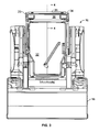
FIGURE 3 is a top elevation view of a cutaway of an embodiment of a work vehicle of the present invention; -
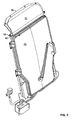
FIGURE 4 is a top perspective view of a cutaway of an embodiment of a work vehicle with a restraining device in a forward-adjusted position of the present invention; -
FIGURE 5 is a top perspective view of a cutaway of an embodiment of a work vehicle with a restraining device in an aft-adjusted position of the present invention; -
FIGURE 6 is a top elevation view of a cutaway of an embodiment of a work vehicle containing an operator disposed in a forward-adjusted position of the present invention; -
FIGURE 7 is a top elevation view of a cutaway of an embodiment of a work vehicle containing an operator disposed in an aft-adjusted position of the present invention. - In the drawings, like reference numerals refer to like parts throughout the several views.
-
FIGURE 1 shows anexemplary work vehicle 10 including aframe 12 that rotatably carries a plurality ofwheels 14. Animplement 18 including astructure 16 having an arrangement of structural members and actuators controllable by an operator (not shown) to manipulateimplement 18 to perform work is also connected toframe 12.Implement 18 includes, but is not limited to, brooms, augers, rakes, bales spikes, buckets, blades, hammers, forks, hoes, rock wheels, stump grinders and tillers. In an alternate embodiment,structure 16 may maintain implement 18 in a fixed or non-moving relationship withframe 12.Frame 12 structurally supports acab structure 20 to surround and protect the operator. Thecab structure 20 is configured to pivot with respect toframe 12.Frame 12 includes afront end 24 disposed proximate to implement 18.Front end 24 is disposed betweenopposed sides seat 28 is disposed interior ofcab structure 20 which is accessible via adoor 30.Door 30 is pivotably connected tocab structure 20, although in alternate embodiments, thedoor 30 may be slidably connected or in some other connective relationship with thecab structure 20. In further alternative embodiments, thedoor 30 may be deleted. As will be discussed in further detail below, a restraining device 48 is pivotably connected toframe 12 and/orcab structure 20 to pivot overseat 28 in an adjustable manner. - In one embodiment,
cab structure 20 pivots or rotates towardfront end 24. However, one having ordinary skill in the art can appreciate thatcab structure 20 may be configured to pivot or rotate in other directions. In other words,cab structure 20 may be configured to pivot or rotate in directions other than towardfront end 24, such as toward an opposite end 22 (FIGURE 2 ), or towardsides -
FIGURE 2 shows a top perspective rear view of theexemplary work vehicle 10 ofFIGURE 1 withcab structure 20 rotated away fromframe 12 andstructure 16 removed for clarity. As shown inFIGUREFIGURE 2,seat 28 is disposed between a pair of operator controls 42 that each includes arespective housing 44. As further shown,seat 28 includes abase 32 that is secured to the seat. In an alternate embodiment,base 32 andseat 28 are of unitary construction. -
FIGURE 3 shows a partial cutaway view ofwork vehicle 10 provided for clarity. As shown inFIGURE 3 , a pivoting connection 46 is disposed betweenbase 32 andframe 12. Pivoting connection 46 may be a hinge, a piano hinge, or other pivoting arrangement as would be appreciated by one of ordinary skill in the art. - As shown in
FIGURE 3 ,cab structure 20 includes apanel 34 that is disposed behindseat 28 whencab structure 20abuts frame 12.Panel 34 includes anupper portion 36 extending to amiddle portion 38 that further extends to alower portion 40 that is adjacent tobase 32 supportingseat 28. In alternate embodiments,panel 34 may be modified or otherwise deleted. Whencab structure 20 is rotated about pivoting connection 50,panel 34 is raised aboveseat 28. An operator restraining device 48 is pivotably secured toupper portion 36 to pivot overseat 28. In an alternate embodiment in whichpanel 34 is deleted, restraining device 48 is pivotably connected toframe 12. In another embodiment, restraining device 48 is pivotably connected toframe 12 andpanel 34. - To effect
cab structure 20 pivot or rotation,fasteners 60 securingupper portion 36 toframe 12 are loosened. An operator (not shown) may then place his feet on astep 54 disposed onstructure 16 and grasp hand rail 52 disposed along a vertical corner ofcab structure 20 and apply an opening force 62 to pivot or rotate thecab structure 20 in the direction indicated by arrow associated with opening force 62. When the operator applies the opening force 62, a strut 58 (FIGURE 1 ) extends, contributing an opening force along its length to help movecab structure 20 from a closed or operating position (FIGURE 1 ) to an open position (FIGURE 2 ). In one embodiment, the open position represents a predetermined degree of rotation X° (FIGURE 2 ) ofcab structure 20 between about 55 to about 60 degrees with respect to the frame 12 (FIGURE 2 ) as compared to the closed position (FIGURES 1 and3 ). - As further shown in
FIGURE 4 , restraining device 48 includes opposed L-shaped first portions 64 extending to armrests 66. A connecting member 68 is disposed between corresponding ends of armrests 66 opposite first portions 64. A unitary tube 70 extends through corresponding first portions 64, armrests 66 and connecting members 68. Tube 70 substantially spans the length of restraining device 48. Tube 70 may be covered with a layer of resilient material 74, such as by molding, to provide a contoured surface that is comfortable when in contact with the operator. In one embodiment, material 74 is applied by molding, although other processes may be used. Ends of first portions 64 opposite armrests 66 are pivotably connected to corresponding pivoting brackets 72. Pivoting brackets 72 include a pivot 80 for providing a pivotable connection with restraining device 48. Pivoting brackets 72 further include a plurality of apertures 82 that are aligned with corresponding openings 88 of a bracket 86 connected toupper portion 36 ofpanel 34 for receiving fasteners 84 therethrough. As further shown inFIGURE 4 , pivoting bracket 72, and therefore the pivotable connection, is disposed in a forward-adjusted position with respect toseat 28. In contrast,FIGURE 5 shows pivoting bracket 72 disposed in an aft-adjusted position with respect toseat 28. - As also shown in
FIGURE 4 , pivoting brackets 72 include a row of horizontally disposed apertures 82, and brackets 86 include a horizontally disposed row of openings 88. However in alternate embodiments, those skilled in the art can appreciated that either or both of pivoting brackets 72 and brackets 86 may include corresponding vertically disposed apertures 82 and openings 88. This combination of vertical and/or horizontal adjustment of pivot 80 provides an adjustable pivoting connection for enhanced operator comfort, accommodating for a considerable range of different operator sizes, as well as accommodating unique comfort adjustment preferences for the operators. More specifically, the adjustable pivoting connection permits use of a single construction of restraining device 48 that may save inventory costs. - As shown in
FIGURE 4 , a strut 76 is pivotably disposed between tube 70 along first portion 64 andmiddle portion 38 ofpanel 34. Strut 76 is shown in a compressed position, providing an opening force to assist the operator in raising restraining device 48. - As shown in
FIGURE 5 , a pair of stops 78, 90 provide additional adjustment for restraining device 48 to further provide enhanced operator comfort. Stops 78, 90 adjustably extend frommiddle portion 38 ofpanel 34, contacting the junction between first portion 64 and armrest 66. Stop 78 is shown in an extended position, while stop 90 is shown in a substantially retracted position. Each stop 78, 90 includes a contact 98 that is secured to a threaded shaft 100 and a threaded insert (not shown) disposed behindmiddle portion 38. A locking device 102 is threadedly engaged with shaft 100. To effect desired adjustment of stop 78, 90, contact 98 is rotated in one direction until contact 98 extends a selected distance frommiddle portion 38. Rotation of locking device 102 in one direction, which as shown is a knob for ease of rotational manipulation, urges locking device 102 to move with respect to contact 98 towardmiddle portion 38, acting as a lock nut. Rotation of locking device 102 in the other direction urges locking device 102 to a loosened position, permitting rotational adjustment of threaded shaft 100 to adjust the position of contact 98 with respect tomiddle portion 38. - In response to extending stops 78, 90 away from
middle portion 38 while maintaining pivoting brackets 72 in respective fixed positions, stops 78, 90 act as a fulcrum with respect to restraining device 48 and pivoting bracket 72. That is, armrests 66 are correspondingly raised to a position to enhance operator comfort. In other words, once pivoting bracket 72 has been mounted, each stop 78, 90 is configured to limit pivoting travel of each armrest 66 to a predetermined lowered position. In the exemplary embodiment, to the extent permitted by restraining device 48, and as shown inFIGURE 4 , stops 78, 90 may be independently adjusted so that the ends of the armrests 66 may be raised to different levels. In an alternate embodiment in which tube 70 does not extend through connecting member 68, the extent or adjustability may be further increased. - As shown in
FIGURE 5 , a sensor 92 is disposed in close proximity of the pivotable connection to indicate when the restraining device 48 is disposed in an operating position. A tab 94 contacts a plunger or other portion of sensor 92 to indicate when the restraining device 48 is disposed in an operating position. Sensor 92 may be connected with the ignition system of the work vehicle, preventing operation of the work vehicle until sensor 92 actuated by tab 94. In alternate embodiments, other arrangements may be used or the sensor 92 may be deleted. - In an alternate embodiment, it is to be understood that stops 78, 90, or a single stop may be disposed along different portions of restraining device 48, so long as the position of stops armrests 66 are adjustable.
- It is also to be understood that the length of portions of restraining device 48 may also be adjustable. For example, each first portion 64 and armrest 66 may include an adjustable construction, such as a turnbuckle or concentrically slidably disposed tubes with associated apertures formed to receive a pin, not shown, although other constructions may be used.
- It is also to be understood that a harness may also be used in addition to restraining device 48, although, such harness is typically undesirable, due to the additional heat generated by contact with the operator.
- While not specifically shown in the exemplary embodiment, the adjustable pivoting connection also accommodates either of two different constructions of operator controls 42 configured for use with the
work vehicle 10. One construction, referred to as mechanical controls, makes use of mechanical linkages to control the operation of the work vehicle, having a predetermined range of forward/aft adjustment from a home position shown in the FIGURES. For example, in one embodiment, the predetermined range is about 13.25 inches, although in other embodiments, the predetermined range may be greater than or less than this amount. Another construction, referred to as pilot controls, makes use of hydraulics to control the operation of the work vehicle, having a predetermined range of forward/aft adjustment from a home position shown in the FIGURES. For an example, in one embodiment, the predetermined range is about 5.25 inches, although in other embodiments, the predetermined range may be greater than or less than this amount. It is appreciated by those skilled in the art that the adjustable pivoting connection permits use of a single construction of restraining device 48 with use of either operator controls 42 construction. For example, as shown inFIGURE 6 , an operator 96 grasps operator controls 42 with restraining device 48 disposed in a forward-adjusted position similar toFIGURE 4 . Similarly, as shown inFIGURE 7 , operator 96 grasps operator controls 42 with restraining device 48 disposed in an aft-adjusted position similar toFIGURE 5 . By virtue of the different amount of armrest 66 support provided to operator 96, a position of comfort may be achieved for any combination of operator size, operator controls 42 construction, as well as unique preferences by the operator. - While the invention has been described with reference to a preferred embodiment, it will be understood by those skilled in the art that various changes may be made and equivalents may be substituted for elements thereof without departing from the scope of the invention. In addition, many modifications may be made to adapt a particular situation or material to the teachings of the invention without departing from the essential scope thereof. Therefore, it is intended that the invention not be limited to the particular embodiment disclosed as the best mode contemplated for carrying out this invention, but that the invention will include all embodiments falling within the scope of the appended claims.
Claims (13)
- A work vehicle (10) comprising:a frame (12);a cab structure (20) connected to said frame (12);a seat (28) connected to said frame (12); anda substantially rigid restraining device (48) of unitary construction pivotably connected behind said seat (28) to any one of said frame (12), said cab structure (20), or said frame (12) and said cab structure (20); andcharacterized in that said pivotable connection between said restraining device (48) and said frame (12) and/or said cab structure (20) is adjustable.
- A work vehicle (10) according to claim 1, characterized in that said cab structure (20) and said seat (28) are each pivotably connected to said frame (12).
- A work vehicle (10) according to claim 1 or 2, characterized in that said restraining device (48) is configured to pivot over said seat (28).
- A work vehicle (10) according to any of the preceding claims, characterized in that a sensor (92) is disposed in close proximity of said pivotable connection to indicate when said restraining device (48) is disposed in an operating position.
- A work vehicle (10) according to any of the preceding claims, characterized in that said pivotable connection is adjustable in a horizontal direction.
- A work vehicle (10) according to claim 5, characterized in that said pivotable connection is adjustable in a both a vertical and a horizontal direction.
- A work vehicle (10) according to any of the preceding claims, characterized in that said restraining device (48) is substantially covered by a layer of material (74) forming a contoured surface.
- A work vehicle according to claim 7, characterized in that said material (74) is molded to said restraining device (48).
- A work vehicle (10) according to any of the preceding claims, characterized in that said restraining device (48) includes a tube (70) substantially spanning the length of said restraining device (48).
- A work vehicle (10) according to any of the preceding claims, characterized in that said restraining device (48) includes an armrest (66).
- A work vehicle (10) according to claims 10, characterized in that a stop (78, 90) is configured to limit pivoting travel of said armrest (66) to a predetermined lowered position.
- A work vehicle (10) according to claim 11, characterized in that said stop (78, 90) is manually adjustable.
- A work vehicle (10) according to claim 10 or 11, characterized in that each stop (78, 90) of a pair of stops (78, 90) is configured to limit pivoting travel of each armrest (66) to a predetermined lowered position.
Applications Claiming Priority (1)
| Application Number | Priority Date | Filing Date | Title |
|---|---|---|---|
| US12/023,434 US7677647B2 (en) | 2008-01-31 | 2008-01-31 | Adjustable mounting restraint device |
Publications (2)
| Publication Number | Publication Date |
|---|---|
| EP2085524A2 true EP2085524A2 (en) | 2009-08-05 |
| EP2085524A3 EP2085524A3 (en) | 2017-04-19 |
Family
ID=40451174
Family Applications (1)
| Application Number | Title | Priority Date | Filing Date |
|---|---|---|---|
| EP09151696.3A Withdrawn EP2085524A3 (en) | 2008-01-31 | 2009-01-30 | Adjustable mounting restraint device. |
Country Status (2)
| Country | Link |
|---|---|
| US (1) | US7677647B2 (en) |
| EP (1) | EP2085524A3 (en) |
Families Citing this family (7)
| Publication number | Priority date | Publication date | Assignee | Title |
|---|---|---|---|---|
| WO2008115461A2 (en) | 2007-03-16 | 2008-09-25 | Polaris Industries Inc. | Vehicle |
| US7731273B2 (en) * | 2008-01-31 | 2010-06-08 | Cnh America Llc | Work vehicle viewing system |
| WO2010134152A1 (en) * | 2009-05-18 | 2010-11-25 | トヨタ自動車株式会社 | Vehicle controller |
| JP6211344B2 (en) * | 2013-08-12 | 2017-10-11 | 住友建機株式会社 | Excavator |
| SE539198C2 (en) * | 2015-09-09 | 2017-05-09 | BAE Systems Hägglunds AB | Vehicle frame for a tracked amphibious vehicle |
| EP3450386B1 (en) | 2017-09-01 | 2024-11-13 | Palfinger AG | Forklift |
| DE202017005064U1 (en) * | 2017-09-28 | 2019-01-02 | HSM Hans Sauermann GmbH & Co. KG | Restraint system for a driver of a vehicle |
Family Cites Families (15)
| Publication number | Priority date | Publication date | Assignee | Title |
|---|---|---|---|---|
| US296975A (en) * | 1884-04-15 | Safety-brace for car-seats | ||
| US3165333A (en) * | 1963-02-12 | 1965-01-12 | Earl H Dalgleish | Adjustable passenger safety guard |
| US4509798A (en) * | 1982-08-23 | 1985-04-09 | John Strothers | Vehicle seat harness |
| US4537446A (en) * | 1983-08-04 | 1985-08-27 | Clark Equipment Company | Safety seat |
| US4813746A (en) * | 1987-08-27 | 1989-03-21 | Mulholland Designs, Inc. | Wheelchair pelvic support arms |
| US5050700A (en) * | 1989-06-05 | 1991-09-24 | Daewoo Heavy Industries Ltd. | Safety apparatus for a skid-steer loader |
| DE3929957C2 (en) | 1989-09-08 | 1994-01-13 | Schmitz Gmbh & Co | Seat for a means of transport, in particular for a motor vehicle |
| US5655817A (en) * | 1994-07-29 | 1997-08-12 | Nienow; Joseph R. | Secure seat |
| US5607203A (en) * | 1995-11-10 | 1997-03-04 | Century Products Company | Child's car seat with improved overhead shield |
| US20020076314A1 (en) * | 2000-12-18 | 2002-06-20 | Zanetis C. Christopher | Towable work vehicle |
| US6732829B2 (en) * | 2002-01-04 | 2004-05-11 | Clark Equipment Company | Load absorbing operator restraint bar |
| DE10236447A1 (en) * | 2002-08-08 | 2004-02-19 | Still Gmbh | Safety belt system for fork-lift truck comprises cable attached to top of seat belt and tensioning roller attached to top of the cable whose position can be adjusted by driver moving transverse bar above driving seat |
| US6902024B2 (en) * | 2002-11-27 | 2005-06-07 | Clark Equipment Company | Lateral operator restraint system and position sensor for material handler |
| US7396070B2 (en) * | 2004-05-26 | 2008-07-08 | Clark Equipment Company | Relocatable position operator seat station for loader |
| US7757806B2 (en) * | 2005-12-22 | 2010-07-20 | Caterpillar Sarl | Adjustable operator interface |
-
2008
- 2008-01-31 US US12/023,434 patent/US7677647B2/en active Active
-
2009
- 2009-01-30 EP EP09151696.3A patent/EP2085524A3/en not_active Withdrawn
Non-Patent Citations (1)
| Title |
|---|
| None * |
Also Published As
| Publication number | Publication date |
|---|---|
| US7677647B2 (en) | 2010-03-16 |
| US20090195024A1 (en) | 2009-08-06 |
| EP2085524A3 (en) | 2017-04-19 |
Similar Documents
| Publication | Publication Date | Title |
|---|---|---|
| US7677647B2 (en) | Adjustable mounting restraint device | |
| US8167080B2 (en) | Grader controls at armrest | |
| EP1288063B1 (en) | Utility vehicle | |
| JP4767966B2 (en) | Folding armrest | |
| US7971677B2 (en) | Work machine vehicle having seat mounted controls with nested seatbar | |
| EP2143624B1 (en) | Vehicle seat and split console assembly | |
| US5613404A (en) | Tiltable steering mechanism for an off-highway implement | |
| CN112601676B (en) | Work vehicle | |
| US20020145325A1 (en) | Armrest structure | |
| US10000244B2 (en) | Tiltable cabin | |
| US7389845B2 (en) | Machine control apparatus and method | |
| US20030112583A1 (en) | Apparatus for adjusting a height of control boxes | |
| US9579994B2 (en) | Adjustable seat support | |
| US4930593A (en) | Pivoting seat structure for a front mounted mower | |
| US6550560B2 (en) | Control handle pivot apparatus | |
| EP1966027A1 (en) | Cab structure for a vehicle | |
| JP5065473B2 (en) | Armrest device for construction machinery | |
| CN205100269U (en) | A auxiliary control pole system and operator's driver's cabin for machine | |
| US8069927B2 (en) | Rear-mounted work implement control system | |
| US20040168421A1 (en) | Convertible support | |
| JP2006103423A (en) | Horizontal control device for seat | |
| KR101630455B1 (en) | Console Box Elevating Device for The Driver's Seat of Construction Machinery | |
| JPH11225534A (en) | Tractor mower lifting device | |
| JPH078377Y2 (en) | Seat height adjustment device for tilt fender type tractor | |
| JP2022114942A (en) | work machine |
Legal Events
| Date | Code | Title | Description |
|---|---|---|---|
| PUAI | Public reference made under article 153(3) epc to a published international application that has entered the european phase |
Free format text: ORIGINAL CODE: 0009012 |
|
| AK | Designated contracting states |
Kind code of ref document: A2 Designated state(s): AT BE BG CH CY CZ DE DK EE ES FI FR GB GR HR HU IE IS IT LI LT LU LV MC MK MT NL NO PL PT RO SE SI SK TR |
|
| AX | Request for extension of the european patent |
Extension state: AL BA RS |
|
| RAP1 | Party data changed (applicant data changed or rights of an application transferred) |
Owner name: CNH ITALIA S.P.A. |
|
| RAP1 | Party data changed (applicant data changed or rights of an application transferred) |
Owner name: CNH ITALIA S.P.A. |
|
| RAP1 | Party data changed (applicant data changed or rights of an application transferred) |
Owner name: CNH INDUSTRIAL ITALIA S.P.A. |
|
| PUAL | Search report despatched |
Free format text: ORIGINAL CODE: 0009013 |
|
| AK | Designated contracting states |
Kind code of ref document: A3 Designated state(s): AT BE BG CH CY CZ DE DK EE ES FI FR GB GR HR HU IE IS IT LI LT LU LV MC MK MT NL NO PL PT RO SE SI SK TR |
|
| AX | Request for extension of the european patent |
Extension state: AL BA RS |
|
| RIC1 | Information provided on ipc code assigned before grant |
Ipc: E02F 9/16 20060101ALI20170313BHEP Ipc: B62D 33/067 20060101ALI20170313BHEP Ipc: E02F 9/24 20060101AFI20170313BHEP Ipc: B60R 21/02 20060101ALI20170313BHEP |
|
| 17P | Request for examination filed |
Effective date: 20171019 |
|
| RBV | Designated contracting states (corrected) |
Designated state(s): AT BE BG CH CY CZ DE DK EE ES FI FR GB GR HR HU IE IS IT LI LT LU LV MC MK MT NL NO PL PT RO SE SI SK TR |
|
| AKX | Designation fees paid |
Designated state(s): AT BE BG CH CY CZ DE DK EE ES FI FR GB GR HR HU IE IS IT LI LT LU LV MC MK MT NL NO PL PT RO SE SI SK TR |
|
| AXX | Extension fees paid |
Extension state: RS Extension state: BA Extension state: AL |
|
| 17Q | First examination report despatched |
Effective date: 20171222 |
|
| STAA | Information on the status of an ep patent application or granted ep patent |
Free format text: STATUS: THE APPLICATION IS DEEMED TO BE WITHDRAWN |
|
| 18D | Application deemed to be withdrawn |
Effective date: 20180503 |