EP2085301A1 - Locking device - Google Patents
Locking device Download PDFInfo
- Publication number
- EP2085301A1 EP2085301A1 EP09290076A EP09290076A EP2085301A1 EP 2085301 A1 EP2085301 A1 EP 2085301A1 EP 09290076 A EP09290076 A EP 09290076A EP 09290076 A EP09290076 A EP 09290076A EP 2085301 A1 EP2085301 A1 EP 2085301A1
- Authority
- EP
- European Patent Office
- Prior art keywords
- locking
- lock
- locking member
- cycle
- housing
- Prior art date
- Legal status (The legal status is an assumption and is not a legal conclusion. Google has not performed a legal analysis and makes no representation as to the accuracy of the status listed.)
- Granted
Links
Images


Classifications
-
- B—PERFORMING OPERATIONS; TRANSPORTING
- B62—LAND VEHICLES FOR TRAVELLING OTHERWISE THAN ON RAILS
- B62H—CYCLE STANDS; SUPPORTS OR HOLDERS FOR PARKING OR STORING CYCLES; APPLIANCES PREVENTING OR INDICATING UNAUTHORIZED USE OR THEFT OF CYCLES; LOCKS INTEGRAL WITH CYCLES; DEVICES FOR LEARNING TO RIDE CYCLES
- B62H5/00—Appliances preventing or indicating unauthorised use or theft of cycles; Locks integral with cycles
- B62H5/003—Appliances preventing or indicating unauthorised use or theft of cycles; Locks integral with cycles using chains or cables
-
- B—PERFORMING OPERATIONS; TRANSPORTING
- B62—LAND VEHICLES FOR TRAVELLING OTHERWISE THAN ON RAILS
- B62H—CYCLE STANDS; SUPPORTS OR HOLDERS FOR PARKING OR STORING CYCLES; APPLIANCES PREVENTING OR INDICATING UNAUTHORIZED USE OR THEFT OF CYCLES; LOCKS INTEGRAL WITH CYCLES; DEVICES FOR LEARNING TO RIDE CYCLES
- B62H3/00—Separate supports or holders for parking or storing cycles
-
- B—PERFORMING OPERATIONS; TRANSPORTING
- B62—LAND VEHICLES FOR TRAVELLING OTHERWISE THAN ON RAILS
- B62H—CYCLE STANDS; SUPPORTS OR HOLDERS FOR PARKING OR STORING CYCLES; APPLIANCES PREVENTING OR INDICATING UNAUTHORIZED USE OR THEFT OF CYCLES; LOCKS INTEGRAL WITH CYCLES; DEVICES FOR LEARNING TO RIDE CYCLES
- B62H5/00—Appliances preventing or indicating unauthorised use or theft of cycles; Locks integral with cycles
Definitions
- the invention relates to the field of cycle storage.
- the invention relates more particularly to a locking device for the anti-theft function.
- the cycles proposed for rental are stored on fixing terminals for example by a striker blocking or releasing a fastening device attached to a cycle.
- a cycle is thus used by a user after the user has released the cycle of its attachment terminal.
- the time of use until a new attachment to a docking station, possibly for billing, can be controlled.
- a cycle can also be attached by an antitheft device.
- the cycles proposed for rental are notably equipped with an antitheft device secured to the frame of the cycle, allowing for example a user to park the cycle during a short stop.
- a problem of the cycle storage systems each equipped with a lock is in particular to prevent a user to block a cycle on its storage terminal with the lock on the cycle.
- the patent application EP 1 820 722 teaches, for example, a system comprising stationary locking stations, each locking station being equipped with a keeper for receiving a locking member attached to the cycle.
- Each cycle comprises in particular a lock formed by a flexible link attached to the cycle, the link having at its end a pin that can be inserted into a receiving housing disposed adjacent to the locking member.
- the receiving housing of the spindle is also arranged forward with respect to the locking member, in the insertion direction of the locking member in the striker.
- the locking device when inserted into the latch of the locking station, prevents inserting the pin of the lock in its housing.
- this system can not protect the key of the lock against a malicious user wanting to steal the key.
- a user can indeed easily unblock the receiving slot of the lock pin, for example using a straight metal rod, to remove the key from its slot.
- the cycle can be hung again on a storage terminal, by the malicious user who is not then concerned.
- a cycle storage system could thus be rapidly deteriorated. There is therefore a need to protect a storage system from the cycles against the theft of keys on cycle locks.
- the present invention aims to overcome one or more disadvantages of the prior art, by providing a locking device performing a hooking function with a terminal and a locking function of a housing that can accommodate, for example, a mouthpiece burglar.
- the device comprises a lock comprising a cable attached to the cycle and ending at one end by a tip, the housing receiving the end of the cable, the end piece being inserted or removed from the housing by the opening of access.
- the housing has a determined depth and comprises a wall facing a projecting axis having an axis of symmetry, the tip being made of annular shape, of internal diameter greater than the diameter of the projecting axis, of outer diameter less than twice the distance between the wall of the axis of symmetry of the projecting axis and of thickness less than the depth of the housing.
- the key remains locked in the lock in unlocked positions of the lock, the lock comprising a movable lock rotating with the key and cooperating with an internal body member, this internal member being movable with the body of the lock. locking or locking the locking member when the lock of the lock blocks this internal member.
- the internal member comprises an internal axis guided in rotation in the body and secured to the locking member, the internal axis comprising at least one slot or a notch for cooperation with the lock, the storage position corresponding to a position of the locking member disposed towards the front of the cycle, the locking position of the access opening corresponding to a position of the locking member arranged at the top, bottom or back of the cycle.
- the locking member comprises a guide plate in the striker, the guide plate being joined in its middle by a perpendicular portion comprising a recess or a notch or a locking nose in the striker.
- the present invention also aims to overcome one or more disadvantages of the prior art, by providing a cycle storage system each equipped with a locking device performing a hooking function with a terminal and a blocking function. a housing that can accommodate, for example, an anti-theft tip.
- a storage system for at least one cycle equipped with a locking device characterized in that it comprises at least one attachment terminal comprising a striker allowing a fastening of the organ locking in a determined position of the locking member separate from its blocking position of the access opening to the housing.
- the storage system comprises a management component comprising a user interface communicating with an identification or payment module enabling the activation of a control module for unblocking said latch of said terminal, the module activated unlock control being driven by the user interface.
- a cycle storage system installed for example in an urban environment, comprises for example several fixed terminals, arranged for example in a parking space or on a sidewalk.
- Each terminal is, for example, equipped with a latching strike and holding for a locking member attached to a cycle.
- the cycle is for example maintained at the terminal until a user controls the terminal to release the locking member to use the cycle.
- a management component controlling the terminals will, for example, be described later.
- the striker comprises one or more guiding surfaces of the locking member (3), guiding a latching part of the locking member (3) towards a fastening member of the striker.
- the latching member of the striker comprises, for example, a hook or a spout or a movable latch resiliently held in the locked position.
- An electromagnetic control makes it possible, for example, to unlock the attachment member of the striker.
- the attachment portion of the locking member (3) comprises, for example, a recess or a spout or a notch or a slot or a groove cooperating with the hooking member of the keeper.
- the locking device comprises a body (1) attached to the cycle.
- the body is fixed, in a nonlimiting manner, by clamping, screwing or welding cycle.
- the body comprises for example a rounded surface (S1) coming against a bar of the frame of the cycle.
- a clamp or a complementary rounded portion allows for example a clamping of the frame bar against the body (1) of the locking device.
- the body (1) is, for example, connected, in a non-limiting manner to the opposite of the bearing surface (S1), to the movable locking member (3) relative to the body (1).
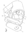
- This locking member (3) is for example positioned, with respect to the body (1), in a storage position, as shown in FIGS. Figures 5 and 6 .
- the storage position allows for example the maintenance of the locking member (3) in the striker of a terminal.
- the locking member may comprise one or more storage positions.
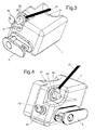
- the locking member (3) can also be positioned, relative to the body, in a locking position of an access opening to a housing, as shown in FIGS. Figures 1 and 2 .
- the locking member may comprise one or more locking positions.
- the body (1) may also include one or more dwellings.
- the body (1) further comprises a lock (41) activated by a key (42).
- the lock (41) may be disposed on a face adjacent to the face connected to the locking member (3) or on a face opposite the locking member.
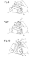
- the lock can also be arranged on the body (1) on the same side as the locking member (3) and in a recess formed in the body (1), as shown in FIGS. Figures 8 to 9 .
- the locking member (3) in the storage position can be arranged in front of the key (42), as shown in FIG. figure 8 , thus preventing the key (42) from being pulled.
- the locking member (3) can thus firstly block the access opening to the housing receiving, for example, the tip of the lock and secondly the member (3) of movable lock can realize, in its storage position, blocking access to the key.
- the lock comprises for example a hook or a latch (43) or a bolt cooperating with a member (31) internal to the body (1) secured to the member (3) locking.
- the internal member (31) is for example connected to the locking member (3) to be movable or blocked relative to the body (1), at the same time as the locking member (3).
- the internal organ (31) comprises, for example, a notch or a slot or a groove or a flat part (32) cooperating with the lock, allowing locking of the lock and locking of the internal member (31) and the locking member (3). located in a blocking position, as shown in Figures 13 and 14 .
- locking the lock causes the locking member to be held in the locking position.
- the internal member (31) is in a position which does not allow locking of the lock.
- the lock cooperates with the member (31) internal to the body (1) and connected to the locking member (3), this internal member not being accessible from outside the body.
- the internal member is for example an axis guided in rotation in the body (1) and comprising, for example, a longitudinal groove or a flat (31) cooperating, for example, with a bolt or a lock (43) of the lock .
- the axis is for example secured to the locking member (3).
- the groove or the flat part (32) of the internal member (31) is for example positioned at a given angle to come opposite the lock of the lock, when the locking member is in a blocking position of the opening access to housing, as represented at figure 2 .
- the Figures 11 and 12 represent, for example, the same storage position of a locking device.
- the figure 12 represents a view from the outside and the figure 11 represents the internal elements of the locking device.
- the locking member (3) is, for example, almost horizontal, the internal member (31) having, for example, its flats (32) downwards. In a nonlimiting manner, an abutment (33) internal comes against the flat (32) so as to prevent rotation of the member (3) locking downwards relative to its storage position.
- This position of the lock corresponds, for example, to an unlocked position in which the key can not be removed.
- the Figures 13 and 14 represent, a same locking position of the locking device represented in the storage position at Figures 11 and 12 .
- the figure 14 represents a view from the outside and the figure 13 represents the internal elements of the locking device.
- the locking member (3) is, for example against the end of the portion (52) projecting forming the housing, so as to block the access opening to the housing.
- the latch (43) is for example pivoted to come against the flat (32).
- the flat is, on the other hand, bearing against the abutment (33) internal limiting the rotational movement of the member (31) internal secured to the member (3) locking.
- This position of the lock (41) corresponds, for example, to a locked position, in which the (42) key can be removed.
- the key (42) can be removed from the lock (41) only when the lock is locked, the key remaining locked in the lock when the lock is not in the locked position.
- the lock remains in the unlocked position when the locking member (3) is not in the locking position and the key can not be removed without arranging the locking member in the locking position.
- a locking position is in particular distinct and incompatible with a storage position.
- the antitheft device comprises for example a cable (21) attached to the cycle, for example, by one end.
- the cable of the antitheft device comprises, for example, at its other end, the tip (20) can be put in the housing.
- the insertion of a nozzle into the housing is, for example, shown in Figures 3 and 4 and the end piece (20) blocked in the housing is, for example, shown in FIGS. Figures 1 and 2 .
- the cable is for example passed around a tree or around a pole or in the wheels and the frame of the cycle to immobilize the cycle.
- a user To be able to place the locking member in the storage position, a user must then unlock the lock, for example by inserting the key in the lock and unlocking the lock.
- An electrically controlled lock can also be used.
- the organ of lock positioned in a position other than a blocking position then prevents the locking of the lock and thus prevents the key from being removed.
- the locking member (3) disposed in a locking position completely or at least partially blocks the access opening, so that the end piece can no longer be removed from the housing.
- the housing may in particular be made by a wall (51) forming a cylindrical portion, disposed opposite a cylindrical axis (52) salient.
- the locking member (3) in its locking position, comes for example in front of the space between the wall (51) and the axis (52).
- An antitheft device comprises for example a ferrule (20) in the form of a ring coming round the axis (52) protruding cylindrical.
- this open housing on each side can also receive a chain or a cable attached at both ends to a building or a pole.
- the housing can be used to fix the cycle to an element of the urban environment, such as a chain or a straight bar or rounded.
- the housing may in fact comprise a flat wall (53) disposed opposite a protruding part (52), for example cylindrical, the space between the projecting element and the wall of the body being blocked, for example, to receive a fixed bar of an element of the urban environment.
- the housing may be hollowed out in the body (1) or the projecting element may be made protruding and coming opposite a surface (53) of the body, as shown in FIGS. Figures 7 to 10 .
- the housing may also comprise a cylindrical space opened by the access opening and in a nonlimiting manner, by a lateral slot through which the anti-theft cable passes.
- the anti-theft tip is, for example made of spherical shape or with a minimum height determined.
- the cylindrical housing does not include a side slot, the access opening is for example blocked only in part to let the cable of the lock while preventing the extraction of the spherical tip. If the locking member (3) completely closes the access opening, the slot then allows the passage of the cable of the lock.
- the housing comprises, for example, a cylindrical inner space of a determined diameter greater than the outer diameter of the spherical tip.
- the slot is of predetermined width greater than the thickness of the cable to allow the passage of the cable. The width of the slot is on the other hand less than the thickness or height of the tip to block the tip.
- a second housing comprises an opening for insertion or extraction of an immobilizing element, this opening being able to be locked by the locking member, for example in a second locking position.
- the locking member is for example formed in the form of a member comprising two vertical lateral guide plates on each side of a striker.
- the side plates are, for example, linked in their middle to a perpendicular plate including a recess for the passage of the beak of the striker.
- the perpendicular plate is for example arranged almost horizontally in the storage position in which the locking member is held in the keeper.
- a rotation of the locking member allows for example a positioning to block the access opening of the housing.
- a rotation between a storage position and a locking position is performed at 90 ° or 180 ° or at another angle such that the access opening to the housing is released when the locking member is in its storage position.
- a locking member may also be connected by a ball joint to the body (1).
- the ball held in the body (1) comprises for example a or more slots for insertion of a hook or bolt of the lock in the locking position or positions.
- the orientation can be adjusted in three axes of rotation, while the slot in the ball makes it possible to determine a precise blocking position.
- the locking member may also be in the form of a finger, for example cylindrical with a peripheral groove cooperating with the locking member of the striker.
- a finger or a bar can thus be used to block the opening of the housing.
- the end of the locking member (3) can also be made to cooperate both with the striker and with a body part (1) in its locking position.
- a spout is for example locked in the striker or resting in a notch of the body (1) in the locking position.
- the beak locked in the body when the locking member is in the locking position provides for example greater rigidity and better resistance for blocking the opening of the housing.
- the end of the fastening member housed in the body no longer makes it possible to snap into a strike of a terminal
- the hanging during storage can be achieved in different ways, the positioning of the locking member in a storage position that can be varied.
- the locking device thus allows very diverse uses.
- An attachment for storage may for example also be prevented by a projecting portion of the body (1) disposed in the extension of the locking member in its locking position. This protruding part allows for example to abut against the striker to prevent attachment of the locking member in the striker, in a locking position.
- a determined locking position of the locking member for example towards the rear of the cycle, can also make it possible to prevent a catch in the striker thanks to the congestion of the cycle or to prohibited positions of the cycle.
- a storage terminal is for example controlled by a computer management component that includes a user interface for a user to activate a payment module or identification. After the payment or the success of a user identification, a registration of the references of the user is, for example realized in the management component. After registering the user references, for example, a terminal control module is activated. The control module transmits for example to an interface manager module data representative of a controlled terminal in an unlocked position, while the strike of the terminal is controlled in the unlocking position. An identifier of the cycle is, for example, stored in association with the references of the user.
- An electric power circuit is for example controlled by a logic electronic signal transmitted by the management component.
- a control interface of the power circuit is, for example, controlled by the terminal control module.
- an identification of the cycle is for example carried out by the terminal.
- the terminal is for example equipped with a reader to read an identifier of the cycle.
- the terminal comprises for example an optical reader for a code inscribed on the cycle.
- the terminal may also include a radio frequency reader for identifying a radio frequency chip disposed in the cycle.
- the terminal may also include an electronic reader by contact for reading an identifier stored in a chip powered and communicating by contact pads.
- the identifier of the cycle is for example controlled to update a database comprising data representative of identifiers of the cycles associated with a used or available state and user references of the cycles used. For example, several management components communicate with the database to manage a plurality of parks each comprising a management component and a plurality of cycle storage terminals.
Abstract
Description
L'invention concerne le domaine du stockage de cycles. L'invention concerne plus particulièrement un dispositif de verrouillage permettant la fonction antivol.The invention relates to the field of cycle storage. The invention relates more particularly to a locking device for the anti-theft function.
Les cycles proposés à la location sont stockés sur des bornes de fixation par exemple par une gâche bloquant ou libérant un dispositif d'accrochage fixé sur un cycle. Un cycle est ainsi utilisé par un usager après que l'usager a libéré le cycle de sa borne d'accrochage. Le temps d'utilisation jusqu'à une nouvelle fixation à une borne d'accrochage, éventuellement pour une facturation, peut ainsi être contrôlé. Au cours d'une période d'utilisation du cycle par un usager, un cycle peut aussi être attaché par un dispositif antivol. Les cycles proposés à la location sont notamment équipés d'un dispositif antivol solidarisé au cadre du cycle, permettant par exemple à un usager de stationner le cycle lors d'un arrêt court.The cycles proposed for rental are stored on fixing terminals for example by a striker blocking or releasing a fastening device attached to a cycle. A cycle is thus used by a user after the user has released the cycle of its attachment terminal. The time of use until a new attachment to a docking station, possibly for billing, can be controlled. During a period of use of the cycle by a user, a cycle can also be attached by an antitheft device. The cycles proposed for rental are notably equipped with an antitheft device secured to the frame of the cycle, allowing for example a user to park the cycle during a short stop.
Un problème des systèmes de stockage de cycles équipés chacun d'un antivol, est notamment d'empêcher un utilisateur de bloquer un cycle sur sa borne de stockage avec l'antivol équipant le cycle. La demande de brevet
La présente invention a pour objet de pallier un ou plusieurs inconvénients de l'art antérieur, en proposant un dispositif de verrouillage réalisant une fonction d'accrochage avec une borne et une fonction de blocage d'un logement pouvant accueillir, par exemple, un embout d'antivol.The present invention aims to overcome one or more disadvantages of the prior art, by providing a locking device performing a hooking function with a terminal and a locking function of a housing that can accommodate, for example, a mouthpiece burglar.
Cet objectif est atteint grâce à un dispositif de verrouillage comprenant :
- un corps fixé à un cycle, le corps étant lié avec un organe de verrouillage ayant au moins une position déterminée de stockage dans laquelle l'organe de verrouillage peut être bloqué dans une gâche d'une borne de stockage du cycle,
- une clé actionnant une serrure disposée dans le corps,
- a body fixed to a cycle, the body being connected with a locking member having at least one determined storage position in which the locking member can be locked in a keeper of a storage terminal of the cycle,
- a key actuating a lock disposed in the body,
Selon une autre particularité, le dispositif comprend un antivol comprenant un câble fixé au cycle et se terminant à une extrémité par un embout, le logement recevant l'embout du câble, l'embout étant inséré ou retiré du logement par l'ouverture d'accès.According to another feature, the device comprises a lock comprising a cable attached to the cycle and ending at one end by a tip, the housing receiving the end of the cable, the end piece being inserted or removed from the housing by the opening of access.
Selon une autre particularité, le logement a une profondeur déterminée et comprend une paroi en face d'un axe saillant ayant un axe de symétrie, l'embout étant réalisé de forme annulaire, de diamètre intérieur supérieur au diamètre de l'axe saillant, de diamètre extérieur inférieur au double de la distance séparant la paroi de l'axe de symétrie de l'axe saillant et d'épaisseur inférieure à la profondeur du logement.According to another feature, the housing has a determined depth and comprises a wall facing a projecting axis having an axis of symmetry, the tip being made of annular shape, of internal diameter greater than the diameter of the projecting axis, of outer diameter less than twice the distance between the wall of the axis of symmetry of the projecting axis and of thickness less than the depth of the housing.
Selon une autre particularité, la clé reste bloquée dans la serrure dans des positions non verrouillées de la serrure, la serrure comprenant un verrou mobile tournant avec la clé et coopérant avec un organe interne au corps, cet organe interne étant mobile avec l'organe de verrouillage ou bloquant l'organe de verrouillage lorsque le verrou de la serrure bloque cet organe interne.According to another particularity, the key remains locked in the lock in unlocked positions of the lock, the lock comprising a movable lock rotating with the key and cooperating with an internal body member, this internal member being movable with the body of the lock. locking or locking the locking member when the lock of the lock blocks this internal member.
Selon une autre particularité, l'organe interne comprend un axe interne guidé en rotation dans le corps et solidarisé avec l'organe de verrouillage, l'axe interne comprenant au moins une fente ou une encoche de coopération avec le verrou, la position de stockage correspondant à une position de l'organe de verrouillage disposé vers l'avant du cycle, la position de blocage de l'ouverture d'accès correspondant à une position de l'organe de verrouillage disposé le haut, le bas ou l'arrière du cycle.According to another feature, the internal member comprises an internal axis guided in rotation in the body and secured to the locking member, the internal axis comprising at least one slot or a notch for cooperation with the lock, the storage position corresponding to a position of the locking member disposed towards the front of the cycle, the locking position of the access opening corresponding to a position of the locking member arranged at the top, bottom or back of the cycle.
Selon une autre particularité, l'organe de verrouillage comprend une plaque de guidage dans la gâche, la plaque de guidage étant jointe en son milieu par une partie perpendiculaire comprenant un évidemment ou une encoche ou un bec de verrouillage dans la gâche.According to another feature, the locking member comprises a guide plate in the striker, the guide plate being joined in its middle by a perpendicular portion comprising a recess or a notch or a locking nose in the striker.
La présente invention a aussi pour objet de pallier un ou plusieurs inconvénients de l'art antérieur, en proposant un système de stockage de cycles équipés chacun d'un dispositif de verrouillage réalisant une fonction d'accrochage avec une borne et une fonction de blocage d'un logement pouvant accueillir, par exemple, un embout d'antivol.The present invention also aims to overcome one or more disadvantages of the prior art, by providing a cycle storage system each equipped with a locking device performing a hooking function with a terminal and a blocking function. a housing that can accommodate, for example, an anti-theft tip.
Cet objectif est atteint grâce à un système de stockage pour au moins un cycle équipé d'un dispositif de verrouillage selon l'invention caractérisé en ce qu'il comprend au moins une borne d'accrochage comprenant une gâche permettant un accrochage de l'organe de verrouillage dans une position déterminée de l'organe de verrouillage distincte de sa position de blocage de l'ouverture d'accès au logement.This objective is achieved by means of a storage system for at least one cycle equipped with a locking device according to the invention, characterized in that it comprises at least one attachment terminal comprising a striker allowing a fastening of the organ locking in a determined position of the locking member separate from its blocking position of the access opening to the housing.
Selon une autre particularité le système de stockage comprend un composant de gestion comprenant une interface d'utilisation communiquant avec un module d'identification ou de paiement autorisant l'activation d'un module de commande de déblocage de ladite gâche de ladite borne, le module de commande de déblocage activé étant piloté par l'interface d'utilisation.According to another particular feature, the storage system comprises a management component comprising a user interface communicating with an identification or payment module enabling the activation of a control module for unblocking said latch of said terminal, the module activated unlock control being driven by the user interface.
L'invention, ses caractéristiques et ses avantages apparaîtront plus clairement à la lecture de la description faite en référence aux figures données à titre d'exemple non limitatif dans lesquelles :
- les
figures 1 et 2 représentent chacune une vue en perspective d'un exemple de dispositif de verrouillage selon l'invention en position de blocage d'un embout d'antivol ; - les
figures 3 et 4 représentent chacune une vue en perspective d'un exemple de dispositif de verrouillage selon l'invention en position d'insertion ou d'extraction d'un embout d'antivol ; - les
figures 5 et 6 représentent chacune une vue en perspective d'un exemple de dispositif de verrouillage selon l'invention en position de stockage ; - la
figure 7 représente une vue en perspective d'un exemple de dispositif de verrouillage selon l'invention en position de blocage de l'ouverture d'accès d'un logement ; - la
figure 8 représente une vue en perspective d'un exemple de dispositif de verrouillage selon l'invention en position de stockage ; - la
figure 9 représente une vue en perspective d'un exemple de dispositif de verrouillage selon l'invention en position d'insertion ou d'extraction d'un embout d'antivol ; - la
figure 10 représente une vue en perspective d'un exemple de dispositif de verrouillage selon l'invention en position de blocage d'un embout d'antivol ; - les
figures 11 et 12 représentent chacune un positionnement de stockage d'un dispositif de verrouillage selon l'invention ; - les
figures 13 et 14 représentent chacune un positionnement de blocage d'une ouverture d'accès d'un logement d'un dispositif de verrouillage selon l'invention.
- the
Figures 1 and 2 each represent a perspective view of an exemplary locking device according to the invention in the locking position of an anti-theft tip; - the
Figures 3 and 4 each represent a perspective view of an exemplary locking device according to the invention in insertion or extraction position of an anti-theft tip; - the
Figures 5 and 6 each represent a perspective view of an exemplary locking device according to the invention in storage position; - the
figure 7 is a perspective view of an exemplary locking device according to the invention in the locking position of the access opening of a housing; - the
figure 8 is a perspective view of an exemplary locking device according to the invention in storage position; - the
figure 9 is a perspective view of an exemplary locking device according to the invention in insertion position or extraction of an anti-theft tip; - the
figure 10 is a perspective view of an exemplary locking device according to the invention in the locking position of an anti-theft tip; - the
Figures 11 and 12 each represent a storage position of a locking device according to the invention; - the
Figures 13 and 14 each represent a locking position of an access opening of a housing of a locking device according to the invention.
L'invention va à présent être décrite en référence aux figures précédemment citées. Un système de stockage de cycles, installé par exemple en milieu urbain, comprend par exemple plusieurs bornes fixes, disposées par exemple dans sur un espace de stationnement ou sur un trottoir. Chaque borne est, par exemple, équipée d'une gâche d'accrochage et de maintien pour un organe de verrouillage fixé à un cycle. Le cycle est par exemple maintenu à la borne jusqu'à ce qu'un utilisateur commande la borne pour libérer l'organe de verrouillage pour pouvoir utiliser le cycle. Un composant de gestion commandant les bornes sera, par exemple décrit par la suite.The invention will now be described with reference to the figures mentioned above. A cycle storage system, installed for example in an urban environment, comprises for example several fixed terminals, arranged for example in a parking space or on a sidewalk. Each terminal is, for example, equipped with a latching strike and holding for a locking member attached to a cycle. The cycle is for example maintained at the terminal until a user controls the terminal to release the locking member to use the cycle. A management component controlling the terminals will, for example, be described later.
De manière non limitative, la gâche comprend une ou plusieurs surfaces de guidage de l'organe (3) de verrouillage, guidant une partie d'accrochage de l'organe (3) de verrouillage vers un organe d'accrochage de la gâche. L'organe d'accrochage de la gâche comprend, par exemple, un crochet ou un bec ou un verrou mobile maintenu de façon élastique en position verrouillée. Une commande électromagnétique permet par exemple de débloquer l'organe d'accrochage de la gâche. De manière non limitative, la partie d'accrochage de l'organe (3) de verrouillage comprend, par exemple, un évidement ou un bec ou une encoche ou une fente ou une rainure coopérant avec l'organe d'accrochage de la gâche.In a nonlimiting manner, the striker comprises one or more guiding surfaces of the locking member (3), guiding a latching part of the locking member (3) towards a fastening member of the striker. The latching member of the striker comprises, for example, a hook or a spout or a movable latch resiliently held in the locked position. An electromagnetic control makes it possible, for example, to unlock the attachment member of the striker. In a nonlimiting manner, the attachment portion of the locking member (3) comprises, for example, a recess or a spout or a notch or a slot or a groove cooperating with the hooking member of the keeper.
Le dispositif de verrouillage comprend un corps (1) fixé au cycle. Le corps est fixé, de manière non limitative, par serrage, par vissage ou par soudage au cycle. Le corps comprend par exemple une surface arrondie (S1) venant contre une barre du cadre du cycle. Un collier de serrage ou une partie arrondie complémentaire permet par exemple un serrage de la barre du cadre contre le corps (1) du dispositif de verrouillage.The locking device comprises a body (1) attached to the cycle. The body is fixed, in a nonlimiting manner, by clamping, screwing or welding cycle. The body comprises for example a rounded surface (S1) coming against a bar of the frame of the cycle. A clamp or a complementary rounded portion allows for example a clamping of the frame bar against the body (1) of the locking device.
Le corps (1) est, par exemple, lié, de manière non limitative à l'opposé de la surface (S1) d'appui, à l'organe (3) de verrouillage mobile par rapport au corps (1). Cet organe (3) de verrouillage est par exemple positionné, par rapport au corps (1), dans une position de stockage, comme représenté sur les
L'organe (3) de verrouillage peut aussi être positionné, par rapport au corps, dans une position de blocage d'une ouverture d'accès à un logement, comme représenté sur les
Le corps (1) comprend d'autre part une serrure (41) activée par une clé (42). De manière non limitative, la serrure (41) peut être disposée sur une face voisine de la face liée à l'organe (3) de verrouillage ou sur une face à l'opposé de l'organe de verrouillage. La serrure peut aussi être disposée sur le corps (1) du même côté que l'organe (3) de verrouillage et dans un creux réalisé dans le corps (1), comme représenté aux
La serrure comprend par exemple un crochet ou un verrou (43) ou un pêne coopérant avec un organe (31) interne au corps (1) solidarisé à l'organe (3) de verrouillage. L'organe (31) interne est par exemple lié à l'organe (3) de verrouillage pour être mobile ou bloqué, par rapport au corps (1), en même temps que l'organe (3) de verrouillage. L'organe (31) interne comprend par exemple une encoche ou une fente ou une rainure ou un méplat (32) coopérant avec la serrure, permettant un verrouillage de la serrure et un blocage de l'organe (31) interne et de l'organe (3) de verrouillage se trouvant dans une position de blocage, comme représenté aux
De façon avantageuse, la serrure coopère avec l'organe (31) interne au corps (1) et lié à l'organe (3) de verrouillage, cet organe interne n'étant pas accessible depuis l'extérieur du corps.Advantageously, the lock cooperates with the member (31) internal to the body (1) and connected to the locking member (3), this internal member not being accessible from outside the body.
L'organe interne est par exemple un axe guidé en rotation dans le corps (1) et comprenant, par exemple, une rainure longitudinale ou un méplat (31) coopérant, par exemple, avec un pêne ou un verrou (43) de la serrure. L'axe est par exemple solidarisé à l'organe (3) de verrouillage. La rainure ou le méplat (32) de l'organe (31) interne est par exemple positionnée selon un angle déterminé pour venir en face du verrou de la serrure, lorsque l'organe de verrouillage est dans une position de blocage de l'ouverture d'accès vers le logement, comme représenté à la
Les
Les
De manière non limitative, la clé (42) peut être retirée de la serrure (41) seulement lorsque la serrure est verrouillée, la clé restant bloquée dans la serrure lorsque la serrure n'est pas en position verrouillée. Ainsi la serrure reste en position non verrouillée lorsque l'organe (3) de verrouillage n'est pas en position de blocage et la clé ne peut pas être retirée sans disposer l'organe de verrouillage en position de blocage. Une position de blocage est notamment distincte et incompatible avec une position de stockage. Pour retirer la clé un utilisateur positionne l'organe (3) de verrouillage dans une position de blocage puis verrouille la serrure afin de pouvoir retirer la clé. Un embout d'antivol inséré par exemple dans le logement ne peut plus alors être retiré sans déverrouiller la serrure et bouger l'organe de verrouillage.In a nonlimiting manner, the key (42) can be removed from the lock (41) only when the lock is locked, the key remaining locked in the lock when the lock is not in the locked position. Thus the lock remains in the unlocked position when the locking member (3) is not in the locking position and the key can not be removed without arranging the locking member in the locking position. A locking position is in particular distinct and incompatible with a storage position. To remove the key a user positions the locking member (3) in a locking position and locks the lock to be able to remove the key. An anti-theft tip inserted for example into the housing can not then be removed without unlocking the lock and move the locking member.
L'antivol comprend par exemple un câble (21) fixé au cycle, par exemple, par une extrémité. Le câble de l'antivol comprend, par exemple, à son autre extrémité, l'embout (20) pouvant être mis dans le logement. L'insertion d'un embout dans le logement est, par exemple représentée aux
De manière non limitative, l'organe (3) de verrouillage disposé dans une position de blocage bloque complètement ou au moins partiellement l'ouverture d'accès, de façon à ce que l'embout ne puisse plus être retiré du logement.In a nonlimiting manner, the locking member (3) disposed in a locking position completely or at least partially blocks the access opening, so that the end piece can no longer be removed from the housing.
Le logement peut notamment être réalisé par une paroi (51) formant une portion de cylindrique, disposée en face d'un axe (52) cylindrique saillant. L'organe (3) de verrouillage, dans sa position de blocage, vient, par exemple en face de l'espace entre la paroi (51) et l'axe (52). Un antivol comprend par exemple un embout (20) en forme d'anneau venant au tour de l'axe (52) cylindrique saillant. De manière non limitative, ce logement ouvert de chaque côté peut aussi recevoir une chaîne ou un câble fixé par ses deux extrémités à un bâtiment ou à un poteau. Ainsi avantageusement le logement peut être utilisé pour fixer le cycle à un élément du milieu urbain, tel qu'une chaîne ou une barre fixe droite ou arrondie. Le logement peut en effet comprendre une paroi (53) plane disposée en face d'une partie (52) saillante, par exemple cylindrique, l'espace entre l'élément saillant et la paroi du corps étant bloqué, par exemple, pour recevoir une barre fixe d'un élément du milieu urbain. De manière non limitative, le logement peut être réalisé en creux dans le corps (1) ou l'élément saillant peut être réalisé saillant et venant en vis-à-vis d'une surface (53) du corps, comme représenté sur les
Selon une variante, le logement peut aussi comprendre un espace cylindrique ouvert par l'ouverture d'accès et de manière non limitative, par une fente latérale de passage du câble d'antivol. L'embout d'antivol est, par exemple réalisé de forme sphérique ou avec une hauteur minimum déterminée. De manière non limitative, si le logement cylindrique ne comprend pas de fente latérale, l'ouverture d'accès est par exemple bloquée seulement en partie pour laisser passer le câble de l'antivol tout en empêchant l'extraction de l'embout sphérique. Si l'organe (3) de verrouillage bouche complètement l'ouverture d'accès, la fente permet alors le passage du câble de l'antivol. Le logement comprend, par exemple, un espace intérieur cylindrique de diamètre déterminé supérieur au diamètre extérieur de l'embout de forme sphérique. La fente est de largeur déterminée supérieure à l'épaisseur du câble pour permettre le passage du câble. La largeur de la fente est d'autre part inférieure à l'épaisseur ou à la hauteur de l'embout pour bloquer l'embout.According to one variant, the housing may also comprise a cylindrical space opened by the access opening and in a nonlimiting manner, by a lateral slot through which the anti-theft cable passes. The anti-theft tip is, for example made of spherical shape or with a minimum height determined. Without limitation, if the cylindrical housing does not include a side slot, the access opening is for example blocked only in part to let the cable of the lock while preventing the extraction of the spherical tip. If the locking member (3) completely closes the access opening, the slot then allows the passage of the cable of the lock. The housing comprises, for example, a cylindrical inner space of a determined diameter greater than the outer diameter of the spherical tip. The slot is of predetermined width greater than the thickness of the cable to allow the passage of the cable. The width of the slot is on the other hand less than the thickness or height of the tip to block the tip.
Selon une variante, un second logement comprend une ouverture d'insertion ou d'extraction d'un élément d'immobilisation, cette ouverture pouvant être bloquée par l'organe de verrouillage, par exemple dans une seconde position de blocage. Ainsi plusieurs positions de blocage pour plusieurs ouvertures d'insertion de d'extraction de plusieurs logements peuvent être réalisées.According to a variant, a second housing comprises an opening for insertion or extraction of an immobilizing element, this opening being able to be locked by the locking member, for example in a second locking position. Thus several locking positions for several insertion openings for the extraction of several housings can be made.
L'organe de verrouillage est par exemple réalisé sous la forme d'un organe comprenant deux plaques latérales verticales de guidage de chaque côté d'une gâche. Les plaques latérales sont, par exemple, liées en leur milieu à une plaque perpendiculaire comprenant un évidemment pour le passage du bec de la gâche. La plaque perpendiculaire est par exemple disposée quasiment horizontalement dans la position de stockage adns laquelle l'organe de verrouillage est maintenu dans la gâche.The locking member is for example formed in the form of a member comprising two vertical lateral guide plates on each side of a striker. The side plates are, for example, linked in their middle to a perpendicular plate including a recess for the passage of the beak of the striker. The perpendicular plate is for example arranged almost horizontally in the storage position in which the locking member is held in the keeper.
Une rotation de l'organe de verrouillage permet par exemple un positionnement pour bloquer l'ouverture d'accès du logement. De manière non limitative, une rotation entre une position de stockage et une position de blocage est réalisée à 90° ou à 180° ou d'un autre angle tel que l'ouverture d'accès au logement est libérée lorsque l'organe de verrouillage est dans sa position de stockage.A rotation of the locking member allows for example a positioning to block the access opening of the housing. Without limitation, a rotation between a storage position and a locking position is performed at 90 ° or 180 ° or at another angle such that the access opening to the housing is released when the locking member is in its storage position.
Un organe de verrouillage peut aussi être lié par une rotule au corps (1). La rotule maintenue dans le corps (1) comprend par exemple une ou plusieurs fentes d'insertion d'un crochet ou d'un pêne de la serrure dans la ou les positions de blocage. Ainsi l'orientation peut être réglée selon trois axes de rotation, tandis que la fente dans la rotule permet de déterminer une position précise de blocage.A locking member may also be connected by a ball joint to the body (1). The ball held in the body (1) comprises for example a or more slots for insertion of a hook or bolt of the lock in the locking position or positions. Thus, the orientation can be adjusted in three axes of rotation, while the slot in the ball makes it possible to determine a precise blocking position.
L'organe de verrouillage peut aussi être réalisé sous la forme d'un doigt, par exemple cylindrique avec une rainure périphérique coopérant avec l'organe de verrouillage de la gâche. Un doigt ou une barre peuvent ainsi être utilisé pour bloquer l'ouverture du logement.The locking member may also be in the form of a finger, for example cylindrical with a peripheral groove cooperating with the locking member of the striker. A finger or a bar can thus be used to block the opening of the housing.
L'extrémité de l'organe (3) de verrouillage peut aussi être réalisée de façon à coopérer à la fois avec la gâche et avec une partie du corps (1) dans sa position de blocage. Un bec est par exemple bloqué dans la gâche ou en appui dans une encoche du corps (1) en position de blocage. Le bec bloqué dans le corps lorsque l'organe de verrouillage est en position de blocage, apporte par exemple une plus grande rigidité et une meilleure résistance pour le blocage de l'ouverture du logement. De plus l'extrémité de l'organe d'accrochage logée dans le corps ne permet plus de réaliser un accrochage dans une gâche d'une borneThe end of the locking member (3) can also be made to cooperate both with the striker and with a body part (1) in its locking position. A spout is for example locked in the striker or resting in a notch of the body (1) in the locking position. The beak locked in the body when the locking member is in the locking position, provides for example greater rigidity and better resistance for blocking the opening of the housing. In addition, the end of the fastening member housed in the body no longer makes it possible to snap into a strike of a terminal
Ainsi de multiples réalisations de l'organe de verrouillage sont possibles. L'accrochage lors du stockage peut être réalisé de différentes façons, le positionnement de l'organe de verrouillage dans une position de stockage pouvant être varié. Le dispositif de verrouillage permet ainsi des utilisations très diversifiées.Thus multiple embodiments of the locking member are possible. The hanging during storage can be achieved in different ways, the positioning of the locking member in a storage position that can be varied. The locking device thus allows very diverse uses.
Un accrochage pour le stockage peut par exemple aussi être empêché par une partie saillante du corps (1) disposée dans le prolongement de l'organe de verrouillage dans sa position de blocage. Cette partie saillante permet par exemple de venir buter contre la gâche pour empêcher un accrochage de l'organe de verrouillage dans la gâche, dans ue position de blocage.An attachment for storage may for example also be prevented by a projecting portion of the body (1) disposed in the extension of the locking member in its locking position. This protruding part allows for example to abut against the striker to prevent attachment of the locking member in the striker, in a locking position.
Une position déterminée de blocage de l'organe de verrouillage, comme par exemple vers l'arrière du cycle, peut aussi permettre d'empêcher un accrochage dans la gâche grâce à l'encombrement du cycle ou à des positions interdites du cycle.A determined locking position of the locking member, for example towards the rear of the cycle, can also make it possible to prevent a catch in the striker thanks to the congestion of the cycle or to prohibited positions of the cycle.
Un composant de gestion informatique va maintenant être décrit. Une borne de stockage est par exemple commandée par un composant de gestion informatique qui comprend une interface d'utilisation permettant à un utilisateur d'activer un module de paiement ou d'identification. Après le paiement ou le succès d'une identification de l'utilisateur, un enregistrement des références de l'utilisateur est, par exemple réalisé dans le composant de gestion. Après l'enregistrement des références de l'utilisateur, un module de commande des bornes est par exemple activé. Le module de commande transmet par exemple à un module gestionnaire d'interface des données représentatives d'une borne commandée dans une position déverrouillée, tandis que la gâche de la borne est commandée en position de déblocage. Un identifiant du cycle est, par exemple mémorisé en association avec les références de l'utilisateur. Un circuit électrique de puissance est par exemple commandé par un signal électronique logique transmis par le composant de gestion. Une interface de commande du circuit électrique de puissance est, par exemple commandée par le module de commande des bornes.A computer management component will now be described. A storage terminal is for example controlled by a computer management component that includes a user interface for a user to activate a payment module or identification. After the payment or the success of a user identification, a registration of the references of the user is, for example realized in the management component. After registering the user references, for example, a terminal control module is activated. The control module transmits for example to an interface manager module data representative of a controlled terminal in an unlocked position, while the strike of the terminal is controlled in the unlocking position. An identifier of the cycle is, for example, stored in association with the references of the user. An electric power circuit is for example controlled by a logic electronic signal transmitted by the management component. A control interface of the power circuit is, for example, controlled by the terminal control module.
Lorsque qu'un cycle est de nouveau stocké avec son organe de verrouillage maintenu dans une gâche d'une borne, une identification du cycle est par exemple réalisée par la borne. La borne est par exemple équipée d'un lecteur pour lire un identifiant du cycle. De manière non limitative, la borne comprend par exemple un lecteur optique pour un code inscrit sur le cycle. La borne peut aussi comprendre un lecteur radiofréquence pour identifier une puce radiofréquence disposée dans le cycle. La borne peut aussi comprendre un lecteur électronique par contact pour lire un identifiant mémorisé dans une puce alimentée et communiquant par des plots de contact. L'identifiant du cycle est par exemple contrôlé pour mettre à jour une base de données comprenant des données représentatives d'identifiants des cycles associés à un état utilisé ou disponible et à des références d'utilisateurs des cycles utilisés. Plusieurs composants de gestion communiquent par exemple avec la base de données pour gérer une pluralité de parcs comprenant chacun un composant de gestion et plusieurs bornes de stockage des cycles.When a cycle is stored again with its locking member held in a striker of a terminal, an identification of the cycle is for example carried out by the terminal. The terminal is for example equipped with a reader to read an identifier of the cycle. In a nonlimiting manner, the terminal comprises for example an optical reader for a code inscribed on the cycle. The terminal may also include a radio frequency reader for identifying a radio frequency chip disposed in the cycle. The terminal may also include an electronic reader by contact for reading an identifier stored in a chip powered and communicating by contact pads. The identifier of the cycle is for example controlled to update a database comprising data representative of identifiers of the cycles associated with a used or available state and user references of the cycles used. For example, several management components communicate with the database to manage a plurality of parks each comprising a management component and a plurality of cycle storage terminals.
Il doit être évident pour les personnes versées dans l'art que la présente invention permet des modes de réalisation sous de nombreuses autres formes spécifiques sans l'éloigner du domaine d'application de l'invention comme revendiqué. Par conséquent, les présents modes de réalisation doivent être considérés à titre d'illustration mais peuvent être modifiés dans le domaine défini par la portée des revendications jointes.It should be obvious to those skilled in the art that the present invention allows embodiments in many other specific forms without departing from the scope of the invention as claimed. Therefore, the present embodiments should be considered by way of illustration but may be modified in the field defined by the scope of the appended claims.
Claims (8)
Applications Claiming Priority (1)
| Application Number | Priority Date | Filing Date | Title |
|---|---|---|---|
| FR0800563A FR2927055B1 (en) | 2008-02-01 | 2008-02-01 | LOCKING DEVICE |
Publications (2)
| Publication Number | Publication Date |
|---|---|
| EP2085301A1 true EP2085301A1 (en) | 2009-08-05 |
| EP2085301B1 EP2085301B1 (en) | 2011-10-12 |
Family
ID=39386137
Family Applications (1)
| Application Number | Title | Priority Date | Filing Date |
|---|---|---|---|
| EP09290076A Not-in-force EP2085301B1 (en) | 2008-02-01 | 2009-02-02 | Locking device |
Country Status (3)
| Country | Link |
|---|---|
| EP (1) | EP2085301B1 (en) |
| AT (1) | ATE528198T1 (en) |
| FR (1) | FR2927055B1 (en) |
Cited By (1)
| Publication number | Priority date | Publication date | Assignee | Title |
|---|---|---|---|---|
| WO2013142955A1 (en) * | 2012-03-27 | 2013-10-03 | Société de vélo en libre-service | Lock protection |
Citations (4)
| Publication number | Priority date | Publication date | Assignee | Title |
|---|---|---|---|---|
| DE29514550U1 (en) * | 1995-09-09 | 1996-01-11 | Zibis Ulf Dipl Ing | Anti-theft device for vehicles and objects |
| FR2837460A1 (en) * | 2002-03-22 | 2003-09-26 | Jcdecaux Sa | Front steering wheel fork blocker for making two wheeled vehicle, e.g. moped, secure comprises base which may be fixed to vehicle frame and pivoting wing with U shaped element able to block front wheel fork |
| FR2837781A1 (en) * | 2002-03-29 | 2003-10-03 | Ard | Bicycle storage unit/secure positioning having fixed unit with lock storage bar attached and connected bicycle attachment with lock using cable wound through bicycle sections |
| EP1820722A1 (en) | 2006-02-21 | 2007-08-22 | Jcdecaux SA | Automatic cycle storage system |
-
2008
- 2008-02-01 FR FR0800563A patent/FR2927055B1/en not_active Expired - Fee Related
-
2009
- 2009-02-02 AT AT09290076T patent/ATE528198T1/en not_active IP Right Cessation
- 2009-02-02 EP EP09290076A patent/EP2085301B1/en not_active Not-in-force
Patent Citations (4)
| Publication number | Priority date | Publication date | Assignee | Title |
|---|---|---|---|---|
| DE29514550U1 (en) * | 1995-09-09 | 1996-01-11 | Zibis Ulf Dipl Ing | Anti-theft device for vehicles and objects |
| FR2837460A1 (en) * | 2002-03-22 | 2003-09-26 | Jcdecaux Sa | Front steering wheel fork blocker for making two wheeled vehicle, e.g. moped, secure comprises base which may be fixed to vehicle frame and pivoting wing with U shaped element able to block front wheel fork |
| FR2837781A1 (en) * | 2002-03-29 | 2003-10-03 | Ard | Bicycle storage unit/secure positioning having fixed unit with lock storage bar attached and connected bicycle attachment with lock using cable wound through bicycle sections |
| EP1820722A1 (en) | 2006-02-21 | 2007-08-22 | Jcdecaux SA | Automatic cycle storage system |
Cited By (1)
| Publication number | Priority date | Publication date | Assignee | Title |
|---|---|---|---|---|
| WO2013142955A1 (en) * | 2012-03-27 | 2013-10-03 | Société de vélo en libre-service | Lock protection |
Also Published As
| Publication number | Publication date |
|---|---|
| ATE528198T1 (en) | 2011-10-15 |
| FR2927055A1 (en) | 2009-08-07 |
| FR2927055B1 (en) | 2010-03-26 |
| EP2085301B1 (en) | 2011-10-12 |
Similar Documents
| Publication | Publication Date | Title |
|---|---|---|
| EP2338779B1 (en) | Automatic cycle storage system, cycle for such a system and structure for receiving such a cycle | |
| EP1820722B1 (en) | Automatic bicycle storage system | |
| EP1820721A1 (en) | Automatic cycle storage system, cycle for such a system and locking device for such a cycle | |
| EP0034554B1 (en) | Anti-theft devices for motor cycles, bicycles or the like | |
| EP2085301B1 (en) | Locking device | |
| EP1092615A1 (en) | Device for monitoring parked objects, with antitheft means | |
| FR2873475A1 (en) | AUTOMATIC CYCLE STORAGE SYSTEM | |
| FR2837781A1 (en) | Bicycle storage unit/secure positioning having fixed unit with lock storage bar attached and connected bicycle attachment with lock using cable wound through bicycle sections | |
| FR3049635A1 (en) | PERFECTED LOCK WITH DOUBLE CYLINDER AND DETECTION OF ACTUATION. | |
| WO1997030884A1 (en) | Bicycle parking apparatus with an anti-theft device | |
| FR2566824A1 (en) | Anti-theft device for sailboards and their accessories | |
| EP3363973B1 (en) | Locking mechanism for a digital device in a chassis | |
| EP3357801A1 (en) | Automatic system for delivering cycles | |
| FR2725231A1 (en) | PADLOCK | |
| EP3272617B1 (en) | Piece of luggage and assembly of a piece of luggage and a fastening terminal | |
| FR3119189A1 (en) | REMOVABLE CODE LOCK DEVICE FOR DOOR LOCK CYLINDER | |
| FR2848323A1 (en) | Management of trolley parking for supermarkets, airports or railway stations, uses radio signal in allowed parking zones for trolleys, without which the deposit cannot be released | |
| FR3049922B1 (en) | TERRESTRIAL VEHICLE FOR USE IN FREE SERVICE | |
| FR2578888A1 (en) | Theft-proof lock device, especially for parking lots for two-wheeled vehicles | |
| FR2984823A1 (en) | ENTIVOL DEVICE FOR THE STEERING COLUMN OF A MOTOR VEHICLE | |
| NL1026857C1 (en) | Lock is for securing bicycle and has closure pin which in locked state is accommodated in at least one receiving part | |
| WO2010052391A1 (en) | Antitheft protection device including an elongate housing and a closing device | |
| WO2018162856A1 (en) | Coupler and connection device comprising this coupler | |
| FR2797462A1 (en) | Lock for electric cabinet comprises tilter rotated using electromechanical actuator triggered by electronic casing | |
| FR2675458A1 (en) | Theft deterrent, particularly for a cycle |
Legal Events
| Date | Code | Title | Description |
|---|---|---|---|
| PUAI | Public reference made under article 153(3) epc to a published international application that has entered the european phase |
Free format text: ORIGINAL CODE: 0009012 |
|
| AK | Designated contracting states |
Kind code of ref document: A1 Designated state(s): AT BE BG CH CY CZ DE DK EE ES FI FR GB GR HR HU IE IS IT LI LT LU LV MC MK MT NL NO PL PT RO SE SI SK TR |
|
| AX | Request for extension of the european patent |
Extension state: AL BA RS |
|
| 17P | Request for examination filed |
Effective date: 20100127 |
|
| 17Q | First examination report despatched |
Effective date: 20100222 |
|
| AKX | Designation fees paid |
Designated state(s): AT BE BG CH CY CZ DE DK EE ES FI FR GB GR HR HU IE IS IT LI LT LU LV MC MK MT NL NO PL PT RO SE SI SK TR |
|
| GRAP | Despatch of communication of intention to grant a patent |
Free format text: ORIGINAL CODE: EPIDOSNIGR1 |
|
| GRAS | Grant fee paid |
Free format text: ORIGINAL CODE: EPIDOSNIGR3 |
|
| GRAA | (expected) grant |
Free format text: ORIGINAL CODE: 0009210 |
|
| AK | Designated contracting states |
Kind code of ref document: B1 Designated state(s): AT BE BG CH CY CZ DE DK EE ES FI FR GB GR HR HU IE IS IT LI LT LU LV MC MK MT NL NO PL PT RO SE SI SK TR |
|
| REG | Reference to a national code |
Ref country code: GB Ref legal event code: FG4D Free format text: NOT ENGLISH |
|
| REG | Reference to a national code |
Ref country code: CH Ref legal event code: EP |
|
| REG | Reference to a national code |
Ref country code: IE Ref legal event code: FG4D |
|
| REG | Reference to a national code |
Ref country code: DE Ref legal event code: R096 Ref document number: 602009003043 Country of ref document: DE Effective date: 20120119 |
|
| REG | Reference to a national code |
Ref country code: NL Ref legal event code: VDEP Effective date: 20111012 |
|
| LTIE | Lt: invalidation of european patent or patent extension |
Effective date: 20111012 |
|
| REG | Reference to a national code |
Ref country code: AT Ref legal event code: MK05 Ref document number: 528198 Country of ref document: AT Kind code of ref document: T Effective date: 20111012 |
|
| PG25 | Lapsed in a contracting state [announced via postgrant information from national office to epo] |
Ref country code: IS Free format text: LAPSE BECAUSE OF FAILURE TO SUBMIT A TRANSLATION OF THE DESCRIPTION OR TO PAY THE FEE WITHIN THE PRESCRIBED TIME-LIMIT Effective date: 20120212 Ref country code: LT Free format text: LAPSE BECAUSE OF FAILURE TO SUBMIT A TRANSLATION OF THE DESCRIPTION OR TO PAY THE FEE WITHIN THE PRESCRIBED TIME-LIMIT Effective date: 20111012 Ref country code: NO Free format text: LAPSE BECAUSE OF FAILURE TO SUBMIT A TRANSLATION OF THE DESCRIPTION OR TO PAY THE FEE WITHIN THE PRESCRIBED TIME-LIMIT Effective date: 20120112 |
|
| REG | Reference to a national code |
Ref country code: IE Ref legal event code: FD4D |
|
| PG25 | Lapsed in a contracting state [announced via postgrant information from national office to epo] |
Ref country code: SI Free format text: LAPSE BECAUSE OF FAILURE TO SUBMIT A TRANSLATION OF THE DESCRIPTION OR TO PAY THE FEE WITHIN THE PRESCRIBED TIME-LIMIT Effective date: 20111012 Ref country code: HR Free format text: LAPSE BECAUSE OF FAILURE TO SUBMIT A TRANSLATION OF THE DESCRIPTION OR TO PAY THE FEE WITHIN THE PRESCRIBED TIME-LIMIT Effective date: 20111012 Ref country code: SE Free format text: LAPSE BECAUSE OF FAILURE TO SUBMIT A TRANSLATION OF THE DESCRIPTION OR TO PAY THE FEE WITHIN THE PRESCRIBED TIME-LIMIT Effective date: 20111012 Ref country code: GR Free format text: LAPSE BECAUSE OF FAILURE TO SUBMIT A TRANSLATION OF THE DESCRIPTION OR TO PAY THE FEE WITHIN THE PRESCRIBED TIME-LIMIT Effective date: 20120113 Ref country code: PT Free format text: LAPSE BECAUSE OF FAILURE TO SUBMIT A TRANSLATION OF THE DESCRIPTION OR TO PAY THE FEE WITHIN THE PRESCRIBED TIME-LIMIT Effective date: 20120213 Ref country code: NL Free format text: LAPSE BECAUSE OF FAILURE TO SUBMIT A TRANSLATION OF THE DESCRIPTION OR TO PAY THE FEE WITHIN THE PRESCRIBED TIME-LIMIT Effective date: 20111012 Ref country code: LV Free format text: LAPSE BECAUSE OF FAILURE TO SUBMIT A TRANSLATION OF THE DESCRIPTION OR TO PAY THE FEE WITHIN THE PRESCRIBED TIME-LIMIT Effective date: 20111012 |
|
| PG25 | Lapsed in a contracting state [announced via postgrant information from national office to epo] |
Ref country code: CY Free format text: LAPSE BECAUSE OF FAILURE TO SUBMIT A TRANSLATION OF THE DESCRIPTION OR TO PAY THE FEE WITHIN THE PRESCRIBED TIME-LIMIT Effective date: 20111012 |
|
| PG25 | Lapsed in a contracting state [announced via postgrant information from national office to epo] |
Ref country code: IE Free format text: LAPSE BECAUSE OF FAILURE TO SUBMIT A TRANSLATION OF THE DESCRIPTION OR TO PAY THE FEE WITHIN THE PRESCRIBED TIME-LIMIT Effective date: 20111012 Ref country code: BG Free format text: LAPSE BECAUSE OF FAILURE TO SUBMIT A TRANSLATION OF THE DESCRIPTION OR TO PAY THE FEE WITHIN THE PRESCRIBED TIME-LIMIT Effective date: 20120112 Ref country code: SK Free format text: LAPSE BECAUSE OF FAILURE TO SUBMIT A TRANSLATION OF THE DESCRIPTION OR TO PAY THE FEE WITHIN THE PRESCRIBED TIME-LIMIT Effective date: 20111012 Ref country code: DK Free format text: LAPSE BECAUSE OF FAILURE TO SUBMIT A TRANSLATION OF THE DESCRIPTION OR TO PAY THE FEE WITHIN THE PRESCRIBED TIME-LIMIT Effective date: 20111012 Ref country code: EE Free format text: LAPSE BECAUSE OF FAILURE TO SUBMIT A TRANSLATION OF THE DESCRIPTION OR TO PAY THE FEE WITHIN THE PRESCRIBED TIME-LIMIT Effective date: 20111012 Ref country code: CZ Free format text: LAPSE BECAUSE OF FAILURE TO SUBMIT A TRANSLATION OF THE DESCRIPTION OR TO PAY THE FEE WITHIN THE PRESCRIBED TIME-LIMIT Effective date: 20111012 |
|
| PLBE | No opposition filed within time limit |
Free format text: ORIGINAL CODE: 0009261 |
|
| STAA | Information on the status of an ep patent application or granted ep patent |
Free format text: STATUS: NO OPPOSITION FILED WITHIN TIME LIMIT |
|
| BERE | Be: lapsed |
Owner name: TRACETEL S.A. Effective date: 20120228 |
|
| PG25 | Lapsed in a contracting state [announced via postgrant information from national office to epo] |
Ref country code: RO Free format text: LAPSE BECAUSE OF FAILURE TO SUBMIT A TRANSLATION OF THE DESCRIPTION OR TO PAY THE FEE WITHIN THE PRESCRIBED TIME-LIMIT Effective date: 20111012 Ref country code: IT Free format text: LAPSE BECAUSE OF FAILURE TO SUBMIT A TRANSLATION OF THE DESCRIPTION OR TO PAY THE FEE WITHIN THE PRESCRIBED TIME-LIMIT Effective date: 20111012 Ref country code: PL Free format text: LAPSE BECAUSE OF FAILURE TO SUBMIT A TRANSLATION OF THE DESCRIPTION OR TO PAY THE FEE WITHIN THE PRESCRIBED TIME-LIMIT Effective date: 20111012 |
|
| REG | Reference to a national code |
Ref country code: DE Ref legal event code: R119 Ref document number: 602009003043 Country of ref document: DE |
|
| 26N | No opposition filed |
Effective date: 20120713 |
|
| PG25 | Lapsed in a contracting state [announced via postgrant information from national office to epo] |
Ref country code: MC Free format text: LAPSE BECAUSE OF NON-PAYMENT OF DUE FEES Effective date: 20120229 |
|
| REG | Reference to a national code |
Ref country code: DE Ref legal event code: R097 Ref document number: 602009003043 Country of ref document: DE Effective date: 20120713 |
|
| REG | Reference to a national code |
Ref country code: DE Ref legal event code: R119 Ref document number: 602009003043 Country of ref document: DE Effective date: 20120901 |
|
| PG25 | Lapsed in a contracting state [announced via postgrant information from national office to epo] |
Ref country code: BE Free format text: LAPSE BECAUSE OF NON-PAYMENT OF DUE FEES Effective date: 20120228 |
|
| PG25 | Lapsed in a contracting state [announced via postgrant information from national office to epo] |
Ref country code: AT Free format text: LAPSE BECAUSE OF FAILURE TO SUBMIT A TRANSLATION OF THE DESCRIPTION OR TO PAY THE FEE WITHIN THE PRESCRIBED TIME-LIMIT Effective date: 20111012 |
|
| PG25 | Lapsed in a contracting state [announced via postgrant information from national office to epo] |
Ref country code: MK Free format text: LAPSE BECAUSE OF FAILURE TO SUBMIT A TRANSLATION OF THE DESCRIPTION OR TO PAY THE FEE WITHIN THE PRESCRIBED TIME-LIMIT Effective date: 20111012 |
|
| PG25 | Lapsed in a contracting state [announced via postgrant information from national office to epo] |
Ref country code: ES Free format text: LAPSE BECAUSE OF FAILURE TO SUBMIT A TRANSLATION OF THE DESCRIPTION OR TO PAY THE FEE WITHIN THE PRESCRIBED TIME-LIMIT Effective date: 20120123 |
|
| PG25 | Lapsed in a contracting state [announced via postgrant information from national office to epo] |
Ref country code: DE Free format text: LAPSE BECAUSE OF NON-PAYMENT OF DUE FEES Effective date: 20120901 Ref country code: FI Free format text: LAPSE BECAUSE OF FAILURE TO SUBMIT A TRANSLATION OF THE DESCRIPTION OR TO PAY THE FEE WITHIN THE PRESCRIBED TIME-LIMIT Effective date: 20111012 |
|
| PG25 | Lapsed in a contracting state [announced via postgrant information from national office to epo] |
Ref country code: MT Free format text: LAPSE BECAUSE OF FAILURE TO SUBMIT A TRANSLATION OF THE DESCRIPTION OR TO PAY THE FEE WITHIN THE PRESCRIBED TIME-LIMIT Effective date: 20111012 |
|
| REG | Reference to a national code |
Ref country code: CH Ref legal event code: PL |
|
| GBPC | Gb: european patent ceased through non-payment of renewal fee |
Effective date: 20130202 |
|
| PG25 | Lapsed in a contracting state [announced via postgrant information from national office to epo] |
Ref country code: CH Free format text: LAPSE BECAUSE OF NON-PAYMENT OF DUE FEES Effective date: 20130228 Ref country code: LI Free format text: LAPSE BECAUSE OF NON-PAYMENT OF DUE FEES Effective date: 20130228 |
|
| PG25 | Lapsed in a contracting state [announced via postgrant information from national office to epo] |
Ref country code: GB Free format text: LAPSE BECAUSE OF NON-PAYMENT OF DUE FEES Effective date: 20130202 |
|
| PG25 | Lapsed in a contracting state [announced via postgrant information from national office to epo] |
Ref country code: TR Free format text: LAPSE BECAUSE OF FAILURE TO SUBMIT A TRANSLATION OF THE DESCRIPTION OR TO PAY THE FEE WITHIN THE PRESCRIBED TIME-LIMIT Effective date: 20111012 |
|
| PG25 | Lapsed in a contracting state [announced via postgrant information from national office to epo] |
Ref country code: LU Free format text: LAPSE BECAUSE OF NON-PAYMENT OF DUE FEES Effective date: 20120202 |
|
| PG25 | Lapsed in a contracting state [announced via postgrant information from national office to epo] |
Ref country code: HU Free format text: LAPSE BECAUSE OF FAILURE TO SUBMIT A TRANSLATION OF THE DESCRIPTION OR TO PAY THE FEE WITHIN THE PRESCRIBED TIME-LIMIT Effective date: 20090202 |
|
| REG | Reference to a national code |
Ref country code: FR Ref legal event code: PLFP Year of fee payment: 8 |
|
| REG | Reference to a national code |
Ref country code: FR Ref legal event code: PLFP Year of fee payment: 9 |
|
| REG | Reference to a national code |
Ref country code: FR Ref legal event code: PLFP Year of fee payment: 10 |
|
| PGFP | Annual fee paid to national office [announced via postgrant information from national office to epo] |
Ref country code: FR Payment date: 20200227 Year of fee payment: 12 |
|
| PG25 | Lapsed in a contracting state [announced via postgrant information from national office to epo] |
Ref country code: FR Free format text: LAPSE BECAUSE OF NON-PAYMENT OF DUE FEES Effective date: 20210228 |