EP2085276A1 - Distributed electrical/electronic architectures for brake-by-wire brake systems - Google Patents
Distributed electrical/electronic architectures for brake-by-wire brake systems Download PDFInfo
- Publication number
- EP2085276A1 EP2085276A1 EP09150960A EP09150960A EP2085276A1 EP 2085276 A1 EP2085276 A1 EP 2085276A1 EP 09150960 A EP09150960 A EP 09150960A EP 09150960 A EP09150960 A EP 09150960A EP 2085276 A1 EP2085276 A1 EP 2085276A1
- Authority
- EP
- European Patent Office
- Prior art keywords
- brake
- electronic control
- communication
- sensor
- channel
- Prior art date
- Legal status (The legal status is an assumption and is not a legal conclusion. Google has not performed a legal analysis and makes no representation as to the accuracy of the status listed.)
- Granted
Links
Images


Classifications
-
- B—PERFORMING OPERATIONS; TRANSPORTING
- B60—VEHICLES IN GENERAL
- B60T—VEHICLE BRAKE CONTROL SYSTEMS OR PARTS THEREOF; BRAKE CONTROL SYSTEMS OR PARTS THEREOF, IN GENERAL; ARRANGEMENT OF BRAKING ELEMENTS ON VEHICLES IN GENERAL; PORTABLE DEVICES FOR PREVENTING UNWANTED MOVEMENT OF VEHICLES; VEHICLE MODIFICATIONS TO FACILITATE COOLING OF BRAKES
- B60T8/00—Arrangements for adjusting wheel-braking force to meet varying vehicular or ground-surface conditions, e.g. limiting or varying distribution of braking force
- B60T8/32—Arrangements for adjusting wheel-braking force to meet varying vehicular or ground-surface conditions, e.g. limiting or varying distribution of braking force responsive to a speed condition, e.g. acceleration or deceleration
- B60T8/88—Arrangements for adjusting wheel-braking force to meet varying vehicular or ground-surface conditions, e.g. limiting or varying distribution of braking force responsive to a speed condition, e.g. acceleration or deceleration with failure responsive means, i.e. means for detecting and indicating faulty operation of the speed responsive control means
- B60T8/885—Arrangements for adjusting wheel-braking force to meet varying vehicular or ground-surface conditions, e.g. limiting or varying distribution of braking force responsive to a speed condition, e.g. acceleration or deceleration with failure responsive means, i.e. means for detecting and indicating faulty operation of the speed responsive control means using electrical circuitry
-
- B—PERFORMING OPERATIONS; TRANSPORTING
- B60—VEHICLES IN GENERAL
- B60T—VEHICLE BRAKE CONTROL SYSTEMS OR PARTS THEREOF; BRAKE CONTROL SYSTEMS OR PARTS THEREOF, IN GENERAL; ARRANGEMENT OF BRAKING ELEMENTS ON VEHICLES IN GENERAL; PORTABLE DEVICES FOR PREVENTING UNWANTED MOVEMENT OF VEHICLES; VEHICLE MODIFICATIONS TO FACILITATE COOLING OF BRAKES
- B60T13/00—Transmitting braking action from initiating means to ultimate brake actuator with power assistance or drive; Brake systems incorporating such transmitting means, e.g. air-pressure brake systems
- B60T13/74—Transmitting braking action from initiating means to ultimate brake actuator with power assistance or drive; Brake systems incorporating such transmitting means, e.g. air-pressure brake systems with electrical assistance or drive
- B60T13/741—Transmitting braking action from initiating means to ultimate brake actuator with power assistance or drive; Brake systems incorporating such transmitting means, e.g. air-pressure brake systems with electrical assistance or drive acting on an ultimate actuator
-
- B—PERFORMING OPERATIONS; TRANSPORTING
- B60—VEHICLES IN GENERAL
- B60T—VEHICLE BRAKE CONTROL SYSTEMS OR PARTS THEREOF; BRAKE CONTROL SYSTEMS OR PARTS THEREOF, IN GENERAL; ARRANGEMENT OF BRAKING ELEMENTS ON VEHICLES IN GENERAL; PORTABLE DEVICES FOR PREVENTING UNWANTED MOVEMENT OF VEHICLES; VEHICLE MODIFICATIONS TO FACILITATE COOLING OF BRAKES
- B60T2270/00—Further aspects of brake control systems not otherwise provided for
- B60T2270/40—Failsafe aspects of brake control systems
- B60T2270/404—Brake-by-wire or X-by-wire failsafe
-
- B—PERFORMING OPERATIONS; TRANSPORTING
- B60—VEHICLES IN GENERAL
- B60T—VEHICLE BRAKE CONTROL SYSTEMS OR PARTS THEREOF; BRAKE CONTROL SYSTEMS OR PARTS THEREOF, IN GENERAL; ARRANGEMENT OF BRAKING ELEMENTS ON VEHICLES IN GENERAL; PORTABLE DEVICES FOR PREVENTING UNWANTED MOVEMENT OF VEHICLES; VEHICLE MODIFICATIONS TO FACILITATE COOLING OF BRAKES
- B60T2270/00—Further aspects of brake control systems not otherwise provided for
- B60T2270/40—Failsafe aspects of brake control systems
- B60T2270/413—Plausibility monitoring, cross check, redundancy
-
- B—PERFORMING OPERATIONS; TRANSPORTING
- B60—VEHICLES IN GENERAL
- B60T—VEHICLE BRAKE CONTROL SYSTEMS OR PARTS THEREOF; BRAKE CONTROL SYSTEMS OR PARTS THEREOF, IN GENERAL; ARRANGEMENT OF BRAKING ELEMENTS ON VEHICLES IN GENERAL; PORTABLE DEVICES FOR PREVENTING UNWANTED MOVEMENT OF VEHICLES; VEHICLE MODIFICATIONS TO FACILITATE COOLING OF BRAKES
- B60T2270/00—Further aspects of brake control systems not otherwise provided for
- B60T2270/82—Brake-by-Wire, EHB
Abstract
Description
- The present application is directed to brake-by-wire brake systems and, more particularly, to distributed E/E (electrical/electronic) architectures for brake-by-wire brake systems.
- Brake-by-wire brake systems have been developed to replace the traditional hydraulic connection between the brake pedal and the braking devices with electrical connections. Brake-by-wire brake systems typically employ a traditional pedal connected to a pedal feel emulator adapted to simulate the feel of a traditional hydraulic brake system, while generating signals indicative of the driver's braking intent.
- Typically, a single electronic control unit having multiple internal redundancies is used to convert the driver's braking intent, as determined by various sensors (e.g., position and/or force sensors), into command signals that are electronically communicated to the braking devices as electrical signals. The multiple redundancies ensure safe operation of the brake-by-wire system in the event of a fault in one or more of the internal components of the electronic control unit. This electronic control unit is fault-tolerant. However, such single electronic control units often are complex and expensive to manufacture and install.
- Accordingly, there is a need for a safe and low cost system and method for controlling braking devices in response to driver inputs in brake-by-wire brake systems.
- In one aspect, a brake system may include a communication bus, a sensor including an integral star coupler, the star coupler being in communication with the communication bus, wherein the sensor generates a sensor signal, a first electronic control unit directly connected to the sensor to receive the sensor signal, the first electronic control unit being in communication with the communication bus, and a second electronic control unit in communication with the communication bus, wherein the second electronic control unit receives the sensor signal over the communication bus by way of the star coupler.
- In another aspect, a brake system may include a communication bus, the communication bus including at least a first channel and a second channel, a first brake pedal sensor including an integral star coupler, the star coupler being in communication with the communication bus by way of the first channel, wherein the first sensor generates a first sensor signal, a second brake pedal sensor including an integral star coupler, the star coupler being in communication with the communication bus by way of the second channel, wherein the second sensor generates a second sensor signal, a first electronic control unit directly connected to the first sensor to receive the first sensor signal, the first electronic control unit being in communication with the first and second channels of the communication bus, and a second electronic control unit directly connected to the second sensor to received the second sensor signal, the second electronic control unit being in communication with the first and second channels of the communication bus, wherein the first electronic control unit receives the second sensor signal over the first channel by way of the first star coupler and the second channel by way of the second star coupler and wherein the second electronic control unit receives the first sensor signal over the first channel by way of the first star coupler and the second channel by way of the second star coupler.
- In another aspect, a brake system may include a communication bus, the communication bus including at least a first channel and a second channel, a plurality of electronic control units, each of the electronic control units being in communication with the communication bus by way of the first channel and/or the second channel, and a plurality of brake pedal sensors, at least one of the brake pedal sensors being in direct communication with at least one of the electronic control units.
- Other aspects of the disclosed distributed E/E architectures for brake-by-wire brake systems will become apparent from the following description, the accompanying drawings and the appended claims.
-
Fig. 1 is a block diagram of a brake-by-wire brake system according to one aspect of the disclosed distributed E/E architectures for brake-by-wire brake systems; -
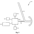
Fig. 2 is a block diagram of a brake pedal assembly of the brake-by-wire brake system ofFig. 1 ; and -
Fig. 3 is a block diagram of a brake pedal sensor of the brake-by-wire brake system ofFig. 1 . - In
Fig. 1 there is shown a brake-by-wire brake system, generally designated 10, according to one aspect of the disclosed distributed E/E architectures for brake-by-wire brake systems. Thesystem 10 may include a left-frontcorner brake module 12, a right-frontcorner brake module 14, a right-rearcorner brake module 16, a left-rearcorner brake module 18, apower distribution box 20, a supervisoryelectronic control unit 22, abrake switch 24, apark brake switch 25,brake pedal sensors brake lights - Each of the
corner brake modules braking device control electronics control electronics braking devices braking devices braking devices corner brake modules - The
power distribution box 20 may be a fault-tolerant power network and may distribute electrical power to the right-front module 14 andsensor 28 overline 54, to the right-rear module 16 overline 56, to the left-rear module 18 overline 60 and to the left-front module 12 andsensor 30 overline 62. The supervisoryelectronic control unit 22 may receive power from thepower distribution box 20 overline 58 or, alternatively, may be directly powered by the vehicle battery (not shown). Thepower distribution box 20 may include control electronics (e.g., an electronic control unit) and may selectively apply electrical power tolines system 10 that are malfunctioning, thereby allowing thesystem 10 to continue to operate despite one or more malfunctions in the system. - At this point, those skilled in the art will appreciate that
power distribution box 20 is an optional component and thesystem 10 may be powered using any available means. For example, the right-front module 14,sensor 28, right-rear module 16,vehicle dynamics module 22, left-rear module 18, left-front module 12 andsensor 30 may each be directly connected to one or more batteries (not shown) or other power sources. - The supervisory
electronic control unit 22 may compliment thecorner brake modules electronic control unit 22 may be a vehicle dynamics module, as is well known in the art. Optionally, the supervisoryelectronic control unit 22 may be connected to thebrake lights line 64 such that thebrake lights electronic control unit 22 performs certain high-level braking functions. - As shown in
Fig. 2 , thebrake switch 24 andbrake pedal sensors brake pedal assembly 66. Those skilled in the art will appreciate that two ormore brake switches 24 may be used without departing from the scope of the present disclosure. Thebrake pedal assembly 66 may include apedal feel emulator 68 and abrake pedal 70 connected to thepedal feel emulator 68 by amechanical connection 72. Thepedal feel emulator 68 may be a damper, a spring or the like adapted to provide resistance when a user depresses thebrake pedal 70, thereby emulating the feel of a traditional hydraulic brake system. - The
brake switch 24 may monitor movement of thebrake pedal 70 to detect whether a user has depressed the brake pedal. As shown inFig. 1 , signals from thebrake switch 24 may be directly communicated to the right-frontcorner brake module 14 overline 74 and left-frontcorner brake module 12 overline 76. However, those skilled in the art will appreciate that thebrake switch 24 may be in direct communication with any one or more of thecorner brake modules electronic control unit 22, thebrake switch 24 may be connected to thebrake lights line 64 such that thebrake lights Fig. 2 ) is manipulated. - When the
brake switch 24 is actuated, and regardless of other inputs to thesystem 10 or the lack thereof, thecorner brake modules brake switch 24 may automatically apply a certain predetermined amount of braking force. For example, actuation of thebrake switch 24 may initiate an automatic 20 percent brake apply. Furthermore, the automatic brake apply stemming from actuation of thebrake switch 24 may be communicated to the othercorner brake modules - Accordingly, in the event of a system failure, such as a failure of the communication bus (discussed below), the driver's intent to brake may be detected by the
brake switch 24 and directly communicated to at least onecorner brake module system 10 with a first redundant, fail-safe option. - The
park brake switch 25 may initiate a parking brake procedure, similar to a traditional parking brake, wherein one or more of thecorner brake modules Fig. 1 , signals from thepark brake switch 25 may be directly communicated to the right-frontcorner brake module 14 overline 29 and the left-frontcorner brake module 12 overline 27. However, those skilled in the art will appreciate that thepark brake switch 25 may be in direct communication with any one or more of thecorner brake modules park brake switches 25 may be used without departing from the scope of the present disclosure. - Therefore, when the
park brake switch 25 is actuated, and regardless of other inputs to thesystem 10 or the lack thereof, thecorner brake modules park brake switch 25 may automatically apply a certain predetermined amount of braking force or undergo a certain predetermined braking routine. For example, actuation of thepark brake switch 25 while traveling a 40 miles per hour may initiate a braking routing that arrives at 100 percent brake apply over 5 seconds. Furthermore, the automatic brake routine initiated in response to actuation of thepark brake switch 25 may be communicated to the othercorner brake modules - Accordingly, in the event of a system failure, such as a failure of the communication bus, the driver may actuate the
park brake switch 25 to initiate an emergency brake routine. The emergency brake routine may be performed by at least those corner brake modules that are directly connected to thepark brake switch 25, thereby providing thesystem 10 with a second redundant, fail-safe option. - The
system 10 may include threebrake pedal sensors brake pedal sensors system 10 for redundancy. However, those skilled in the art will appreciate that any number of brake pedal sensors may be used without departing from the scope of the present disclosure. These sensors may be with or without internal redundancy. In order to be single fault tolerant, minimum safety requirements may require at least three basic sensors (i.e., without internal redundancy), or two sensors with internal redundancy (i.e., two fail-safe sensors). Particularly, in the case where bothsensor 28 connected to the right-front brake module 14 andsensor 30 connected to the left-front corner module 12 present internal redundancy (i.e.,sensors third sensor 26 connected to the supervisoryelectronic control unit 22 may no longer be necessary. -
Brake pedal sensor 26 may be a force sensor, a pedal travel sensor or the like and may communicate sensor signals to the supervisoryelectronic control unit 22 by adirect connection 90, such as, for example, a single wire analog connection.Brake pedal sensors front 14 and left-front 12 corner brake modules. However, those skilled in the art will appreciate that alternative architectures may be employed without departing from the scope of the present disclosure. For example, modifiedsensors sensor 28 may be directly connected to the right-frontcorner brake module 14 andsensor 30 may be directly connected to the left-rear corner brake module 18) or in a four-corner arrangement. - The modified
brake pedal sensors Fig. 3 ,sensor 28, likesensor 30, may includesensor electronics 78 and astar coupler 80, each of which may be connected to a power source (line 54) and ground (line 55). Thesensor electronics 78 ofsensor 28 may be connected to the right-frontcorner brake module 14 by adirect connection 86, such as, for example, a single wire analog connection. - Thus, the
star coupler 80 insensor 28 may facilitate communication between the left-frontcorner brake module 12, the right-frontcorner brake module 14, the right-rearcorner brake module 16, the left-rearcorner brake module 18, thepower distribution box 20 and/or the supervisoryelectronic control unit 22 over a first channel (shown by solid ray lines 82) of a serial communication bus. Furthermore, as shown inFig. 1 ,sensor 30 may be a modified sensor incorporating an integral star coupler and may be connected to the left-frontcorner brake module 12 by adirect connection 88, such as, for example, a single wire analog connection. Therefore, the star coupler (not shown) ofsensor 30 may facilitate communication between the left-frontcorner brake module 12, the right-frontcorner brake module 14, the right-rearcorner brake module 16, the left-rearcorner brake module 18, thepower distribution box 20 and/or the supervisoryelectronic control unit 22 over a second channel (shown by broken ray lines 84) of the serial communication bus. - The serial communication bus may be any communication bus, such as a time-triggered communication bus with partial or complete channel redundancy. The two modified
sensors system 10 without departing from the scope of the present disclosure. Design considerations, including the quantity and placement of modified sensors, may be driven by the number of available communication bus channels and the desired amount of redundancy. - Accordingly, sensor signals from modified
sensor 28 may be directly communicated to the right-frontcorner brake module 14 byconnection 86. If necessary, the right-frontcorner brake module 14 may perform an analog-to-digital conversion of the sensor signals received from the modifiedsensor 28. From the right-frontcorner brake module 14, the sensor signals may then be communicated to the right-rearcorner brake module 16, the left-rearcorner brake module 18, the left-frontcorner brake module 12, thepower distribution box 20 and the supervisoryelectronic control unit 22, either over the first channel (solid ray lines 82) of the serial communication bus by way of thestar coupler 80 of modifiedsensor 28 and/or over the second channel (broken ray lines 84) of the serial communication bus by of the star coupler (not shown) of the modifiedsensor 30. - Furthermore, sensor signals from modified
sensor 30 may be directly communicated to the left-frontcorner brake module 12 byconnection 88. If necessary, the left-frontcorner brake module 12 may perform an analog-to-digital conversion of the sensor signals received from the modifiedsensor 30. From the left-frontcorner brake module 12, the sensor signals may then be communicated to the right-frontcorner brake module 14, the right-rearcorner brake module 16, the left-rearcorner brake module 18, thepower distribution box 20 and the supervisoryelectronic control unit 22, either over the first channel (solid ray lines 82) of the serial communication bus by way of thestar coupler 80 of the modifiedsensor 28 and/or over the second channel (broken ray lines 84) of the serial communication bus by way of the star coupler (not shown) of modifiedsensor 30. - Thus, modified
sensors system 10 and reduces costs by removing the complex, single pedal feel emulator electronic control unit and implementing a distributed E/E architecture using electronic control units already available in traditional brake-by-wire brake systems. - Furthermore, the
system 10 enhances several safety points. First, by spatially distributing the driver's intent function and its related electronics on the whole E/E architecture, the residual probability of an occurrence of a spatial proximity fault is reduced. Second, in case of a communication bus loss, one or more of the modified pedal sensors is able to communicate directly with the corner brake modules, thereby reducing the risk of accident. - Although various aspects of the disclosed distributed E/E architectures for brake-by-wire brake systems have been shown and described, modifications may occur to those skilled in the art upon reading the specification. The present application includes such modifications and is limited only by the scope of the claims.
Claims (14)
- A brake system comprising:a communication bus;a sensor including an integral star coupler, said star coupler being in communication with said communication bus, wherein said sensor generates a sensor signal;a first electronic control unit directly connected to said sensor to receive said sensor signal, said first electronic control unit being in communication with said communication bus; anda second electronic control unit in communication with said communication bus, wherein said second electronic control unit receives said sensor signal over said communication bus by way of said star coupler.
- The brake system of claim 1 further comprising a second sensor, said second sensor including an integral star coupler.
- The brake system according to anyone of claim 1 or 2 further comprising a brake pedal, wherein said sensor signal is generated in response to manipulation of said brake pedal.
- The brake system according to anyone of the preceding claims further comprising a brake switch in direct communication with at least one of said first and said second electronic control units.
- The brake system according to anyone of the preceding claims wherein said communication bus includes at least a first channel and a second channel; further comprising:a first brake pedal sensor including an integral star coupler, said star coupler being in communication with said communication bus by way of said first channel, wherein said first sensor generates a first sensor signal;a second brake pedal sensor including an integral star coupler, said star coupler being in communication with said communication bus by way of said second channel, wherein said second sensor generates a second sensor signal;wherein said first electronic control unit is directly connected to said first sensor to directly receive said first sensor signal, said first electronic control unit being in communication with said first and said second channels; andwherein said second electronic control unit is directly connected to said second sensor to directly received said second sensor signal, said second electronic control unit being in communication with said first and said second channels,wherein said first electronic control unit receives said second sensor signal over said first channel by way of said first star coupler and said second channel by way of said second star coupler and wherein said second electronic control unit receives said first sensor signal over said first channel by way of said first star coupler and said second channel by way of said second star coupler.
- The brake system according to anyone of the preceding claims, wherein said communication bus includes at least a first channel and a second channel; further comprising:a plurality of electronic control units, each electronic control unit of said plurality of electronic control units being in communication with said communication bus by way of at least one of said first channel and said second channel;at least one park brake switch in direct communication with at least one of said plurality of electronic control units;at least one brake switch in direct communication with at least one of said plurality of electronic control units;a plurality of sensors, at least one sensor of said plurality of sensors being in direct communication with at least one of said plurality of electronic control units,wherein said plurality of sensors, said at least one park brake switch and said at least one brake switch provide a set of redundant, fail-safe signals to said plurality of electronic control units.
- The brake system of claim 6 wherein a first one of said plurality of electronic control units is in communication with said communication bus by way of said first channel, a second one of said plurality of electronic control units is in communication with said communication bus by way of said second channel, and a third one of said plurality of electronic control units is in communication with said communication bus by way of said first channel and said second channel.
- The brake system of claim 6 or 7 wherein said first channel is implemented by a first star coupler and said second channel is implemented by a second star coupler, said first star coupler being integral with a first one of said plurality of sensors and said second star coupler being integral with a second one of said plurality of sensors.
- The brake system of claim 8 wherein said first one of said plurality of sensors includes associated conditioning electronics, and wherein said first star coupler is located in said conditioning electronics.
- The brake system according to anyone of claims 6 to 9 wherein said communication bus includes a plurality of segments, wherein a first one of said plurality of segments includes at least one of said plurality of electronic control units and a second one of said plurality of segments includes at least one of said plurality of electronic control units, and wherein at least one of said plurality of sensors is directly connected to at least one of said electronic control units of said first segment and at least one of said plurality of sensors is directly connected to at least one of said electronic control units of said second segment.
- The brake system of claim 10 wherein each of said plurality of electronic control units which receives a signal from at least one of said plurality of sensors is on an independent one of said plurality of segments of said communication bus.
- The brake system according to anyone of claims 6 to 11 wherein said communication bus includes a first segment and a second segment, said first segment including a front-right corner brake module and a rear-left corner brake module, said second segment including a front-left corner brake module and a rear-right corner brake module, wherein at least one of said plurality of sensors is directly connected to at least one of said corner brake modules of said first segment, and wherein at least one of said plurality of sensors is directly connected to at least one of said corner brake modules of said second segment.
- The brake system according to anyone of claims 6 to 12 wherein said communication bus includes a first segment and a second segment, said first segment including a front-right corner brake module and a front-left corner brake module, said second segment including a rear-right corner brake module and a rear-left corner brake module, wherein at least one of said plurality of sensors is directly connected to at least one of said corner brake modules of said first segment, and wherein at least one of said plurality of sensors is directly connected to at least one of said corner brake modules of said second segment.
- The brake system according to anyone of claims 6 to 13 wherein said at least one brake switch is in direct communication with a first one of said plurality of electronic control units which is in direct communication with a first one of said plurality of sensors, and said at least one park brake switch is in direct communication with a second one of said plurality of electronic control units which is in direct communication with a second one of said plurality of sensors.
Applications Claiming Priority (1)
| Application Number | Priority Date | Filing Date | Title |
|---|---|---|---|
| US12/011,662 US20090189441A1 (en) | 2008-01-29 | 2008-01-29 | Distributed electrical/electronic architectures for brake-by-wire brake systems |
Publications (2)
| Publication Number | Publication Date |
|---|---|
| EP2085276A1 true EP2085276A1 (en) | 2009-08-05 |
| EP2085276B1 EP2085276B1 (en) | 2015-05-27 |
Family
ID=40578253
Family Applications (1)
| Application Number | Title | Priority Date | Filing Date |
|---|---|---|---|
| EP09150960.4A Not-in-force EP2085276B1 (en) | 2008-01-29 | 2009-01-20 | Distributed electrical/electronic architectures for brake-by-wire brake systems |
Country Status (2)
| Country | Link |
|---|---|
| US (1) | US20090189441A1 (en) |
| EP (1) | EP2085276B1 (en) |
Families Citing this family (9)
| Publication number | Priority date | Publication date | Assignee | Title |
|---|---|---|---|---|
| CN101987578A (en) * | 2009-07-31 | 2011-03-23 | 北京京西重工有限公司 | Distributed electric/electronic structure with line control brake system |
| DE202010017317U1 (en) * | 2010-10-29 | 2011-10-27 | Küster Holding GmbH | Control device and actuator for the parking brake of a vehicle |
| WO2014138764A1 (en) * | 2013-03-14 | 2014-09-18 | Fts Computertechnik Gmbh | Method for limiting the risk of errors in a redundant, safety-related control system for a motor vehicle |
| US9061671B2 (en) | 2013-08-27 | 2015-06-23 | Bendix Commercial Vehicle Systems Llc | Driver braking demand indicator apparatus for a heavy vehicle |
| EP3741634B1 (en) * | 2019-05-23 | 2022-07-06 | Robert Bosch GmbH | Distributed electric park brake control |
| KR20200140751A (en) * | 2019-06-07 | 2020-12-16 | 주식회사 만도 | Ecu structure in brake system |
| DE102020213130A1 (en) * | 2019-10-22 | 2021-04-22 | Continental Teves Ag & Co. Ohg | Braking system for a motor vehicle |
| US11465636B2 (en) | 2021-02-01 | 2022-10-11 | Ree Automotive Ltd. | Control systems for vehicle corner modules and methods of operation |
| CN114701473A (en) * | 2021-12-27 | 2022-07-05 | 瀚德万安(上海)电控制动系统有限公司 | Communication system of electric control brake device |
Citations (5)
| Publication number | Priority date | Publication date | Assignee | Title |
|---|---|---|---|---|
| EP0832800A2 (en) * | 1996-09-28 | 1998-04-01 | WABCO GmbH | Electronic braking system for wheeled vehicles |
| WO1998036956A1 (en) * | 1997-02-19 | 1998-08-27 | Siemens Aktiengesellschaft | Braking system for a motor vehicle and method for transmitting data in an electrically controlled braking system for motor vehicles |
| EP0924125A2 (en) * | 1997-12-20 | 1999-06-23 | DaimlerChrysler AG | Vehicle brake equipement |
| DE19826131A1 (en) * | 1998-06-12 | 1999-12-16 | Bosch Gmbh Robert | Electrical braking system for a motor vehicle has optimised operating reliability and availability |
| US6345225B1 (en) * | 1997-11-22 | 2002-02-05 | Continental Teves Ag & Co., Ohg | Electromechanical brake system |
Family Cites Families (32)
| Publication number | Priority date | Publication date | Assignee | Title |
|---|---|---|---|---|
| US5001752A (en) * | 1989-10-13 | 1991-03-19 | Fischer Addison M | Public/key date-time notary facility |
| US5030824A (en) * | 1990-02-22 | 1991-07-09 | The Boeing Company | Optical position sensor employing encoder delay |
| US5022080A (en) * | 1990-04-16 | 1991-06-04 | Durst Robert T | Electronic notary |
| US5136647A (en) * | 1990-08-02 | 1992-08-04 | Bell Communications Research, Inc. | Method for secure time-stamping of digital documents |
| US5136646A (en) * | 1991-03-08 | 1992-08-04 | Bell Communications Research, Inc. | Digital document time-stamping with catenate certificate |
| FR2697910B1 (en) * | 1992-11-09 | 1995-01-13 | Onera (Off Nat Aerospatiale) | Device for measuring a physical quantity by time coding. |
| US5373561A (en) * | 1992-12-21 | 1994-12-13 | Bell Communications Research, Inc. | Method of extending the validity of a cryptographic certificate |
| US5422953A (en) * | 1993-05-05 | 1995-06-06 | Fischer; Addison M. | Personal date/time notary device |
| CN1149783C (en) * | 1994-10-28 | 2004-05-12 | 舒尔蒂,Com股份有限公司 | Digital document authentication system for providing certificate which authenticates and uniquely identifies document |
| US5937406A (en) * | 1997-01-31 | 1999-08-10 | Informix Software, Inc. | File system interface to a database |
| US6330549B1 (en) * | 1997-10-30 | 2001-12-11 | Xerox Corporation | Protected shareware |
| US6189096B1 (en) * | 1998-05-06 | 2001-02-13 | Kyberpass Corporation | User authentification using a virtual private key |
| US6393126B1 (en) * | 1999-06-23 | 2002-05-21 | Datum, Inc. | System and methods for generating trusted and authenticatable time stamps for electronic documents |
| CA2317139C (en) * | 1999-09-01 | 2006-08-08 | Nippon Telegraph And Telephone Corporation | Folder type time stamping system and distributed time stamping system |
| US6976165B1 (en) * | 1999-09-07 | 2005-12-13 | Emc Corporation | System and method for secure storage, transfer and retrieval of content addressable information |
| US6965998B1 (en) * | 1999-12-10 | 2005-11-15 | International Business Machines Corporation | Time stamping method using time-based signature key |
| US7412462B2 (en) * | 2000-02-18 | 2008-08-12 | Burnside Acquisition, Llc | Data repository and method for promoting network storage of data |
| GB2361331A (en) * | 2000-04-13 | 2001-10-17 | Int Computers Ltd | Electronic content storage |
| US6915433B1 (en) * | 2000-09-28 | 2005-07-05 | Sumisho Computer Systems Corporation | Securely extensible component meta-data |
| GB2376323B (en) * | 2001-06-09 | 2006-03-15 | Hewlett Packard Co | Trusted and verifiable data storage system |
| US6883068B2 (en) * | 2001-12-17 | 2005-04-19 | Sun Microsystems, Inc. | Methods and apparatus for implementing a chche replacement scheme |
| US7167986B2 (en) * | 2001-12-26 | 2007-01-23 | Storage Technology Corporation | Upgradeable timestamp mechanism |
| US20030126446A1 (en) * | 2001-12-27 | 2003-07-03 | Jacques Debiez | Method and system for providing a secure time reference in a worm environment |
| EP1523826B1 (en) * | 2002-07-18 | 2007-12-12 | VEGA Grieshaber KG | Bus station with an integrated bus monitor function |
| US20040024954A1 (en) * | 2002-07-30 | 2004-02-05 | Rust Robert A. | Time stamp management system for disk arrays |
| US20040054901A1 (en) * | 2002-09-17 | 2004-03-18 | Microsoft Corporation | Creating and verifying a sequence of consecutive data |
| US7263521B2 (en) * | 2002-12-10 | 2007-08-28 | Caringo, Inc. | Navigation of the content space of a document set |
| US7976109B2 (en) * | 2003-01-14 | 2011-07-12 | Bwi Company Limited S.A. | Failsafe operation of a hybrid brake system for a vehicle |
| US6984001B2 (en) * | 2003-09-29 | 2006-01-10 | Haldex Brake Products Ab | Power supply network for brake system |
| DE602006010123D1 (en) * | 2005-02-28 | 2009-12-17 | Delphi Tech Inc | Braking system with a fault-tolerant communication node architecture |
| DE102006052255A1 (en) * | 2006-11-03 | 2008-05-08 | Schott Ag | Passive star coupler i.e. pigtail module, for optical network i.e. bus system, of e.g. aircraft, has light reflector reflecting light into light conductor section i.e. core-shell-rod, such that light is transmitted through one conductor |
| US7850254B2 (en) * | 2007-02-20 | 2010-12-14 | Bwi Company Limited S.A. | Extreme emergency braking systems for brake-by-wire brake systems |
-
2008
- 2008-01-29 US US12/011,662 patent/US20090189441A1/en not_active Abandoned
-
2009
- 2009-01-20 EP EP09150960.4A patent/EP2085276B1/en not_active Not-in-force
Patent Citations (5)
| Publication number | Priority date | Publication date | Assignee | Title |
|---|---|---|---|---|
| EP0832800A2 (en) * | 1996-09-28 | 1998-04-01 | WABCO GmbH | Electronic braking system for wheeled vehicles |
| WO1998036956A1 (en) * | 1997-02-19 | 1998-08-27 | Siemens Aktiengesellschaft | Braking system for a motor vehicle and method for transmitting data in an electrically controlled braking system for motor vehicles |
| US6345225B1 (en) * | 1997-11-22 | 2002-02-05 | Continental Teves Ag & Co., Ohg | Electromechanical brake system |
| EP0924125A2 (en) * | 1997-12-20 | 1999-06-23 | DaimlerChrysler AG | Vehicle brake equipement |
| DE19826131A1 (en) * | 1998-06-12 | 1999-12-16 | Bosch Gmbh Robert | Electrical braking system for a motor vehicle has optimised operating reliability and availability |
Also Published As
| Publication number | Publication date |
|---|---|
| EP2085276B1 (en) | 2015-05-27 |
| US20090189441A1 (en) | 2009-07-30 |
Similar Documents
| Publication | Publication Date | Title |
|---|---|---|
| EP2085276B1 (en) | Distributed electrical/electronic architectures for brake-by-wire brake systems | |
| US11124169B2 (en) | System comprising separate control units for the actuation units of an electric parking brake | |
| US8645003B2 (en) | Braking control system and method for vehicle | |
| CN109843673B (en) | Motor vehicle system, control method, storage medium, and control apparatus system | |
| US5961190A (en) | Brake system for a motor vehicle | |
| KR102481911B1 (en) | Motor vehicle control unit for electric parking brake | |
| US6345225B1 (en) | Electromechanical brake system | |
| US6317675B1 (en) | Electromechanical brake system | |
| CN101687498B (en) | Combined braking system, particularly for motor vehicles | |
| EP3000674B1 (en) | Electronic brake support system for use when service brake system has failed or is degraded | |
| JP5254334B2 (en) | Brake device for vehicle and method for operating vehicle brake device | |
| US9205818B2 (en) | Brake system and method for controlling a vehicle brake | |
| EP3626562B1 (en) | Brake system for a vehicle, vehicle and method of controlling a brake system for a vehicle | |
| US20080021623A1 (en) | Redundant Brake Control System for a Vehicle | |
| EP3626557B1 (en) | Brake system for a vehicle | |
| KR20130133191A (en) | Fault-secure parking brake for motor vehicles | |
| US20030006726A1 (en) | Electrical brake system | |
| JPH11263212A (en) | Brake system for vehicle | |
| JP2020523255A (en) | Brake calipers for vehicles with a braking control unit | |
| US20210339723A1 (en) | Vehicle Control Apparatus and Vehicle Control System | |
| EP3626559B1 (en) | Brake system for a vehicle | |
| CN115230654A (en) | Brake system for vehicle | |
| GB2443921A (en) | Fail-safe hydraulic braking system | |
| CN108495773B (en) | Method and device for operating a brake system of a vehicle, and brake system | |
| CN112739590B (en) | Redundant braking system for autonomous vehicles |
Legal Events
| Date | Code | Title | Description |
|---|---|---|---|
| PUAI | Public reference made under article 153(3) epc to a published international application that has entered the european phase |
Free format text: ORIGINAL CODE: 0009012 |
|
| AK | Designated contracting states |
Kind code of ref document: A1 Designated state(s): AT BE BG CH CY CZ DE DK EE ES FI FR GB GR HR HU IE IS IT LI LT LU LV MC MK MT NL NO PL PT RO SE SI SK TR |
|
| AX | Request for extension of the european patent |
Extension state: AL BA RS |
|
| 17P | Request for examination filed |
Effective date: 20100205 |
|
| 17Q | First examination report despatched |
Effective date: 20100301 |
|
| AKX | Designation fees paid |
Designated state(s): AT BE BG CH CY CZ DE DK EE ES FI FR GB GR HR HU IE IS IT LI LT LU LV MC MK MT NL NO PL PT RO SE SI SK TR |
|
| RAP1 | Party data changed (applicant data changed or rights of an application transferred) |
Owner name: BWI COMPANY LIMITED S.A. |
|
| GRAP | Despatch of communication of intention to grant a patent |
Free format text: ORIGINAL CODE: EPIDOSNIGR1 |
|
| INTG | Intention to grant announced |
Effective date: 20141215 |
|
| RIN1 | Information on inventor provided before grant (corrected) |
Inventor name: DEGOUL, PAUL Inventor name: DISSER, ROBERT J. |
|
| GRAS | Grant fee paid |
Free format text: ORIGINAL CODE: EPIDOSNIGR3 |
|
| GRAA | (expected) grant |
Free format text: ORIGINAL CODE: 0009210 |
|
| AK | Designated contracting states |
Kind code of ref document: B1 Designated state(s): AT BE BG CH CY CZ DE DK EE ES FI FR GB GR HR HU IE IS IT LI LT LU LV MC MK MT NL NO PL PT RO SE SI SK TR |
|
| REG | Reference to a national code |
Ref country code: GB Ref legal event code: FG4D |
|
| REG | Reference to a national code |
Ref country code: CH Ref legal event code: EP |
|
| REG | Reference to a national code |
Ref country code: AT Ref legal event code: REF Ref document number: 728666 Country of ref document: AT Kind code of ref document: T Effective date: 20150615 |
|
| REG | Reference to a national code |
Ref country code: IE Ref legal event code: FG4D |
|
| REG | Reference to a national code |
Ref country code: DE Ref legal event code: R096 Ref document number: 602009031398 Country of ref document: DE |
|
| REG | Reference to a national code |
Ref country code: AT Ref legal event code: MK05 Ref document number: 728666 Country of ref document: AT Kind code of ref document: T Effective date: 20150527 |
|
| REG | Reference to a national code |
Ref country code: LT Ref legal event code: MG4D |
|
| PG25 | Lapsed in a contracting state [announced via postgrant information from national office to epo] |
Ref country code: FI Free format text: LAPSE BECAUSE OF FAILURE TO SUBMIT A TRANSLATION OF THE DESCRIPTION OR TO PAY THE FEE WITHIN THE PRESCRIBED TIME-LIMIT Effective date: 20150527 Ref country code: NO Free format text: LAPSE BECAUSE OF FAILURE TO SUBMIT A TRANSLATION OF THE DESCRIPTION OR TO PAY THE FEE WITHIN THE PRESCRIBED TIME-LIMIT Effective date: 20150827 Ref country code: LT Free format text: LAPSE BECAUSE OF FAILURE TO SUBMIT A TRANSLATION OF THE DESCRIPTION OR TO PAY THE FEE WITHIN THE PRESCRIBED TIME-LIMIT Effective date: 20150527 Ref country code: HR Free format text: LAPSE BECAUSE OF FAILURE TO SUBMIT A TRANSLATION OF THE DESCRIPTION OR TO PAY THE FEE WITHIN THE PRESCRIBED TIME-LIMIT Effective date: 20150527 Ref country code: PT Free format text: LAPSE BECAUSE OF FAILURE TO SUBMIT A TRANSLATION OF THE DESCRIPTION OR TO PAY THE FEE WITHIN THE PRESCRIBED TIME-LIMIT Effective date: 20150928 Ref country code: ES Free format text: LAPSE BECAUSE OF FAILURE TO SUBMIT A TRANSLATION OF THE DESCRIPTION OR TO PAY THE FEE WITHIN THE PRESCRIBED TIME-LIMIT Effective date: 20150527 |
|
| REG | Reference to a national code |
Ref country code: NL Ref legal event code: MP Effective date: 20150527 |
|
| PG25 | Lapsed in a contracting state [announced via postgrant information from national office to epo] |
Ref country code: LV Free format text: LAPSE BECAUSE OF FAILURE TO SUBMIT A TRANSLATION OF THE DESCRIPTION OR TO PAY THE FEE WITHIN THE PRESCRIBED TIME-LIMIT Effective date: 20150527 Ref country code: AT Free format text: LAPSE BECAUSE OF FAILURE TO SUBMIT A TRANSLATION OF THE DESCRIPTION OR TO PAY THE FEE WITHIN THE PRESCRIBED TIME-LIMIT Effective date: 20150527 Ref country code: GR Free format text: LAPSE BECAUSE OF FAILURE TO SUBMIT A TRANSLATION OF THE DESCRIPTION OR TO PAY THE FEE WITHIN THE PRESCRIBED TIME-LIMIT Effective date: 20150828 Ref country code: BG Free format text: LAPSE BECAUSE OF FAILURE TO SUBMIT A TRANSLATION OF THE DESCRIPTION OR TO PAY THE FEE WITHIN THE PRESCRIBED TIME-LIMIT Effective date: 20150827 Ref country code: IS Free format text: LAPSE BECAUSE OF FAILURE TO SUBMIT A TRANSLATION OF THE DESCRIPTION OR TO PAY THE FEE WITHIN THE PRESCRIBED TIME-LIMIT Effective date: 20150927 |
|
| REG | Reference to a national code |
Ref country code: FR Ref legal event code: PLFP Year of fee payment: 8 |
|
| PG25 | Lapsed in a contracting state [announced via postgrant information from national office to epo] |
Ref country code: EE Free format text: LAPSE BECAUSE OF FAILURE TO SUBMIT A TRANSLATION OF THE DESCRIPTION OR TO PAY THE FEE WITHIN THE PRESCRIBED TIME-LIMIT Effective date: 20150527 Ref country code: DK Free format text: LAPSE BECAUSE OF FAILURE TO SUBMIT A TRANSLATION OF THE DESCRIPTION OR TO PAY THE FEE WITHIN THE PRESCRIBED TIME-LIMIT Effective date: 20150527 |
|
| PG25 | Lapsed in a contracting state [announced via postgrant information from national office to epo] |
Ref country code: RO Free format text: LAPSE BECAUSE OF NON-PAYMENT OF DUE FEES Effective date: 20150527 Ref country code: PL Free format text: LAPSE BECAUSE OF FAILURE TO SUBMIT A TRANSLATION OF THE DESCRIPTION OR TO PAY THE FEE WITHIN THE PRESCRIBED TIME-LIMIT Effective date: 20150527 Ref country code: SK Free format text: LAPSE BECAUSE OF FAILURE TO SUBMIT A TRANSLATION OF THE DESCRIPTION OR TO PAY THE FEE WITHIN THE PRESCRIBED TIME-LIMIT Effective date: 20150527 Ref country code: CZ Free format text: LAPSE BECAUSE OF FAILURE TO SUBMIT A TRANSLATION OF THE DESCRIPTION OR TO PAY THE FEE WITHIN THE PRESCRIBED TIME-LIMIT Effective date: 20150527 |
|
| PGFP | Annual fee paid to national office [announced via postgrant information from national office to epo] |
Ref country code: MC Payment date: 20151209 Year of fee payment: 8 |
|
| REG | Reference to a national code |
Ref country code: DE Ref legal event code: R097 Ref document number: 602009031398 Country of ref document: DE |
|
| PGFP | Annual fee paid to national office [announced via postgrant information from national office to epo] |
Ref country code: NL Payment date: 20160111 Year of fee payment: 8 Ref country code: LU Payment date: 20160115 Year of fee payment: 8 |
|
| PLBE | No opposition filed within time limit |
Free format text: ORIGINAL CODE: 0009261 |
|
| STAA | Information on the status of an ep patent application or granted ep patent |
Free format text: STATUS: NO OPPOSITION FILED WITHIN TIME LIMIT |
|
| PG25 | Lapsed in a contracting state [announced via postgrant information from national office to epo] |
Ref country code: IT Free format text: LAPSE BECAUSE OF FAILURE TO SUBMIT A TRANSLATION OF THE DESCRIPTION OR TO PAY THE FEE WITHIN THE PRESCRIBED TIME-LIMIT Effective date: 20150527 |
|
| PGFP | Annual fee paid to national office [announced via postgrant information from national office to epo] |
Ref country code: CH Payment date: 20160111 Year of fee payment: 8 Ref country code: DE Payment date: 20160112 Year of fee payment: 8 Ref country code: IE Payment date: 20160112 Year of fee payment: 8 |
|
| 26N | No opposition filed |
Effective date: 20160301 |
|
| PG25 | Lapsed in a contracting state [announced via postgrant information from national office to epo] |
Ref country code: SI Free format text: LAPSE BECAUSE OF FAILURE TO SUBMIT A TRANSLATION OF THE DESCRIPTION OR TO PAY THE FEE WITHIN THE PRESCRIBED TIME-LIMIT Effective date: 20150527 |
|
| PGFP | Annual fee paid to national office [announced via postgrant information from national office to epo] |
Ref country code: BE Payment date: 20151223 Year of fee payment: 8 Ref country code: GB Payment date: 20160120 Year of fee payment: 8 |
|
| PG25 | Lapsed in a contracting state [announced via postgrant information from national office to epo] |
Ref country code: BE Free format text: LAPSE BECAUSE OF FAILURE TO SUBMIT A TRANSLATION OF THE DESCRIPTION OR TO PAY THE FEE WITHIN THE PRESCRIBED TIME-LIMIT Effective date: 20150527 |
|
| REG | Reference to a national code |
Ref country code: FR Ref legal event code: PLFP Year of fee payment: 9 |
|
| PG25 | Lapsed in a contracting state [announced via postgrant information from national office to epo] |
Ref country code: SE Free format text: LAPSE BECAUSE OF FAILURE TO SUBMIT A TRANSLATION OF THE DESCRIPTION OR TO PAY THE FEE WITHIN THE PRESCRIBED TIME-LIMIT Effective date: 20150527 Ref country code: NL Free format text: LAPSE BECAUSE OF FAILURE TO SUBMIT A TRANSLATION OF THE DESCRIPTION OR TO PAY THE FEE WITHIN THE PRESCRIBED TIME-LIMIT Effective date: 20150527 |
|
| REG | Reference to a national code |
Ref country code: DE Ref legal event code: R119 Ref document number: 602009031398 Country of ref document: DE |
|
| PGFP | Annual fee paid to national office [announced via postgrant information from national office to epo] |
Ref country code: MT Payment date: 20160119 Year of fee payment: 8 |
|
| REG | Reference to a national code |
Ref country code: CH Ref legal event code: PL |
|
| GBPC | Gb: european patent ceased through non-payment of renewal fee |
Effective date: 20170120 |
|
| PG25 | Lapsed in a contracting state [announced via postgrant information from national office to epo] |
Ref country code: MC Free format text: LAPSE BECAUSE OF NON-PAYMENT OF DUE FEES Effective date: 20170131 |
|
| PG25 | Lapsed in a contracting state [announced via postgrant information from national office to epo] |
Ref country code: CH Free format text: LAPSE BECAUSE OF NON-PAYMENT OF DUE FEES Effective date: 20170131 Ref country code: LI Free format text: LAPSE BECAUSE OF NON-PAYMENT OF DUE FEES Effective date: 20170131 |
|
| REG | Reference to a national code |
Ref country code: IE Ref legal event code: MM4A |
|
| PG25 | Lapsed in a contracting state [announced via postgrant information from national office to epo] |
Ref country code: LU Free format text: LAPSE BECAUSE OF NON-PAYMENT OF DUE FEES Effective date: 20170120 Ref country code: DE Free format text: LAPSE BECAUSE OF NON-PAYMENT OF DUE FEES Effective date: 20170801 Ref country code: GB Free format text: LAPSE BECAUSE OF NON-PAYMENT OF DUE FEES Effective date: 20170120 |
|
| REG | Reference to a national code |
Ref country code: FR Ref legal event code: PLFP Year of fee payment: 10 |
|
| PGFP | Annual fee paid to national office [announced via postgrant information from national office to epo] |
Ref country code: FR Payment date: 20171211 Year of fee payment: 10 |
|
| PG25 | Lapsed in a contracting state [announced via postgrant information from national office to epo] |
Ref country code: IE Free format text: LAPSE BECAUSE OF NON-PAYMENT OF DUE FEES Effective date: 20170120 |
|
| PG25 | Lapsed in a contracting state [announced via postgrant information from national office to epo] |
Ref country code: CY Free format text: LAPSE BECAUSE OF FAILURE TO SUBMIT A TRANSLATION OF THE DESCRIPTION OR TO PAY THE FEE WITHIN THE PRESCRIBED TIME-LIMIT Effective date: 20150527 Ref country code: HU Free format text: LAPSE BECAUSE OF FAILURE TO SUBMIT A TRANSLATION OF THE DESCRIPTION OR TO PAY THE FEE WITHIN THE PRESCRIBED TIME-LIMIT; INVALID AB INITIO Effective date: 20090120 |
|
| PG25 | Lapsed in a contracting state [announced via postgrant information from national office to epo] |
Ref country code: TR Free format text: LAPSE BECAUSE OF FAILURE TO SUBMIT A TRANSLATION OF THE DESCRIPTION OR TO PAY THE FEE WITHIN THE PRESCRIBED TIME-LIMIT Effective date: 20150527 Ref country code: MK Free format text: LAPSE BECAUSE OF FAILURE TO SUBMIT A TRANSLATION OF THE DESCRIPTION OR TO PAY THE FEE WITHIN THE PRESCRIBED TIME-LIMIT Effective date: 20150527 |
|
| PG25 | Lapsed in a contracting state [announced via postgrant information from national office to epo] |
Ref country code: MT Free format text: LAPSE BECAUSE OF NON-PAYMENT OF DUE FEES Effective date: 20170120 |
|
| PG25 | Lapsed in a contracting state [announced via postgrant information from national office to epo] |
Ref country code: FR Free format text: LAPSE BECAUSE OF NON-PAYMENT OF DUE FEES Effective date: 20190131 |