EP2084586B1 - Harmonic disturbance regulator - Google Patents
Harmonic disturbance regulator Download PDFInfo
- Publication number
- EP2084586B1 EP2084586B1 EP07844485.8A EP07844485A EP2084586B1 EP 2084586 B1 EP2084586 B1 EP 2084586B1 EP 07844485 A EP07844485 A EP 07844485A EP 2084586 B1 EP2084586 B1 EP 2084586B1
- Authority
- EP
- European Patent Office
- Prior art keywords
- harmonic
- signal
- feedback signal
- harmonics
- reference frame
- Prior art date
- Legal status (The legal status is an assumption and is not a legal conclusion. Google has not performed a legal analysis and makes no representation as to the accuracy of the status listed.)
- Active
Links
Images





Classifications
-
- G—PHYSICS
- G05—CONTROLLING; REGULATING
- G05B—CONTROL OR REGULATING SYSTEMS IN GENERAL; FUNCTIONAL ELEMENTS OF SUCH SYSTEMS; MONITORING OR TESTING ARRANGEMENTS FOR SUCH SYSTEMS OR ELEMENTS
- G05B13/00—Adaptive control systems, i.e. systems automatically adjusting themselves to have a performance which is optimum according to some preassigned criterion
- G05B13/02—Adaptive control systems, i.e. systems automatically adjusting themselves to have a performance which is optimum according to some preassigned criterion electric
-
- H—ELECTRICITY
- H02—GENERATION; CONVERSION OR DISTRIBUTION OF ELECTRIC POWER
- H02M—APPARATUS FOR CONVERSION BETWEEN AC AND AC, BETWEEN AC AND DC, OR BETWEEN DC AND DC, AND FOR USE WITH MAINS OR SIMILAR POWER SUPPLY SYSTEMS; CONVERSION OF DC OR AC INPUT POWER INTO SURGE OUTPUT POWER; CONTROL OR REGULATION THEREOF
- H02M1/00—Details of apparatus for conversion
- H02M1/12—Arrangements for reducing harmonics from AC input or output
-
- G—PHYSICS
- G05—CONTROLLING; REGULATING
- G05B—CONTROL OR REGULATING SYSTEMS IN GENERAL; FUNCTIONAL ELEMENTS OF SUCH SYSTEMS; MONITORING OR TESTING ARRANGEMENTS FOR SUCH SYSTEMS OR ELEMENTS
- G05B5/00—Anti-hunting arrangements
- G05B5/01—Anti-hunting arrangements electric
-
- H—ELECTRICITY
- H02—GENERATION; CONVERSION OR DISTRIBUTION OF ELECTRIC POWER
- H02P—CONTROL OR REGULATION OF ELECTRIC MOTORS, ELECTRIC GENERATORS OR DYNAMO-ELECTRIC CONVERTERS; CONTROLLING TRANSFORMERS, REACTORS OR CHOKE COILS
- H02P21/00—Arrangements or methods for the control of electric machines by vector control, e.g. by control of field orientation
- H02P21/22—Current control, e.g. using a current control loop
-
- H—ELECTRICITY
- H02—GENERATION; CONVERSION OR DISTRIBUTION OF ELECTRIC POWER
- H02P—CONTROL OR REGULATION OF ELECTRIC MOTORS, ELECTRIC GENERATORS OR DYNAMO-ELECTRIC CONVERTERS; CONTROLLING TRANSFORMERS, REACTORS OR CHOKE COILS
- H02P29/00—Arrangements for regulating or controlling electric motors, appropriate for both AC and DC motors
- H02P29/50—Reduction of harmonics
Definitions
- a repetitive controller Another technique is referred to in literature as a repetitive controller.
- This technique has several drawbacks.
- One drawback is that it does not learn or compensate for the phase of each harmonic of interest.
- the repetitive controller has infinite gain (i.e., integral action) at every multiple of the harmonic of interest and "learns" the magnitude. The same amplitude of correction is applied to the harmonic of interest and each of its multiples. In an actual system, each multiple of a harmonic may require a different amplitude for its compensation.
- the compensation for harmonic multiples not of interest must be removed.
- One method is by performing a Fast Fourier Transform (FFT), removing the bins containing the multiples not of interest and performing an inverse FFT, which is a cumbersome process. Additionally, the repetitive controller in many instances becomes unstable, which results in online learning of harmonics being precluded.
- FFT Fast Fourier Transform
- harmonic regulation is one where the harmonic torque disturbance is deliberately introduced to the system.
- Such applications include, for example, test stands where the electric motor must simulate the torque pulsations inherent in an internal combustion engine for the purpose of testing transmissions, alternators, air conditioners, pumps and other equipment.
- the usual method has been to use a torque profile which is mapped to the position of the simulated engine crank. This method has the disadvantage of not having good control at higher frequencies as a result of the limited bandwidth of the basic control algorithm.
- EP1467478 (Nissan Motor) discloses a motor control apparatus having a fundamental wave current control circuit that implements feedback control on a fundamental wave component of a motor current in a dq coordinate system rotating in synchronisation with the rotation of the motor and a higher harmonic current control circuit that implements feedback control on a higher harmonic component of the motor current in a dhqh coordinate system rotating with a frequency which is an integral multiple of the frequency of the fundamental wave component of the motor current, elements the higher harmonic component of the motor current from the control deviation between a fundamental wave current command value and a motor current feedback value.
- US5994867 discloses a method and a device for controlling a sensualist, field-oriented asynchronous machine, wherein a manipulated variable space vector and a stator frequency are calculated, by means of a two-component current control system, from which control signals are generated using a space vector modulation process.
- a PI controller of an EMF control system from the d-component of a calculated EMR space vector of the field-oriented control system is deactivated and its output signals set to zero at a stator frequency, determined as a function of a calculated de-component of a calculated EMF space vector and a calculated stator frequency that is less than or equal to a first limit frequency.
- the method may be used for speed control of a sensualist, filed-oriented asynchronous machine.
- Described herein is, among other things, a harmonic disturbance regulator, which was conceived to minimize and/or eliminate the mentioned problems.
- the harmonic regulator regulates to commanded values, including zero, a plurality of individual harmonics in a system having and/or requiring periodic disturbances.
- a feedback signal representing the harmonic being regulated is transformed from a source reference frame to a harmonic reference frame of the harmonic being regulated to form a qd feedback signal.
- the qd feedback signal is subtracted from the commanded value for the harmonic to form a qd error signal and is regulated.
- the regulated qd signal is transformed to a destination reference frame to form a compensation signal and the compensation signal is added to a control signal to form a qd control signal that drives each harmonic being regulated towards its commanded value.
- the angle used to transform the feedback signal to the harmonic reference frame is derived by multiplying the phase of the feedback signal in the source frame by the harmonic number of the harmonic being regulated and setting the harmonic angle to the modulo 2 ⁇ value of the resulting value.
- the angle used to transform the regulated signal to the destination reference frame is derived from the modulo 2 ⁇ of the phase of the feedback signal multiplied by the harmonic number subtracted by a difference value equal to destination harmonic number minus the source harmonic number.
- the system has an engine that is rotated over a speed range and when the engine speed goes below a predetermined value, the PI regulator used to regulate the qd signal is latched by zeroing the error signal, thereby keeping and the q and d values of the qd signal at the values that they were at prior to the engine speed going below the predetermined value.
- the harmonic regulator described herein regulates or eliminates harmonics that cause periodic torque disturbances.
- FIG. 1 an exemplary system 100 in which the present technology may operate is shown.
- the system includes a drive/controller 102 that receives three phase power at its input, converts it to a dc link, and controls motor 104 via power electronic switches (not shown).
- the motor 104 drives engine 106 through coupling 108.
- the engine exerts a periodic torque disturbance on the motor shaft 110 due to cylinder compression/cam linkage interaction during rotation of the engine 106.
- the drive/controller 102 can be of any form.
- the drive/controller 102 typically includes some form of computer readable media.
- Computer readable media can be any available media that can be accessed by the drive/controller 102 and can include both volatile and nonvolatile media, removable and non-removable media.
- the drive/controller 102 shall be in the form of a qd type of controller where the main control loops are used in the qd reference frame, also known as the dq reference frame.
- the main control loop block 200 receives inputs such as commanded speed, motor speed, motor acceleration, etc.
- the uvw control signal contains a quadrature axis control signal and a direct axis control signal.
- the qds control signal is transformed into an uvw control signal by qds to uvw block 202.
- the uvw control signal contains a control signals for each phase in the motor, which typically has three phases 120 degrees apart with respect to each other.
- the uvw control signal is used by uvw control block 204 to drive motor 104.
- the uvw control block 204 consists of an inverter that supplies power to each motor phase via pulse-width modulation (PWM) and/or the like.
- PWM pulse-width modulation
- the harmonic regulator 206 regulates one or more selected harmonics to specified values, which can be zero, by outputting a control signal that is added to the qds control signal when switch 208 is activated. While switch 208 is shown, in one embodiment the harmonic regulator 206 is directly connected to summer 210.
- the harmonic regulator 206 contains a plurality of individual harmonic regulators 300 n (see FIG. 3 ).
- the harmonic regulator 206 has an fqds input, an x input, and a dn input that are common to the plurality of individual harmonic regulators.
- the fqds input receives the vector feedback variable that is used in the main control loop and that has harmonic components due to the periodic torque disturbance.
- the fqds input could be motor acceleration, having, in the source frame, q axis magnitude only, or in an application for electrical voltage disturbance rejection (e.g., removing frequency dependent current harmonics due to inverter deadtime distortion), current feedback, potentially having both q and d axis magnitudes in the stationary reference frame.
- the x input is the angular position estimate of the fqds input upon which the harmonics are based and it sets the fundamental reference frame for the harmonics.
- the dn input is used as a "destination minus source" harmonic difference number for the output.
- a dn set to 1 when the source is the stationary frame sets the output to be in the first harmonic reference frame (i.e., synchronous fundamental reference frame) while a dn set to 0 sets the output to be in the stationary reference frame.
- the remaining multiple harmonic regulator inputs h 1 through h n and fqdcmd 1 through fqdcmd n are the harmonic numbers being regulated and the qd vector magnitude to which the harmonics are being controlled, respectively.
- a value of zero for the magnitude of these vectors causes the controller to regulate the associated harmonics to zero.
- the harmonics h 1 through h n to be regulated may be determined by an understanding of the nature of the system being controlled or by analyzing the disturbance using a Fast Fourier Transform or by other experimental methods.
- each of the individual harmonic regulators are summed at summing block 302 ( FIG. 3 ) and the summed output, fqddncomp, is summed with the qds control signal at summer 210.
- the fqds signal has only q axis magnitude, only the q axis component of the output is summed and the d axis component is held to zero.
- the x input and harmonic number h being regulated are multiplied (block 400) and the modulo 2 ⁇ is derived (block 402) to obtain the angle ⁇ (theta) at which the harmonic being regulated is with respect to the stationary reference frame (step 700).
- the angle ⁇ is used to derive the sine and cosine functions (block 404) used in the source to harmonic frame transformation block 406 (see FIG. 5 ) to transform the fqds vector feedback variables into the harmonic frame of harmonic number h (step 702).
- the fqds feedback variable would be transformed into the harmonic frame of the fifth harmonic.
- the resulting qdh variables are low pass filtered via filter block 408 to reduce or eliminate other frequencies present in the qdh variables so that the harmonic regulator 300 primarily regulates the harmonic of interest (step 704).
- bandpass filters could be implemented in the source reference frame prior to transformation to the harmonic reference frame.
- the resulting filtered qdh values are subtracted from the commanded qd values at summer 410 (step 706).
- the resulting error is regulated with a qd PI regulator (block 412) (step 708) and transformed (block 414 - see FIG.
- the sine and cosine functions used in block 414 are derived from block 416, which has an input angle derived from the modulo 2 ⁇ (block 418) of the x input multiplied (at block 420) by the harmonic number minus the dn input value.
- the fqddncomp value for the selected harmonic is summed with other values, if any, at summing block 302 ( FIG. 3 ), resulting in the fqddncomp output value of harmonic regulator 206.
- harmonics can be difficult to discern due to the "crowding" of harmonics due to the low fundamental frequency of the system at low speed.
- the PI block is latched and the qd values are kept to their values that were at or above the predetermined speed (step 712 - see FIG. 8 ). Tests have shown that regulating the harmonics with the latched value is better than if the harmonic disturbance regulator is completely disabled.
- FIGS. 9a-12e a simulated example of regulating two harmonics is shown.
- FIGS. 10a-10e and FIGS. 12a-12e are expanded views of the waveforms of FIGS 9a-9e and 11a-11e respectively.
- FIGS. 9a and 11a are the qd acceleration feedback signals that are quantized similar to how the signals would be when an incremental encoder is used and
- FIGS. 10a and 12a are expanded views of FIGS. 9a and 11a , respectively.
- FIGS. 9b and 11b are the transformed qd acceleration signals after being transformed into the harmonic reference frame of harmonic h1 and h2, respectively.
- FIGS. 10b and 12b are expanded views of FIGS. 9b and 11b , respectively.
- FIGS. 9c and 11c are the filtered and transformed qd acceleration signals. It can be seen how the filtered terms for both harmonics (i.e., the acceleration errors in this example) are forced to zero by the PI regulator outputs.
- FIGS. 10c and 12c are expanded views of FIGS. 9c and 11c , respectively.
- FIGS. 9d and 11d are the filtered and transformed qd acceleration signals after PI regulated.
- FIGS. 10d and 12d are expanded views of FIGS. 9d and 11d , respectively. It can be seen how each PI regulator output in the harmonic frame corresponds to a different magnitude and phase for each harmonic.
- FIGS. 9e and 11e are the PI regulated qd acceleration signals after being transformed back into the reference frame of FIGS. 9a and 11a .
- FIGS. 10e and 12e are expanded views of FIGS. 9e and 11e , respectively.
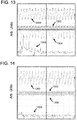
- Waveform 1300 is the electrical torque estimate
- waveform 1302 is the qds control signal ( FIG. 2 )
- waveform 1304 is the motor velocity
- waveform 1306 is a FFT of motor velocity.
- FIG. 13 illustrates the waveforms with the harmonic disturbance regulator disabled. Large peak values at several harmonics can clearly be seen in the FFT of the velocity.
- the harmonic disturbance regulator is enabled with the regulation setpoint set to a value of zero for the 2 nd , 4 th , 6 th , 8 th , 12 th and 16 th harmonics, it can be seen in FIG. 14 that the regulated harmonics have been decoupled in the system and that the motor velocity has little, if any, ripple. As a result, the periodic torque disturbance effects have been reduced and/or eliminated.
- FIGS. 15 and 16 provide an example of regulating harmonics in the same engine system operating at 600 rpm.
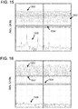
- Waveform 1500 is the electrical torque estimate
- waveform 1502 is the qds control signal ( FIG. 2 )
- waveform 1504 is the motor velocity
- waveform 1506 is a FFT of motor velocity.
- FIG. 15 illustrates the waveforms with the harmonic disturbance regulator disabled. Large peak values at several harmonics can clearly be seen in the FFT of the velocity.
- the harmonic disturbance regulator is enabled with the regulation setpoint set to a value of zero for the 2 nd , 4 th , 8 th and 12 th harmonics being regulated, it can be seen in FIG. 16 that the regulated harmonics have been decoupled in the system and that the motor velocity has little, if any, ripple. As a result, the periodic torque disturbance effects have been reduced and/or eliminated.
Landscapes
- Engineering & Computer Science (AREA)
- Power Engineering (AREA)
- Physics & Mathematics (AREA)
- Automation & Control Theory (AREA)
- General Physics & Mathematics (AREA)
- Artificial Intelligence (AREA)
- Medical Informatics (AREA)
- Software Systems (AREA)
- Evolutionary Computation (AREA)
- Computer Vision & Pattern Recognition (AREA)
- Health & Medical Sciences (AREA)
- Control Of Electric Motors In General (AREA)
- Control Of Ac Motors In General (AREA)
- Supply And Distribution Of Alternating Current (AREA)
Description
- There are many fields where operating a motor at a desired speed with little or no speed variation due to torque disturbance is required. For example, engine characterization requires operation at a selected speed. In a cold engine test system, an electronic motor drive is used to rotate an engine under test at a desired speed for purposes of, for example, engine design optimization, engine cylinder leakage characterization, etc. However, the engine under test exerts undesirable periodic torque disturbances on the motor shaft due to the engine cylinder compression/cam linkage interaction. The periodic torque disturbances are harmonically related to the rotational speed of the engine cam shaft and crank shaft and cause the actual engine speed to vary, which is not desirable for the characterization being done. Other areas that may produce periodic mechanical torque disturbances include rolling mills, rotary and reciprocal pumps, coilers and uncoilers, etc. Periodic torque disturbances may also occur due to the electrical distortion caused in power electronic driven motor drives resulting from, for example, the dead time between phase leg switching events.
- Several techniques have been developed to reduce the effects of periodic torque disturbance. Raising the bandwidth of the drive speed loop can lower the resulting engine speed variation, but does not remove it entirely. Another technique adds a disturbance torque observer to the speed loop to decouple and minimize the speed variation. However, error of the acceleration estimate term of the observer often leads to non-ideal decoupling and speed variation.
- Another technique is referred to in literature as a repetitive controller. This technique has several drawbacks. One drawback is that it does not learn or compensate for the phase of each harmonic of interest. The repetitive controller has infinite gain (i.e., integral action) at every multiple of the harmonic of interest and "learns" the magnitude. The same amplitude of correction is applied to the harmonic of interest and each of its multiples. In an actual system, each multiple of a harmonic may require a different amplitude for its compensation. In order for the repetitive controller to work properly, the compensation for harmonic multiples not of interest must be removed. One method is by performing a Fast Fourier Transform (FFT), removing the bins containing the multiples not of interest and performing an inverse FFT, which is a cumbersome process. Additionally, the repetitive controller in many instances becomes unstable, which results in online learning of harmonics being precluded.
- Another application for harmonic regulation is one where the harmonic torque disturbance is deliberately introduced to the system. Such applications include, for example, test stands where the electric motor must simulate the torque pulsations inherent in an internal combustion engine for the purpose of testing transmissions, alternators, air conditioners, pumps and other equipment. The usual method has been to use a torque profile which is mapped to the position of the simulated engine crank. This method has the disadvantage of not having good control at higher frequencies as a result of the limited bandwidth of the basic control algorithm.
-
EP1467478 (Nissan Motor) discloses a motor control apparatus having a fundamental wave current control circuit that implements feedback control on a fundamental wave component of a motor current in a dq coordinate system rotating in synchronisation with the rotation of the motor and a higher harmonic current control circuit that implements feedback control on a higher harmonic component of the motor current in a dhqh coordinate system rotating with a frequency which is an integral multiple of the frequency of the fundamental wave component of the motor current, elements the higher harmonic component of the motor current from the control deviation between a fundamental wave current command value and a motor current feedback value. -
US5994867 (Seemans AG) discloses a method and a device for controlling a sensualist, field-oriented asynchronous machine, wherein a manipulated variable space vector and a stator frequency are calculated, by means of a two-component current control system, from which control signals are generated using a space vector modulation process. A PI controller of an EMF control system from the d-component of a calculated EMR space vector of the field-oriented control system is deactivated and its output signals set to zero at a stator frequency, determined as a function of a calculated de-component of a calculated EMF space vector and a calculated stator frequency that is less than or equal to a first limit frequency. Thus, the method may be used for speed control of a sensualist, filed-oriented asynchronous machine. - The invention is defined by the features of method claim 1. The dependent claims recite advantageous embodiments of the invention.
- Described herein is, among other things, a harmonic disturbance regulator, which was conceived to minimize and/or eliminate the mentioned problems.
- The harmonic regulator regulates to commanded values, including zero, a plurality of individual harmonics in a system having and/or requiring periodic disturbances. For each harmonic being regulated, a feedback signal representing the harmonic being regulated is transformed from a source reference frame to a harmonic reference frame of the harmonic being regulated to form a qd feedback signal. The qd feedback signal is subtracted from the commanded value for the harmonic to form a qd error signal and is regulated. The regulated qd signal is transformed to a destination reference frame to form a compensation signal and the compensation signal is added to a control signal to form a qd control signal that drives each harmonic being regulated towards its commanded value.
- The angle used to transform the feedback signal to the harmonic reference frame is derived by multiplying the phase of the feedback signal in the source frame by the harmonic number of the harmonic being regulated and setting the harmonic angle to the modulo 2π value of the resulting value. Similarly, the angle used to transform the regulated signal to the
destination reference frame is derived from the modulo 2π of the phase of the feedback signal multiplied by the harmonic number subtracted by a difference value equal to destination harmonic number minus the source harmonic number. - In one embodiment, the system has an engine that is rotated over a speed range and when the engine speed goes below a predetermined value, the PI regulator used to regulate the qd signal is latched by zeroing the error signal, thereby keeping and the q and d values of the qd signal at the values that they were at prior to the engine speed going below the predetermined value.
- Additional features and advantages will be made apparent from the following detailed description of illustrative embodiments, which proceeds with reference to the accompanying figures.
- The accompanying drawings incorporated in and forming a part of the specification illustrate several aspects of the harmonic regulator described herein, and together with the description serve to explain the principles of the harmonic regulator. In the drawings:
-
FIG. 1 is a block diagram of an exemplary operating environment in which the harmonic regulator may operate; -
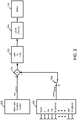
FIG. 2 is a block diagram view of an exemplary controller in which the harmonic regulator may be incorporated; -
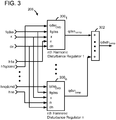
FIG. 3 is a block diagram of the harmonic regulator in which a plurality of individual harmonic regulators reside; -
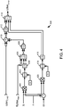
FIG. 4 is a block diagram of an individual harmonic regulator in accordance with the teachings herein; -
FIG. 5 is a block diagram of an embodiment of the source to harmonic frame transformation block ofFIG. 4 ; -
FIG. 6 is a block diagram of an embodiment of the harmonic to selected destination frame transformation block ofFIG. 4 ; -
FIG. 7 is a flowchart illustrating the steps performed to regulate one or more harmonics; -
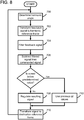
FIG. 8 is a flowchart illustrating the steps performed in one embodiment to regulate one or more harmonics at low speeds; -
FIGS. 9a-9e are simulated waveforms that illustrate an example of regulating a first harmonic in conjunction with a second harmonic; -
FIGS. 10a-10e are expanded views of the waveforms ofFIGS. 9a-9e ; -
FIGS. 11a-11e are simulated waveforms that illustrate an example of regulating a second harmonic in conjunction with the first harmonic ofFIGS. 9a-9e ; -
FIGS. 12a-12e are expanded views of the waveforms ofFIGS. 11a-11e ; -
FIG. 13 is an illustration showing the electrical torque estimate, the qdscontrol signal, the motor velocity, and a Fast Fourier Transform (FFT) of the motor velocity in an engine system operating at 300 rpm with the harmonic disturbance regulator disabled; -
FIG. 14 is an illustration showing the electrical torque estimate, the qdscontrol signal, the motor velocity, and a FFT of the motor velocity in an engine system ofFIG. 13 with the harmonic disturbance regulator enabled; -
FIG. 15 is an illustration showing the electrical torque estimate, the electrical torque command, the motor velocity, and a FFT of the motor velocity in an engine system operating at 600 rpm with the harmonic disturbance regulator disabled; and -
FIG. 16 is an illustration showing the electrical torque estimate, the electrical torque command, the motor velocity, and a FFT of the motor velocity in an engine system ofFIG. 15 with the harmonic disturbance regulator enabled. - While the harmonic regulator will be described in connection with certain embodiments, there is no intent to limit it to those embodiments. On the contrary, the intent is to cover all alternatives, modifications and equivalents within the scope of the appended claims.
- The harmonic regulator described herein regulates or eliminates harmonics that cause periodic torque disturbances. Referring initially to
FIG. 1 , anexemplary system 100 in which the present technology may operate is shown. The system includes a drive/controller 102 that receives three phase power at its input, converts it to a dc link, and controls motor 104 via power electronic switches (not shown). Themotor 104 drivesengine 106 throughcoupling 108. As previously described, the engine exerts a periodic torque disturbance on themotor shaft 110 due to cylinder compression/cam linkage interaction during rotation of theengine 106. - The drive/
controller 102 can be of any form. The drive/controller 102 typically includes some form of computer readable media. Computer readable media can be any available media that can be accessed by the drive/controller 102 and can include both volatile and nonvolatile media, removable and non-removable media. For the description that follows, the drive/controller 102 shall be in the form of a qd type of controller where the main control loops are used in the qd reference frame, also known as the dq reference frame. Turning now toFIG. 2 , the maincontrol loop block 200 receives inputs such as commanded speed, motor speed, motor acceleration, etc. and outputs a qds control signal, where the qds control signal contains a quadrature axis control signal and a direct axis control signal. The qds control signal is transformed into an uvw control signal by qds touvw block 202. The uvw control signal contains a control signals for each phase in the motor, which typically has three phases 120 degrees apart with respect to each other. The uvw control signal is used by uvw control block 204 to drivemotor 104. Generally, theuvw control block 204 consists of an inverter that supplies power to each motor phase via pulse-width modulation (PWM) and/or the like. - The
harmonic regulator 206 regulates one or more selected harmonics to specified values, which can be zero, by outputting a control signal that is added to the qds control signal whenswitch 208 is activated. Whileswitch 208 is shown, in one embodiment theharmonic regulator 206 is directly connected tosummer 210. Theharmonic regulator 206 contains a plurality of individual harmonic regulators 300n (seeFIG. 3 ). Theharmonic regulator 206 has an fqds input, an x input, and a dn input that are common to the plurality of individual harmonic regulators. The fqds input receives the vector feedback variable that is used in the main control loop and that has harmonic components due to the periodic torque disturbance. For example, in an application that controls mechanical torque disturbances (e.g., periodic torque disturbances), the fqds input could be motor acceleration, having, in the source frame, q axis magnitude only, or in an application for electrical voltage disturbance rejection (e.g., removing frequency dependent current harmonics due to inverter deadtime distortion), current feedback, potentially having both q and d axis magnitudes in the stationary reference frame. The x input is the angular position estimate of the fqds input upon which the harmonics are based and it sets the fundamental reference frame for the harmonics. The dn input is used as a "destination minus source" harmonic difference number for the output. For example a dn set to 1 when the source is the stationary frame sets the output to be in the first harmonic reference frame (i.e., synchronous fundamental reference frame) while a dn set to 0 sets the output to be in the stationary reference frame. The remaining multiple harmonic regulator inputs h1 through hn and fqdcmd1 through fqdcmdn are the harmonic numbers being regulated and the qd vector magnitude to which the harmonics are being controlled, respectively. A value of zero for the magnitude of these vectors causes the controller to regulate the associated harmonics to zero. The harmonics h1 through hn to be regulated may be determined by an understanding of the nature of the system being controlled or by analyzing the disturbance using a Fast Fourier Transform or by other experimental methods. The outputs of each of the individual harmonic regulators are summed at summing block 302 (FIG. 3 ) and the summed output, fqddncomp, is summed with the qds control signal atsummer 210. In the case where the fqds signal has only q axis magnitude, only the q axis component of the output is summed and the d axis component is held to zero. - Turning now to
FIG. 4 in conjunction withFIG. 7 , an embodiment of theharmonic regulator 300 is illustrated. Atblocks 400 to 402, the x input and harmonic number h being regulated are multiplied (block 400) and the modulo 2π is derived (block 402) to obtain the angle θ (theta) at which the harmonic being regulated is with respect to the stationary reference frame (step 700). The angle θ is used to derive the sine and cosine functions (block 404) used in the source to harmonic frame transformation block 406 (seeFIG. 5 ) to transform the fqds vector feedback variables into the harmonic frame of harmonic number h (step 702). For example, if the fifth harmonic is being regulated in aharmonic regulator 300, the fqds feedback variable would be transformed into the harmonic frame of the fifth harmonic. The resulting qdh variables are low pass filtered viafilter block 408 to reduce or eliminate other frequencies present in the qdh variables so that theharmonic regulator 300 primarily regulates the harmonic of interest (step 704). Alternatively, bandpass filters could be implemented in the source reference frame prior to transformation to the harmonic reference frame. The resulting filtered qdh values are subtracted from the commanded qd values at summer 410 (step 706). The resulting error is regulated with a qd PI regulator (block 412) (step 708) and transformed (block 414 - seeFIG. 6 ) to the reference frame selected via the dn input (step 710). The sine and cosine functions used inblock 414 are derived fromblock 416, which has an input angle derived from the modulo 2π (block 418) of the x input multiplied (at block 420) by the harmonic number minus the dn input value. The fqddncomp value for the selected harmonic is summed with other values, if any, at summing block 302 (FIG. 3 ), resulting in the fqddncomp output value ofharmonic regulator 206. - Note that at low engine speeds, harmonics can be difficult to discern due to the "crowding" of harmonics due to the low fundamental frequency of the system at low speed. In one embodiment, when the engine speed drops below a predetermined speed, the PI block is latched and the qd values are kept to their values that were at or above the predetermined speed (step 712 - see
FIG. 8 ). Tests have shown that regulating the harmonics with the latched value is better than if the harmonic disturbance regulator is completely disabled. - Turning now to
FIGS. 9a-12e , a simulated example of regulating two harmonics is shown.FIGS. 10a-10e andFIGS. 12a-12e are expanded views of the waveforms ofFIGS 9a-9e and11a-11e respectively.FIGS. 9a and11a are the qd acceleration feedback signals that are quantized similar to how the signals would be when an incremental encoder is used andFIGS. 10a and12a are expanded views ofFIGS. 9a and11a , respectively.FIGS. 9b and11b are the transformed qd acceleration signals after being transformed into the harmonic reference frame of harmonic h1 and h2, respectively.FIGS. 10b and12b are expanded views ofFIGS. 9b and11b , respectively.FIGS. 9c and11c are the filtered and transformed qd acceleration signals. It can be seen how the filtered terms for both harmonics (i.e., the acceleration errors in this example) are forced to zero by the PI regulator outputs.FIGS. 10c and12c are expanded views ofFIGS. 9c and11c , respectively.FIGS. 9d and11d are the filtered and transformed qd acceleration signals after PI regulated.FIGS. 10d and12d are expanded views ofFIGS. 9d and11d , respectively. It can be seen how each PI regulator output in the harmonic frame corresponds to a different magnitude and phase for each harmonic.FIGS. 9e and11e are the PI regulated qd acceleration signals after being transformed back into the reference frame ofFIGS. 9a and11a .FIGS. 10e and12e are expanded views ofFIGS. 9e and11e , respectively. - Turning now to
FIGS. 13 and 14 , an example of regulating the harmonics in a test system of a four cylinder, four cycle engine operating at 300 rpm is illustrated.Waveform 1300 is the electrical torque estimate,waveform 1302 is the qdscontrol signal (FIG. 2 ),waveform 1304 is the motor velocity, andwaveform 1306 is a FFT of motor velocity.FIG. 13 illustrates the waveforms with the harmonic disturbance regulator disabled. Large peak values at several harmonics can clearly be seen in the FFT of the velocity. When the harmonic disturbance regulator is enabled with the regulation setpoint set to a value of zero for the 2nd, 4th, 6th, 8th, 12th and 16th harmonics, it can be seen inFIG. 14 that the regulated harmonics have been decoupled in the system and that the motor velocity has little, if any, ripple. As a result, the periodic torque disturbance effects have been reduced and/or eliminated. -
FIGS. 15 and 16 provide an example of regulating harmonics in the same engine system operating at 600 rpm.Waveform 1500 is the electrical torque estimate,waveform 1502 is the qdscontrol signal (FIG. 2 ),waveform 1504 is the motor velocity, andwaveform 1506 is a FFT of motor velocity.FIG. 15 illustrates the waveforms with the harmonic disturbance regulator disabled. Large peak values at several harmonics can clearly be seen in the FFT of the velocity. When the harmonic disturbance regulator is enabled with the regulation setpoint set to a value of zero for the 2nd, 4th, 8th and 12th harmonics being regulated, it can be seen inFIG. 16 that the regulated harmonics have been decoupled in the system and that the motor velocity has little, if any, ripple. As a result, the periodic torque disturbance effects have been reduced and/or eliminated. - From the foregoing, it can be seen that periodic torque disturbances can be regulated with the harmonic disturbance regulator described herein. The transformation into the harmonic reference frame allows a controller to effectively operate on dc rather than time variant signals. This isolates the controller from time variant waveforms and therefore minimizes the limitation of controller frequency response and phase shift on torque and speed.
- The use of the terms "a" and "an" and "the" and similar referents in the context of describing the invention (especially in the context of the following claims) are to be construed to cover both the singular and the plural, unless otherwise indicated herein or clearly contradicted by context. The terms "comprising," "having," "including," and "containing" are to be construed as open-ended terms (i.e., meaning "including, but not limited to,") unless otherwise noted. Recitation of ranges of values herein are merely intended to serve as a shorthand method of referring individually to each separate value falling within the range, unless otherwise indicated herein, and each separate value is incorporated into the specification as if it were individually recited herein. All methods described herein can be performed in any suitable order unless otherwise indicated herein or otherwise clearly contradicted by context. The use of any and all examples, or exemplary language (e.g., "such as") provided herein, is intended merely to better illuminate the invention and does not pose a limitation on the scope of the invention unless otherwise claimed. No language in the specification should be construed as indicating any non-claimed element as essential to the practice of the invention.
- Preferred embodiments of this invention are described herein, including the best mode known to the inventor for carrying out the invention. Variations of those preferred embodiments may become apparent to those of ordinary skill in the art upon reading the foregoing description. The inventor expects skilled artisans to employ such variations as appropriate, and the inventor intends for the invention to be practiced otherwise than as specifically described herein. Accordingly, this invention includes all modifications and equivalents of the subject matter recited in the claims appended hereto as permitted by applicable law.
Claims (13)
- A method to regulate each harmonic of a plurality of harmonics in a system (100) having a periodic disturbance to a commanded value (qdsnCMD) and the system has a rotating load (106) adapted to operate at speeds in a speed range, the method comprising the steps of:
for each one of the plurality of harmonics:transforming (702) a feedback signal having at least one harmonic component due to the one of the plurality of harmonics from a source reference frame (qds) to a harmonic reference frame (qde) of the one of the plurality of harmonics to form a qd feedback signal (fqdssFBK);subtracting (706) the qd feedback signal (fqdssFBK) from the commanded value (qdsnCMD) to form a qd signal;regulating (708) the qd signal wherein the step of regulating the qd signal comprises the steps of:regulating the qd signal with a proportional integral (PI) regulator (412) at rotational speeds above a predetermined value; characterised in thatwhen the rotational speed goes below the predetermined value, bypassing the PI regulator and keeping (712) the qd signal at q and d values that were at or above the predetermined speed;transforming (710) the regulated qd signal to a destination reference frame to form a compensation signal (qdsdncomp); andadding (210) the compensation signal (qdsdncomp) to a control signal (qdscontrol) to form a qd control signal to drive the one of the plurality of harmonics towards the commanded value (qdsnCMD). - The method of claim 1 wherein the step of transforming the feedback signal includes the step of determining a harmonic angle of the one of the plurality of harmonics, and wherein the step of determining the harmonic angle may comprise the steps of:determining a value of the modulo 2π of a phase of the feedback signal multiplied by a harmonic number of the at least one harmonic; andsetting the harmonic angle to the value.
- The method of claim 1 further comprising the step of filtering the qd feedback signal, and wherein the step of filtering the qd feedback signal may comprise the step of filtering the feedback signal in the harmonic reference frame, or comprise the step of filtering the qd feedback signal with a low pass filter.
- The method of claim 1 wherein the step of regulating the qd signal comprises the step of regulating the qd signal using a proportional integral regulator.
- The method of claim 1 wherein the step of transforming the regulated qd signal to a destination reference frame comprises the step of transforming the regulated qd signal to the destination reference frame based upon a destination harmonic number.
- The method of claim 1 wherein the system has harmonics due to inverter deadtime distortion and wherein the qd feedback signal is a qd current feedback signal.
- A computer-readable medium having computer executable instructions which, when executed on a drive/controller (102) within a system (100) having a periodic disturbance to a commanded value and having a rotating load adapted to operate at speeds in a speed range, performs the steps of claim 1 in order to regulate each harmonic of a plurality of harmonics in the system (100).
- The computer-readable medium of claim 7 having further computer-executable instructions for performing the step comprising determining a harmonic angle of the at least one harmonic, and wherein the step of determining the harmonic angle may comprise the steps of:determining a value of the modulo 2π of a phase element of the feedback signal multiplied by a harmonic number of the at least one harmonic; andsetting the harmonic angle to the value.
- The computer-readable medium of claim 7 having further executable instructions for performing the step of filtering the qd feedback signal, and
wherein the step of filtering the qd feedback signal may comprise the step of filtering the feedback signal in the harmonic reference frame, or comprise the step of filtering the qd feedback signal with a low pass filter. - The computer-readable medium of claim 7 wherein the step of regulating the qd signal comprises the step of regulating the qd signal using a proportional integral regulator.
- The computer-readable medium of claim 7 wherein the step of transforming the regulated qd signal to a destination reference frame comprises the step of transforming the regulated qd signal to the destination reference frame based upon a destination harmonic number.
- The computer-readable medium of claim 7 wherein the system has a rotating load adapted to operate at speeds in a speed range and wherein the step of regulating the qd signal comprises the steps of:regulating the qd signal with a proportional integral (PI) regulator at rotational speeds above a predetermined value; andwhen the rotational speed goes below the predetermined value, bypassing the PI regulator and keeping the qd signal at q and d values at values that were at or above the predetermined speed.
- The computer-readable medium of claim 7 wherein the system has harmonics due to inverter deadtime distortion and wherein the qd feedback signal is a qd current feedback signal.
Applications Claiming Priority (2)
| Application Number | Priority Date | Filing Date | Title |
|---|---|---|---|
| US11/552,333 US7545113B2 (en) | 2006-10-24 | 2006-10-24 | Harmonic disturbance regulator |
| PCT/US2007/082045 WO2008051884A2 (en) | 2006-10-24 | 2007-10-22 | Harmonic disturbance regulator |
Publications (3)
| Publication Number | Publication Date |
|---|---|
| EP2084586A2 EP2084586A2 (en) | 2009-08-05 |
| EP2084586A4 EP2084586A4 (en) | 2017-08-16 |
| EP2084586B1 true EP2084586B1 (en) | 2018-12-26 |
Family
ID=39317275
Family Applications (1)
| Application Number | Title | Priority Date | Filing Date |
|---|---|---|---|
| EP07844485.8A Active EP2084586B1 (en) | 2006-10-24 | 2007-10-22 | Harmonic disturbance regulator |
Country Status (8)
| Country | Link |
|---|---|
| US (1) | US7545113B2 (en) |
| EP (1) | EP2084586B1 (en) |
| JP (1) | JP4451928B2 (en) |
| KR (1) | KR101029481B1 (en) |
| CA (1) | CA2667182C (en) |
| DK (1) | DK2084586T3 (en) |
| HU (1) | HUE043164T2 (en) |
| WO (1) | WO2008051884A2 (en) |
Families Citing this family (5)
| Publication number | Priority date | Publication date | Assignee | Title |
|---|---|---|---|---|
| US20150100139A1 (en) * | 2013-10-03 | 2015-04-09 | Hamilton Sundstrand Corporation | Frequency shifted pi controller |
| RU2650341C1 (en) * | 2016-12-06 | 2018-04-11 | федеральное государственное бюджетное образовательное учреждение высшего образования "Ивановский государственный энергетический университет имени В.И. Ленина" (ИГЭУ) | Device for elimination of influence of harmonic perturbations of load moment in electromechanical system |
| JP6849000B2 (en) * | 2019-03-14 | 2021-03-24 | ダイキン工業株式会社 | Direct power converter |
| CN111835258B (en) * | 2020-07-27 | 2023-04-18 | 广东希塔变频技术有限公司 | Motor drive control method and device and parking air conditioner controller |
| CN112821738B (en) * | 2021-02-24 | 2021-12-10 | 深圳市正浩创新科技股份有限公司 | Harmonic compensation device and method, rectifier, inverter, and electronic apparatus |
Family Cites Families (43)
| Publication number | Priority date | Publication date | Assignee | Title |
|---|---|---|---|---|
| US3628123A (en) | 1970-03-11 | 1971-12-14 | Westinghouse Electric Corp | Apparatus for harmonic neutralization of inverters |
| US4876634A (en) | 1988-07-01 | 1989-10-24 | Westinghouse Electric Corp. | Multi-pulse converter system |
| US5124904A (en) | 1990-08-17 | 1992-06-23 | Westinghouse Electric Corp. | Optimized 18-pulse type AC/DC, or DC/AC, converter system |
| ES2071730T3 (en) * | 1990-12-10 | 1995-07-01 | Asea Brown Boveri | PROCEDURE AND DEVICE FOR THE ELIMINATION OR REDUCTION OF HARMONICS AND / OR OF RESONANCE OSCILLATIONS. |
| US5148357A (en) | 1991-10-07 | 1992-09-15 | Westinghouse Electric Corp. | Auto-connected hexagon transformer for a 12-pulse converter |
| WO1993023914A1 (en) | 1992-05-11 | 1993-11-25 | Electric Power Research Institute | Harmonic blocking converter system |
| US5465203A (en) | 1993-06-18 | 1995-11-07 | Electric Power Research Institute, Inc. | Hybrid series active/parallel passive power line conditioner with controlled harmonic injection |
| US5585709A (en) | 1993-12-22 | 1996-12-17 | Wisconsin Alumni Research Foundation | Method and apparatus for transducerless position and velocity estimation in drives for AC machines |
| US5455759A (en) | 1994-06-24 | 1995-10-03 | Paice; Derek A. | Symmetrical, phase-shifting, fork transformer |
| US5568371A (en) | 1994-09-29 | 1996-10-22 | Texas A&M University System | Active harmonic power filter apparatus and method |
| US5513090A (en) | 1994-11-15 | 1996-04-30 | Electric Power Research Institute, Inc. | Hybrid series active, parallel passive, power line conditioner for harmonic isolation between a supply and a load |
| US5798631A (en) * | 1995-10-02 | 1998-08-25 | The State Of Oregon Acting By And Through The State Board Of Higher Education On Behalf Of Oregon State University | Performance optimization controller and control method for doubly-fed machines |
| US5619407A (en) | 1996-02-06 | 1997-04-08 | Robicon Corporation | Autotransformer |
| US5731965A (en) | 1996-06-21 | 1998-03-24 | Wisconsin Alumni Research Foundation | Power line harmonic reduction by hybrid parallel active/passive filter system with square wave inverter and DC bus control |
| US5781428A (en) | 1997-03-03 | 1998-07-14 | Paice; Derek A. | Transformer for 12-pulse series connection of converters |
| DE19724946B4 (en) * | 1997-06-12 | 2005-09-15 | Siemens Ag | Method and device for speed control of a sensorless, field-oriented operated asynchronous machine |
| US6028405A (en) | 1998-01-14 | 2000-02-22 | Yaskawa Electric America, Inc. | Variable frequency drive noise attenuation circuit |
| US6087738A (en) | 1998-08-20 | 2000-07-11 | Robicon Corporation | Variable output three-phase transformer |
| US6101113A (en) | 1999-12-02 | 2000-08-08 | Paice; Derek A | Transformers for multipulse AC/DC converters |
| US6191968B1 (en) | 2000-03-23 | 2001-02-20 | Derek A Paice | Wye connected 3-phase to 9-phase auto-transformer with reduced winding currents |
| US6249443B1 (en) | 2000-07-14 | 2001-06-19 | Rockwell Technologies, Llc | Nine-phase transformer |
| US6335872B1 (en) | 2000-07-14 | 2002-01-01 | Rockwell Automation Technologies, Inc. | Nine-phase transformer |
| US6198647B1 (en) | 2000-07-28 | 2001-03-06 | Rockwell Technologies, Llc | Twelve-phase transformer configuration |
| JP3852289B2 (en) * | 2001-02-16 | 2006-11-29 | 日産自動車株式会社 | Motor control device |
| EP1211798B1 (en) | 2000-11-22 | 2018-01-10 | Nissan Motor Co., Ltd. | Motor control apparatus and motor control method |
| US6498736B1 (en) | 2001-03-27 | 2002-12-24 | Baldor Electric Company | Harmonic filter with low cost magnetics |
| US6650557B2 (en) | 2001-04-27 | 2003-11-18 | Honeywell International Inc. | 18-pulse rectification system using a wye-connected autotransformer |
| US6385064B1 (en) | 2001-05-07 | 2002-05-07 | Rockwell Technologies, Llc | Harmonic blocking reactor for nine-phase converter system |
| JP3582505B2 (en) | 2001-09-10 | 2004-10-27 | 日産自動車株式会社 | Motor control device |
| US6472775B1 (en) | 2001-11-30 | 2002-10-29 | Ballard Power Systems Corporation | Method and system for eliminating certain harmonics in a distributed power system |
| US6525951B1 (en) | 2002-01-25 | 2003-02-25 | Derek Albert Paice | Simplified wye connected 3-phase to 9-phase auto-transformer |
| FR2842962B1 (en) | 2002-07-26 | 2004-12-03 | Technofan | INTERFACE FOR SUPPLYING A LOAD FROM AN ELECTRICAL SUPPLY NETWORK |
| US6894454B2 (en) | 2002-10-10 | 2005-05-17 | General Motors Corporation | Position sensorless control algorithm for AC machine |
| JP3928575B2 (en) * | 2003-04-07 | 2007-06-13 | 日産自動車株式会社 | Motor control device |
| US6950322B2 (en) | 2003-04-10 | 2005-09-27 | Rsm Electron Power, Inc. | Regulated AC to DC converter for aerospace applications |
| US6984960B2 (en) * | 2003-08-05 | 2006-01-10 | General Motors Corporation | Methods and apparatus for current control of a three-phase voltage source inverter in the overmodulation region |
| US7049921B2 (en) | 2003-08-12 | 2006-05-23 | Owen Donald W | Auto-transformer for use with multiple pulse rectifiers |
| US7106024B2 (en) * | 2003-09-12 | 2006-09-12 | Rockwell Automation Technologies, Inc. | Filter with increased first harmonic response and reduced phase shift in a wide frequency band for encoderless drive applications |
| US6995993B2 (en) | 2003-10-14 | 2006-02-07 | Honeywell International, Inc. | Rectification system for improving power quality of electrical power systems |
| JP2005328691A (en) | 2004-04-15 | 2005-11-24 | Denso Corp | Motor control device |
| US6982884B1 (en) | 2004-08-23 | 2006-01-03 | Derek Albert Paice | Autotransformers to parallel AC to DC converters |
| US7095636B2 (en) | 2004-09-15 | 2006-08-22 | Honeywell International Inc. | Electromagnetic interference filter for an autotransformer |
| US7193387B1 (en) * | 2006-03-14 | 2007-03-20 | Rockwell Automation Technologies, Inc. | System and method for motor speed estimation using hybrid model reference adaptive system |
-
2006
- 2006-10-24 US US11/552,333 patent/US7545113B2/en active Active
-
2007
- 2007-10-22 KR KR1020097009078A patent/KR101029481B1/en not_active Expired - Fee Related
- 2007-10-22 DK DK07844485.8T patent/DK2084586T3/en active
- 2007-10-22 HU HUE07844485A patent/HUE043164T2/en unknown
- 2007-10-22 JP JP2009534791A patent/JP4451928B2/en active Active
- 2007-10-22 EP EP07844485.8A patent/EP2084586B1/en active Active
- 2007-10-22 WO PCT/US2007/082045 patent/WO2008051884A2/en not_active Ceased
- 2007-10-22 CA CA2667182A patent/CA2667182C/en active Active
Non-Patent Citations (1)
| Title |
|---|
| None * |
Also Published As
| Publication number | Publication date |
|---|---|
| CA2667182C (en) | 2010-06-22 |
| WO2008051884A3 (en) | 2008-07-03 |
| US7545113B2 (en) | 2009-06-09 |
| CA2667182A1 (en) | 2008-05-02 |
| WO2008051884A2 (en) | 2008-05-02 |
| KR101029481B1 (en) | 2011-04-18 |
| DK2084586T3 (en) | 2019-03-18 |
| US20080180975A1 (en) | 2008-07-31 |
| EP2084586A2 (en) | 2009-08-05 |
| KR20090089299A (en) | 2009-08-21 |
| JP2010508801A (en) | 2010-03-18 |
| HUE043164T2 (en) | 2019-08-28 |
| JP4451928B2 (en) | 2010-04-14 |
| EP2084586A4 (en) | 2017-08-16 |
Similar Documents
| Publication | Publication Date | Title |
|---|---|---|
| KR101485988B1 (en) | Motor control device | |
| EP2206233B1 (en) | Bus disturbance regulator | |
| DK2084586T3 (en) | Over Oscillation disturbance regulator | |
| EP4097841A1 (en) | Method and device for controlling an electric machine | |
| JP2013099131A (en) | Power conversion device | |
| CN114731134B (en) | Methods and apparatus for regulating motors | |
| DE112019007063B4 (en) | SPEED ESTIMATOR FOR AC MOTOR, DRIVE DEVICE FOR AC MOTOR, REFRIGERATING COMPRESSOR AND REFRIGERATING CYCLE DEVICE | |
| EP4097839A1 (en) | Method and device for controlling the rotational speed of an electric machine for the drive of a compressor of a heat pump | |
| US12081156B2 (en) | Method and device for regulating an electric machine | |
| CN117997199A (en) | Torque fluctuation suppression method and system for permanent magnet synchronous motor | |
| CN116388637A (en) | Noise suppression method and device for permanent magnet synchronous motor | |
| CN114731133B (en) | Method and device for regulating an electric motor | |
| Majchrzak et al. | Comparison of FOC and DTC methods for a Matrix Converter-fed permanent magnet synchronous motor | |
| CN120415190B (en) | Stability control methods, devices and systems for motor drive systems and permanent magnet synchronous motors | |
| DE102023106516B4 (en) | Vehicle with a multi-phase electric motor that drives the vehicle, which has a device for damping harmonics. | |
| Su et al. | Suppression control method for torque vibration of three-phase HB-type stepping motor utilizing feedforward control | |
| Cupertino et al. | A simple stator flux oriented induction motor control | |
| WO2026092995A1 (en) | Method and device for controlling an electric machine, and electric drive system | |
| Onwuso et al. | Derivation of Improved Induction Machine Model |
Legal Events
| Date | Code | Title | Description |
|---|---|---|---|
| PUAI | Public reference made under article 153(3) epc to a published international application that has entered the european phase |
Free format text: ORIGINAL CODE: 0009012 |
|
| 17P | Request for examination filed |
Effective date: 20090501 |
|
| AK | Designated contracting states |
Kind code of ref document: A2 Designated state(s): AT BE BG CH CY CZ DE DK EE ES FI FR GB GR HU IE IS IT LI LT LU LV MC MT NL PL PT RO SE SI SK TR |
|
| DAX | Request for extension of the european patent (deleted) | ||
| A4 | Supplementary search report drawn up and despatched |
Effective date: 20170714 |
|
| RIC1 | Information provided on ipc code assigned before grant |
Ipc: G05B 11/42 20060101AFI20170710BHEP Ipc: H02P 29/50 20160101ALI20170710BHEP Ipc: H02P 21/22 20160101ALI20170710BHEP Ipc: H02M 1/12 20060101ALI20170710BHEP |
|
| REG | Reference to a national code |
Ref country code: DE Ref legal event code: R079 Ref document number: 602007057268 Country of ref document: DE Free format text: PREVIOUS MAIN CLASS: G05B0013020000 Ipc: G05B0011420000 |
|
| GRAP | Despatch of communication of intention to grant a patent |
Free format text: ORIGINAL CODE: EPIDOSNIGR1 |
|
| STAA | Information on the status of an ep patent application or granted ep patent |
Free format text: STATUS: GRANT OF PATENT IS INTENDED |
|
| RIC1 | Information provided on ipc code assigned before grant |
Ipc: H02M 1/12 20060101ALI20180615BHEP Ipc: G05B 11/42 20060101AFI20180615BHEP Ipc: H02P 21/22 20160101ALI20180615BHEP Ipc: H02P 29/50 20160101ALI20180615BHEP |
|
| INTG | Intention to grant announced |
Effective date: 20180718 |
|
| GRAS | Grant fee paid |
Free format text: ORIGINAL CODE: EPIDOSNIGR3 |
|
| GRAA | (expected) grant |
Free format text: ORIGINAL CODE: 0009210 |
|
| STAA | Information on the status of an ep patent application or granted ep patent |
Free format text: STATUS: THE PATENT HAS BEEN GRANTED |
|
| AK | Designated contracting states |
Kind code of ref document: B1 Designated state(s): AT BE BG CH CY CZ DE DK EE ES FI FR GB GR HU IE IS IT LI LT LU LV MC MT NL PL PT RO SE SI SK TR |
|
| REG | Reference to a national code |
Ref country code: GB Ref legal event code: FG4D |
|
| REG | Reference to a national code |
Ref country code: CH Ref legal event code: EP |
|
| REG | Reference to a national code |
Ref country code: AT Ref legal event code: REF Ref document number: 1082249 Country of ref document: AT Kind code of ref document: T Effective date: 20190115 |
|
| REG | Reference to a national code |
Ref country code: DE Ref legal event code: R096 Ref document number: 602007057268 Country of ref document: DE |
|
| REG | Reference to a national code |
Ref country code: IE Ref legal event code: FG4D |
|
| REG | Reference to a national code |
Ref country code: RO Ref legal event code: EPE |
|
| REG | Reference to a national code |
Ref country code: DK Ref legal event code: T3 Effective date: 20190311 |
|
| REG | Reference to a national code |
Ref country code: SE Ref legal event code: TRGR |
|
| REG | Reference to a national code |
Ref country code: NL Ref legal event code: FP |
|
| PG25 | Lapsed in a contracting state [announced via postgrant information from national office to epo] |
Ref country code: LT Free format text: LAPSE BECAUSE OF FAILURE TO SUBMIT A TRANSLATION OF THE DESCRIPTION OR TO PAY THE FEE WITHIN THE PRESCRIBED TIME-LIMIT Effective date: 20181226 Ref country code: BG Free format text: LAPSE BECAUSE OF FAILURE TO SUBMIT A TRANSLATION OF THE DESCRIPTION OR TO PAY THE FEE WITHIN THE PRESCRIBED TIME-LIMIT Effective date: 20190326 Ref country code: LV Free format text: LAPSE BECAUSE OF FAILURE TO SUBMIT A TRANSLATION OF THE DESCRIPTION OR TO PAY THE FEE WITHIN THE PRESCRIBED TIME-LIMIT Effective date: 20181226 |
|
| REG | Reference to a national code |
Ref country code: LT Ref legal event code: MG4D |
|
| REG | Reference to a national code |
Ref country code: DE Ref legal event code: R081 Ref document number: 602007057268 Country of ref document: DE Owner name: UNICO, LLC, FRANSKVILLE, US Free format text: FORMER OWNER: UNICO, INC., FRANKSVILLE, WI, US |
|
| RAP2 | Party data changed (patent owner data changed or rights of a patent transferred) |
Owner name: UNICO, LLC |
|
| PG25 | Lapsed in a contracting state [announced via postgrant information from national office to epo] |
Ref country code: GR Free format text: LAPSE BECAUSE OF FAILURE TO SUBMIT A TRANSLATION OF THE DESCRIPTION OR TO PAY THE FEE WITHIN THE PRESCRIBED TIME-LIMIT Effective date: 20190327 |
|
| REG | Reference to a national code |
Ref country code: CH Ref legal event code: NV Representative=s name: FIAMMENGHI-FIAMMENGHI, CH Ref country code: CH Ref legal event code: PFA Owner name: UNICO, LLC, US Free format text: FORMER OWNER: UNICO, INC., US |
|
| REG | Reference to a national code |
Ref country code: NL Ref legal event code: PD Owner name: UNICO, LLC; US Free format text: DETAILS ASSIGNMENT: CHANGE OF OWNER(S), CHANGE OF LEGAL ENTITY; FORMER OWNER NAME: UNICO, INC. Effective date: 20190528 |
|
| REG | Reference to a national code |
Ref country code: HU Ref legal event code: FH1C Free format text: FORMER REPRESENTATIVE(S): DANUBIA SZABADALMI ES JOGI IRODA KFT., HU Representative=s name: DANUBIA SZABADALMI ES JOGI IRODA KFT., HU Ref country code: HU Ref legal event code: GB9C Owner name: UNICO, LLC, US Free format text: FORMER OWNER(S): UNICO, INC., US |
|
| PG25 | Lapsed in a contracting state [announced via postgrant information from national office to epo] |
Ref country code: PT Free format text: LAPSE BECAUSE OF FAILURE TO SUBMIT A TRANSLATION OF THE DESCRIPTION OR TO PAY THE FEE WITHIN THE PRESCRIBED TIME-LIMIT Effective date: 20190426 Ref country code: PL Free format text: LAPSE BECAUSE OF FAILURE TO SUBMIT A TRANSLATION OF THE DESCRIPTION OR TO PAY THE FEE WITHIN THE PRESCRIBED TIME-LIMIT Effective date: 20181226 Ref country code: ES Free format text: LAPSE BECAUSE OF FAILURE TO SUBMIT A TRANSLATION OF THE DESCRIPTION OR TO PAY THE FEE WITHIN THE PRESCRIBED TIME-LIMIT Effective date: 20181226 |
|
| REG | Reference to a national code |
Ref country code: HU Ref legal event code: AG4A Ref document number: E043164 Country of ref document: HU |
|
| PG25 | Lapsed in a contracting state [announced via postgrant information from national office to epo] |
Ref country code: IS Free format text: LAPSE BECAUSE OF FAILURE TO SUBMIT A TRANSLATION OF THE DESCRIPTION OR TO PAY THE FEE WITHIN THE PRESCRIBED TIME-LIMIT Effective date: 20190426 Ref country code: SK Free format text: LAPSE BECAUSE OF FAILURE TO SUBMIT A TRANSLATION OF THE DESCRIPTION OR TO PAY THE FEE WITHIN THE PRESCRIBED TIME-LIMIT Effective date: 20181226 Ref country code: EE Free format text: LAPSE BECAUSE OF FAILURE TO SUBMIT A TRANSLATION OF THE DESCRIPTION OR TO PAY THE FEE WITHIN THE PRESCRIBED TIME-LIMIT Effective date: 20181226 |
|
| REG | Reference to a national code |
Ref country code: DE Ref legal event code: R097 Ref document number: 602007057268 Country of ref document: DE |
|
| PLBE | No opposition filed within time limit |
Free format text: ORIGINAL CODE: 0009261 |
|
| STAA | Information on the status of an ep patent application or granted ep patent |
Free format text: STATUS: NO OPPOSITION FILED WITHIN TIME LIMIT |
|
| 26N | No opposition filed |
Effective date: 20190927 |
|
| PG25 | Lapsed in a contracting state [announced via postgrant information from national office to epo] |
Ref country code: SI Free format text: LAPSE BECAUSE OF FAILURE TO SUBMIT A TRANSLATION OF THE DESCRIPTION OR TO PAY THE FEE WITHIN THE PRESCRIBED TIME-LIMIT Effective date: 20181226 |
|
| REG | Reference to a national code |
Ref country code: AT Ref legal event code: PC Ref document number: 1082249 Country of ref document: AT Kind code of ref document: T Owner name: UNICO, LLC, US Effective date: 20200128 |
|
| PG25 | Lapsed in a contracting state [announced via postgrant information from national office to epo] |
Ref country code: TR Free format text: LAPSE BECAUSE OF FAILURE TO SUBMIT A TRANSLATION OF THE DESCRIPTION OR TO PAY THE FEE WITHIN THE PRESCRIBED TIME-LIMIT Effective date: 20181226 |
|
| PG25 | Lapsed in a contracting state [announced via postgrant information from national office to epo] |
Ref country code: MC Free format text: LAPSE BECAUSE OF FAILURE TO SUBMIT A TRANSLATION OF THE DESCRIPTION OR TO PAY THE FEE WITHIN THE PRESCRIBED TIME-LIMIT Effective date: 20181226 |
|
| PG25 | Lapsed in a contracting state [announced via postgrant information from national office to epo] |
Ref country code: LU Free format text: LAPSE BECAUSE OF NON-PAYMENT OF DUE FEES Effective date: 20191022 |
|
| REG | Reference to a national code |
Ref country code: BE Ref legal event code: MM Effective date: 20191031 |
|
| REG | Reference to a national code |
Ref country code: AT Ref legal event code: UEP Ref document number: 1082249 Country of ref document: AT Kind code of ref document: T Effective date: 20181226 |
|
| PG25 | Lapsed in a contracting state [announced via postgrant information from national office to epo] |
Ref country code: BE Free format text: LAPSE BECAUSE OF NON-PAYMENT OF DUE FEES Effective date: 20191031 |
|
| PG25 | Lapsed in a contracting state [announced via postgrant information from national office to epo] |
Ref country code: IE Free format text: LAPSE BECAUSE OF NON-PAYMENT OF DUE FEES Effective date: 20191022 |
|
| PG25 | Lapsed in a contracting state [announced via postgrant information from national office to epo] |
Ref country code: CY Free format text: LAPSE BECAUSE OF FAILURE TO SUBMIT A TRANSLATION OF THE DESCRIPTION OR TO PAY THE FEE WITHIN THE PRESCRIBED TIME-LIMIT Effective date: 20181226 |
|
| PG25 | Lapsed in a contracting state [announced via postgrant information from national office to epo] |
Ref country code: MT Free format text: LAPSE BECAUSE OF FAILURE TO SUBMIT A TRANSLATION OF THE DESCRIPTION OR TO PAY THE FEE WITHIN THE PRESCRIBED TIME-LIMIT Effective date: 20181226 |
|
| P01 | Opt-out of the competence of the unified patent court (upc) registered |
Effective date: 20230420 |
|
| REG | Reference to a national code |
Ref country code: CH Ref legal event code: U11 Free format text: ST27 STATUS EVENT CODE: U-0-0-U10-U11 (AS PROVIDED BY THE NATIONAL OFFICE) Effective date: 20251101 |
|
| PGFP | Annual fee paid to national office [announced via postgrant information from national office to epo] |
Ref country code: HU Payment date: 20251007 Year of fee payment: 19 |
|
| PGFP | Annual fee paid to national office [announced via postgrant information from national office to epo] |
Ref country code: NL Payment date: 20251026 Year of fee payment: 19 |
|
| PGFP | Annual fee paid to national office [announced via postgrant information from national office to epo] |
Ref country code: DE Payment date: 20251029 Year of fee payment: 19 |
|
| PGFP | Annual fee paid to national office [announced via postgrant information from national office to epo] |
Ref country code: GB Payment date: 20251027 Year of fee payment: 19 |
|
| PGFP | Annual fee paid to national office [announced via postgrant information from national office to epo] |
Ref country code: AT Payment date: 20251029 Year of fee payment: 19 |
|
| PGFP | Annual fee paid to national office [announced via postgrant information from national office to epo] |
Ref country code: IT Payment date: 20251021 Year of fee payment: 19 Ref country code: FI Payment date: 20251027 Year of fee payment: 19 Ref country code: DK Payment date: 20251027 Year of fee payment: 19 |
|
| PGFP | Annual fee paid to national office [announced via postgrant information from national office to epo] |
Ref country code: FR Payment date: 20251027 Year of fee payment: 19 |
|
| PGFP | Annual fee paid to national office [announced via postgrant information from national office to epo] |
Ref country code: SE Payment date: 20251027 Year of fee payment: 19 Ref country code: CH Payment date: 20251101 Year of fee payment: 19 |
|
| PGFP | Annual fee paid to national office [announced via postgrant information from national office to epo] |
Ref country code: CZ Payment date: 20251007 Year of fee payment: 19 |
|
| PGFP | Annual fee paid to national office [announced via postgrant information from national office to epo] |
Ref country code: RO Payment date: 20251006 Year of fee payment: 19 |