EP2083740B1 - Protection assembly for a syringe - Google Patents
Protection assembly for a syringe Download PDFInfo
- Publication number
- EP2083740B1 EP2083740B1 EP07870237.0A EP07870237A EP2083740B1 EP 2083740 B1 EP2083740 B1 EP 2083740B1 EP 07870237 A EP07870237 A EP 07870237A EP 2083740 B1 EP2083740 B1 EP 2083740B1
- Authority
- EP
- European Patent Office
- Prior art keywords
- syringe
- cannula
- sheath
- protection assembly
- protection
- Prior art date
- Legal status (The legal status is an assumption and is not a legal conclusion. Google has not performed a legal analysis and makes no representation as to the accuracy of the status listed.)
- Active
Links
- 239000000463 material Substances 0.000 claims description 8
- 230000002427 irreversible effect Effects 0.000 claims description 3
- 230000000712 assembly Effects 0.000 description 4
- 238000000429 assembly Methods 0.000 description 4
- 230000001681 protective effect Effects 0.000 description 4
- 239000010408 film Substances 0.000 description 3
- 239000012530 fluid Substances 0.000 description 3
- 238000003860 storage Methods 0.000 description 3
- 208000030507 AIDS Diseases 0.000 description 2
- 208000031968 Cadaver Diseases 0.000 description 2
- 239000004698 Polyethylene Substances 0.000 description 2
- 238000011109 contamination Methods 0.000 description 2
- 229920000642 polymer Polymers 0.000 description 2
- 238000005507 spraying Methods 0.000 description 2
- XLYOFNOQVPJJNP-UHFFFAOYSA-N water Substances O XLYOFNOQVPJJNP-UHFFFAOYSA-N 0.000 description 2
- 241000700605 Viruses Species 0.000 description 1
- 238000004026 adhesive bonding Methods 0.000 description 1
- 238000005520 cutting process Methods 0.000 description 1
- 201000010099 disease Diseases 0.000 description 1
- 208000037265 diseases, disorders, signs and symptoms Diseases 0.000 description 1
- 208000006454 hepatitis Diseases 0.000 description 1
- 231100000283 hepatitis Toxicity 0.000 description 1
- 229920001903 high density polyethylene Polymers 0.000 description 1
- 239000004700 high-density polyethylene Substances 0.000 description 1
- 238000005259 measurement Methods 0.000 description 1
- 238000000034 method Methods 0.000 description 1
- -1 polyethylene Polymers 0.000 description 1
- 229920000573 polyethylene Polymers 0.000 description 1
- 239000007921 spray Substances 0.000 description 1
- 208000011580 syndromic disease Diseases 0.000 description 1
- 239000010409 thin film Substances 0.000 description 1
- 238000003466 welding Methods 0.000 description 1
Images

Classifications
-
- A—HUMAN NECESSITIES
- A61—MEDICAL OR VETERINARY SCIENCE; HYGIENE
- A61C—DENTISTRY; APPARATUS OR METHODS FOR ORAL OR DENTAL HYGIENE
- A61C1/00—Dental machines for boring or cutting ; General features of dental machines or apparatus, e.g. hand-piece design
- A61C1/08—Machine parts specially adapted for dentistry
- A61C1/16—Protecting caps for hand-pieces or angle-pieces
Landscapes
- Health & Medical Sciences (AREA)
- Oral & Maxillofacial Surgery (AREA)
- Dentistry (AREA)
- Epidemiology (AREA)
- Life Sciences & Earth Sciences (AREA)
- Animal Behavior & Ethology (AREA)
- General Health & Medical Sciences (AREA)
- Public Health (AREA)
- Veterinary Medicine (AREA)
- Infusion, Injection, And Reservoir Apparatuses (AREA)
- Dental Tools And Instruments Or Auxiliary Dental Instruments (AREA)
Description
La présente invention concerne un ensemble de protection pour une seringue.The present invention relates to a protection assembly for a syringe.
Par seringue, on entend un appareil utilisé notamment en art dentaire pour pulvériser à haute pression un fluide tel que par exemple de l'air et/ou de l'eau sur une zone dentaire traitée.By syringe means an apparatus used in particular in dentistry to spray at high pressure a fluid such as for example air and / or water on a treated tooth area.
On sait que des précautions doivent être prises pour éviter qu'une seringue ne soit contaminée par un patient ou ne contamine un patient avec une maladie contagieuse, notamment par la diffusion de virus tels que ceux de l'hépatite ou du syndrome immuno-déficitaire acquis (SIDA).It is known that precautions must be taken to prevent a syringe from being contaminated by a patient or from contaminating a patient with a contagious disease, in particular by the spread of viruses such as those of hepatitis or acquired immune deficiency syndrome. (AIDS).
Une manière de se prémunir contre une telle contamination consiste à stériliser la seringue avant chaque utilisation. Cette mesure n'est cependant pas toujours possible compte tenu de la taille ou de la géométrie des seringues. Ainsi, une autre manière de se prémunir d'une contamination consiste à utiliser un ensemble de protection jetable.One way to guard against such contamination is to sterilize the syringe before each use. However, this measurement is not always possible given the size or geometry of the syringes. Thus, another way to guard against contamination is to use a disposable protective package.
On a représenté sur la
Cet ensemble de protection comprend une canule 2 jetable dont une base 4 est destinée à être fixée sur une seringue, généralement par l'intermédiaire d'un adaptateur. L'ensemble de protection comprend également une gaine 6 formée d'un film souple enroulé sur lui-même à proximité de la base 4. Pour utiliser cet ensemble de protection, le praticien fixe la canule 2 sur une seringue et déroule la gaine 6 qui vient ainsi recouvrir le corps de seringue.This protection assembly comprises a
Le demandeur a constaté que cet ensemble de protection n'était pas d'un usage pratique. D'une part, le stockage d'une pluralité d'ensembles de protection est rendu délicat car les gaines enroulées ont tendance à s'accrocher entre elles. D'autre part, la mise en place de la gaine sur le corps de seringue est malaisée, le praticien tenant d'une main le corps de seringue ne disposant que d'une seule main pour dérouler la gaine.The plaintiff found that this protection package was not practical. On the one hand, the storage of a plurality of protection assemblies is made difficult because the wrapped sheaths tend to hang together. On the other hand, the introduction of the sheath on the syringe body is difficult, the practitioner holding in one hand the syringe body having only one hand to unwind the sheath.
Il en résulte que l'ensemble de protection selon l'art antérieur n'est pas satisfaisant pour le praticien.As a result, the protection assembly according to the prior art is unsatisfactory for the practitioner.
Le document
L'invention a pour but de remédier aux inconvénients des ensembles de protection connus.The object of the invention is to overcome the disadvantages of known protection assemblies.
A cette fin, l'invention a pour objet un ensemble de protection pour seringue, notamment dentaire, comprenant un corps de seringue, ledit ensemble de protection comprenant :
- une canule en un matériau élastiquement rigide comportant une base destinée à être fixée sur le corps de seringue, et
- une gaine en matériau souple destinée à recouvrir de manière lâche ledit corps de seringue,
- a cannula of an elastically rigid material having a base for attachment to the syringe body, and
- a sheath of flexible material for loosely covering said syringe body,
Par fixation irréversible, on entend que la gaine et la canule ne peuvent pas être séparées l'une de l'autre, sauf à détruire de manière irrémédiable l'ensemble de protection.By irreversible fixation, it is meant that the sheath and the cannula can not be separated from each other, except to irretrievably destroy the protection assembly.
Selon un mode de réalisation préféré, la gaine présente, à son extrémité opposée à celle fixée à la canule, une zone définie par une ligne de prédécoupage.According to a preferred embodiment, the sheath has, at its end opposite to that fixed to the cannula, an area defined by a pre-cut line.
De manière avantageuse, ladite zone est pourvue d'un orifice.Advantageously, said zone is provided with an orifice.
D'autres caractéristiques et avantages de l'invention apparaîtront à la lecture de la description qui suit d'un mode de réalisation, donné à titre illustratif mais non limitatif, en référence aux dessins annexés, sur lesquels :
- La
figure 1 , déjà décrite, illustre un ensemble de protection pour seringue selon l'état de la technique, - La
figure 2 illustre un ensemble de protection pour seringue selon l'invention, et - La
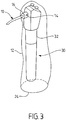
figure 3 illustre l'ensemble de protection de lafigure 2 après sa mise en place sur une seringue.
- The
figure 1 , already described, illustrates a protection assembly for syringe according to the state of the art, - The
figure 2 illustrates a protection assembly for a syringe according to the invention, and - The
figure 3 illustrates the whole protection of thefigure 2 after being put on a syringe.
On a représenté sur la
La canule 10 a une forme générale cylindrique, dont la section peut être notamment circulaire, ellipsoïdale, rectangulaire, etc, et comporte deux canaux (non représentés) destinés à la pulvérisation de fluides, tels que par exemple de l'air et de l'eau lorsque la canule est en position à l'extrémité d'un corps de seringue. A cette fin, la canule 10 comporte une marque de référence 14 pour faciliter l'orientation de ses canaux par rapport à ceux de la seringue par le praticien. La canule comporte également une base 16 pour permettre sa fixation, par exemple par engagement à frottement, sur le corps de seringue.The
La canule est réalisée en un matériau élastiquement déformable, de sorte que le praticien peut la plier pour l'orienter selon son besoin par rapport à la zone dentaire à traiter. Le matériau de la canule est de préférence un polymère, et par exemple un polyéthylène à haute densité tel que le matériau PE HD ERACLENE MR80 dont la densité est de l'ordre de 0,954 g/cm3. De manière typique, la section droite de la canule a une surface de l'ordre de 2 à 10 mm2.The cannula is made of an elastically deformable material, so that the practitioner can bend it to direct it according to his need with respect to the dental area to be treated. The material of the cannula is preferably a polymer, and for example a high density polyethylene such as PE HD ERACLENE MR80 material whose density is of the order of 0.954 g / cm 3 . Typically, the cross section of the cannula has an area of the order of 2 to 10 mm 2 .
La gaine 12 est destinée à recevoir le corps d'une seringue ou au moins une partie importante de celui-ci. Elle se présente, avant sa mise en place par le praticien, sous la forme d'un film souple formé de deux parois planes 18A, 18B. Elle comporte une extrémité qui est fixée à la canule 10 à proximité de sa base 16. Cette fixation peut être obtenue par tout moyen connu et en particulier par collage, soudage aux ultrasons, etc.The
La gaine 12 est formée d'un matériau souple, tel qu'un polymère, et se présente sous la forme d'un film mince. A titre d'exemple, on peut choisir un polyéthylène de densité 0,905 g/cm3 sous forme de film d'épaisseur 0,1 mm.The
La gaine 12 a par exemple une longueur de l'ordre de 25 cm et une largeur de l'ordre de 6 cm. Cette largeur est choisie afin que le corps de seringue puisse être introduits de manière lâche, c'est-à-dire sans frottement, dans la gaine entre les deux parois 18A et 18B.The
Comme représenté sur la
La forme plane de la gaine avant sa mise en place sur une seringue permet un stockage optimal de l'ensemble de protection. De plus, lorsque la gaine est dotée d'une ligne de prédécoupage 24 et d'un orifice 26, une pluralité d'ensembles de protection peuvent être stockés côte-à-côte, par exemple suspendus par leur orifice 26 sur un même axe. Un praticien peut ainsi saisir facilement un ensemble de protection en tirant sur la canule de manière à déchirer la gaine suivant la zone de prédécoupage 24.The flat shape of the sheath before its introduction on a syringe allows optimal storage of the protection assembly. In addition, when the sheath is provided with a
On a représenté sur la
La base 16 de la canule 10 est assujettie à un adaptateur du corps de seringue. Cette canule est déformée élastiquement par le praticien de manière à ce qu'il puisse atteindre la zone à traiter.The
Dans le mode de réalisation représenté, le corps de seringue est entièrement contenu dans la gaine 12 dont le praticien a écarté les deux parois pour permettre l'introduction du corps de seringue. La largeur de la gaine est choisie suffisante pour qu'une seringue classique puisse être introduite dans la gaine de manière lâche, c'est-à-dire sans frottement.In the embodiment shown, the syringe body is entirely contained in the
On comprend qu'un tel ensemble de protection est plus facile à mettre en place sur une seringue que les ensembles de protection selon l'art antérieur. De même, à la fin de l'utilisation de la seringue, il est particulièrement aisé de retirer l'ensemble de protection de la seringue.It is understood that such a protection assembly is easier to implement on a syringe than the protective assemblies according to the prior art. Similarly, at the end of the use of the syringe, it is particularly easy remove the protective assembly from the syringe.
L'ensemble de protection selon l'invention permet un stockage efficace et est d'usage particulièrement simple pour le praticien. En outre, étant jetable, il permet d'éviter de contaminer la seringue.The protection assembly according to the invention allows efficient storage and is particularly simple for the practitioner. In addition, being disposable, it avoids contaminating the syringe.
Claims (3)
- A protection assembly for a syringe (30), in particular dental, comprising a syringe body (32), said protection assembly comprising:- a cannula (10) made from a resiliently rigid material including a base (16) intended to be fastened on the syringe body, and- a sheath (12) made from a flexible material intended to cover said syringe body loosely,said sheath being fastened to said cannula near said base, said fastening being of the irreversible type,
characterized in that the sheath (12) is formed from two planar parallel walls (18A, 18B) and in that the cannula includes two channels and a reference mark (14) to facilitate the orientation of the channels of said cannula relative to those of the syringe. - The protection assembly according to claim 1, characterized in that the sheath (12) has, at its end opposite that fastened to the cannula, a zone (22) defined by a precut line (24).
- The protection assembly according to claim 2, characterized in that it comprises an orifice (26) in said zone (22).
Applications Claiming Priority (2)
| Application Number | Priority Date | Filing Date | Title |
|---|---|---|---|
| FR0609614A FR2908037B1 (en) | 2006-11-03 | 2006-11-03 | PROTECTIVE ASSEMBLY FOR SYRINGE |
| PCT/FR2007/001817 WO2008065269A1 (en) | 2006-11-03 | 2007-11-02 | Protection assembly for a syringe |
Publications (2)
| Publication Number | Publication Date |
|---|---|
| EP2083740A1 EP2083740A1 (en) | 2009-08-05 |
| EP2083740B1 true EP2083740B1 (en) | 2018-10-24 |
Family
ID=38057312
Family Applications (1)
| Application Number | Title | Priority Date | Filing Date |
|---|---|---|---|
| EP07870237.0A Active EP2083740B1 (en) | 2006-11-03 | 2007-11-02 | Protection assembly for a syringe |
Country Status (7)
| Country | Link |
|---|---|
| US (1) | US20080105267A1 (en) |
| EP (1) | EP2083740B1 (en) |
| CN (1) | CN101172054A (en) |
| ES (1) | ES2706291T3 (en) |
| FR (1) | FR2908037B1 (en) |
| TW (1) | TW200831148A (en) |
| WO (1) | WO2008065269A1 (en) |
Families Citing this family (2)
| Publication number | Priority date | Publication date | Assignee | Title |
|---|---|---|---|---|
| WO2015187111A1 (en) | 2014-06-06 | 2015-12-10 | Özkarsli Şükrü Fatih | Protective cover coating device |
| DE102018104375A1 (en) * | 2018-02-27 | 2019-08-29 | Kulzer Gmbh | Protective cover as a cover for a medical syringe |
Family Cites Families (13)
| Publication number | Priority date | Publication date | Assignee | Title |
|---|---|---|---|---|
| US4810194A (en) * | 1987-11-04 | 1989-03-07 | Snedden John E | Disposable antiseptic dental shield |
| US4998880A (en) * | 1987-11-09 | 1991-03-12 | Robert Nerli | Dental syringe safety sheath apparatus |
| US5236355A (en) * | 1988-12-22 | 1993-08-17 | American Cyanamid Company | Apparatus for the treatment of periodontal disease |
| US5807107A (en) * | 1995-10-20 | 1998-09-15 | Barrier Supply | Dental infection control system |
| WO1998038943A1 (en) * | 1997-03-05 | 1998-09-11 | Heilbrunn Karl E | Disposable protective barriers for use with dental instruments |
| US5908296A (en) * | 1997-12-16 | 1999-06-01 | Minnesota Mining & Manufacturing Co. | Dental air-water syringe with water purifying device |
| US6179159B1 (en) * | 1998-01-26 | 2001-01-30 | Mariruth D. Gurley | Communicable disease barrier digit cover and dispensing package therefor |
| US6594971B1 (en) * | 1998-12-30 | 2003-07-22 | Ethicon, Inc. | Sterile packaging for flexible endoscopes |
| JP3845304B2 (en) * | 2001-02-02 | 2006-11-15 | ペンタックス株式会社 | Endoscope holding device |
| US6981618B2 (en) * | 2001-10-18 | 2006-01-03 | Ivoclar Vivadent Ag | Container assembly for a substance to be applied |
| US7004756B2 (en) * | 2003-01-24 | 2006-02-28 | Ultradent Products, Inc. | Pre-shaped dental trays and treatment devices and methods that utilize such dental trays |
| CA2518281A1 (en) * | 2004-09-07 | 2006-03-07 | Foodhandler, Inc. | Mountable glove dispenser |
| JP2006271651A (en) * | 2005-03-29 | 2006-10-12 | Matsumoto Shika Univ | Needle component for liquid injection, and production method thereof |
-
2006
- 2006-11-03 FR FR0609614A patent/FR2908037B1/en active Active
-
2007
- 2007-09-17 US US11/856,117 patent/US20080105267A1/en not_active Abandoned
- 2007-10-19 TW TW096139351A patent/TW200831148A/en unknown
- 2007-11-02 WO PCT/FR2007/001817 patent/WO2008065269A1/en active Application Filing
- 2007-11-02 CN CNA2007101671997A patent/CN101172054A/en active Pending
- 2007-11-02 ES ES07870237T patent/ES2706291T3/en active Active
- 2007-11-02 EP EP07870237.0A patent/EP2083740B1/en active Active
Non-Patent Citations (1)
| Title |
|---|
| None * |
Also Published As
| Publication number | Publication date |
|---|---|
| EP2083740A1 (en) | 2009-08-05 |
| FR2908037B1 (en) | 2009-02-13 |
| TW200831148A (en) | 2008-08-01 |
| CN101172054A (en) | 2008-05-07 |
| ES2706291T3 (en) | 2019-03-28 |
| FR2908037A1 (en) | 2008-05-09 |
| US20080105267A1 (en) | 2008-05-08 |
| WO2008065269A1 (en) | 2008-06-05 |
Similar Documents
| Publication | Publication Date | Title |
|---|---|---|
| EP1603627B1 (en) | Device for fixing a catheter to the body of a patient | |
| FR2876035A1 (en) | SAFETY ASSEMBLY FOR EQUIPPING A SYRINGE AND SYRINGE ASSEMBLY | |
| EP2335637B1 (en) | Injection device with cylindrical support for rotatable drug reservoir | |
| FR2913200A1 (en) | NEEDLE PROTECTION DEVICE | |
| WO2009050250A1 (en) | Device for fixing a venous or arterial catheter | |
| WO2001040069A1 (en) | Safety cap | |
| EP2083740B1 (en) | Protection assembly for a syringe | |
| EP1583580A2 (en) | Guide insertion device | |
| WO1999022801A1 (en) | Liquid applicator for the skin | |
| EP2981325A1 (en) | Coupling device for a system for delivering medical treatment fluid | |
| WO2014140448A1 (en) | Rotatable and/or vibrating surgical instrument suitable for dispensing a fluid | |
| WO2003077736A2 (en) | Sheath for containing and manipulating of a single-use laryngoscope blade and use of a blade thus conditioned | |
| FR2744437A1 (en) | DEVICE AND ASSEMBLY FOR OPENING BULBS | |
| FR2998801A1 (en) | MEDICAL USE ASSEMBLY FOR ADMINISTERING A PRODUCT TO A PATIENT | |
| FR3111318A3 (en) | Protective device for gripping a bar of a self-service trolley | |
| FR3039070A1 (en) | COLLECTOR FOR SYRINGES FOR SEPARATING THE NEEDLE FROM THE BODY OF THE SYRINGE | |
| FR3107445A1 (en) | Coupler and surgical device with collar covering a sterile flexible envelope | |
| WO2006128980A1 (en) | Hermetically-sealed package for a support that is impregnated with a product | |
| FR3015298A1 (en) | HYDRAULIC ASSEMBLY OF PULSED OR NON-PULSED JETS GENERATOR MEDIUM AND HIGH PRESSURE | |
| FR3008306A1 (en) | NEW SUCTION DEVICE IN THE FIELD OF ORAL-TO-DENTAL MEDICINE | |
| EP2323583B1 (en) | Cannula endpiece for removal of saliva and/or blood | |
| FR2952525A1 (en) | Cannula for use in salivary and/or blood flow discharging device during e.g. care interventions to teeth of patient, has arch allowing maintenance of cannula in position by tightening on tooth using clamp type effect and jaw by overflow | |
| FR3036610A1 (en) | SALIVARY ROLLER HOLDER PUSHED LANGUAGE FOR SALIVE PUMP | |
| FR3043906A1 (en) | NEW CANNULA CAN BE USED IN THE OCCUPY-DENTAL FIELD | |
| FR3073137A1 (en) | DEVICE FOR THE ASPIRATION OF MOUTH FLUIDS |
Legal Events
| Date | Code | Title | Description |
|---|---|---|---|
| PUAI | Public reference made under article 153(3) epc to a published international application that has entered the european phase |
Free format text: ORIGINAL CODE: 0009012 |
|
| 17P | Request for examination filed |
Effective date: 20090423 |
|
| AK | Designated contracting states |
Kind code of ref document: A1 Designated state(s): AT BE BG CH CY CZ DE DK EE ES FI FR GB GR HU IE IS IT LI LT LU LV MC MT NL PL PT RO SE SI SK TR |
|
| DAX | Request for extension of the european patent (deleted) | ||
| 17Q | First examination report despatched |
Effective date: 20111006 |
|
| GRAP | Despatch of communication of intention to grant a patent |
Free format text: ORIGINAL CODE: EPIDOSNIGR1 |
|
| INTG | Intention to grant announced |
Effective date: 20180523 |
|
| GRAS | Grant fee paid |
Free format text: ORIGINAL CODE: EPIDOSNIGR3 |
|
| GRAA | (expected) grant |
Free format text: ORIGINAL CODE: 0009210 |
|
| AK | Designated contracting states |
Kind code of ref document: B1 Designated state(s): AT BE BG CH CY CZ DE DK EE ES FI FR GB GR HU IE IS IT LI LT LU LV MC MT NL PL PT RO SE SI SK TR |
|
| REG | Reference to a national code |
Ref country code: GB Ref legal event code: FG4D Free format text: NOT ENGLISH |
|
| REG | Reference to a national code |
Ref country code: CH Ref legal event code: EP |
|
| REG | Reference to a national code |
Ref country code: IE Ref legal event code: FG4D Free format text: LANGUAGE OF EP DOCUMENT: FRENCH |
|
| REG | Reference to a national code |
Ref country code: DE Ref legal event code: R096 Ref document number: 602007056628 Country of ref document: DE Ref country code: AT Ref legal event code: REF Ref document number: 1055777 Country of ref document: AT Kind code of ref document: T Effective date: 20181115 |
|
| REG | Reference to a national code |
Ref country code: CH Ref legal event code: NV Representative=s name: MICHELI AND CIE SA, CH |
|
| REG | Reference to a national code |
Ref country code: NL Ref legal event code: MP Effective date: 20181024 |
|
| REG | Reference to a national code |
Ref country code: LT Ref legal event code: MG4D |
|
| REG | Reference to a national code |
Ref country code: AT Ref legal event code: MK05 Ref document number: 1055777 Country of ref document: AT Kind code of ref document: T Effective date: 20181024 |
|
| REG | Reference to a national code |
Ref country code: ES Ref legal event code: FG2A Ref document number: 2706291 Country of ref document: ES Kind code of ref document: T3 Effective date: 20190328 |
|
| PG25 | Lapsed in a contracting state [announced via postgrant information from national office to epo] |
Ref country code: NL Free format text: LAPSE BECAUSE OF FAILURE TO SUBMIT A TRANSLATION OF THE DESCRIPTION OR TO PAY THE FEE WITHIN THE PRESCRIBED TIME-LIMIT Effective date: 20181024 |
|
| PG25 | Lapsed in a contracting state [announced via postgrant information from national office to epo] |
Ref country code: FI Free format text: LAPSE BECAUSE OF FAILURE TO SUBMIT A TRANSLATION OF THE DESCRIPTION OR TO PAY THE FEE WITHIN THE PRESCRIBED TIME-LIMIT Effective date: 20181024 Ref country code: AT Free format text: LAPSE BECAUSE OF FAILURE TO SUBMIT A TRANSLATION OF THE DESCRIPTION OR TO PAY THE FEE WITHIN THE PRESCRIBED TIME-LIMIT Effective date: 20181024 Ref country code: PL Free format text: LAPSE BECAUSE OF FAILURE TO SUBMIT A TRANSLATION OF THE DESCRIPTION OR TO PAY THE FEE WITHIN THE PRESCRIBED TIME-LIMIT Effective date: 20181024 Ref country code: LV Free format text: LAPSE BECAUSE OF FAILURE TO SUBMIT A TRANSLATION OF THE DESCRIPTION OR TO PAY THE FEE WITHIN THE PRESCRIBED TIME-LIMIT Effective date: 20181024 Ref country code: IS Free format text: LAPSE BECAUSE OF FAILURE TO SUBMIT A TRANSLATION OF THE DESCRIPTION OR TO PAY THE FEE WITHIN THE PRESCRIBED TIME-LIMIT Effective date: 20190224 Ref country code: BG Free format text: LAPSE BECAUSE OF FAILURE TO SUBMIT A TRANSLATION OF THE DESCRIPTION OR TO PAY THE FEE WITHIN THE PRESCRIBED TIME-LIMIT Effective date: 20190124 Ref country code: LT Free format text: LAPSE BECAUSE OF FAILURE TO SUBMIT A TRANSLATION OF THE DESCRIPTION OR TO PAY THE FEE WITHIN THE PRESCRIBED TIME-LIMIT Effective date: 20181024 |
|
| PG25 | Lapsed in a contracting state [announced via postgrant information from national office to epo] |
Ref country code: PT Free format text: LAPSE BECAUSE OF FAILURE TO SUBMIT A TRANSLATION OF THE DESCRIPTION OR TO PAY THE FEE WITHIN THE PRESCRIBED TIME-LIMIT Effective date: 20190224 Ref country code: GR Free format text: LAPSE BECAUSE OF FAILURE TO SUBMIT A TRANSLATION OF THE DESCRIPTION OR TO PAY THE FEE WITHIN THE PRESCRIBED TIME-LIMIT Effective date: 20190125 Ref country code: SE Free format text: LAPSE BECAUSE OF FAILURE TO SUBMIT A TRANSLATION OF THE DESCRIPTION OR TO PAY THE FEE WITHIN THE PRESCRIBED TIME-LIMIT Effective date: 20181024 |
|
| REG | Reference to a national code |
Ref country code: DE Ref legal event code: R097 Ref document number: 602007056628 Country of ref document: DE |
|
| PG25 | Lapsed in a contracting state [announced via postgrant information from national office to epo] |
Ref country code: CZ Free format text: LAPSE BECAUSE OF FAILURE TO SUBMIT A TRANSLATION OF THE DESCRIPTION OR TO PAY THE FEE WITHIN THE PRESCRIBED TIME-LIMIT Effective date: 20181024 Ref country code: LU Free format text: LAPSE BECAUSE OF NON-PAYMENT OF DUE FEES Effective date: 20181102 Ref country code: DK Free format text: LAPSE BECAUSE OF FAILURE TO SUBMIT A TRANSLATION OF THE DESCRIPTION OR TO PAY THE FEE WITHIN THE PRESCRIBED TIME-LIMIT Effective date: 20181024 |
|
| REG | Reference to a national code |
Ref country code: BE Ref legal event code: MM Effective date: 20181130 |
|
| REG | Reference to a national code |
Ref country code: IE Ref legal event code: MM4A |
|
| PG25 | Lapsed in a contracting state [announced via postgrant information from national office to epo] |
Ref country code: EE Free format text: LAPSE BECAUSE OF FAILURE TO SUBMIT A TRANSLATION OF THE DESCRIPTION OR TO PAY THE FEE WITHIN THE PRESCRIBED TIME-LIMIT Effective date: 20181024 Ref country code: SK Free format text: LAPSE BECAUSE OF FAILURE TO SUBMIT A TRANSLATION OF THE DESCRIPTION OR TO PAY THE FEE WITHIN THE PRESCRIBED TIME-LIMIT Effective date: 20181024 Ref country code: MC Free format text: LAPSE BECAUSE OF FAILURE TO SUBMIT A TRANSLATION OF THE DESCRIPTION OR TO PAY THE FEE WITHIN THE PRESCRIBED TIME-LIMIT Effective date: 20181024 Ref country code: RO Free format text: LAPSE BECAUSE OF FAILURE TO SUBMIT A TRANSLATION OF THE DESCRIPTION OR TO PAY THE FEE WITHIN THE PRESCRIBED TIME-LIMIT Effective date: 20181024 |
|
| PLBE | No opposition filed within time limit |
Free format text: ORIGINAL CODE: 0009261 |
|
| STAA | Information on the status of an ep patent application or granted ep patent |
Free format text: STATUS: NO OPPOSITION FILED WITHIN TIME LIMIT |
|
| 26N | No opposition filed |
Effective date: 20190725 |
|
| PG25 | Lapsed in a contracting state [announced via postgrant information from national office to epo] |
Ref country code: SI Free format text: LAPSE BECAUSE OF FAILURE TO SUBMIT A TRANSLATION OF THE DESCRIPTION OR TO PAY THE FEE WITHIN THE PRESCRIBED TIME-LIMIT Effective date: 20181024 Ref country code: IE Free format text: LAPSE BECAUSE OF NON-PAYMENT OF DUE FEES Effective date: 20181102 |
|
| PG25 | Lapsed in a contracting state [announced via postgrant information from national office to epo] |
Ref country code: BE Free format text: LAPSE BECAUSE OF NON-PAYMENT OF DUE FEES Effective date: 20181130 |
|
| PG25 | Lapsed in a contracting state [announced via postgrant information from national office to epo] |
Ref country code: MT Free format text: LAPSE BECAUSE OF FAILURE TO SUBMIT A TRANSLATION OF THE DESCRIPTION OR TO PAY THE FEE WITHIN THE PRESCRIBED TIME-LIMIT Effective date: 20181024 |
|
| PG25 | Lapsed in a contracting state [announced via postgrant information from national office to epo] |
Ref country code: TR Free format text: LAPSE BECAUSE OF FAILURE TO SUBMIT A TRANSLATION OF THE DESCRIPTION OR TO PAY THE FEE WITHIN THE PRESCRIBED TIME-LIMIT Effective date: 20181024 |
|
| PG25 | Lapsed in a contracting state [announced via postgrant information from national office to epo] |
Ref country code: HU Free format text: LAPSE BECAUSE OF FAILURE TO SUBMIT A TRANSLATION OF THE DESCRIPTION OR TO PAY THE FEE WITHIN THE PRESCRIBED TIME-LIMIT; INVALID AB INITIO Effective date: 20071102 Ref country code: CY Free format text: LAPSE BECAUSE OF FAILURE TO SUBMIT A TRANSLATION OF THE DESCRIPTION OR TO PAY THE FEE WITHIN THE PRESCRIBED TIME-LIMIT Effective date: 20181024 |
|
| REG | Reference to a national code |
Ref country code: DE Ref legal event code: R082 Ref document number: 602007056628 Country of ref document: DE Representative=s name: CBDL PATENTANWAELTE GBR, DE |
|
| PGFP | Annual fee paid to national office [announced via postgrant information from national office to epo] |
Ref country code: GB Payment date: 20231120 Year of fee payment: 17 |
|
| PGFP | Annual fee paid to national office [announced via postgrant information from national office to epo] |
Ref country code: ES Payment date: 20231218 Year of fee payment: 17 |
|
| PGFP | Annual fee paid to national office [announced via postgrant information from national office to epo] |
Ref country code: IT Payment date: 20231110 Year of fee payment: 17 Ref country code: FR Payment date: 20231120 Year of fee payment: 17 Ref country code: DE Payment date: 20231107 Year of fee payment: 17 Ref country code: CH Payment date: 20231202 Year of fee payment: 17 |