EP2083723B1 - Intramedullary nail including stable locking bolts - Google Patents
Intramedullary nail including stable locking bolts Download PDFInfo
- Publication number
- EP2083723B1 EP2083723B1 EP07854640A EP07854640A EP2083723B1 EP 2083723 B1 EP2083723 B1 EP 2083723B1 EP 07854640 A EP07854640 A EP 07854640A EP 07854640 A EP07854640 A EP 07854640A EP 2083723 B1 EP2083723 B1 EP 2083723B1
- Authority
- EP
- European Patent Office
- Prior art keywords
- bolt
- bone
- nail
- thread
- distal end
- Prior art date
- Legal status (The legal status is an assumption and is not a legal conclusion. Google has not performed a legal analysis and makes no representation as to the accuracy of the status listed.)
- Not-in-force
Links
Images


Classifications
-
- A—HUMAN NECESSITIES
- A61—MEDICAL OR VETERINARY SCIENCE; HYGIENE
- A61B—DIAGNOSIS; SURGERY; IDENTIFICATION
- A61B17/00—Surgical instruments, devices or methods, e.g. tourniquets
- A61B17/56—Surgical instruments or methods for treatment of bones or joints; Devices specially adapted therefor
- A61B17/58—Surgical instruments or methods for treatment of bones or joints; Devices specially adapted therefor for osteosynthesis, e.g. bone plates, screws, setting implements or the like
- A61B17/68—Internal fixation devices, including fasteners and spinal fixators, even if a part thereof projects from the skin
- A61B17/72—Intramedullary pins, nails or other devices
- A61B17/7233—Intramedullary pins, nails or other devices with special means of locking the nail to the bone
- A61B17/725—Intramedullary pins, nails or other devices with special means of locking the nail to the bone with locking pins or screws of special form
-
- A—HUMAN NECESSITIES
- A61—MEDICAL OR VETERINARY SCIENCE; HYGIENE
- A61B—DIAGNOSIS; SURGERY; IDENTIFICATION
- A61B17/00—Surgical instruments, devices or methods, e.g. tourniquets
- A61B17/56—Surgical instruments or methods for treatment of bones or joints; Devices specially adapted therefor
- A61B17/58—Surgical instruments or methods for treatment of bones or joints; Devices specially adapted therefor for osteosynthesis, e.g. bone plates, screws, setting implements or the like
- A61B17/68—Internal fixation devices, including fasteners and spinal fixators, even if a part thereof projects from the skin
- A61B17/84—Fasteners therefor or fasteners being internal fixation devices
- A61B17/86—Pins or screws or threaded wires; nuts therefor
- A61B17/8645—Headless screws, e.g. ligament interference screws
-
- A—HUMAN NECESSITIES
- A61—MEDICAL OR VETERINARY SCIENCE; HYGIENE
- A61B—DIAGNOSIS; SURGERY; IDENTIFICATION
- A61B17/00—Surgical instruments, devices or methods, e.g. tourniquets
- A61B17/56—Surgical instruments or methods for treatment of bones or joints; Devices specially adapted therefor
- A61B17/58—Surgical instruments or methods for treatment of bones or joints; Devices specially adapted therefor for osteosynthesis, e.g. bone plates, screws, setting implements or the like
- A61B17/68—Internal fixation devices, including fasteners and spinal fixators, even if a part thereof projects from the skin
- A61B17/72—Intramedullary pins, nails or other devices
- A61B17/7291—Intramedullary pins, nails or other devices for small bones, e.g. in the foot, ankle, hand or wrist
-
- A—HUMAN NECESSITIES
- A61—MEDICAL OR VETERINARY SCIENCE; HYGIENE
- A61B—DIAGNOSIS; SURGERY; IDENTIFICATION
- A61B17/00—Surgical instruments, devices or methods, e.g. tourniquets
- A61B17/56—Surgical instruments or methods for treatment of bones or joints; Devices specially adapted therefor
- A61B17/58—Surgical instruments or methods for treatment of bones or joints; Devices specially adapted therefor for osteosynthesis, e.g. bone plates, screws, setting implements or the like
- A61B17/68—Internal fixation devices, including fasteners and spinal fixators, even if a part thereof projects from the skin
- A61B17/84—Fasteners therefor or fasteners being internal fixation devices
- A61B17/86—Pins or screws or threaded wires; nuts therefor
- A61B17/8685—Pins or screws or threaded wires; nuts therefor comprising multiple separate parts
-
- A—HUMAN NECESSITIES
- A61—MEDICAL OR VETERINARY SCIENCE; HYGIENE
- A61B—DIAGNOSIS; SURGERY; IDENTIFICATION
- A61B90/00—Instruments, implements or accessories specially adapted for surgery or diagnosis and not covered by any of the groups A61B1/00 - A61B50/00, e.g. for luxation treatment or for protecting wound edges
- A61B90/03—Automatic limiting or abutting means, e.g. for safety
- A61B2090/033—Abutting means, stops, e.g. abutting on tissue or skin
- A61B2090/036—Abutting means, stops, e.g. abutting on tissue or skin abutting on tissue or skin
Definitions
- the present invention relates to a device for securing an intramedullary implant within a bone according to the preambule of claim 1.
- Intramedullary nails for use in the treatment of fractures of bone shafts have included holes close to ends of the nail on both sides of the fracture through which locking bolts were inserted substantially perpendicular to the nail to improve the rotational stability of the fracture and to avoid undesirable bone shortening at the fracture sile.
- movement between the nail and locking bolts may cause difficulties especially where the bone is osteoporotic or where the fracture is close to an end of the bone.
- the present invention is directed to a device for securing an intramedullary implant within a bone, comprising a bolt having a first portion extending proximally from a distal end of the bolt and a second portion extending proximally from a proximal end of the first portion to a proximal end of the bolt, wherein a length of the bolt is selected to substantially match a thickness of a portion of bone through which it is to be inserted.
- a length of the second portion is selected to substantially equal a distance from a point on an outer surface of the bone through which the bolt is to be inserted into the bone to an outer surface of the implant so that, when the bolt is fully inserted into the bone, the distal end of the second portion abuts an outer surface of the implant.
- the present invention is further directed to an intramedullary osteosynthetic device for long bones fractures having improved bone holding power.
- an intramedullary osteosynthetic device for long bones fractures having improved bone holding power.
- micro-movements between the nail and locking bolts is minimized by applying compression between the nail and the locking bolts.
- a multi-diameter locking bolt is inserted through a threaded nail hole.
- a two part locking bolt including a front male part and a rear female part may be applied.
- the male and female parts are preferably strongly locked together to form a unit that functions substantially as a single bolt.
- a hole is drilled through the bone aligned with a level of a corresponding hole through the nail.
- a depth gauge is then used to determine a required total bolt length.
- the depth gauge is then used to determine a distance between the near bone cortex and the nail to determine the required length of an increased diameter portion of the bolt. Based on the total bolt length required and the required length of the increased diameter portion of the bolt, an appropriately dimensioned bolt is selected. For two part bolts, the required bolt length corresponds to the length of the male part as will be discussed in more detail below while the distance between the nail and the near bone cortex is used to select an appropriately sized female part.
- the appropriately sized single piece bolt is then inserted through the bone and the nail to lock the nail in the desired position and prevent undesired micro-movements thereof.
- the selected male part is inserted into the selected female part and these parts are strongly fastened together to form a unit operating substantially as a single bolt -- i.e., to form a two diameter locking bolt.
- the two diameter locking bolt is inserted through the bone hole and through corresponding nail hole until the larger-diameter-rear-part of the two diameter locking bolt abuts the nail.
- the bolt is then strongly fastened to the nail to establish compression between the bolt and the nail forcing the combination of the two diameter locking bolt and the nail to operate as a single mechanical unit substantially eliminating micro-movements therebetween.
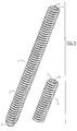
- Fig. 1 shows a side view of a worm and threaded jacket according to the present invention in a disassembled state
- the present invention which may be further understood with reference to the following description and the appended drawing, relates to devices for treating fractures and, in particular, relates to internal fixation devices for treating fractures. It is noted that, although the exemplary embodiments of the present invention are described below with respect to the treatment of fractures of the femur, the description is not meant to limit the application of the invention to such fractures as the invention may be employed in the treatment of fractures of a number of bones including, for example, the femur, humerus, tibia, ulna, radius, ankle, etc.
- embodiments of the present invention provide locking screws which substantially eliminate relative movement between an intramedullary nail and the locking screw and which, consequently, minimize relative motion between the intramedullary nail and the bone.
- Figs. 1 - 7 show an exemplary embodiment of a device of the present invention comprising an intramedullary nail 11 with a nail hole 13 that may be locked into position within a bone 14 with a two-diameter locking bolt inserted through the nail hole 13.
- the two diameter locking bolt comprises a separate male part 1 and a female part 6 that may be coupled together to function substantially as a single locking bolt.
- Fig. 1 shows a two diameter locking bolt according to the invention in a de-coupled state.
- Male part I is substantially cylindrical and extends from a proximal end 4 to a distal tip 3.
- the male part 1 has a thread 2 extending substantially helically along its entire length which preferably matches a corresponding thread formed on an internal surface of the nail hole 13 so that the male part 1 may be screwed thereinto.
- the tip 3 may be pointed or otherwise shaped to facilitate inserting the locking bolt into the nail hole 13.
- a tool receiving feature e.g., hex recess 5 is formed at the proximal end 4 for use if the male part 1 is inserted first and then, after the male part 1 is in position, the female part 6 is inserted thereover to form the 2 diameter bolt in situ.
- the female part 6 is also preferably substantially cylindrical with an outer, bone engaging thread 9 extending substantially helically along its entire length.
- a proximal end 7 of the female part 6 includes a feature for receiving a tool to be used to turn the female part 6 (e.g., hex recess 8). As would be understood by those skilled in the art, the female part 6 may be turned via this tool receiving feature to couple the female part 6 to the male part 1.
- a distal end 12 of the female part 6 includes an opening 21 to a lumen 16 including an internal thread 10 (shown in broken lines) which matches the thread 2 of the male part 1 so that the proximal end 4 may be screwed into the lumen 16 until the proximal end 4 abuts a proximal end 18 of the lumen 16.
- the diameter of the lumen 16 is preferably only slightly larger than the diameter of male part 1 so that the male part back 4 of male part 1 may be inserted into the lumen 16 of the female part 6 and the female part 6 may be screwed over the male part 1.
- the female part 6 may be screwed on male part 1 using a hex key or other tool with a hexagonal bit that fits in the hex recess 7 to drive the female part 6 while male part 1 is held in place, or by simply twisting male part 1 and/or female part 6.
- a hex key or other tool with a hexagonal bit that fits in the hex recess 7 to drive the female part 6 while male part 1 is held in place, or by simply twisting male part 1 and/or female part 6.
- any type of recess e.g., slotted, cross-point
- Fig. 2 shows the male part 1 and the female part 6 in an assembled state forming a substantially rigidly bound two-diameter bolt.
- the female part 6 is coupled to the male part 1 to create a two diameter locking bolt with an annular shoulder 19 formed by the projection of the distal end 12 of the female part 6 radially outward from the portion of the male part 1 adjacent thereto.
- the female part 6 is preferably shorter than the male part I so that a distal portion 20 of the male part 1 projects distally beyond the end 12 of the female part 6 when the male part 1 and the female part 6 are fully screwed onto one another.
- male parts 1 of varying length are preferably provided so that a user may select a male part I whose length is substantially equal to a thickness of the bone at the location of the screw hole 13 less a slight clearance for the portion of the female part 6 extending proximally beyond the proximal end 18 of the lumen 16. Then, when a female part 6 is selected having a length substantially corresponding to a distance between the near cortex 15 of the bone 14 and the close side of the nail 11, the female part 6 will screw over the male part 1 until the proximal end 7 of the female part 6 is substantially flush with the outer surface of the bone 14.
- Fig. 3 shows a cross-sectional view as well as a top view of both the male part 1 and the female part 6 in the unassembled state.
- the top view shows the hex recess 5 at the proximal end 4 of the male part 1 and the hex recess 8 at the proximal end 7 of the female part 6 while the cross section of the female part 6 shows the inner thread 10 of the lumen 16.
- the diameter of the lumen 16 is shown in broken lines on the top view of female part 6.
- Fig. 4 shows a cross sectional view of the male part 1 and the female part 6 coupled to one another with the male thread 2 engaging the thread 10 of the lumen 16 with minimal clearance therebetween when the male part 1 and the female part 6 are coupled to one another to minimize or eliminate relative movement between these parts.
- the pitch of the threading of male part 1 and the female part 6 are also shown in Fig. 5 .
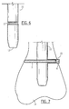
- Figs. 6 and 7 show the nail 11 that is to be stabilized by a two-diameter locking bolt according to the present invention.
- a distal tip 12 of the nail 11 is inserted into a long bone 14 such as, for example, the femur through the medullary canal such that the entire length of the nail 11 is received within the bone 14 and provides stability to a fracture (not shown).
- a hole is drilled through the bone 14 in alignment with the nail hole 13 so that a hole extends through one side of the bone cortex through the nail 11 (via hole 13) and through the opposite side of the bone cortex on the opposite side of the nail 11 to a position which may, for example, be adjacent to an outer surface of the bone 14.
- a physician or other medical professional determines the total length required for the two-diameter bolt to maximize the length of the two-diameter bolt engaging the bone 14 by measuring the distance from the hole in the bone cortex to the far end of the hole. This depth measurement is then used to select a male part 1 with a length which is approximately equal to the total length of the hole minus a thickness of the portion of the female part 6 extending proximally of the proximal end of the lumen 16 as described above. After selection of a male part 1 of the desired length, the depth gauge is used to measure the distance between the nail 13 and the opening into the hole in the near cortex of the bone 14. The user then selects a female part 6 of substantially this second length.
- the selected male part 1 and female part 6 are then coupled to one another by inserting the proximal end 4 of the male part 1 into the lumen 16 of the female part 6 so that the thread 2 of the male part 1 engages the inner thread 10 and the two components are rotated relative to one another to securely fasten them together to form a single two-diameter locking bolt.
- the two-diameter locking bolt is then inserted through the bone hole and the corresponding nail hole 13 by rotating the two-diameter bolt via the hex recess 8 (e.g., using a hex key) until the shoulder 19 abuts the outer surface of the nail 11 surrounding the hole 13.
- the proximal end 7 of the female part 6 should be substantially flush with the outer surface of the bone 14.
- engagement between the nail 11 and the two-diameter locking bolt cause the bolt and the nail 11 to operate as substantially a single mechanical unit minimizing or eliminating micro-movements therebetween.
Abstract
Description
- The present invention relates to a device for securing an intramedullary implant within a bone according to the preambule of
claim 1. - Intramedullary nails for use in the treatment of fractures of bone shafts have included holes close to ends of the nail on both sides of the fracture through which locking bolts were inserted substantially perpendicular to the nail to improve the rotational stability of the fracture and to avoid undesirable bone shortening at the fracture sile. However, movement between the nail and locking bolts may cause difficulties especially where the bone is osteoporotic or where the fracture is close to an end of the bone.
- An osteosynthetic aid for tubular bones is known from
US 2004/0147930 which includes a locking nail.US 6 355 043 B1 discloses another device according to the preamble ofclaim 1. - The present invention is directed to a device for securing an intramedullary implant within a bone, comprising a bolt having a first portion extending proximally from a distal end of the bolt and a second portion extending proximally from a proximal end of the first portion to a proximal end of the bolt, wherein a length of the bolt is selected to substantially match a thickness of a portion of bone through which it is to be inserted. A length of the second portion is selected to substantially equal a distance from a point on an outer surface of the bone through which the bolt is to be inserted into the bone to an outer surface of the implant so that, when the bolt is fully inserted into the bone, the distal end of the second portion abuts an outer surface of the implant.
- The present invention is further directed to an intramedullary osteosynthetic device for long bones fractures having improved bone holding power. In order to increase the bone holding power of the locked nails, micro-movements between the nail and locking bolts is minimized by applying compression between the nail and the locking bolts. To achieve compression between the nail and locking bolts, a multi-diameter locking bolt is inserted through a threaded nail hole. In addition, if it is desired to reduce the number of different required bolts required in inventory, a two part locking bolt including a front male part and a rear female part may be applied. The male and female parts are preferably strongly locked together to form a unit that functions substantially as a single bolt.
- After a nail or other implant has been inserted into the bone (e.g., within the medullary canal), a hole is drilled through the bone aligned with a level of a corresponding hole through the nail. A depth gauge is then used to determine a required total bolt length. The depth gauge is then used to determine a distance between the near bone cortex and the nail to determine the required length of an increased diameter portion of the bolt. Based on the total bolt length required and the required length of the increased diameter portion of the bolt, an appropriately dimensioned bolt is selected. For two part bolts, the required bolt length corresponds to the length of the male part as will be discussed in more detail below while the distance between the nail and the near bone cortex is used to select an appropriately sized female part. The appropriately sized single piece bolt is then inserted through the bone and the nail to lock the nail in the desired position and prevent undesired micro-movements thereof. For a two piece bolt, the selected male part is inserted into the selected female part and these parts are strongly fastened together to form a unit operating substantially as a single bolt -- i.e., to form a two diameter locking bolt. The two diameter locking bolt is inserted through the bone hole and through corresponding nail hole until the larger-diameter-rear-part of the two diameter locking bolt abuts the nail. The bolt is then strongly fastened to the nail to establish compression between the bolt and the nail forcing the combination of the two diameter locking bolt and the nail to operate as a single mechanical unit substantially eliminating micro-movements therebetween.
-
Fig. 1 shows a side view of a worm and threaded jacket according to the present invention in a disassembled state; -
Fig. 2 shows a side view of the threaded jacket inserted over the worm ofFig. 1 ; -
Fig. 3 shows a cross-sectional view of the worm and threaded jacket ofFig. 1 in the disassembled state; -
Fig. 4 shows a cross-sectional view of a threaded jacket inserted over the worm ofFig. 1 ; -
Fig. 5 shows a perspective view of the worm and threaded jacket ofFig. 1 ; -
Fig. 6 shows a side view of a distal end of an intramedullary nail for use in conjunction with the worm and threaded jacket ofFig. 1 ; and -
Fig. 7 shows a cross-sectional view of a bone in which the nail ofFig. 6 and the worm and threaded jacket ofFig. 1 have been inserted. - The present invention, which may be further understood with reference to the following description and the appended drawing, relates to devices for treating fractures and, in particular, relates to internal fixation devices for treating fractures. It is noted that, although the exemplary embodiments of the present invention are described below with respect to the treatment of fractures of the femur, the description is not meant to limit the application of the invention to such fractures as the invention may be employed in the treatment of fractures of a number of bones including, for example, the femur, humerus, tibia, ulna, radius, ankle, etc.
- To improve the performance of intramedullary nails in osteoporitic bones or in the case of a fracture adjacent to an end of a bone, embodiments of the present invention provide locking screws which substantially eliminate relative movement between an intramedullary nail and the locking screw and which, consequently, minimize relative motion between the intramedullary nail and the bone.
-
Figs. 1 - 7 show an exemplary embodiment of a device of the present invention comprising anintramedullary nail 11 with a nail hole 13 that may be locked into position within abone 14 with a two-diameter locking bolt inserted through the nail hole 13. As shown inFigs. 1 - 4 , the two diameter locking bolt comprises a separatemale part 1 and afemale part 6 that may be coupled together to function substantially as a single locking bolt.Fig. 1 shows a two diameter locking bolt according to the invention in a de-coupled state. Male part I is substantially cylindrical and extends from aproximal end 4 to adistal tip 3. Themale part 1 has athread 2 extending substantially helically along its entire length which preferably matches a corresponding thread formed on an internal surface of the nail hole 13 so that themale part 1 may be screwed thereinto. As would be understood by those skilled in the art, thetip 3 may be pointed or otherwise shaped to facilitate inserting the locking bolt into the nail hole 13. A tool receiving feature (e.g., hex recess 5) is formed at theproximal end 4 for use if themale part 1 is inserted first and then, after themale part 1 is in position, thefemale part 6 is inserted thereover to form the 2 diameter bolt in situ. - The
female part 6 is also preferably substantially cylindrical with an outer, boneengaging thread 9 extending substantially helically along its entire length. A proximal end 7 of thefemale part 6 includes a feature for receiving a tool to be used to turn the female part 6 (e.g., hex recess 8). As would be understood by those skilled in the art, thefemale part 6 may be turned via this tool receiving feature to couple thefemale part 6 to themale part 1. Adistal end 12 of thefemale part 6 includes an opening 21 to alumen 16 including an internal thread 10 (shown in broken lines) which matches thethread 2 of themale part 1 so that theproximal end 4 may be screwed into thelumen 16 until theproximal end 4 abuts aproximal end 18 of thelumen 16. As would be understood by those skilled in the art, the diameter of thelumen 16 is preferably only slightly larger than the diameter ofmale part 1 so that the male part back 4 ofmale part 1 may be inserted into thelumen 16 of thefemale part 6 and thefemale part 6 may be screwed over themale part 1. As indicated above, thefemale part 6 may be screwed onmale part 1 using a hex key or other tool with a hexagonal bit that fits in the hex recess 7 to drive thefemale part 6 whilemale part 1 is held in place, or by simply twistingmale part 1 and/orfemale part 6. It will be understood by those skilled in the art that any type of recess (e.g., slotted, cross-point) may be used instead of themale hex recess 5 and the female hex recess 8 to drive either of the male andfemale parts -
Fig. 2 shows themale part 1 and thefemale part 6 in an assembled state forming a substantially rigidly bound two-diameter bolt. As shown in broken lines, thefemale part 6 is coupled to themale part 1 to create a two diameter locking bolt with anannular shoulder 19 formed by the projection of thedistal end 12 of thefemale part 6 radially outward from the portion of themale part 1 adjacent thereto. Thefemale part 6 is preferably shorter than the male part I so that adistal portion 20 of themale part 1 projects distally beyond theend 12 of thefemale part 6 when themale part 1 and thefemale part 6 are fully screwed onto one another. Those skilled in the art will understand thatmale parts 1 of varying length are preferably provided so that a user may select a male part I whose length is substantially equal to a thickness of the bone at the location of the screw hole 13 less a slight clearance for the portion of thefemale part 6 extending proximally beyond theproximal end 18 of thelumen 16. Then, when afemale part 6 is selected having a length substantially corresponding to a distance between thenear cortex 15 of thebone 14 and the close side of thenail 11, thefemale part 6 will screw over themale part 1 until the proximal end 7 of thefemale part 6 is substantially flush with the outer surface of thebone 14. -
Fig. 3 shows a cross-sectional view as well as a top view of both themale part 1 and thefemale part 6 in the unassembled state. The top view shows the hex recess 5 at theproximal end 4 of themale part 1 and the hex recess 8 at the proximal end 7 of thefemale part 6 while the cross section of thefemale part 6 shows theinner thread 10 of thelumen 16. The diameter of thelumen 16 is shown in broken lines on the top view offemale part 6.Fig. 4 shows a cross sectional view of themale part 1 and thefemale part 6 coupled to one another with themale thread 2 engaging thethread 10 of thelumen 16 with minimal clearance therebetween when themale part 1 and thefemale part 6 are coupled to one another to minimize or eliminate relative movement between these parts. The pitch of the threading ofmale part 1 and thefemale part 6 are also shown inFig. 5 . -
Figs. 6 and 7 show thenail 11 that is to be stabilized by a two-diameter locking bolt according to the present invention. As understood by those skilled in the art, adistal tip 12 of thenail 11 is inserted into along bone 14 such as, for example, the femur through the medullary canal such that the entire length of thenail 11 is received within thebone 14 and provides stability to a fracture (not shown). Once inserted, a hole is drilled through thebone 14 in alignment with the nail hole 13 so that a hole extends through one side of the bone cortex through the nail 11 (via hole 13) and through the opposite side of the bone cortex on the opposite side of thenail 11 to a position which may, for example, be adjacent to an outer surface of thebone 14. Using a depth gauge, a physician or other medical professional then determines the total length required for the two-diameter bolt to maximize the length of the two-diameter bolt engaging thebone 14 by measuring the distance from the hole in the bone cortex to the far end of the hole. This depth measurement is then used to select amale part 1 with a length which is approximately equal to the total length of the hole minus a thickness of the portion of thefemale part 6 extending proximally of the proximal end of thelumen 16 as described above. After selection of amale part 1 of the desired length, the depth gauge is used to measure the distance between the nail 13 and the opening into the hole in the near cortex of thebone 14. The user then selects afemale part 6 of substantially this second length. - The selected
male part 1 andfemale part 6 are then coupled to one another by inserting theproximal end 4 of themale part 1 into thelumen 16 of thefemale part 6 so that thethread 2 of themale part 1 engages theinner thread 10 and the two components are rotated relative to one another to securely fasten them together to form a single two-diameter locking bolt. The two-diameter locking bolt is then inserted through the bone hole and the corresponding nail hole 13 by rotating the two-diameter bolt via the hex recess 8 (e.g., using a hex key) until theshoulder 19 abuts the outer surface of thenail 11 surrounding the hole 13. As would be understood by those skilled in the art, at this point, the proximal end 7 of thefemale part 6 should be substantially flush with the outer surface of thebone 14. At this point, engagement between thenail 11 and the two-diameter locking bolt cause the bolt and thenail 11 to operate as substantially a single mechanical unit minimizing or eliminating micro-movements therebetween.
Claims (9)
- A device for securing an intramedullary implant (11) within a bone (14), comprising a bolt (1;6) having a first portion extending proximally from a distal end (3) of the bolt and a second portion extending proximally from a proximal end (4) of the first portion to a proximal end (7) of the bolt (1;6), the length of the bolt being selected to substantially match a thickness of a portion of bone through which it is to be inserted and the length of the second portion being selected to substantially equal the distance from a point on an outer surface of the bone through which the bolt is to be inserted into the bone to an outer surface of the implant so that, when the bolt is fully inserted into the bone, the distal end of the second portion abuts an outer surface of the implant; and wherein the second portion of the bolt (1;6) is provided with a substantially helical exterior thread (9),
characterized in that
the bolt (1;6) comprises a first elongate member (1) including a first thread (2) extending along an exterior thereof and - as said second portion - a second elongate member (6) including a lumen (16) extending therein from an opening in a distal end thereof, the lumen (16) including a second thread (10) extending along an inner wall thereof, the first and second threads (2,10) and the diameters of the first and second members (1,6) cooperating so that a proximal portion of the first member (1) is threadably coupleable within the lumen (16), a distal portion of the first member (1) extending distally beyond a distal end of the second member (6) to form the said first portion of the bolt (1;6). - The device according to claim 1, wherein an outer diameter of the second portion exceeds an outer diameter of the first portion by a predetermined distance to form a shoulder at the distal end of the second portion.
- The device according to claim 1 or 2, wherein an outer diameter of the first portion substantially corresponds to an inner diameter of a hole in the implant through which the bolt is to be inserted.
- The device according to one of the claims 1 to 3, wherein the first and second portions are integrally formed to define a unitary two-diameter bolt.
- A kit comprising a second member (6) and several first members (1) having a different length of a device according to one of the claims 1 to 3.
- A kit according to claim 5, comprising several second members (6) having different lengths according to claim 5, of a device according to one of the claims 1 to 3.
- Assembly comprising a device according to one of the claims 1 - 4 and an intramedullary nail (11) having at least one nail hole (13) adapted to receive the bolt of claim 1.
- Assembly according to claim 7, wherein said at least one nail hole (13) is provided with an inner thread that matches the first thread (2).
- Assembly according to claim 7 or 8 for the treatment of bone fractures.
Applications Claiming Priority (2)
| Application Number | Priority Date | Filing Date | Title |
|---|---|---|---|
| US85953106P | 2006-11-17 | 2006-11-17 | |
| PCT/US2007/084663 WO2008064037A2 (en) | 2006-11-17 | 2007-11-14 | Intramedullary nail including stable locking bolts |
Publications (2)
| Publication Number | Publication Date |
|---|---|
| EP2083723A2 EP2083723A2 (en) | 2009-08-05 |
| EP2083723B1 true EP2083723B1 (en) | 2011-12-28 |
Family
ID=39430492
Family Applications (1)
| Application Number | Title | Priority Date | Filing Date |
|---|---|---|---|
| EP07854640A Not-in-force EP2083723B1 (en) | 2006-11-17 | 2007-11-14 | Intramedullary nail including stable locking bolts |
Country Status (5)
| Country | Link |
|---|---|
| US (1) | US20090326533A1 (en) |
| EP (1) | EP2083723B1 (en) |
| AT (1) | ATE538741T1 (en) |
| CA (1) | CA2667776C (en) |
| WO (1) | WO2008064037A2 (en) |
Families Citing this family (19)
| Publication number | Priority date | Publication date | Assignee | Title |
|---|---|---|---|---|
| WO2010019384A1 (en) * | 2008-08-12 | 2010-02-18 | Uso-Ck, Llc | Bone compression device and methods |
| DE102009030177B4 (en) * | 2009-06-24 | 2018-04-26 | Aesculap Ag | Medullary nail and implant for fixing a medullary nail |
| US8585744B2 (en) | 2009-07-14 | 2013-11-19 | Imds Corporation | Joint arthrodesis and arthroplasty |
| US8771272B2 (en) * | 2010-06-18 | 2014-07-08 | Kettering University | Easily implantable and stable nail-fastener for skeletal fixation and method |
| US8287540B2 (en) | 2010-06-18 | 2012-10-16 | Kettering University | Easily implantable and stable nail-fastener for skeletal fixation and method |
| DE102010048052B4 (en) * | 2010-10-12 | 2015-06-25 | Bernhard Clasbrummel | Nail screw system for osteosynthesis |
| EP2797544A4 (en) | 2011-12-30 | 2016-02-17 | Synthes Gmbh | Single patient use depth gauge |
| US9949796B2 (en) | 2011-12-30 | 2018-04-24 | DePuy Synthes Products, Inc. | Round depth gauge |
| US8832920B2 (en) * | 2012-04-17 | 2014-09-16 | Accurate Manufactured Products Group, Inc. | Standoff adaptor for a threaded hollow wall anchor |
| DE202012103384U1 (en) * | 2012-09-05 | 2012-09-24 | Signus Medizintechnik Gmbh | Pelvic ring implant |
| JP5510874B1 (en) * | 2013-03-11 | 2014-06-04 | 多摩メディカル有限会社 | Medical screw and jig for removing medical screw |
| US20140343616A1 (en) * | 2013-04-22 | 2014-11-20 | Daniel Sellers | Arthrodesis compression device |
| EP3102130B1 (en) * | 2014-02-06 | 2018-04-04 | Ignite-concepts GmbH | Bone screw assembly |
| CN104173099A (en) * | 2014-08-29 | 2014-12-03 | 南华大学 | Locking screw of minimally invasive lumbosacral vertebrae locking axial fusion internal fixation system |
| EP3678565A4 (en) | 2017-09-05 | 2021-10-27 | ExsoMed Corporation | Intramedullary threaded nail for radial cortical fixation |
| EP4321117A2 (en) | 2017-10-09 | 2024-02-14 | Acumed LLC | System for bone fixation using a nail locked to an encircling anchor |
| CN109171921B (en) * | 2018-10-16 | 2021-02-09 | 北京航空航天大学 | Novel design and manufacture of bone nail easy to screw in |
| US11202663B2 (en) | 2019-02-13 | 2021-12-21 | Globus Medical, Inc. | Proximal humeral stabilization systems and methods thereof |
| US11350976B2 (en) * | 2019-11-06 | 2022-06-07 | DePuy Synthes Products, Inc. | System and method for treating a bone |
Family Cites Families (13)
| Publication number | Priority date | Publication date | Assignee | Title |
|---|---|---|---|---|
| DE2246274A1 (en) * | 1972-09-21 | 1974-03-28 | Ortopedia Gmbh | DEVICE FOR TREATMENT OF BROKEN TUBE BONES BY AXIAL PRESSURE OSTEOSYNTHESIS |
| FR2698261B1 (en) * | 1992-11-24 | 1995-03-17 | Lacaffiniere Jean Yves De | Device for guiding a double screw of the neck of the femur for locked trochantero-diaphyseal nail. |
| DE9417104U1 (en) * | 1994-10-13 | 1995-01-05 | Pennig Dietmar | Screw to fix a medullary nail |
| US5779704A (en) * | 1996-03-19 | 1998-07-14 | Kim; Andrew C. | Bi-directional universal dynamic compression device |
| US6355043B1 (en) * | 1999-03-01 | 2002-03-12 | Sulzer Orthopedics Ltd. | Bone screw for anchoring a marrow nail |
| FR2799115B1 (en) * | 1999-10-01 | 2003-02-21 | Jean Claude Bouvet | MODULAR ROD FOR HIP PROSTHESIS |
| US6235031B1 (en) * | 2000-02-04 | 2001-05-22 | Encore Medical Corporation | Intramedullary fracture fixation device |
| US6524314B1 (en) * | 2001-08-24 | 2003-02-25 | John C. Dean | Interlocking intramedullary nail |
| US6981976B1 (en) * | 2002-05-13 | 2006-01-03 | Biomet, Inc. | Method and apparatus for inserting and countersinking a modular screw |
| DE20219683U1 (en) * | 2002-12-19 | 2004-04-29 | Stryker Trauma Gmbh | osteosynthesis |
| WO2004069031A2 (en) * | 2003-02-03 | 2004-08-19 | Kinetikos Medical Incorporated | Compression screw apparatuses, systems and methods |
| US7044953B2 (en) * | 2003-02-27 | 2006-05-16 | Stryker Leibinger Gmbh & Co. Kg | Compression bone screw |
| US20050075637A1 (en) * | 2003-04-04 | 2005-04-07 | Semet Elliot Charles | Interlocking IM nails with outer screw |
-
2007
- 2007-11-14 EP EP07854640A patent/EP2083723B1/en not_active Not-in-force
- 2007-11-14 AT AT07854640T patent/ATE538741T1/en active
- 2007-11-14 WO PCT/US2007/084663 patent/WO2008064037A2/en active Application Filing
- 2007-11-14 US US12/439,088 patent/US20090326533A1/en not_active Abandoned
- 2007-11-14 CA CA2667776A patent/CA2667776C/en not_active Expired - Fee Related
Also Published As
| Publication number | Publication date |
|---|---|
| US20090326533A1 (en) | 2009-12-31 |
| CA2667776C (en) | 2015-01-20 |
| CA2667776A1 (en) | 2008-05-29 |
| WO2008064037A3 (en) | 2008-08-07 |
| ATE538741T1 (en) | 2012-01-15 |
| WO2008064037A2 (en) | 2008-05-29 |
| EP2083723A2 (en) | 2009-08-05 |
Similar Documents
| Publication | Publication Date | Title |
|---|---|---|
| EP2083723B1 (en) | Intramedullary nail including stable locking bolts | |
| US7582107B2 (en) | Compression screw apparatuses, systems and methods | |
| EP0550814B1 (en) | Anchorage nail for the treatment of hollow bone fractures | |
| US8454606B2 (en) | Device for the treatment of fractures of the femur | |
| US6302887B1 (en) | Hardware for high strength fastening of bone | |
| US10335214B2 (en) | Multiplexed screws | |
| US6123708A (en) | Intramedullary bone fixation rod | |
| CA2649444C (en) | Hip helical implant | |
| US7780667B2 (en) | Orthopaedic plate and screw assembly | |
| JP4978906B2 (en) | Fracture fixation device for femoral trochanteric fracture | |
| CA2206764C (en) | Implant inserting device | |
| AU670456B2 (en) | Osteosynthesis device | |
| US6648889B2 (en) | Intramedullary hip nail with bifurcated lock | |
| US9433449B2 (en) | Intramedullary nail system including tang-deployment screw with male interface | |
| US5690633A (en) | Orthopedic fracture fixation device | |
| US6524314B1 (en) | Interlocking intramedullary nail | |
| EP1691700B1 (en) | Humeral nail with insert for fixing a screw | |
| US20080140077A1 (en) | Femoral Universal Nail | |
| US20050010223A1 (en) | Intramedullary nail system and method for fixation of a fractured bone | |
| US20070270847A1 (en) | Locking compression hip screw | |
| US20070270845A1 (en) | Orthopaedic plate and screw assembly | |
| US20120109127A1 (en) | Intramedullary Nail | |
| WO2011006413A1 (en) | Intramedullary nail fixing device for proximal femoral fracture | |
| US20100211073A1 (en) | Intramedullary compression rod | |
| CN209172478U (en) | Arthroscopic surface helix locking structure |
Legal Events
| Date | Code | Title | Description |
|---|---|---|---|
| PUAI | Public reference made under article 153(3) epc to a published international application that has entered the european phase |
Free format text: ORIGINAL CODE: 0009012 |
|
| 17P | Request for examination filed |
Effective date: 20090429 |
|
| AK | Designated contracting states |
Kind code of ref document: A2 Designated state(s): AT BE BG CH CY CZ DE DK EE ES FI FR GB GR HU IE IS IT LI LT LU LV MC MT NL PL PT RO SE SI SK TR |
|
| DAX | Request for extension of the european patent (deleted) | ||
| 17Q | First examination report despatched |
Effective date: 20100917 |
|
| GRAP | Despatch of communication of intention to grant a patent |
Free format text: ORIGINAL CODE: EPIDOSNIGR1 |
|
| GRAS | Grant fee paid |
Free format text: ORIGINAL CODE: EPIDOSNIGR3 |
|
| GRAA | (expected) grant |
Free format text: ORIGINAL CODE: 0009210 |
|
| STAA | Information on the status of an ep patent application or granted ep patent |
Free format text: STATUS: THE PATENT HAS BEEN GRANTED |
|
| AK | Designated contracting states |
Kind code of ref document: B1 Designated state(s): AT BE BG CH CY CZ DE DK EE ES FI FR GB GR HU IE IS IT LI LT LU LV MC MT NL PL PT RO SE SI SK TR |
|
| REG | Reference to a national code |
Ref country code: GB Ref legal event code: FG4D |
|
| REG | Reference to a national code |
Ref country code: CH Ref legal event code: NV Representative=s name: DR. LUSUARDI AG Ref country code: CH Ref legal event code: EP |
|
| REG | Reference to a national code |
Ref country code: AT Ref legal event code: REF Ref document number: 538741 Country of ref document: AT Kind code of ref document: T Effective date: 20120115 |
|
| REG | Reference to a national code |
Ref country code: IE Ref legal event code: FG4D |
|
| REG | Reference to a national code |
Ref country code: DE Ref legal event code: R096 Ref document number: 602007019750 Country of ref document: DE Effective date: 20120308 |
|
| REG | Reference to a national code |
Ref country code: NL Ref legal event code: VDEP Effective date: 20111228 |
|
| PG25 | Lapsed in a contracting state [announced via postgrant information from national office to epo] |
Ref country code: LT Free format text: LAPSE BECAUSE OF FAILURE TO SUBMIT A TRANSLATION OF THE DESCRIPTION OR TO PAY THE FEE WITHIN THE PRESCRIBED TIME-LIMIT Effective date: 20111228 |
|
| LTIE | Lt: invalidation of european patent or patent extension |
Effective date: 20111228 |
|
| PG25 | Lapsed in a contracting state [announced via postgrant information from national office to epo] |
Ref country code: LV Free format text: LAPSE BECAUSE OF FAILURE TO SUBMIT A TRANSLATION OF THE DESCRIPTION OR TO PAY THE FEE WITHIN THE PRESCRIBED TIME-LIMIT Effective date: 20111228 Ref country code: SI Free format text: LAPSE BECAUSE OF FAILURE TO SUBMIT A TRANSLATION OF THE DESCRIPTION OR TO PAY THE FEE WITHIN THE PRESCRIBED TIME-LIMIT Effective date: 20111228 Ref country code: SE Free format text: LAPSE BECAUSE OF FAILURE TO SUBMIT A TRANSLATION OF THE DESCRIPTION OR TO PAY THE FEE WITHIN THE PRESCRIBED TIME-LIMIT Effective date: 20111228 Ref country code: GR Free format text: LAPSE BECAUSE OF FAILURE TO SUBMIT A TRANSLATION OF THE DESCRIPTION OR TO PAY THE FEE WITHIN THE PRESCRIBED TIME-LIMIT Effective date: 20120329 |
|
| PG25 | Lapsed in a contracting state [announced via postgrant information from national office to epo] |
Ref country code: CY Free format text: LAPSE BECAUSE OF FAILURE TO SUBMIT A TRANSLATION OF THE DESCRIPTION OR TO PAY THE FEE WITHIN THE PRESCRIBED TIME-LIMIT Effective date: 20111228 Ref country code: BE Free format text: LAPSE BECAUSE OF FAILURE TO SUBMIT A TRANSLATION OF THE DESCRIPTION OR TO PAY THE FEE WITHIN THE PRESCRIBED TIME-LIMIT Effective date: 20111228 |
|
| PG25 | Lapsed in a contracting state [announced via postgrant information from national office to epo] |
Ref country code: EE Free format text: LAPSE BECAUSE OF FAILURE TO SUBMIT A TRANSLATION OF THE DESCRIPTION OR TO PAY THE FEE WITHIN THE PRESCRIBED TIME-LIMIT Effective date: 20111228 Ref country code: IS Free format text: LAPSE BECAUSE OF FAILURE TO SUBMIT A TRANSLATION OF THE DESCRIPTION OR TO PAY THE FEE WITHIN THE PRESCRIBED TIME-LIMIT Effective date: 20120428 Ref country code: CZ Free format text: LAPSE BECAUSE OF FAILURE TO SUBMIT A TRANSLATION OF THE DESCRIPTION OR TO PAY THE FEE WITHIN THE PRESCRIBED TIME-LIMIT Effective date: 20111228 Ref country code: BG Free format text: LAPSE BECAUSE OF FAILURE TO SUBMIT A TRANSLATION OF THE DESCRIPTION OR TO PAY THE FEE WITHIN THE PRESCRIBED TIME-LIMIT Effective date: 20120328 Ref country code: NL Free format text: LAPSE BECAUSE OF FAILURE TO SUBMIT A TRANSLATION OF THE DESCRIPTION OR TO PAY THE FEE WITHIN THE PRESCRIBED TIME-LIMIT Effective date: 20111228 Ref country code: SK Free format text: LAPSE BECAUSE OF FAILURE TO SUBMIT A TRANSLATION OF THE DESCRIPTION OR TO PAY THE FEE WITHIN THE PRESCRIBED TIME-LIMIT Effective date: 20111228 |
|
| PG25 | Lapsed in a contracting state [announced via postgrant information from national office to epo] |
Ref country code: PT Free format text: LAPSE BECAUSE OF FAILURE TO SUBMIT A TRANSLATION OF THE DESCRIPTION OR TO PAY THE FEE WITHIN THE PRESCRIBED TIME-LIMIT Effective date: 20120430 Ref country code: RO Free format text: LAPSE BECAUSE OF FAILURE TO SUBMIT A TRANSLATION OF THE DESCRIPTION OR TO PAY THE FEE WITHIN THE PRESCRIBED TIME-LIMIT Effective date: 20111228 Ref country code: PL Free format text: LAPSE BECAUSE OF FAILURE TO SUBMIT A TRANSLATION OF THE DESCRIPTION OR TO PAY THE FEE WITHIN THE PRESCRIBED TIME-LIMIT Effective date: 20111228 |
|
| REG | Reference to a national code |
Ref country code: AT Ref legal event code: MK05 Ref document number: 538741 Country of ref document: AT Kind code of ref document: T Effective date: 20111228 |
|
| PLBI | Opposition filed |
Free format text: ORIGINAL CODE: 0009260 |
|
| PG25 | Lapsed in a contracting state [announced via postgrant information from national office to epo] |
Ref country code: DK Free format text: LAPSE BECAUSE OF FAILURE TO SUBMIT A TRANSLATION OF THE DESCRIPTION OR TO PAY THE FEE WITHIN THE PRESCRIBED TIME-LIMIT Effective date: 20111228 |
|
| PLAX | Notice of opposition and request to file observation + time limit sent |
Free format text: ORIGINAL CODE: EPIDOSNOBS2 |
|
| 26 | Opposition filed |
Opponent name: DMV MARKETING+VERTRIEBS GMBH Effective date: 20120928 |
|
| REG | Reference to a national code |
Ref country code: DE Ref legal event code: R026 Ref document number: 602007019750 Country of ref document: DE Effective date: 20120928 |
|
| PG25 | Lapsed in a contracting state [announced via postgrant information from national office to epo] |
Ref country code: AT Free format text: LAPSE BECAUSE OF FAILURE TO SUBMIT A TRANSLATION OF THE DESCRIPTION OR TO PAY THE FEE WITHIN THE PRESCRIBED TIME-LIMIT Effective date: 20111228 |
|
| PLBB | Reply of patent proprietor to notice(s) of opposition received |
Free format text: ORIGINAL CODE: EPIDOSNOBS3 |
|
| PG25 | Lapsed in a contracting state [announced via postgrant information from national office to epo] |
Ref country code: ES Free format text: LAPSE BECAUSE OF FAILURE TO SUBMIT A TRANSLATION OF THE DESCRIPTION OR TO PAY THE FEE WITHIN THE PRESCRIBED TIME-LIMIT Effective date: 20120408 |
|
| PG25 | Lapsed in a contracting state [announced via postgrant information from national office to epo] |
Ref country code: FI Free format text: LAPSE BECAUSE OF FAILURE TO SUBMIT A TRANSLATION OF THE DESCRIPTION OR TO PAY THE FEE WITHIN THE PRESCRIBED TIME-LIMIT Effective date: 20111228 |
|
| REG | Reference to a national code |
Ref country code: IE Ref legal event code: MM4A |
|
| PLCK | Communication despatched that opposition was rejected |
Free format text: ORIGINAL CODE: EPIDOSNREJ1 |
|
| PG25 | Lapsed in a contracting state [announced via postgrant information from national office to epo] |
Ref country code: IE Free format text: LAPSE BECAUSE OF NON-PAYMENT OF DUE FEES Effective date: 20121114 |
|
| PG25 | Lapsed in a contracting state [announced via postgrant information from national office to epo] |
Ref country code: MT Free format text: LAPSE BECAUSE OF FAILURE TO SUBMIT A TRANSLATION OF THE DESCRIPTION OR TO PAY THE FEE WITHIN THE PRESCRIBED TIME-LIMIT Effective date: 20111228 |
|
| APBM | Appeal reference recorded |
Free format text: ORIGINAL CODE: EPIDOSNREFNO |
|
| APBP | Date of receipt of notice of appeal recorded |
Free format text: ORIGINAL CODE: EPIDOSNNOA2O |
|
| APAH | Appeal reference modified |
Free format text: ORIGINAL CODE: EPIDOSCREFNO |
|
| APBQ | Date of receipt of statement of grounds of appeal recorded |
Free format text: ORIGINAL CODE: EPIDOSNNOA3O |
|
| PG25 | Lapsed in a contracting state [announced via postgrant information from national office to epo] |
Ref country code: TR Free format text: LAPSE BECAUSE OF FAILURE TO SUBMIT A TRANSLATION OF THE DESCRIPTION OR TO PAY THE FEE WITHIN THE PRESCRIBED TIME-LIMIT Effective date: 20111228 Ref country code: MC Free format text: LAPSE BECAUSE OF NON-PAYMENT OF DUE FEES Effective date: 20121130 |
|
| PG25 | Lapsed in a contracting state [announced via postgrant information from national office to epo] |
Ref country code: LU Free format text: LAPSE BECAUSE OF NON-PAYMENT OF DUE FEES Effective date: 20121114 |
|
| PG25 | Lapsed in a contracting state [announced via postgrant information from national office to epo] |
Ref country code: HU Free format text: LAPSE BECAUSE OF FAILURE TO SUBMIT A TRANSLATION OF THE DESCRIPTION OR TO PAY THE FEE WITHIN THE PRESCRIBED TIME-LIMIT Effective date: 20071114 |
|
| APBY | Invitation to file observations in appeal sent |
Free format text: ORIGINAL CODE: EPIDOSNOBA2O |
|
| APCA | Receipt of observations in appeal recorded |
Free format text: ORIGINAL CODE: EPIDOSNOBA4O |
|
| APBU | Appeal procedure closed |
Free format text: ORIGINAL CODE: EPIDOSNNOA9O |
|
| REG | Reference to a national code |
Ref country code: FR Ref legal event code: PLFP Year of fee payment: 10 |
|
| PLAY | Examination report in opposition despatched + time limit |
Free format text: ORIGINAL CODE: EPIDOSNORE2 |
|
| PLBC | Reply to examination report in opposition received |
Free format text: ORIGINAL CODE: EPIDOSNORE3 |
|
| REG | Reference to a national code |
Ref country code: DE Ref legal event code: R100 Ref document number: 602007019750 Country of ref document: DE |
|
| PLAG | Information modified related to despatch of communication that opposition is rejected |
Free format text: ORIGINAL CODE: EPIDOSCREJ1 |
|
| STAA | Information on the status of an ep patent application or granted ep patent |
Free format text: STATUS: THE PATENT HAS BEEN GRANTED |
|
| REG | Reference to a national code |
Ref country code: FR Ref legal event code: PLFP Year of fee payment: 11 |
|
| REG | Reference to a national code |
Ref country code: FR Ref legal event code: PLFP Year of fee payment: 12 |
|
| PGFP | Annual fee paid to national office [announced via postgrant information from national office to epo] |
Ref country code: DE Payment date: 20191029 Year of fee payment: 13 |
|
| PGFP | Annual fee paid to national office [announced via postgrant information from national office to epo] |
Ref country code: IT Payment date: 20191108 Year of fee payment: 13 Ref country code: FR Payment date: 20191014 Year of fee payment: 13 |
|
| PGFP | Annual fee paid to national office [announced via postgrant information from national office to epo] |
Ref country code: GB Payment date: 20191115 Year of fee payment: 13 |
|
| REG | Reference to a national code |
Ref country code: DE Ref legal event code: R119 Ref document number: 602007019750 Country of ref document: DE |
|
| GBPC | Gb: european patent ceased through non-payment of renewal fee |
Effective date: 20201114 |
|
| PG25 | Lapsed in a contracting state [announced via postgrant information from national office to epo] |
Ref country code: FR Free format text: LAPSE BECAUSE OF NON-PAYMENT OF DUE FEES Effective date: 20201130 Ref country code: IT Free format text: LAPSE BECAUSE OF NON-PAYMENT OF DUE FEES Effective date: 20201114 |
|
| PG25 | Lapsed in a contracting state [announced via postgrant information from national office to epo] |
Ref country code: GB Free format text: LAPSE BECAUSE OF NON-PAYMENT OF DUE FEES Effective date: 20201114 Ref country code: DE Free format text: LAPSE BECAUSE OF NON-PAYMENT OF DUE FEES Effective date: 20210601 |
|
| PGFP | Annual fee paid to national office [announced via postgrant information from national office to epo] |
Ref country code: CH Payment date: 20211014 Year of fee payment: 15 |
|
| PLBN | Opposition rejected |
Free format text: ORIGINAL CODE: 0009273 |
|
| STAA | Information on the status of an ep patent application or granted ep patent |
Free format text: STATUS: OPPOSITION REJECTED |
|
| 27O | Opposition rejected |
Effective date: 20170523 |
|
| REG | Reference to a national code |
Ref country code: CH Ref legal event code: PL |
|
| PG25 | Lapsed in a contracting state [announced via postgrant information from national office to epo] |
Ref country code: LI Free format text: LAPSE BECAUSE OF NON-PAYMENT OF DUE FEES Effective date: 20221130 Ref country code: CH Free format text: LAPSE BECAUSE OF NON-PAYMENT OF DUE FEES Effective date: 20221130 |