EP2083664B1 - Mixing tool - Google Patents
Mixing tool Download PDFInfo
- Publication number
- EP2083664B1 EP2083664B1 EP07826582A EP07826582A EP2083664B1 EP 2083664 B1 EP2083664 B1 EP 2083664B1 EP 07826582 A EP07826582 A EP 07826582A EP 07826582 A EP07826582 A EP 07826582A EP 2083664 B1 EP2083664 B1 EP 2083664B1
- Authority
- EP
- European Patent Office
- Prior art keywords
- mixer according
- container
- support seat
- rotation
- rod
- Prior art date
- Legal status (The legal status is an assumption and is not a legal conclusion. Google has not performed a legal analysis and makes no representation as to the accuracy of the status listed.)
- Not-in-force
Links
- 238000010411 cooking Methods 0.000 claims description 5
- 239000000463 material Substances 0.000 claims description 3
- 238000010438 heat treatment Methods 0.000 claims description 2
- 230000002093 peripheral effect Effects 0.000 claims description 2
- 230000033001 locomotion Effects 0.000 description 7
- 239000000203 mixture Substances 0.000 description 7
- 239000004615 ingredient Substances 0.000 description 5
- 238000004140 cleaning Methods 0.000 description 1
- 230000001419 dependent effect Effects 0.000 description 1
- 238000005485 electric heating Methods 0.000 description 1
- 239000008240 homogeneous mixture Substances 0.000 description 1
- 238000012423 maintenance Methods 0.000 description 1
- 230000001681 protective effect Effects 0.000 description 1
- 230000000284 resting effect Effects 0.000 description 1
Images

Classifications
-
- A—HUMAN NECESSITIES
- A47—FURNITURE; DOMESTIC ARTICLES OR APPLIANCES; COFFEE MILLS; SPICE MILLS; SUCTION CLEANERS IN GENERAL
- A47J—KITCHEN EQUIPMENT; COFFEE MILLS; SPICE MILLS; APPARATUS FOR MAKING BEVERAGES
- A47J43/00—Implements for preparing or holding food, not provided for in other groups of this subclass
- A47J43/04—Machines for domestic use not covered elsewhere, e.g. for grinding, mixing, stirring, kneading, emulsifying, whipping or beating foodstuffs, e.g. power-driven
- A47J43/07—Parts or details, e.g. mixing tools, whipping tools
- A47J43/0705—Parts or details, e.g. mixing tools, whipping tools for machines with tools driven from the upper side
- A47J43/0711—Parts or details, e.g. mixing tools, whipping tools for machines with tools driven from the upper side mixing, whipping or cutting tools
-
- A—HUMAN NECESSITIES
- A47—FURNITURE; DOMESTIC ARTICLES OR APPLIANCES; COFFEE MILLS; SPICE MILLS; SUCTION CLEANERS IN GENERAL
- A47J—KITCHEN EQUIPMENT; COFFEE MILLS; SPICE MILLS; APPARATUS FOR MAKING BEVERAGES
- A47J27/00—Cooking-vessels
- A47J27/004—Cooking-vessels with integral electrical heating means
-
- A—HUMAN NECESSITIES
- A47—FURNITURE; DOMESTIC ARTICLES OR APPLIANCES; COFFEE MILLS; SPICE MILLS; SUCTION CLEANERS IN GENERAL
- A47J—KITCHEN EQUIPMENT; COFFEE MILLS; SPICE MILLS; APPARATUS FOR MAKING BEVERAGES
- A47J43/00—Implements for preparing or holding food, not provided for in other groups of this subclass
- A47J43/04—Machines for domestic use not covered elsewhere, e.g. for grinding, mixing, stirring, kneading, emulsifying, whipping or beating foodstuffs, e.g. power-driven
- A47J43/07—Parts or details, e.g. mixing tools, whipping tools
- A47J43/08—Driving mechanisms
- A47J43/082—Driving mechanisms for machines with tools driven from the upper side
Definitions
- the present invention relates to a mixing tool used in a kitchen to mix ingredients needed for making mixtures or the like and during the cooking of dishes requiring continuous mixing.
- suchlike tools are already known, and mostly based on a common principle. I.e., they are equipped with a main body and one or two beaters set in rotation by an electric motor.
- This implementation principle is used both in simpler tools, which are held and then supported by a user with the beaters immersed in a container holding the ingredients to be mixed, and in more complex products, in which the mixer is fastened to a support base so as to keep it in position with respect to the container.
- object of the present invention is to solve said problems of the known art, by providing an electric mixer as defined in independent claim 1.
- the main advantage of the tool according to the present invention lies in the fact that it ensures a high homogeneity of the mixture to be mixed, thanks to a particular moving mechanism of the mixing tool. Moreover, the mixing tool is made so as to also ensure that all the product in the container, even that adhering to the bottom thereof, be evenly mixed and kneaded.
- the present invention is aimed at a mixer I used in a kitchen to mix ingredients needed for making mixtures or the like in a container 2 and/or during the cooking of dishes requiring continuous mixing.
- the mixer 1 comprises at least one mixing tool 5 that is set in rotation and, during use, is partially immersed in the container 2 holding the ingredients to be mixed.
- the mixing tool is implemented by a beater; however, evidently other typologies of means suitable therefor could be used, such as Archimedean screw or other spiral-shaped tools.
- the mixer 1 is made up of a main body 11 comprising positioning means 4 apt to cooperate with a rim of the container 2, in order to keep the mixer 1 in an operative position, with the beater 5 correctly positioned with respect to the container itself.
- the beater 5 comprises a rod 7 for connecting to the body of the mixer 1.
- the mixer 1 provides a rotation ring nut 9 having a seat apt to receive a free end of the rod 7.
- the mixer comprises means for setting in rotation the ring nut 9 and therefore the beater.
- the mixer 1 is preferably of electric type, equipped with controls 3 for turning on/off and/or adjusting the speed of rotation of an electric motor (not shown in the figures).
- the seat receiving the rod 7 is made so that the rod, once inserted, be tilted with respect to the axis of rotation of the ring nut 9 itself.
- said seat is obtained in correspondence of the external peripheral edge of the ring nut 9 and its longitudinal direction is tilted with respect to the axis of rotation of the ring nut 9.
- the rod 7 can freely slide in a longitudinal direction, within predetermined limits, into the seat receiving it.
- holding means is provided apt to prevent the unintentional drawing of the rod off its seat during tool use.
- such means e.g. of release type or the like, do not prevent an intentional drawing of the rod for usual cleaning and/or maintenance operations.
- a thrust spring may be provided, continuously forcing the rod 7 towards the outside of the seat itself.
- the beater 5 further comprises a substantially strip-like and spiral-shaped mixing section 6.
- This section 6 ends in a disc-shaped sliding member 8.
- a sliding member 8 is made of a material with low friction coefficient, or at least coated with such a material, because, as better explained hereinafter, it is intended to slide on the internal wall of the container 2.
- the sliding member 8 is connected to the section 6 by means of a ball joint, allowing to arrange the sliding member according to any one orientation with respect to the section 6.
- the beater 5 rotates on a longitudinal axis corresponding to the section of rod 7.
- the beater overall describes a cone in space, having the vertex in correspondence of the ring nut.
- the sliding member 8 rests on the internal wall of the container 2 and, thanks to the option of the rod 7 to slide longitudinally inside of its seat, remains adhering thereto during all the rotation of the beater 5.
- the mixer according to the present invention together with a container of specific shape.
- the container 2 should have a substantially spherical or anyhow curved (elliptical or the like) bottom region, having an average radius of curvature not exceedingly reduced.
- the specific option of motion of the beater 5, linked to the option of sliding in a longitudinal direction within the support seat in the ring nut 9, as well as to the tilted arrangement with respect to the ring nut itself, allows the beater to describe a very wide path, substantially describing a cone with the vertex in correspondence of the ring nut.
- the sliding member 8 is always in contact with the internal surface of the container and, at any variation of the radius of curvature, the longitudinal sliding within the seat of the ring nut allows the beater 5 to continue following its own path, retracting or extending from the seat in which it is housed.
- the beater according to the present invention covers a very wide volume with respect to known beaters, which merely rotate on a vertical axis with respect to the tool itself.
- the mixer according to the present invention may be conveniently used also for food cooking requiring continuous mixing.
- the container 2 may have a bottom 21 inside which it is located an electric heating element or other heating means, not illustrated in figure, allowing food cooking.
- the mixer may also have positioning means 4 such as to allow the fastening thereof to conventional pots and containers, optionally also of a shape different from the spherical one.
- the beater will cover a more limited volume with respect to the use in a spherical-shaped container, though keeping unaltered the feature of contacting the container bottom.
Landscapes
- Engineering & Computer Science (AREA)
- Food Science & Technology (AREA)
- Mechanical Engineering (AREA)
- Food-Manufacturing Devices (AREA)
- Mixers Of The Rotary Stirring Type (AREA)
- Orthopedics, Nursing, And Contraception (AREA)
- Auxiliary Devices For Machine Tools (AREA)
- Finish Polishing, Edge Sharpening, And Grinding By Specific Grinding Devices (AREA)
- Disintegrating Or Milling (AREA)
Abstract
Description
- The present invention relates to a mixing tool used in a kitchen to mix ingredients needed for making mixtures or the like and during the cooking of dishes requiring continuous mixing.
- As it is known, suchlike tools are already known, and mostly based on a common principle. I.e., they are equipped with a main body and one or two beaters set in rotation by an electric motor.
- This implementation principle is used both in simpler tools, which are held and then supported by a user with the beaters immersed in a container holding the ingredients to be mixed, and in more complex products, in which the mixer is fastened to a support base so as to keep it in position with respect to the container.
- However, both configurations entail some drawbacks. First of all, in hand mixers, the tool has to be hand-held, with the entailed tiring. Moreover, in order to obtain a homogeneous mixture the user is forced to make rotary motions, as otherwise, by keeping the beaters stationary always in the same position, no homogeneous and well-amalgamated mixture would be obtained.
- Moreover, a further drawback lies in that no known tool allows to easily and simply mix also those product parts unavoidably adhering to the container bottom. In order to do this, it is always necessary to use other collecting instruments to amalgamate the mixture, or frequently bring the beaters into contact with the container, risking however to damage both.
- A few of these drawbacks have been partly overcome by tools that do not need to be held by the user, in which, as mentioned in the foregoing, the mixer may be "resting" on the rim of a container made for this purpose, so as to have the beaters immersed in the container itself.
- However, this typology of tools does not solve the problem of mixture homogeneity, as the beaters are anyhow always stationary in the same position with respect to the container, and generally do not touch the container bottom. To avoid this problem, tools are known in which the container and the mixer are mutually rotating and arranged on different axes. Mixer of this kind are described, e.g., in the European patent
EP0570758 , inUS 3315947 , inDE 4033020 , or in the international applicationWO0130221 - These features allow to cover with the beater motion a rather wide surface, yet still insufficient to ensure a perfect mixing of all the product in the container, in particular when said product is rather thick and possilbly adhering to the bottom of the container. Hence, object of the present invention is to solve said problems of the known art, by providing an electric mixer as defined in
independent claim 1. - Secondary features of the present invention arc set forth in the corresponding dependent claims thereof.
- The main advantage of the tool according to the present invention lies in the fact that it ensures a high homogeneity of the mixture to be mixed, thanks to a particular moving mechanism of the mixing tool. Moreover, the mixing tool is made so as to also ensure that all the product in the container, even that adhering to the bottom thereof, be evenly mixed and kneaded.
- Further advantages, as well as the features and the operation modes of the present invention, will be made apparent in the following detailed description of a preferred embodiment thereof, given by way of example and not for limitative purposes, making reference to the figures of the annexed drawings, wherein:
-
Figure 1 is a perspective view of the tool according to the present invention during use; -
Figure 2 is a detail ofFigure 1 ; -
Figure 3 is a partially sectional bottom perspective view, illustrating the motion of a mixing tool; -
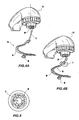
Figures 4A and 4B illustrate one option of motion of the mixing tool; andFigure 5 is a bottom view of a rotation ring nut. - Hereinafter in the present invention, reference will be made to the above-indicated figures.
- Referring initially to
Figure 1 , the present invention is aimed at a mixer I used in a kitchen to mix ingredients needed for making mixtures or the like in a container 2 and/or during the cooking of dishes requiring continuous mixing. - The
mixer 1 comprises at least onemixing tool 5 that is set in rotation and, during use, is partially immersed in the container 2 holding the ingredients to be mixed. - In the present embodiment the mixing tool is implemented by a beater; however, evidently other typologies of means suitable therefor could be used, such as Archimedean screw or other spiral-shaped tools.
- Advantageously, the
mixer 1 is made up of amain body 11 comprising positioning means 4 apt to cooperate with a rim of the container 2, in order to keep themixer 1 in an operative position, with thebeater 5 correctly positioned with respect to the container itself. - The
beater 5 comprises arod 7 for connecting to the body of themixer 1. - The
mixer 1 provides arotation ring nut 9 having a seat apt to receive a free end of therod 7. - The mixer comprises means for setting in rotation the
ring nut 9 and therefore the beater. In particular, themixer 1 is preferably of electric type, equipped withcontrols 3 for turning on/off and/or adjusting the speed of rotation of an electric motor (not shown in the figures). - It is also evident that the rotary motion of the beater may be implemented with other equivalent rotation means 9, not illustrated in greater detail as within the reach of a person skilled in the art.
- The seat receiving the
rod 7 is made so that the rod, once inserted, be tilted with respect to the axis of rotation of thering nut 9 itself. In particular, said seat is obtained in correspondence of the external peripheral edge of thering nut 9 and its longitudinal direction is tilted with respect to the axis of rotation of thering nut 9. - Owing to reasons that will be clearer hereinafter in the description, the
rod 7 can freely slide in a longitudinal direction, within predetermined limits, into the seat receiving it. Preferably, holding means is provided apt to prevent the unintentional drawing of the rod off its seat during tool use. Of course, such means, e.g. of release type or the like, do not prevent an intentional drawing of the rod for usual cleaning and/or maintenance operations. - Moreover, inside the seat a thrust spring may be provided, continuously forcing the
rod 7 towards the outside of the seat itself. - The
beater 5 further comprises a substantially strip-like and spiral-shaped mixing section 6. Thissection 6 ends in a disc-shaped slidingmember 8. Preferably, such a slidingmember 8 is made of a material with low friction coefficient, or at least coated with such a material, because, as better explained hereinafter, it is intended to slide on the internal wall of the container 2. - Always according to a preferred embodiment, the sliding
member 8 is connected to thesection 6 by means of a ball joint, allowing to arrange the sliding member according to any one orientation with respect to thesection 6. - As it may be seen in
Figure 3 , during use thebeater 5 in its motion follows a complex path. - First of all, the
beater 5 rotates on a longitudinal axis corresponding to the section ofrod 7. - Moreover, thanks to the tilt of the
rod 7 with respect to the axis of rotation of thering nut 9, the beater overall describes a cone in space, having the vertex in correspondence of the ring nut. - The sliding
member 8 rests on the internal wall of the container 2 and, thanks to the option of therod 7 to slide longitudinally inside of its seat, remains adhering thereto during all the rotation of thebeater 5. - For a greater effectiveness of operation, it is preferable to use the mixer according to the present invention together with a container of specific shape. In particular, the container 2 should have a substantially spherical or anyhow curved (elliptical or the like) bottom region, having an average radius of curvature not exceedingly reduced.
- The specific option of motion of the
beater 5, linked to the option of sliding in a longitudinal direction within the support seat in thering nut 9, as well as to the tilted arrangement with respect to the ring nut itself, allows the beater to describe a very wide path, substantially describing a cone with the vertex in correspondence of the ring nut. - The sliding
member 8 is always in contact with the internal surface of the container and, at any variation of the radius of curvature, the longitudinal sliding within the seat of the ring nut allows thebeater 5 to continue following its own path, retracting or extending from the seat in which it is housed. - Evidently, this entails an enormous advantage in terms of mixing homogeneity. In fact, along its path the beater according to the present invention covers a very wide volume with respect to known beaters, which merely rotate on a vertical axis with respect to the tool itself.
- Moreover, the presence of a sliding member, always in contact with the internal surface of the container, warrants an improved mixing of the ingredients.
- As mentioned in the foregoing, the mixer according to the present invention may be conveniently used also for food cooking requiring continuous mixing.
- For this purpose, the container 2 may have a
bottom 21 inside which it is located an electric heating element or other heating means, not illustrated in figure, allowing food cooking. - Moreover, evidently the mixer may also have positioning means 4 such as to allow the fastening thereof to conventional pots and containers, optionally also of a shape different from the spherical one.
- In this case, the beater will cover a more limited volume with respect to the use in a spherical-shaped container, though keeping unaltered the feature of contacting the container bottom.
- The present invention has been hereto described according to a preferred embodiment thereof, given by way of example and not for limitative purposes.
- It is understood that other embodiments might be envisaged, all to be construed as falling within the protective scope thereof, as defined by the appended claims.
Claims (15)
- A kitchen mixer (1), comprising a main body (11), having positioning means (4) apt to cooperate with a container (2), in order to keep the mixer in an operative position, and a mixing tool (5) :- at least partially immersed in the container (2) in said operative position,- connected to the main body (11) by rotation means (9) apt to rotate on an axis of rotation (A), so as to have a non-nil tilt with respect to said axis of rotation (A); and- housed in a support seat;characterized in that■ said mixing tool (5) further comprises a sliding member (8) connected to a free end of a mixing section (6) thereof; and in that■ said mixing tool (5) is arranged to slide longitudinally within said support seat at any variation of the radius of curvature of said container (2), thus allowing said mixing tool (5) to continue following its own path, retracting or extending from said support seat, so that said sliding member (8) is, in use, always in contact with an internal surface of said container (2).
- The mixer according to claim 1, wherein said rotation means (9) comprises a support seat for the removable housing of said mixing tool (5).
- The mixer according to claim 2, wherein said rotation means comprises a substantially circle-shaped rotation ring nut (9), and said support seat is positioned in correspondence of an external peripheral edge of said ring nut (9).
- The mixer according to claim 3, wherein said rotation means comprises an electric motor.
- The mixer according to one of the preceding claims, wherein said mixing tool (5) comprises a rod (7) for connecting to said rotation means (9), by a support seat.
- The mixer according to claim 5, wherein said support seat is such that the rod (7), when inserted, be tilted with respect to the axis of rotation (A) of the rotation means itself (9).
- The mixer according to claim 5 or 6, wherein said rod (7) can slide in a longitudinal direction into said support seat.
- The mixer according to claim 7, wherein said rod (7) comprises holding means apt to prevent the unintentional drawing of the rod off the support seat during tool use.
- The mixer according to claim 8, wherein said holding means are of release type or the like.
- The mixer according to one of the claims 5 to 9, further comprising a thrust spring continuously forcing the rod (7) towards the outside of the support seat.
- The mixer according to one of the claims 5 to 10, wherein said mixing tool (5) further comprises a substantially strip-like and spiral-shaped mixing section (6), one end of the latter being connected to said rod (7).
- The mixer according to claim 11, wherein said sliding member (8) is substantially disc-shaped.
- The mixer according to claim 12, wherein said end sliding member (8) is connected to said free end of said mixing section (6) by a ball joint.
- The mixer according to claim 12 or 13, wherein said sliding member is made of a material with low friction coefficient.
- The mixer according to one of the preceding claims, wherein said container (2) comprises heating means apt to carry out food cooking inside of said container (2).
Applications Claiming Priority (2)
| Application Number | Priority Date | Filing Date | Title |
|---|---|---|---|
| IT000512A ITRM20060512A1 (en) | 2006-09-28 | 2006-09-28 | MIXER DEVICE |
| PCT/IB2007/053953 WO2008038252A2 (en) | 2006-09-28 | 2007-09-28 | Mixing tool |
Publications (2)
| Publication Number | Publication Date |
|---|---|
| EP2083664A2 EP2083664A2 (en) | 2009-08-05 |
| EP2083664B1 true EP2083664B1 (en) | 2010-05-19 |
Family
ID=39230658
Family Applications (1)
| Application Number | Title | Priority Date | Filing Date |
|---|---|---|---|
| EP07826582A Not-in-force EP2083664B1 (en) | 2006-09-28 | 2007-09-28 | Mixing tool |
Country Status (6)
| Country | Link |
|---|---|
| EP (1) | EP2083664B1 (en) |
| AT (1) | ATE468059T1 (en) |
| DE (1) | DE602007006682D1 (en) |
| ES (1) | ES2358948T3 (en) |
| IT (1) | ITRM20060512A1 (en) |
| WO (1) | WO2008038252A2 (en) |
Family Cites Families (7)
| Publication number | Priority date | Publication date | Assignee | Title |
|---|---|---|---|---|
| DE1404806A1 (en) * | 1960-06-15 | 1970-01-29 | Stulz Albert | Stirring especially dough kneading device for small machines, mainly household machines or the like. |
| CH437694A (en) * | 1965-02-16 | 1967-06-15 | Spemot Ag | Processing tool for kitchen machines for mechanical kneading, swinging and stirring |
| US3315947A (en) | 1965-07-13 | 1967-04-25 | Nautamix N V | Mixing devices |
| US4023780A (en) * | 1975-09-03 | 1977-05-17 | Egid Eugene I | Method of mixing and apparatus therefor |
| DE4033020A1 (en) | 1990-10-18 | 1992-04-23 | Krups Fa Robert | Multipurpose kitchen food processor - has motor powered hand operated unit provided with working tools such as kneading claws and egg beaters |
| DE4215400A1 (en) | 1992-05-11 | 1993-11-18 | Braun Ag | Food processor, in particular multi-purpose food processor |
| JP2003512118A (en) | 1999-10-22 | 2003-04-02 | コーニンクレッカ フィリップス エレクトロニクス エヌ ヴィ | Household device with spring suspended appliance |
-
2006
- 2006-09-28 IT IT000512A patent/ITRM20060512A1/en unknown
-
2007
- 2007-09-28 AT AT07826582T patent/ATE468059T1/en not_active IP Right Cessation
- 2007-09-28 WO PCT/IB2007/053953 patent/WO2008038252A2/en not_active Ceased
- 2007-09-28 DE DE602007006682T patent/DE602007006682D1/en active Active
- 2007-09-28 ES ES07826582T patent/ES2358948T3/en active Active
- 2007-09-28 EP EP07826582A patent/EP2083664B1/en not_active Not-in-force
Also Published As
| Publication number | Publication date |
|---|---|
| EP2083664A2 (en) | 2009-08-05 |
| WO2008038252A3 (en) | 2008-10-23 |
| ATE468059T1 (en) | 2010-06-15 |
| WO2008038252A2 (en) | 2008-04-03 |
| DE602007006682D1 (en) | 2010-07-01 |
| ITRM20060512A1 (en) | 2008-03-29 |
| ES2358948T3 (en) | 2011-05-17 |
Similar Documents
| Publication | Publication Date | Title |
|---|---|---|
| US10905285B2 (en) | Food processor having integrated spatula | |
| AU2018241195B2 (en) | Electric motor operated kitchen appliance | |
| EP3302198B1 (en) | Grinder attachment for blender system | |
| US9925506B2 (en) | Pouring shield for a stand mixer | |
| RU2551266C2 (en) | Whipper unit and kitchen device with whipper unit | |
| US20070147171A1 (en) | Blender lid | |
| US20150036458A1 (en) | Mixer household appliance | |
| US20210345823A1 (en) | Utensil for Cooking Risotto or Creamy Rice | |
| US9867503B2 (en) | Chopping system | |
| EP2083664A2 (en) | Mixing tool | |
| WO2022026110A1 (en) | Container for food processing system | |
| US9789453B2 (en) | Pivoting blender | |
| CN107205586B (en) | Household appliance including Work container and the electronic shell being pivoted on pedestal | |
| JP2019503812A (en) | Spiralizer attachment for food processor system | |
| JP4072480B2 (en) | Hand mixer stand | |
| RU2335226C2 (en) | Kitchen device with special supporting unit | |
| JP7273595B2 (en) | mixer | |
| US20040196736A1 (en) | Food stirring apparatus | |
| JP2001017331A (en) | Stirrer | |
| EP3517001B1 (en) | Kitchen appliance comprising a container with a coupling system | |
| GB2471503A (en) | Pot mounted food processing device | |
| JP3758633B2 (en) | Soft ice making equipment | |
| US12303071B2 (en) | Blender sound shield | |
| CN113679268B (en) | Food cooking apparatus comprising a removable cooking inner tub | |
| KR101594463B1 (en) | Cradle of hand mixer case |
Legal Events
| Date | Code | Title | Description |
|---|---|---|---|
| PUAI | Public reference made under article 153(3) epc to a published international application that has entered the european phase |
Free format text: ORIGINAL CODE: 0009012 |
|
| 17P | Request for examination filed |
Effective date: 20090423 |
|
| AK | Designated contracting states |
Kind code of ref document: A2 Designated state(s): AT BE BG CH CY CZ DE DK EE ES FI FR GB GR HU IE IS IT LI LT LU LV MC MT NL PL PT RO SE SI SK TR |
|
| GRAP | Despatch of communication of intention to grant a patent |
Free format text: ORIGINAL CODE: EPIDOSNIGR1 |
|
| DAX | Request for extension of the european patent (deleted) | ||
| RIN1 | Information on inventor provided before grant (corrected) |
Inventor name: RONDA, GIOVANNI |
|
| GRAS | Grant fee paid |
Free format text: ORIGINAL CODE: EPIDOSNIGR3 |
|
| GRAA | (expected) grant |
Free format text: ORIGINAL CODE: 0009210 |
|
| AK | Designated contracting states |
Kind code of ref document: B1 Designated state(s): AT BE BG CH CY CZ DE DK EE ES FI FR GB GR HU IE IS IT LI LT LU LV MC MT NL PL PT RO SE SI SK TR |
|
| REG | Reference to a national code |
Ref country code: GB Ref legal event code: FG4D |
|
| REG | Reference to a national code |
Ref country code: CH Ref legal event code: EP |
|
| REG | Reference to a national code |
Ref country code: IE Ref legal event code: FG4D |
|
| REF | Corresponds to: |
Ref document number: 602007006682 Country of ref document: DE Date of ref document: 20100701 Kind code of ref document: P |
|
| REG | Reference to a national code |
Ref country code: NL Ref legal event code: VDEP Effective date: 20100519 |
|
| LTIE | Lt: invalidation of european patent or patent extension |
Effective date: 20100519 |
|
| PG25 | Lapsed in a contracting state [announced via postgrant information from national office to epo] |
Ref country code: SE Free format text: LAPSE BECAUSE OF FAILURE TO SUBMIT A TRANSLATION OF THE DESCRIPTION OR TO PAY THE FEE WITHIN THE PRESCRIBED TIME-LIMIT Effective date: 20100519 Ref country code: LT Free format text: LAPSE BECAUSE OF FAILURE TO SUBMIT A TRANSLATION OF THE DESCRIPTION OR TO PAY THE FEE WITHIN THE PRESCRIBED TIME-LIMIT Effective date: 20100519 |
|
| PG25 | Lapsed in a contracting state [announced via postgrant information from national office to epo] |
Ref country code: AT Free format text: LAPSE BECAUSE OF FAILURE TO SUBMIT A TRANSLATION OF THE DESCRIPTION OR TO PAY THE FEE WITHIN THE PRESCRIBED TIME-LIMIT Effective date: 20100519 Ref country code: SI Free format text: LAPSE BECAUSE OF FAILURE TO SUBMIT A TRANSLATION OF THE DESCRIPTION OR TO PAY THE FEE WITHIN THE PRESCRIBED TIME-LIMIT Effective date: 20100519 Ref country code: LV Free format text: LAPSE BECAUSE OF FAILURE TO SUBMIT A TRANSLATION OF THE DESCRIPTION OR TO PAY THE FEE WITHIN THE PRESCRIBED TIME-LIMIT Effective date: 20100519 Ref country code: IS Free format text: LAPSE BECAUSE OF FAILURE TO SUBMIT A TRANSLATION OF THE DESCRIPTION OR TO PAY THE FEE WITHIN THE PRESCRIBED TIME-LIMIT Effective date: 20100919 Ref country code: FI Free format text: LAPSE BECAUSE OF FAILURE TO SUBMIT A TRANSLATION OF THE DESCRIPTION OR TO PAY THE FEE WITHIN THE PRESCRIBED TIME-LIMIT Effective date: 20100519 |
|
| PG25 | Lapsed in a contracting state [announced via postgrant information from national office to epo] |
Ref country code: CY Free format text: LAPSE BECAUSE OF FAILURE TO SUBMIT A TRANSLATION OF THE DESCRIPTION OR TO PAY THE FEE WITHIN THE PRESCRIBED TIME-LIMIT Effective date: 20100616 Ref country code: PL Free format text: LAPSE BECAUSE OF FAILURE TO SUBMIT A TRANSLATION OF THE DESCRIPTION OR TO PAY THE FEE WITHIN THE PRESCRIBED TIME-LIMIT Effective date: 20100519 |
|
| PG25 | Lapsed in a contracting state [announced via postgrant information from national office to epo] |
Ref country code: DK Free format text: LAPSE BECAUSE OF FAILURE TO SUBMIT A TRANSLATION OF THE DESCRIPTION OR TO PAY THE FEE WITHIN THE PRESCRIBED TIME-LIMIT Effective date: 20100519 Ref country code: PT Free format text: LAPSE BECAUSE OF FAILURE TO SUBMIT A TRANSLATION OF THE DESCRIPTION OR TO PAY THE FEE WITHIN THE PRESCRIBED TIME-LIMIT Effective date: 20100920 Ref country code: NL Free format text: LAPSE BECAUSE OF FAILURE TO SUBMIT A TRANSLATION OF THE DESCRIPTION OR TO PAY THE FEE WITHIN THE PRESCRIBED TIME-LIMIT Effective date: 20100519 Ref country code: EE Free format text: LAPSE BECAUSE OF FAILURE TO SUBMIT A TRANSLATION OF THE DESCRIPTION OR TO PAY THE FEE WITHIN THE PRESCRIBED TIME-LIMIT Effective date: 20100519 |
|
| PG25 | Lapsed in a contracting state [announced via postgrant information from national office to epo] |
Ref country code: BE Free format text: LAPSE BECAUSE OF FAILURE TO SUBMIT A TRANSLATION OF THE DESCRIPTION OR TO PAY THE FEE WITHIN THE PRESCRIBED TIME-LIMIT Effective date: 20100519 Ref country code: CZ Free format text: LAPSE BECAUSE OF FAILURE TO SUBMIT A TRANSLATION OF THE DESCRIPTION OR TO PAY THE FEE WITHIN THE PRESCRIBED TIME-LIMIT Effective date: 20100519 Ref country code: SK Free format text: LAPSE BECAUSE OF FAILURE TO SUBMIT A TRANSLATION OF THE DESCRIPTION OR TO PAY THE FEE WITHIN THE PRESCRIBED TIME-LIMIT Effective date: 20100519 Ref country code: RO Free format text: LAPSE BECAUSE OF FAILURE TO SUBMIT A TRANSLATION OF THE DESCRIPTION OR TO PAY THE FEE WITHIN THE PRESCRIBED TIME-LIMIT Effective date: 20100519 |
|
| PLBE | No opposition filed within time limit |
Free format text: ORIGINAL CODE: 0009261 |
|
| STAA | Information on the status of an ep patent application or granted ep patent |
Free format text: STATUS: NO OPPOSITION FILED WITHIN TIME LIMIT |
|
| 26N | No opposition filed |
Effective date: 20110222 |
|
| PG25 | Lapsed in a contracting state [announced via postgrant information from national office to epo] |
Ref country code: MC Free format text: LAPSE BECAUSE OF NON-PAYMENT OF DUE FEES Effective date: 20100930 |
|
| REG | Reference to a national code |
Ref country code: ES Ref legal event code: FG2A Ref document number: 2358948 Country of ref document: ES Kind code of ref document: T3 Effective date: 20110517 |
|
| PG25 | Lapsed in a contracting state [announced via postgrant information from national office to epo] |
Ref country code: GR Free format text: LAPSE BECAUSE OF FAILURE TO SUBMIT A TRANSLATION OF THE DESCRIPTION OR TO PAY THE FEE WITHIN THE PRESCRIBED TIME-LIMIT Effective date: 20100820 |
|
| REG | Reference to a national code |
Ref country code: DE Ref legal event code: R097 Ref document number: 602007006682 Country of ref document: DE Effective date: 20110221 |
|
| PG25 | Lapsed in a contracting state [announced via postgrant information from national office to epo] |
Ref country code: IE Free format text: LAPSE BECAUSE OF NON-PAYMENT OF DUE FEES Effective date: 20100928 |
|
| PG25 | Lapsed in a contracting state [announced via postgrant information from national office to epo] |
Ref country code: MT Free format text: LAPSE BECAUSE OF FAILURE TO SUBMIT A TRANSLATION OF THE DESCRIPTION OR TO PAY THE FEE WITHIN THE PRESCRIBED TIME-LIMIT Effective date: 20100519 |
|
| REG | Reference to a national code |
Ref country code: CH Ref legal event code: PL |
|
| PG25 | Lapsed in a contracting state [announced via postgrant information from national office to epo] |
Ref country code: CH Free format text: LAPSE BECAUSE OF NON-PAYMENT OF DUE FEES Effective date: 20110930 Ref country code: LI Free format text: LAPSE BECAUSE OF NON-PAYMENT OF DUE FEES Effective date: 20110930 |
|
| PG25 | Lapsed in a contracting state [announced via postgrant information from national office to epo] |
Ref country code: LU Free format text: LAPSE BECAUSE OF NON-PAYMENT OF DUE FEES Effective date: 20100928 Ref country code: BG Free format text: LAPSE BECAUSE OF FAILURE TO SUBMIT A TRANSLATION OF THE DESCRIPTION OR TO PAY THE FEE WITHIN THE PRESCRIBED TIME-LIMIT Effective date: 20100519 Ref country code: HU Free format text: LAPSE BECAUSE OF FAILURE TO SUBMIT A TRANSLATION OF THE DESCRIPTION OR TO PAY THE FEE WITHIN THE PRESCRIBED TIME-LIMIT Effective date: 20101120 |
|
| PG25 | Lapsed in a contracting state [announced via postgrant information from national office to epo] |
Ref country code: TR Free format text: LAPSE BECAUSE OF FAILURE TO SUBMIT A TRANSLATION OF THE DESCRIPTION OR TO PAY THE FEE WITHIN THE PRESCRIBED TIME-LIMIT Effective date: 20100519 |
|
| PG25 | Lapsed in a contracting state [announced via postgrant information from national office to epo] |
Ref country code: BG Free format text: LAPSE BECAUSE OF FAILURE TO SUBMIT A TRANSLATION OF THE DESCRIPTION OR TO PAY THE FEE WITHIN THE PRESCRIBED TIME-LIMIT Effective date: 20100819 |
|
| PGFP | Annual fee paid to national office [announced via postgrant information from national office to epo] |
Ref country code: DE Payment date: 20130927 Year of fee payment: 7 |
|
| PGFP | Annual fee paid to national office [announced via postgrant information from national office to epo] |
Ref country code: GB Payment date: 20130927 Year of fee payment: 7 |
|
| PGFP | Annual fee paid to national office [announced via postgrant information from national office to epo] |
Ref country code: FR Payment date: 20130927 Year of fee payment: 7 |
|
| PGFP | Annual fee paid to national office [announced via postgrant information from national office to epo] |
Ref country code: ES Payment date: 20131029 Year of fee payment: 7 |
|
| REG | Reference to a national code |
Ref country code: DE Ref legal event code: R119 Ref document number: 602007006682 Country of ref document: DE |
|
| GBPC | Gb: european patent ceased through non-payment of renewal fee |
Effective date: 20140928 |
|
| REG | Reference to a national code |
Ref country code: FR Ref legal event code: ST Effective date: 20150529 |
|
| PG25 | Lapsed in a contracting state [announced via postgrant information from national office to epo] |
Ref country code: GB Free format text: LAPSE BECAUSE OF NON-PAYMENT OF DUE FEES Effective date: 20140928 Ref country code: DE Free format text: LAPSE BECAUSE OF NON-PAYMENT OF DUE FEES Effective date: 20150401 |
|
| PG25 | Lapsed in a contracting state [announced via postgrant information from national office to epo] |
Ref country code: FR Free format text: LAPSE BECAUSE OF NON-PAYMENT OF DUE FEES Effective date: 20140930 |
|
| REG | Reference to a national code |
Ref country code: ES Ref legal event code: FD2A Effective date: 20151026 |
|
| PG25 | Lapsed in a contracting state [announced via postgrant information from national office to epo] |
Ref country code: ES Free format text: LAPSE BECAUSE OF NON-PAYMENT OF DUE FEES Effective date: 20140929 |
|
| PGFP | Annual fee paid to national office [announced via postgrant information from national office to epo] |
Ref country code: IT Payment date: 20170614 Year of fee payment: 11 |
|
| PG25 | Lapsed in a contracting state [announced via postgrant information from national office to epo] |
Ref country code: IT Free format text: LAPSE BECAUSE OF NON-PAYMENT OF DUE FEES Effective date: 20180928 |