EP2083616B1 - Butter making device - Google Patents
Butter making device Download PDFInfo
- Publication number
- EP2083616B1 EP2083616B1 EP07819731.6A EP07819731A EP2083616B1 EP 2083616 B1 EP2083616 B1 EP 2083616B1 EP 07819731 A EP07819731 A EP 07819731A EP 2083616 B1 EP2083616 B1 EP 2083616B1
- Authority
- EP
- European Patent Office
- Prior art keywords
- butter
- section
- product
- basic
- pump
- Prior art date
- Legal status (The legal status is an assumption and is not a legal conclusion. Google has not performed a legal analysis and makes no representation as to the accuracy of the status listed.)
- Not-in-force
Links
- 235000014121 butter Nutrition 0.000 title claims description 205
- 239000000654 additive Substances 0.000 claims description 16
- 238000000034 method Methods 0.000 claims description 9
- 230000001105 regulatory effect Effects 0.000 claims description 9
- 238000003860 storage Methods 0.000 claims description 8
- 239000000047 product Substances 0.000 description 38
- 238000012856 packing Methods 0.000 description 9
- 239000006071 cream Substances 0.000 description 7
- 235000015155 buttermilk Nutrition 0.000 description 4
- XLYOFNOQVPJJNP-UHFFFAOYSA-N water Substances O XLYOFNOQVPJJNP-UHFFFAOYSA-N 0.000 description 4
- 238000004519 manufacturing process Methods 0.000 description 3
- 239000000463 material Substances 0.000 description 3
- 235000013336 milk Nutrition 0.000 description 3
- 239000008267 milk Substances 0.000 description 3
- 210000004080 milk Anatomy 0.000 description 3
- 239000006227 byproduct Substances 0.000 description 2
- 239000012467 final product Substances 0.000 description 2
- 238000009489 vacuum treatment Methods 0.000 description 2
- 239000005862 Whey Substances 0.000 description 1
- 102000007544 Whey Proteins Human genes 0.000 description 1
- 108010046377 Whey Proteins Proteins 0.000 description 1
- 230000000721 bacterilogical effect Effects 0.000 description 1
- 235000009508 confectionery Nutrition 0.000 description 1
- 238000011109 contamination Methods 0.000 description 1
- 230000001276 controlling effect Effects 0.000 description 1
- 230000001419 dependent effect Effects 0.000 description 1
- 238000009826 distribution Methods 0.000 description 1
- 230000000694 effects Effects 0.000 description 1
- 239000000796 flavoring agent Substances 0.000 description 1
- 235000019634 flavors Nutrition 0.000 description 1
- 238000003475 lamination Methods 0.000 description 1
- 238000012423 maintenance Methods 0.000 description 1
- 230000003647 oxidation Effects 0.000 description 1
- 238000007254 oxidation reaction Methods 0.000 description 1
- 238000005086 pumping Methods 0.000 description 1
- 150000003839 salts Chemical class 0.000 description 1
- 229910001220 stainless steel Inorganic materials 0.000 description 1
- 239000010935 stainless steel Substances 0.000 description 1
Images
Classifications
-
- A—HUMAN NECESSITIES
- A01—AGRICULTURE; FORESTRY; ANIMAL HUSBANDRY; HUNTING; TRAPPING; FISHING
- A01J—MANUFACTURE OF DAIRY PRODUCTS
- A01J15/00—Manufacturing butter
- A01J15/10—Devices for manufacturing butter other than by churns
- A01J15/12—Devices for manufacturing butter other than by churns with arrangements for making butter in a continuous process
-
- Y—GENERAL TAGGING OF NEW TECHNOLOGICAL DEVELOPMENTS; GENERAL TAGGING OF CROSS-SECTIONAL TECHNOLOGIES SPANNING OVER SEVERAL SECTIONS OF THE IPC; TECHNICAL SUBJECTS COVERED BY FORMER USPC CROSS-REFERENCE ART COLLECTIONS [XRACs] AND DIGESTS
- Y10—TECHNICAL SUBJECTS COVERED BY FORMER USPC
- Y10T—TECHNICAL SUBJECTS COVERED BY FORMER US CLASSIFICATION
- Y10T137/00—Fluid handling
- Y10T137/0318—Processes
Definitions
- the present invention relates to a butter making device.in accordance with the preamble of claim 1.
- a butter making device is known from GB-A-689 657 .
- Butter is normally made in a butter making machine. Butter-making machines are known which are divided into three sections:
- the various sections of the butter-making machine are provided with frequency converter controlled driving systems.
- the butter making machine is filled with milk or cream.
- butter milk is separated as a by-product.
- the remaining mass is processed further in a working section which is normally separated into two successive working sections.
- Normally additives like water and or flavours are added to the butter mass in the working section in order to avoid a contamination of the butter milk with the additives.
- the basic butter or special butter (depending on the additives) is discharged and normally passed to a butter silo for storing.
- butter silo there are normally butter packing lines, for instance one to seven depending on the output rate of the butter making machine. This technique is well known and used to make different butter types on separate butter making machines.
- a very efficient vacuum treatment is provided which makes it possible to reduce the air content in the butter below 0.5% volume resulting in:
- the butter making machine is flexible:
- the embodiments of the inventions have these features other features of known butter making machines if they comprise a butter making machine.
- the object of the invention is to provide a butter making device being able to provide at least two different butter types.
- a butter making device comprising a butter containing section containing a basic butter product to be processed further, a dosing unit for adding additives to the basic butter product, a flow restricting and generating device disposed at the butter containing section for passing butter from the butter containing section for further processing the basic butter product to the dosing unit, at least one further dosing unit, and at least one further flow restricting and generating device disposed at the butter containing portion for passing basic butter containing section to the at least one further dosing unit.
- At least one of the flow generating and restricting devices can comprise a pump, preferably a butter pump.
- At least one of the flow restricting and generating devices can comprise a valve, preferably a regulating valve.
- At least two flow restricting and generating devices each can comprise a separate pump, preferably a butter pump.
- the butter containing section can be a working section of a butter making machine, preferably the final working section of a butter making machine.
- it can be any butter storage means suitable for the attachment of for instance two or more pumps or equivalent means.
- At least two flow restricting and generating devices can be are used for separating the basic butter product, wherein each flow restricting and generating device can be used to pass a separated portions of the basic butter product to the respective dosing unit.
- At least one of the flow restricting and generating devices can comprise a pump, preferably a butter pump.
- At least two flow restricting and generating devices can comprise a separate pump, preferably a butter pump.
- At least one of the flow restricting and generating devices can comprise a valve, preferably a regulating valve.
- the butter containing section can be the working section of a butter making machine, preferably the final working section of a butter making machine.
- the butter containing section can be a butter silo or any other butter storage device.
- a butter making machine comprising the butter making device of claim 1 with a working section and two pumps disposed at the outlet of the working section.
- the working section can comprise a first working section and a second working section, wherein preferably a regulating valve and further preferably a vacuum chamber can be provided between the two working section.
- the butter making machine can further comprising a separating section and optionally a churning section.
- the butter making machine can further comprising a pump, preferably a butter pump at the end of the first working section.
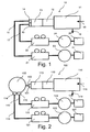
- Fig. 1 shows a butter making machine 10 comprising a separating section 11 into which by means of line 18 row product mass is introduced and butter milk is discharged as a by-product via line 19.
- row product mass normally cream or milk optionally with additives if desired
- the butter making machine has the features of the butter making machine as shown in Fig. 4 . Reference is made to the description thereof.
- the butter mass generated in the separating section 11 is passed to a first working section 12 for further processing. In the first working section 12 there is an inlet 20 for those additives as desired and/or required.
- the water content will be increased up to the legally allowable rate (for instance 16%, but depending on the law of the country the final product is to be sold).
- a second working section 13 wherein the butter mass coming from the first working section 12 is further processed.
- the pumps 14 and 15 are restricting the entrance of produce butter from the working section 13 into the line 16 and line 17, respectively and generating a respective pressure into the line 16 and line 17 such that the butter can be passed to further processing.
- the flow rate of butter into the line connected with the pump can be controlled as required.
- the flow rate of butter into line 16 can be in the range of 0.5 to 5 t per hour and the flow rate of basic butter into line 17 can be in the range of 0.5 to 5 t per hour.
- the pumps 14 and 15 are generating a pressure into the lines 16 and 17 such that the butter emerging from the butter making machine can be passed to distance butter silos.
- each line 16 and 17 there are provided separate dosing units 21 and 22, respectively.
- a butter homogenizer is included in the dosing unit in order to get the required final product quality.
- different additives can be added to the basic butter in order to obtain different butter products.
- Butter products emerging the respective dosing unit are passed further on into respective butter silos 23 and 24. From the butter silos 23 and 24 the butter as passed further into butter packing lines. For instance there are provided one to seven butter packing lines.
- basic butter product in intended to mean a butter product having the normal components of butter.
- any additives which are intended to be added to the at least two different final butter products can be added into the basic product before it is separated.
- flow restricting and generating devices can be used in order to produce mare than two different products with one butter making device.
- three or four or even more flow restricting and generating devices can be used.
- the flow restricting and generating devices are each embodied as a separate pump having the desired capacity.
- the pumps are preferably butter pumps. More preferably the butter pumps have the features of the butter pumps which are sold by the applicant.
- Fig. 2 shows another embodiment in accordance with the invention.
- a conventional butter making machine 110 corresponding to the butter making machine of the embodiment of Fig. 1 .
- At the end of the butter making machine there is one pump 131 feeding the basic butter into line 132 and further into a butter silo 133. It is also possible to feed the basic butter after the butter making machine directly into the butter silo 133 in a conventional matter without having a pump at the outlet of the butter making machine.
- each dosing unit 121 and 122 there are two pumps 114 and 115 provided feeding butter into a dosing unit 121 and 122, respectively. Again a respective butter homogenizer may be included into each dosing unit 121 and 122. All butter emerging the respective dosing units 121 and 122, respectively, is feed into butter packing lines 125 and 126, respectively, in a conventional manner. Two different final butter products are obtained because at the dosing units 123 and 124 different additives can be added to the basic butter as desired and/or required.
- the invention it is possible to have one storage device containing basic butter and passing the butter into at least two separate dosing units for further storage or packing and distributing.
- the storage device can either be the outlet of the normal butter making machine which will be the preferred embodiment of the invention or any storage device like a butter silo.
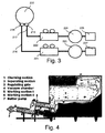
- Fig. 3 is a sketch of a further embodiment of the invention.
- a basic butter product is feed in a butter silo 233 in a conventional manner known to the skilled person in the art.
- At the outlet of the butter silo 233 there are two pumps 214 and 215, preferably butter pumps as mentioned above.
- the pumps 214 and 215 are feeding the basic butter product into lines 216 and 217, respectively.
- the basic butter product is passed on to separate dosing units 221 and 222 as described above in connection with the other embodiments.
- dosing units there are preferably butter homogenisers as stated above.
- the processed and optionally homogenized product is then optionally stored in butter silos 223, 224 and passed onto packing lines 225, 226, respectively, as known to the skilled person in the art. It will also be possible to pass the final butter product directly from the dosing units 221 and 223 to the packing lines 225 and 226, respectively, without having storage means therebetween.
- Fig. 4 shows a schematic sectional side view of a butter making machine which is preferably used in the embodiments of the invention comprising a butter making machine.
- the butter making machine as shown in Fig. 4 comprises a churning section 1 into which row material as cream or milk is feed.
- the processed product is passed along the arrows at the left hand side through a pipe to a separating section 2 where butter milk is separated from the row product.
- the product mass is passed into a working section comprising a first working section 5 and a second working section 6.
- the product is screwed to a flow regulating valve 3 into a vacuum chamber 4. From the vacuum chamber 4 the product is passed further to the second working section 6.
- butter pump 7 for passing the basic butter product onto further processing.
- the butter making machine of Fig. 4 is used for the embodiment of Fig. 1 it is preferred to have at least two separate butter pumps at the outlet of the second working section 6. If used for the embodiment of Fig. 2 , one butter pump or even no butter pump is required because the basic butter product can directly be feed into a butter silo without having a butter pump.
- any butter making machine can be used.
- the regulating valve and the vacuum chamber can be omitted or replaced by other suitable means.
- the present invention relates also to an improved butter making machine having a pump at the end of the first and second working section.
Landscapes
- Life Sciences & Earth Sciences (AREA)
- Animal Husbandry (AREA)
- Environmental Sciences (AREA)
- Dairy Products (AREA)
- Confectionery (AREA)
Description
- The present invention relates to a butter making device.in accordance with the preamble of
claim 1. Such a device is known fromGB-A-689 657 - Butter making devices are known, for instance from the applicant.
- Butter is normally made in a butter making machine. Butter-making machines are known which are divided into three sections:
- churning section
- separating section
- working section, which preferably comprises two stages, i.e. working section I and working section II.
- Normally the machine frame is covered with easilydetachable, smooth finished, stainless steel panels that protect the internal parts of the butter-making machine.
- The various sections of the butter-making machine are provided with frequency converter controlled driving systems.
- The butter making machine is filled with milk or cream. In the separating section butter milk is separated as a by-product. The remaining mass is processed further in a working section which is normally separated into two successive working sections. Normally additives like water and or flavours are added to the butter mass in the working section in order to avoid a contamination of the butter milk with the additives. At the end of the working section the basic butter or special butter (depending on the additives) is discharged and normally passed to a butter silo for storing. Following the butter silo there are normally butter packing lines, for instance one to seven depending on the output rate of the butter making machine. This technique is well known and used to make different butter types on separate butter making machines.
- The new generation of continuous butter making machines meets the most rigorous requirements of modern butter production. New principles in PLC control ensure easy, accurate dosing of water, salt and cultures. However for each different product type a separate butter making machine is needed.
- For butter making machines having two successive working sections, excellent moisture distribution and average water droplet sizes < 0.5 nm are possible due to the double working section. This improves bacteriological quality and increases shelf-life.
- Preferably a very efficient vacuum treatment is provided which makes it possible to reduce the air content in the butter below 0.5% volume resulting in:
- Improved texture and body
- Less risk for oxidation
- Better keeping qualities
- No lamination problems
- This ensures consistent high butter quality. Efficient vacuum treatment results also in easier packing and less down-time on packing machines.
- The butter making machine is flexible:
- The butter-making machine has great flexibility in capacity range and the machine can churn cream with fat content between 25% and 49%.
- Sweet cream, cultured cream and whey cream can be churned on the same machine
- Tempered cold store butter can be pumped to the vacuum chamber - for mixing with freshly churned butter in any proportion
- The butter pump makes it possible to pump the butter over long distances, ensuring flexibility in layout, which is especially important in upgrading existing production facilities.
- Preferably the embodiments of the inventions have these features other features of known butter making machines if they comprise a butter making machine.
- According to the prior art separate butter making machines are needed to make butter with different types, for instance with different additives to be added into the working section. Accordingly there is space and energy needed for each of the separate butter making machines. This is very cost extensive.
- The object of the invention is to provide a butter making device being able to provide at least two different butter types.
- The object of the invention is achieved by a butter making device accordance with the features of at least one of the independent claims. Preferred embodiments of the invention are disclosed in the dependent claims.
- In accordance with an embodiment of the invention there is provided a butter making device comprising a butter containing section containing a basic butter product to be processed further, a dosing unit for adding additives to the basic butter product, a flow restricting and generating device disposed at the butter containing section for passing butter from the butter containing section for further processing the basic butter product to the dosing unit, at least one further dosing unit, and at least one further flow restricting and generating device disposed at the butter containing portion for passing basic butter containing section to the at least one further dosing unit.
- In accordance with the invention at least one of the flow generating and restricting devices can comprise a pump, preferably a butter pump.
- In accordance with the invention at least one of the flow restricting and generating devices can comprise a valve, preferably a regulating valve.
- In accordance with the invention at least two flow restricting and generating devices each can comprise a separate pump, preferably a butter pump.
- In accordance with the invention the butter containing section can be a working section of a butter making machine, preferably the final working section of a butter making machine. Alternatively it can be any butter storage means suitable for the attachment of for instance two or more pumps or equivalent means.
- In accordance with an embodiment of the invention there is provided a method for making butter with the following steps:
- (a) providing a basic butter product in one butter containing section,
- (b) passing the basic butter product to a dosing unit
- (c) adding additives to the basic butter product
- (d) optionally homogenizing the butter product,
- In accordance with the invention at least two flow restricting and generating devices can be are used for separating the basic butter product, wherein each flow restricting and generating device can be used to pass a separated portions of the basic butter product to the respective dosing unit.
- In accordance with the invention at least one of the flow restricting and generating devices can comprise a pump, preferably a butter pump.
- In accordance with the invention at least two flow restricting and generating devices can comprise a separate pump, preferably a butter pump.
- In accordance with the invention at least one of the flow restricting and generating devices can comprise a valve, preferably a regulating valve.
- In accordance with the invention the butter containing section can be the working section of a butter making machine, preferably the final working section of a butter making machine.
- In accordance with the invention the butter containing section can be a butter silo or any other butter storage device.
- In accordance with an embodiment of the invention there is provided a butter making machine comprising the butter making device of
claim 1 with a working section and two pumps disposed at the outlet of the working section. - In accordance with the invention the working section can comprise a first working section and a second working section, wherein preferably a regulating valve and further preferably a vacuum chamber can be provided between the two working section.
- In accordance with the invention the butter making machine can further comprising a separating section and optionally a churning section.
- In accordance with the invention the butter making machine can further comprising a pump, preferably a butter pump at the end of the first working section.
- Preferred embodiments of the invention are shown in the attached drawings.
-
Fig. 1 is a schematic sketch of a butter making device in accordance with the preferred embodiment of the invention. -
Fig. 2 is a schematic sketch of a butter making device in accordance with another embodiment of the invention. -
Fig. 3 is a schematic sketch of a butter making device in accordance with another embodiment of the invention. -
Fig. 4 is a schematic sketch of a butter making machine. -
Fig. 1 shows abutter making machine 10 comprising aseparating section 11 into which by means ofline 18 row product mass is introduced and butter milk is discharged as a by-product vialine 19. Preferably the row product mass (normally cream or milk optionally with additives if desired) has previously be processed in a churning section (not shown inFig. 1 ). Preferably the butter making machine has the features of the butter making machine as shown inFig. 4 . Reference is made to the description thereof. The butter mass generated in theseparating section 11 is passed to a first workingsection 12 for further processing. In the first workingsection 12 there is an inlet 20 for those additives as desired and/or required. For instance the water content will be increased up to the legally allowable rate (forinstance 16%, but depending on the law of the country the final product is to be sold). Following the first workingsection 12 there is asecond working section 13 wherein the butter mass coming from the first workingsection 12 is further processed. At the end of the second workingsection 13 there are at least twopumps line 16 andline 17, respectively. Thepumps section 13 into theline 16 andline 17, respectively and generating a respective pressure into theline 16 andline 17 such that the butter can be passed to further processing. Depending on the speed of the respective pump the flow rate of butter into the line connected with the pump can be controlled as required. For instance the flow rate of butter intoline 16 can be in the range of 0.5 to 5 t per hour and the flow rate of basic butter intoline 17 can be in the range of 0.5 to 5 t per hour. - Normally the flow rate of incoming butter mass into working
section 2 will be little higher than the overall flow rate in theoutput lines 16 and 17 (i.e. the sum of the flow rate inline 16 and the flow rate in line 17) in order to ensure that enough butter is provided at the input of thepumps - The
pumps lines line separate dosing units dosing unit respective butter silos butter silos - The advantages of the invention according to this embodiment will be clearer from the following example. If one wants to make two different butter products with a production rate of 5 t per hour for each product, there was a need for two different butter making machines having a respective output capacity of 5 t per hour. According to the invention it will be possible to use only one butter making machine having a capacity of 10 t per hour wherein the outcoming butter will be separated at the outlet of the second working section into two separate lines with respective flow rates of 5 t per hour. Running one butter making machine having an output capacity of 10 t per hour is much cheaper than running two butter making machines each having an output rate of 5 t per hour. Besides the huge savings in the cost for buying the machine there are also huge savings in the needed space and maintenance of the equipment.
- The same advantages are for smaller or bigger instalments. For instance one machine having a capacity of 1 t per hour can be used instead of two machines having a capacity of 0.5 t per hour.
- In the content of this application the term "basic butter product" in intended to mean a butter product having the normal components of butter. Optionally any additives which are intended to be added to the at least two different final butter products can be added into the basic product before it is separated.
- It is clear that more than two flow restricting and generating devices can be used in order to produce mare than two different products with one butter making device. For instance three or four or even more flow restricting and generating devices can be used. Preferably the flow restricting and generating devices are each embodied as a separate pump having the desired capacity. The pumps are preferably butter pumps. More preferably the butter pumps have the features of the butter pumps which are sold by the applicant.
-
Fig. 2 shows another embodiment in accordance with the invention. There is a conventional butter making machine 110 corresponding to the butter making machine of the embodiment ofFig. 1 . Reference is made to the description thereof. At the end of the butter making machine there is onepump 131 feeding the basic butter intoline 132 and further into abutter silo 133. It is also possible to feed the basic butter after the butter making machine directly into thebutter silo 133 in a conventional matter without having a pump at the outlet of the butter making machine. - At the outlet of the butter silo there are two
pumps dosing unit dosing unit respective dosing units butter packing lines 125 and 126, respectively, in a conventional manner. Two different final butter products are obtained because at thedosing units - According to the invention it is possible to have one storage device containing basic butter and passing the butter into at least two separate dosing units for further storage or packing and distributing. The storage device can either be the outlet of the normal butter making machine which will be the preferred embodiment of the invention or any storage device like a butter silo.
-
Fig. 3 is a sketch of a further embodiment of the invention. A basic butter product is feed in abutter silo 233 in a conventional manner known to the skilled person in the art. At the outlet of thebutter silo 233 there are twopumps pumps lines dosing units dosing units butter silos lines 225, 226, respectively, as known to the skilled person in the art. It will also be possible to pass the final butter product directly from thedosing units packing lines 225 and 226, respectively, without having storage means therebetween. -
Fig. 4 shows a schematic sectional side view of a butter making machine which is preferably used in the embodiments of the invention comprising a butter making machine. - The butter making machine as shown in
Fig. 4 comprises achurning section 1 into which row material as cream or milk is feed. The processed product is passed along the arrows at the left hand side through a pipe to aseparating section 2 where butter milk is separated from the row product. The product mass is passed into a working section comprising a first working section 5 and asecond working section 6. In the first working section 5 the product is screwed to aflow regulating valve 3 into avacuum chamber 4. From thevacuum chamber 4 the product is passed further to thesecond working section 6. At the end of thesecond working section 6 there isbutter pump 7 for passing the basic butter product onto further processing. - If the butter making machine of
Fig. 4 is used for the embodiment ofFig. 1 it is preferred to have at least two separate butter pumps at the outlet of thesecond working section 6. If used for the embodiment ofFig. 2 , one butter pump or even no butter pump is required because the basic butter product can directly be feed into a butter silo without having a butter pump. - It is clear that any butter making machine can be used. For instance the regulating valve and the vacuum chamber can be omitted or replaced by other suitable means.
- According to another aspect of the invention it will be advantageous to replace the flow regulation valve after the first working section I by a pump, preferably a butter pump. The advantage will be that the output rate of the first working section I will than be independent from the pressure applied thereon by the material feed into the first working section because it will be determined by the rate with which the pump is pumping material into the vacuum chamber (or the second working section if the vacuum chamber is omitted). Accordingly the input pressure can be regulated independent from the output rate. Varying the input pressure will have an effect to the parameters of the resulting product. Therefore providing a pump at the end of the first working section will provide the advantage that the butter making machine can be adjusted to the requirements much more conveniently and with more options. Accordingly the present invention relates also to an improved butter making machine having a pump at the end of the first and second working section.
- It is clear that the description of the specific embodiments of the invention is not be intended to limit the scope of protection which is defined by the claims. It is also clear that obvious alternatives which the skilled person will notice by reading the specification, are intended to be in the scope of protection as defined by the claims.
Claims (15)
- A butter making device comprising
a butter containing section (13) containing a basic butter product to be processed further,
a dosing unit (21) for adding additives to the basic butter product, and a flow restricting and generating device (14) disposed at the butter containing section (13) allowing for passing butter from the butter containing section to the dosing unit (21) for further processing of the basic butter product,
characterized by at least one further dosing unit (22) and at least one further flow restricting and generating device (15) disposed at the butter containing section (13) for passing basic butter from the butter containing section to the at least one further dosing unit. - The butter making device of claim 1, wherein at least one of the flow generating and restricting devices comprises a pump, preferably a butter pump.
- The butter making device of any of the preceding claims, wherein at least one of the flow restricting and generating devices comprises a valve, preferably a regulating valve.
- The butter making device of any of the preceding claims, wherein the at least two flow restricting and generating devices each comprise a separate pump, preferably a butter pump.
- The butter making device of any of the preceding claims, wherein the butter containing section is a working section of a butter making machine, preferably the final working section of a butter making machine.
- A butter making machine comprising the butter making device of any of the preceding claims, further comprising a working section and two pumps disposed at the outlet of the working section.
- The butter making machine of claim 6, wherein the working section comprises a first working section and a second working section, wherein preferably a regulating valve and further preferably a vacuum chamber are provided between the two working sections.
- The butter making machine of claims 6 or 7, further comprising a separating section and optionally a churning section.
- A method for making butter with the following steps:(a) providing a basic butter product in one butter containing section,(b) passing the basic butter product to a dosing unit(c) adding additives to the basic butter product(d) optionally homogenizing the butter product,characterized in that in step (b) the basic butter product is separated and passed to at least two separated dosing units, and that in each dosing unit additives are added to the basis butter product as desired in order to obtain separately two different butter products.
- The method of claim 9, wherein for separating the basic butter product at least two flow restricting and generating devices are used, wherein each flow restricting and generating device is used to pass separated portions of the basic butter product to the respective dosing units.
- The method of claim 9 or 10, wherein at least one of the flow restricting and generating devices comprises a pump, preferably a butter pump.
- The method of any of claims 9 to 11, wherein the at least two flow restricting and generating devices each comprise a separate pump, preferably a butter pump.
- The method of any of claims 9 to 12, wherein at least one of the flow restricting and generating devices comprises a valve, preferably a regulating valve.
- The method of any of the claims 9 to 13, wherein the butter containing section is the working section of a butter making machine, preferably the final working section of a butter making machine.
- The method of any of the claims 9 to 14, wherein the butter containing section is a butter silo or any other butter storage device.
Priority Applications (2)
| Application Number | Priority Date | Filing Date | Title |
|---|---|---|---|
| EP07819731.6A EP2083616B1 (en) | 2006-11-11 | 2007-11-09 | Butter making device |
| PL07819731T PL2083616T3 (en) | 2006-11-11 | 2007-11-09 | Butter making device |
Applications Claiming Priority (3)
| Application Number | Priority Date | Filing Date | Title |
|---|---|---|---|
| EP20060023509 EP1920650B1 (en) | 2006-11-11 | 2006-11-11 | Butter making device |
| PCT/EP2007/009738 WO2008058684A1 (en) | 2006-11-11 | 2007-11-09 | Butter making device |
| EP07819731.6A EP2083616B1 (en) | 2006-11-11 | 2007-11-09 | Butter making device |
Publications (2)
| Publication Number | Publication Date |
|---|---|
| EP2083616A1 EP2083616A1 (en) | 2009-08-05 |
| EP2083616B1 true EP2083616B1 (en) | 2016-09-28 |
Family
ID=37845267
Family Applications (2)
| Application Number | Title | Priority Date | Filing Date |
|---|---|---|---|
| EP20060023509 Active EP1920650B1 (en) | 2006-11-11 | 2006-11-11 | Butter making device |
| EP07819731.6A Not-in-force EP2083616B1 (en) | 2006-11-11 | 2007-11-09 | Butter making device |
Family Applications Before (1)
| Application Number | Title | Priority Date | Filing Date |
|---|---|---|---|
| EP20060023509 Active EP1920650B1 (en) | 2006-11-11 | 2006-11-11 | Butter making device |
Country Status (8)
| Country | Link |
|---|---|
| US (1) | US8642105B2 (en) |
| EP (2) | EP1920650B1 (en) |
| AU (1) | AU2007321465B2 (en) |
| DK (2) | DK1920650T3 (en) |
| ES (1) | ES2422106T3 (en) |
| NZ (1) | NZ577544A (en) |
| PL (2) | PL1920650T3 (en) |
| WO (1) | WO2008058684A1 (en) |
Families Citing this family (3)
| Publication number | Priority date | Publication date | Assignee | Title |
|---|---|---|---|---|
| DE102009044429A1 (en) | 2009-11-05 | 2011-05-12 | Gea Westfalia Separator Gmbh | Apparatus and method for producing a plurality of butters |
| US10245604B2 (en) | 2014-12-30 | 2019-04-02 | Brevda Inc. | Apparatus and method for dispensing liquefied fluid |
| USD838178S1 (en) | 2015-12-30 | 2019-01-15 | Brevda Inc. | Apparatus for dispensing liquefied fluid |
Citations (1)
| Publication number | Priority date | Publication date | Assignee | Title |
|---|---|---|---|---|
| EP0683975A1 (en) * | 1994-05-26 | 1995-11-29 | Ing. E. Vezzadini E C. S.R.L. | Unit for feeding pasty substances, in particular butter, to a metering machine |
Family Cites Families (5)
| Publication number | Priority date | Publication date | Assignee | Title |
|---|---|---|---|---|
| US2395051A (en) * | 1941-12-13 | 1946-02-19 | Cherry Burrell Corp | Buttermaking means |
| GB689657A (en) * | 1949-11-21 | 1953-04-01 | Westfalia Separator Akt Ges | Process and apparatus for continuous butter-making |
| DE2916625A1 (en) * | 1979-04-25 | 1980-11-06 | Westfalia Separator Ag | DEVICE FOR PRODUCING BUTTER IN A CONTINUOUSLY WORKING BUTTERING MACHINE |
| DE3426280C1 (en) * | 1984-07-17 | 1985-11-07 | Westfalia Separator Ag, 4740 Oelde | Continuously operating butter machine |
| DK446987A (en) * | 1986-09-27 | 1988-03-28 | Westfalia Separator Ag | METHOD OF BUTTER MANUFACTURING |
-
2006
- 2006-11-11 EP EP20060023509 patent/EP1920650B1/en active Active
- 2006-11-11 DK DK06023509T patent/DK1920650T3/en active
- 2006-11-11 PL PL06023509T patent/PL1920650T3/en unknown
- 2006-11-11 ES ES06023509T patent/ES2422106T3/en active Active
-
2007
- 2007-11-09 EP EP07819731.6A patent/EP2083616B1/en not_active Not-in-force
- 2007-11-09 US US12/514,427 patent/US8642105B2/en not_active Expired - Fee Related
- 2007-11-09 AU AU2007321465A patent/AU2007321465B2/en active Active
- 2007-11-09 DK DK07819731.6T patent/DK2083616T3/en active
- 2007-11-09 WO PCT/EP2007/009738 patent/WO2008058684A1/en not_active Ceased
- 2007-11-09 NZ NZ577544A patent/NZ577544A/en unknown
- 2007-11-09 PL PL07819731T patent/PL2083616T3/en unknown
Patent Citations (1)
| Publication number | Priority date | Publication date | Assignee | Title |
|---|---|---|---|---|
| EP0683975A1 (en) * | 1994-05-26 | 1995-11-29 | Ing. E. Vezzadini E C. S.R.L. | Unit for feeding pasty substances, in particular butter, to a metering machine |
Also Published As
| Publication number | Publication date |
|---|---|
| WO2008058684A1 (en) | 2008-05-22 |
| US20110206822A1 (en) | 2011-08-25 |
| ES2422106T3 (en) | 2013-09-06 |
| NZ577544A (en) | 2011-11-25 |
| PL1920650T3 (en) | 2014-01-31 |
| EP2083616A1 (en) | 2009-08-05 |
| PL2083616T3 (en) | 2017-08-31 |
| AU2007321465A1 (en) | 2008-05-22 |
| DK1920650T3 (en) | 2013-07-22 |
| AU2007321465B2 (en) | 2013-02-21 |
| EP1920650B1 (en) | 2013-04-17 |
| US8642105B2 (en) | 2014-02-04 |
| EP1920650A1 (en) | 2008-05-14 |
| DK2083616T3 (en) | 2017-01-16 |
Similar Documents
| Publication | Publication Date | Title |
|---|---|---|
| US10258017B2 (en) | Continuous cooker stretcher and methods of use thereof | |
| US8642105B2 (en) | Butter making device | |
| CA2748217C (en) | Method and device for producing a product by microgelling and/or microparticulation of a preparation | |
| US8221816B1 (en) | Process for preparing low moisture filata cheese | |
| EP2154980B1 (en) | System for pasteurizing animal food | |
| US7758905B2 (en) | Method and system for making extruded portions of cheese | |
| EP2895002B1 (en) | Method, use and apparatus for continuous reversal or breaking of an oil-in-water emulsion food product by means of hydrodynamic cavitation | |
| EP1712271A2 (en) | Apparatus for homogenizing and/or dispersing flowable materials | |
| AU2804795A (en) | Process for continuous production of processed cheese | |
| EP3505457B1 (en) | Producing an aseptic food product | |
| Kilara | Basic dairy processing principles | |
| EP2327312B1 (en) | Optimisation of a butter-making method with small amounts of cream | |
| EP0499614B1 (en) | A process for the production of low fat butter and an assembly to be used when carrying out said process | |
| EP1121862B1 (en) | Methods and means for preparing cheese coatings | |
| JP2017018594A (en) | Flyer | |
| WO1982000240A1 (en) | A method and a plant for making a liquid milk product | |
| EP1673989B1 (en) | Apparatus and method for treating food products | |
| SU1736379A1 (en) | Acid curd and cheese production line | |
| WO2009034399A1 (en) | Apparatus for forming foodstuff masses by extrusion | |
| Kilara | Principles of dairy processing |
Legal Events
| Date | Code | Title | Description |
|---|---|---|---|
| PUAI | Public reference made under article 153(3) epc to a published international application that has entered the european phase |
Free format text: ORIGINAL CODE: 0009012 |
|
| 17P | Request for examination filed |
Effective date: 20090511 |
|
| AK | Designated contracting states |
Kind code of ref document: A1 Designated state(s): AT BE BG CH CY CZ DE DK EE ES FI FR GB GR HU IE IS IT LI LT LU LV MC MT NL PL PT RO SE SI SK TR |
|
| DAX | Request for extension of the european patent (deleted) | ||
| 17Q | First examination report despatched |
Effective date: 20150417 |
|
| RAP1 | Party data changed (applicant data changed or rights of an application transferred) |
Owner name: SPX FLOW TECHNOLOGY DANMARK A/S |
|
| GRAP | Despatch of communication of intention to grant a patent |
Free format text: ORIGINAL CODE: EPIDOSNIGR1 |
|
| INTG | Intention to grant announced |
Effective date: 20160509 |
|
| GRAS | Grant fee paid |
Free format text: ORIGINAL CODE: EPIDOSNIGR3 |
|
| GRAA | (expected) grant |
Free format text: ORIGINAL CODE: 0009210 |
|
| AK | Designated contracting states |
Kind code of ref document: B1 Designated state(s): AT BE BG CH CY CZ DE DK EE ES FI FR GB GR HU IE IS IT LI LT LU LV MC MT NL PL PT RO SE SI SK TR |
|
| REG | Reference to a national code |
Ref country code: GB Ref legal event code: FG4D |
|
| REG | Reference to a national code |
Ref country code: CH Ref legal event code: EP |
|
| REG | Reference to a national code |
Ref country code: AT Ref legal event code: REF Ref document number: 831977 Country of ref document: AT Kind code of ref document: T Effective date: 20161015 |
|
| REG | Reference to a national code |
Ref country code: IE Ref legal event code: FG4D |
|
| REG | Reference to a national code |
Ref country code: DE Ref legal event code: R096 Ref document number: 602007048123 Country of ref document: DE |
|
| REG | Reference to a national code |
Ref country code: FR Ref legal event code: PLFP Year of fee payment: 10 |
|
| REG | Reference to a national code |
Ref country code: NL Ref legal event code: FP |
|
| REG | Reference to a national code |
Ref country code: SE Ref legal event code: TRGR |
|
| REG | Reference to a national code |
Ref country code: DK Ref legal event code: T3 Effective date: 20170110 |
|
| REG | Reference to a national code |
Ref country code: LT Ref legal event code: MG4D |
|
| PG25 | Lapsed in a contracting state [announced via postgrant information from national office to epo] |
Ref country code: FI Free format text: LAPSE BECAUSE OF FAILURE TO SUBMIT A TRANSLATION OF THE DESCRIPTION OR TO PAY THE FEE WITHIN THE PRESCRIBED TIME-LIMIT Effective date: 20160928 Ref country code: LT Free format text: LAPSE BECAUSE OF FAILURE TO SUBMIT A TRANSLATION OF THE DESCRIPTION OR TO PAY THE FEE WITHIN THE PRESCRIBED TIME-LIMIT Effective date: 20160928 |
|
| REG | Reference to a national code |
Ref country code: AT Ref legal event code: MK05 Ref document number: 831977 Country of ref document: AT Kind code of ref document: T Effective date: 20160928 |
|
| PG25 | Lapsed in a contracting state [announced via postgrant information from national office to epo] |
Ref country code: LV Free format text: LAPSE BECAUSE OF FAILURE TO SUBMIT A TRANSLATION OF THE DESCRIPTION OR TO PAY THE FEE WITHIN THE PRESCRIBED TIME-LIMIT Effective date: 20160928 Ref country code: GR Free format text: LAPSE BECAUSE OF FAILURE TO SUBMIT A TRANSLATION OF THE DESCRIPTION OR TO PAY THE FEE WITHIN THE PRESCRIBED TIME-LIMIT Effective date: 20161229 |
|
| PGFP | Annual fee paid to national office [announced via postgrant information from national office to epo] |
Ref country code: ES Payment date: 20161128 Year of fee payment: 10 |
|
| PG25 | Lapsed in a contracting state [announced via postgrant information from national office to epo] |
Ref country code: RO Free format text: LAPSE BECAUSE OF FAILURE TO SUBMIT A TRANSLATION OF THE DESCRIPTION OR TO PAY THE FEE WITHIN THE PRESCRIBED TIME-LIMIT Effective date: 20160928 Ref country code: EE Free format text: LAPSE BECAUSE OF FAILURE TO SUBMIT A TRANSLATION OF THE DESCRIPTION OR TO PAY THE FEE WITHIN THE PRESCRIBED TIME-LIMIT Effective date: 20160928 |
|
| PG25 | Lapsed in a contracting state [announced via postgrant information from national office to epo] |
Ref country code: ES Free format text: LAPSE BECAUSE OF FAILURE TO SUBMIT A TRANSLATION OF THE DESCRIPTION OR TO PAY THE FEE WITHIN THE PRESCRIBED TIME-LIMIT Effective date: 20160928 Ref country code: BG Free format text: LAPSE BECAUSE OF FAILURE TO SUBMIT A TRANSLATION OF THE DESCRIPTION OR TO PAY THE FEE WITHIN THE PRESCRIBED TIME-LIMIT Effective date: 20161228 Ref country code: SK Free format text: LAPSE BECAUSE OF FAILURE TO SUBMIT A TRANSLATION OF THE DESCRIPTION OR TO PAY THE FEE WITHIN THE PRESCRIBED TIME-LIMIT Effective date: 20160928 Ref country code: AT Free format text: LAPSE BECAUSE OF FAILURE TO SUBMIT A TRANSLATION OF THE DESCRIPTION OR TO PAY THE FEE WITHIN THE PRESCRIBED TIME-LIMIT Effective date: 20160928 Ref country code: CZ Free format text: LAPSE BECAUSE OF FAILURE TO SUBMIT A TRANSLATION OF THE DESCRIPTION OR TO PAY THE FEE WITHIN THE PRESCRIBED TIME-LIMIT Effective date: 20160928 Ref country code: IS Free format text: LAPSE BECAUSE OF FAILURE TO SUBMIT A TRANSLATION OF THE DESCRIPTION OR TO PAY THE FEE WITHIN THE PRESCRIBED TIME-LIMIT Effective date: 20170128 Ref country code: PT Free format text: LAPSE BECAUSE OF FAILURE TO SUBMIT A TRANSLATION OF THE DESCRIPTION OR TO PAY THE FEE WITHIN THE PRESCRIBED TIME-LIMIT Effective date: 20170130 |
|
| REG | Reference to a national code |
Ref country code: DE Ref legal event code: R097 Ref document number: 602007048123 Country of ref document: DE |
|
| PG25 | Lapsed in a contracting state [announced via postgrant information from national office to epo] |
Ref country code: IT Free format text: LAPSE BECAUSE OF FAILURE TO SUBMIT A TRANSLATION OF THE DESCRIPTION OR TO PAY THE FEE WITHIN THE PRESCRIBED TIME-LIMIT Effective date: 20160928 |
|
| REG | Reference to a national code |
Ref country code: CH Ref legal event code: PL |
|
| PG25 | Lapsed in a contracting state [announced via postgrant information from national office to epo] |
Ref country code: LI Free format text: LAPSE BECAUSE OF NON-PAYMENT OF DUE FEES Effective date: 20161130 Ref country code: CH Free format text: LAPSE BECAUSE OF NON-PAYMENT OF DUE FEES Effective date: 20161130 |
|
| PLBE | No opposition filed within time limit |
Free format text: ORIGINAL CODE: 0009261 |
|
| STAA | Information on the status of an ep patent application or granted ep patent |
Free format text: STATUS: NO OPPOSITION FILED WITHIN TIME LIMIT |
|
| REG | Reference to a national code |
Ref country code: IE Ref legal event code: MM4A |
|
| PGFP | Annual fee paid to national office [announced via postgrant information from national office to epo] |
Ref country code: PL Payment date: 20161201 Year of fee payment: 10 |
|
| 26N | No opposition filed |
Effective date: 20170629 |
|
| PG25 | Lapsed in a contracting state [announced via postgrant information from national office to epo] |
Ref country code: LU Free format text: LAPSE BECAUSE OF NON-PAYMENT OF DUE FEES Effective date: 20161130 |
|
| REG | Reference to a national code |
Ref country code: FR Ref legal event code: PLFP Year of fee payment: 11 |
|
| PG25 | Lapsed in a contracting state [announced via postgrant information from national office to epo] |
Ref country code: SI Free format text: LAPSE BECAUSE OF FAILURE TO SUBMIT A TRANSLATION OF THE DESCRIPTION OR TO PAY THE FEE WITHIN THE PRESCRIBED TIME-LIMIT Effective date: 20160928 Ref country code: IE Free format text: LAPSE BECAUSE OF NON-PAYMENT OF DUE FEES Effective date: 20161109 |
|
| PG25 | Lapsed in a contracting state [announced via postgrant information from national office to epo] |
Ref country code: HU Free format text: LAPSE BECAUSE OF FAILURE TO SUBMIT A TRANSLATION OF THE DESCRIPTION OR TO PAY THE FEE WITHIN THE PRESCRIBED TIME-LIMIT; INVALID AB INITIO Effective date: 20071109 Ref country code: CY Free format text: LAPSE BECAUSE OF FAILURE TO SUBMIT A TRANSLATION OF THE DESCRIPTION OR TO PAY THE FEE WITHIN THE PRESCRIBED TIME-LIMIT Effective date: 20160928 |
|
| PG25 | Lapsed in a contracting state [announced via postgrant information from national office to epo] |
Ref country code: TR Free format text: LAPSE BECAUSE OF FAILURE TO SUBMIT A TRANSLATION OF THE DESCRIPTION OR TO PAY THE FEE WITHIN THE PRESCRIBED TIME-LIMIT Effective date: 20160928 Ref country code: MC Free format text: LAPSE BECAUSE OF FAILURE TO SUBMIT A TRANSLATION OF THE DESCRIPTION OR TO PAY THE FEE WITHIN THE PRESCRIBED TIME-LIMIT Effective date: 20160928 |
|
| PG25 | Lapsed in a contracting state [announced via postgrant information from national office to epo] |
Ref country code: MT Free format text: LAPSE BECAUSE OF NON-PAYMENT OF DUE FEES Effective date: 20161109 |
|
| REG | Reference to a national code |
Ref country code: FR Ref legal event code: PLFP Year of fee payment: 12 |
|
| PGFP | Annual fee paid to national office [announced via postgrant information from national office to epo] |
Ref country code: BE Payment date: 20180914 Year of fee payment: 12 |
|
| PGFP | Annual fee paid to national office [announced via postgrant information from national office to epo] |
Ref country code: NL Payment date: 20181114 Year of fee payment: 12 |
|
| PGFP | Annual fee paid to national office [announced via postgrant information from national office to epo] |
Ref country code: DE Payment date: 20181030 Year of fee payment: 12 Ref country code: SE Payment date: 20181113 Year of fee payment: 12 Ref country code: DK Payment date: 20181109 Year of fee payment: 12 |
|
| PGFP | Annual fee paid to national office [announced via postgrant information from national office to epo] |
Ref country code: FR Payment date: 20181011 Year of fee payment: 12 Ref country code: GB Payment date: 20181107 Year of fee payment: 12 |
|
| PG25 | Lapsed in a contracting state [announced via postgrant information from national office to epo] |
Ref country code: PL Free format text: LAPSE BECAUSE OF NON-PAYMENT OF DUE FEES Effective date: 20171109 |
|
| REG | Reference to a national code |
Ref country code: DE Ref legal event code: R119 Ref document number: 602007048123 Country of ref document: DE |
|
| REG | Reference to a national code |
Ref country code: DK Ref legal event code: EBP Effective date: 20191130 |
|
| REG | Reference to a national code |
Ref country code: SE Ref legal event code: EUG |
|
| REG | Reference to a national code |
Ref country code: NL Ref legal event code: MM Effective date: 20191201 |
|
| REG | Reference to a national code |
Ref country code: BE Ref legal event code: MM Effective date: 20191130 |
|
| PG25 | Lapsed in a contracting state [announced via postgrant information from national office to epo] |
Ref country code: SE Free format text: LAPSE BECAUSE OF NON-PAYMENT OF DUE FEES Effective date: 20191110 |
|
| GBPC | Gb: european patent ceased through non-payment of renewal fee |
Effective date: 20191109 |
|
| PG25 | Lapsed in a contracting state [announced via postgrant information from national office to epo] |
Ref country code: NL Free format text: LAPSE BECAUSE OF NON-PAYMENT OF DUE FEES Effective date: 20191201 |
|
| PG25 | Lapsed in a contracting state [announced via postgrant information from national office to epo] |
Ref country code: FR Free format text: LAPSE BECAUSE OF NON-PAYMENT OF DUE FEES Effective date: 20191130 Ref country code: DE Free format text: LAPSE BECAUSE OF NON-PAYMENT OF DUE FEES Effective date: 20200603 Ref country code: DK Free format text: LAPSE BECAUSE OF NON-PAYMENT OF DUE FEES Effective date: 20191130 Ref country code: GB Free format text: LAPSE BECAUSE OF NON-PAYMENT OF DUE FEES Effective date: 20191109 |
|
| PG25 | Lapsed in a contracting state [announced via postgrant information from national office to epo] |
Ref country code: BE Free format text: LAPSE BECAUSE OF NON-PAYMENT OF DUE FEES Effective date: 20191130 |
|
| P01 | Opt-out of the competence of the unified patent court (upc) registered |
Effective date: 20230528 |