EP2083198A2 - Method and control unit for controlling a power train that has a double clutch - Google Patents
Method and control unit for controlling a power train that has a double clutch Download PDFInfo
- Publication number
- EP2083198A2 EP2083198A2 EP08018976A EP08018976A EP2083198A2 EP 2083198 A2 EP2083198 A2 EP 2083198A2 EP 08018976 A EP08018976 A EP 08018976A EP 08018976 A EP08018976 A EP 08018976A EP 2083198 A2 EP2083198 A2 EP 2083198A2
- Authority
- EP
- European Patent Office
- Prior art keywords
- clutch
- speed
- nmot
- gear
- threshold
- Prior art date
- Legal status (The legal status is an assumption and is not a legal conclusion. Google has not performed a legal analysis and makes no representation as to the accuracy of the status listed.)
- Withdrawn
Links
Images


Classifications
-
- F—MECHANICAL ENGINEERING; LIGHTING; HEATING; WEAPONS; BLASTING
- F16—ENGINEERING ELEMENTS AND UNITS; GENERAL MEASURES FOR PRODUCING AND MAINTAINING EFFECTIVE FUNCTIONING OF MACHINES OR INSTALLATIONS; THERMAL INSULATION IN GENERAL
- F16H—GEARING
- F16H61/00—Control functions within control units of change-speed- or reversing-gearings for conveying rotary motion ; Control of exclusively fluid gearing, friction gearing, gearings with endless flexible members or other particular types of gearing
- F16H61/04—Smoothing ratio shift
- F16H61/0437—Smoothing ratio shift by using electrical signals
-
- B—PERFORMING OPERATIONS; TRANSPORTING
- B60—VEHICLES IN GENERAL
- B60W—CONJOINT CONTROL OF VEHICLE SUB-UNITS OF DIFFERENT TYPE OR DIFFERENT FUNCTION; CONTROL SYSTEMS SPECIALLY ADAPTED FOR HYBRID VEHICLES; ROAD VEHICLE DRIVE CONTROL SYSTEMS FOR PURPOSES NOT RELATED TO THE CONTROL OF A PARTICULAR SUB-UNIT
- B60W10/00—Conjoint control of vehicle sub-units of different type or different function
- B60W10/10—Conjoint control of vehicle sub-units of different type or different function including control of change-speed gearings
- B60W10/11—Stepped gearings
- B60W10/113—Stepped gearings with two input flow paths, e.g. double clutch transmission selection of one of the torque flow paths by the corresponding input clutch
-
- B—PERFORMING OPERATIONS; TRANSPORTING
- B60—VEHICLES IN GENERAL
- B60W—CONJOINT CONTROL OF VEHICLE SUB-UNITS OF DIFFERENT TYPE OR DIFFERENT FUNCTION; CONTROL SYSTEMS SPECIALLY ADAPTED FOR HYBRID VEHICLES; ROAD VEHICLE DRIVE CONTROL SYSTEMS FOR PURPOSES NOT RELATED TO THE CONTROL OF A PARTICULAR SUB-UNIT
- B60W30/00—Purposes of road vehicle drive control systems not related to the control of a particular sub-unit, e.g. of systems using conjoint control of vehicle sub-units, or advanced driver assistance systems for ensuring comfort, stability and safety or drive control systems for propelling or retarding the vehicle
- B60W30/18—Propelling the vehicle
- B60W30/18009—Propelling the vehicle related to particular drive situations
- B60W30/18063—Creeping
-
- B—PERFORMING OPERATIONS; TRANSPORTING
- B60—VEHICLES IN GENERAL
- B60W—CONJOINT CONTROL OF VEHICLE SUB-UNITS OF DIFFERENT TYPE OR DIFFERENT FUNCTION; CONTROL SYSTEMS SPECIALLY ADAPTED FOR HYBRID VEHICLES; ROAD VEHICLE DRIVE CONTROL SYSTEMS FOR PURPOSES NOT RELATED TO THE CONTROL OF A PARTICULAR SUB-UNIT
- B60W30/00—Purposes of road vehicle drive control systems not related to the control of a particular sub-unit, e.g. of systems using conjoint control of vehicle sub-units, or advanced driver assistance systems for ensuring comfort, stability and safety or drive control systems for propelling or retarding the vehicle
- B60W30/18—Propelling the vehicle
- B60W30/18009—Propelling the vehicle related to particular drive situations
- B60W30/181—Preparing for stopping
-
- B—PERFORMING OPERATIONS; TRANSPORTING
- B60—VEHICLES IN GENERAL
- B60W—CONJOINT CONTROL OF VEHICLE SUB-UNITS OF DIFFERENT TYPE OR DIFFERENT FUNCTION; CONTROL SYSTEMS SPECIALLY ADAPTED FOR HYBRID VEHICLES; ROAD VEHICLE DRIVE CONTROL SYSTEMS FOR PURPOSES NOT RELATED TO THE CONTROL OF A PARTICULAR SUB-UNIT
- B60W30/00—Purposes of road vehicle drive control systems not related to the control of a particular sub-unit, e.g. of systems using conjoint control of vehicle sub-units, or advanced driver assistance systems for ensuring comfort, stability and safety or drive control systems for propelling or retarding the vehicle
- B60W30/18—Propelling the vehicle
- B60W30/20—Reducing vibrations in the driveline
-
- F—MECHANICAL ENGINEERING; LIGHTING; HEATING; WEAPONS; BLASTING
- F16—ENGINEERING ELEMENTS AND UNITS; GENERAL MEASURES FOR PRODUCING AND MAINTAINING EFFECTIVE FUNCTIONING OF MACHINES OR INSTALLATIONS; THERMAL INSULATION IN GENERAL
- F16H—GEARING
- F16H61/00—Control functions within control units of change-speed- or reversing-gearings for conveying rotary motion ; Control of exclusively fluid gearing, friction gearing, gearings with endless flexible members or other particular types of gearing
- F16H61/68—Control functions within control units of change-speed- or reversing-gearings for conveying rotary motion ; Control of exclusively fluid gearing, friction gearing, gearings with endless flexible members or other particular types of gearing specially adapted for stepped gearings
- F16H61/684—Control functions within control units of change-speed- or reversing-gearings for conveying rotary motion ; Control of exclusively fluid gearing, friction gearing, gearings with endless flexible members or other particular types of gearing specially adapted for stepped gearings without interruption of drive
- F16H61/688—Control functions within control units of change-speed- or reversing-gearings for conveying rotary motion ; Control of exclusively fluid gearing, friction gearing, gearings with endless flexible members or other particular types of gearing specially adapted for stepped gearings without interruption of drive with two inputs, e.g. selection of one of two torque-flow paths by clutches
-
- B—PERFORMING OPERATIONS; TRANSPORTING
- B60—VEHICLES IN GENERAL
- B60W—CONJOINT CONTROL OF VEHICLE SUB-UNITS OF DIFFERENT TYPE OR DIFFERENT FUNCTION; CONTROL SYSTEMS SPECIALLY ADAPTED FOR HYBRID VEHICLES; ROAD VEHICLE DRIVE CONTROL SYSTEMS FOR PURPOSES NOT RELATED TO THE CONTROL OF A PARTICULAR SUB-UNIT
- B60W2710/00—Output or target parameters relating to a particular sub-units
- B60W2710/06—Combustion engines, Gas turbines
- B60W2710/0644—Engine speed
- B60W2710/065—Idle condition
-
- F—MECHANICAL ENGINEERING; LIGHTING; HEATING; WEAPONS; BLASTING
- F16—ENGINEERING ELEMENTS AND UNITS; GENERAL MEASURES FOR PRODUCING AND MAINTAINING EFFECTIVE FUNCTIONING OF MACHINES OR INSTALLATIONS; THERMAL INSULATION IN GENERAL
- F16D—COUPLINGS FOR TRANSMITTING ROTATION; CLUTCHES; BRAKES
- F16D2500/00—External control of clutches by electric or electronic means
- F16D2500/10—System to be controlled
- F16D2500/108—Gear
- F16D2500/1086—Concentric shafts
-
- F—MECHANICAL ENGINEERING; LIGHTING; HEATING; WEAPONS; BLASTING
- F16—ENGINEERING ELEMENTS AND UNITS; GENERAL MEASURES FOR PRODUCING AND MAINTAINING EFFECTIVE FUNCTIONING OF MACHINES OR INSTALLATIONS; THERMAL INSULATION IN GENERAL
- F16D—COUPLINGS FOR TRANSMITTING ROTATION; CLUTCHES; BRAKES
- F16D2500/00—External control of clutches by electric or electronic means
- F16D2500/30—Signal inputs
- F16D2500/306—Signal inputs from the engine
- F16D2500/3067—Speed of the engine
-
- F—MECHANICAL ENGINEERING; LIGHTING; HEATING; WEAPONS; BLASTING
- F16—ENGINEERING ELEMENTS AND UNITS; GENERAL MEASURES FOR PRODUCING AND MAINTAINING EFFECTIVE FUNCTIONING OF MACHINES OR INSTALLATIONS; THERMAL INSULATION IN GENERAL
- F16D—COUPLINGS FOR TRANSMITTING ROTATION; CLUTCHES; BRAKES
- F16D2500/00—External control of clutches by electric or electronic means
- F16D2500/70—Details about the implementation of the control system
- F16D2500/704—Output parameters from the control unit; Target parameters to be controlled
- F16D2500/70422—Clutch parameters
- F16D2500/70432—From the input shaft
- F16D2500/70436—Input shaft speed
-
- F—MECHANICAL ENGINEERING; LIGHTING; HEATING; WEAPONS; BLASTING
- F16—ENGINEERING ELEMENTS AND UNITS; GENERAL MEASURES FOR PRODUCING AND MAINTAINING EFFECTIVE FUNCTIONING OF MACHINES OR INSTALLATIONS; THERMAL INSULATION IN GENERAL
- F16D—COUPLINGS FOR TRANSMITTING ROTATION; CLUTCHES; BRAKES
- F16D2500/00—External control of clutches by electric or electronic means
- F16D2500/70—Details about the implementation of the control system
- F16D2500/704—Output parameters from the control unit; Target parameters to be controlled
- F16D2500/70452—Engine parameters
- F16D2500/70454—Engine speed
-
- F—MECHANICAL ENGINEERING; LIGHTING; HEATING; WEAPONS; BLASTING
- F16—ENGINEERING ELEMENTS AND UNITS; GENERAL MEASURES FOR PRODUCING AND MAINTAINING EFFECTIVE FUNCTIONING OF MACHINES OR INSTALLATIONS; THERMAL INSULATION IN GENERAL
- F16H—GEARING
- F16H2302/00—Determining the way or trajectory to new ratio, e.g. by determining speed, torque or time parameters for shift transition
-
- F—MECHANICAL ENGINEERING; LIGHTING; HEATING; WEAPONS; BLASTING
- F16—ENGINEERING ELEMENTS AND UNITS; GENERAL MEASURES FOR PRODUCING AND MAINTAINING EFFECTIVE FUNCTIONING OF MACHINES OR INSTALLATIONS; THERMAL INSULATION IN GENERAL
- F16H—GEARING
- F16H2312/00—Driving activities
- F16H2312/02—Driving off
-
- F—MECHANICAL ENGINEERING; LIGHTING; HEATING; WEAPONS; BLASTING
- F16—ENGINEERING ELEMENTS AND UNITS; GENERAL MEASURES FOR PRODUCING AND MAINTAINING EFFECTIVE FUNCTIONING OF MACHINES OR INSTALLATIONS; THERMAL INSULATION IN GENERAL
- F16H—GEARING
- F16H2312/00—Driving activities
- F16H2312/16—Coming to a halt
Definitions
- the invention relates to a method for controlling the drivetrain of a motor vehicle having a dual-clutch transmission with a first partial transmission and a first clutch and a second partial transmission and a second clutch, wherein the drive train with simultaneously engaged in the first partial transmission gear and engaged in the second partial transmission gear and simultaneously operated in the slip operated first clutch and second clutch.
- the invention further relates to a set up for carrying out the method control unit.
- Such a method and such a control unit is known in each case from series-produced motor vehicles.
- the division of the dual-clutch transmission in a first and in the second partial transmission which can be connected independently of each other via the first, respectively second clutch with the drive motor of the drive train, allows a change in the transmission without interruption.
- the drive motor usually drives the motor vehicle initially via the first clutch and the first partial transmission.
- the second gear can already be engaged in the second subtransmission.
- the comfort plays a greater role than other properties, such as a sporty driving.
- the stepping pace range between about 5 and 15 km / h, longitudinal vibrations of the vehicle caused by said circuits or noticeable jerks caused by load changes or vibrations caused by charge changes in the filling of combustion chambers of the drive motor are perceived as disturbing.
- the first and the second clutch are controlled in a coordinated manner so that a rotational speed of the internal combustion engine assumes or retains a predetermined value.
- both clutches are operated in slip, preferably in regulated slip, in order to achieve a desired comfortable driving behavior.
- the engine speed smoothly follows a target rotational speed when driving slowly at a setpoint speed, and without pronounced local rotational speed minima and rotational speed maxima.
- the target speed may be, for example, the idle speed when stopping.
- the engine speed could drop below a target speed, especially at slow speeds in 1st and 2nd gear.
- the low engine speeds of, for example, 700 rpm to 1200 rpm achieved in the invention help to reduce fuel consumption.
- the shows Fig. 1 a drive train 10 of a motor vehicle.
- the drive train 10 has an internal combustion engine 12, a dual-clutch transmission 14 and further transmissions and / or shafts for transmitting power between drive wheels 16, 18 of the motor vehicle and the internal combustion engine 12.
- Such an arrangement is typical for a motor vehicle with front engine and rear-wheel drive.
- the invention is not limited to use with the illustrated driveline 10 and may also be used with front-wheel-drive, four-wheel drive, or transaxle-type rear drives.
- the dual-clutch transmission 14 has a first partial transmission TG1 and a second partial transmission TG2.
- the first partial transmission TG1 provides, in one embodiment, odd-numbered gear ratios such as the first gear, the third gear, and so on, while the second sub-gear TG2 provides the even-numbered gear ratios (aisles) such as the second gear, the fourth gear, and the fourth gear so on.
- Both a main shaft 34 of the first subtransmission TG1 and a main shaft 36 of the second subtransmission TG2 is rotatably connected to the shaft 20.
- the shafts 34 and 36 therefore rotate at the same speed which, when the motor vehicle is traveling straight ahead without slip on the drive wheels 16, 18, depends linearly on the rotational speed of the drive wheels 16, 18 and thus linearly on the travel speed v of the vehicle.
- a control unit 40 controls in the embodiment of FIG. 1 It is understood that instead of a single control unit 40, a composite of a plurality of control units can be used, which in turn are coordinated by a central control unit or communicate with each other via a bus system, to coordinate their individual control interventions in the drive train 10.
- the control unit 40 processes signals Variety of sensors in which reproduce operating parameters of the drive train 10.
- An accelerator pedal angle Wped which is provided by a driver request generator 42 and in which a torque request is represented by the driver, a speed nMot of the crankshaft 30 of the internal combustion engine 12, that of a speed sensor 43 and a vehicle speed v detected by a vehicle speed sensor 44.
- the vehicle speed sensor 44 is implemented in one embodiment as a speed sensor, which detects a rotational speed at the output of the dual-clutch transmission 14, that is to say a rotational speed of one of the shafts 34, 36 or 20.
- a speed signal is detected at one or more of the wheels 16, 18, for example by means of the sensor system of an anti-lock braking system.
- the rotational speed nK1 of the input shaft 28 of the first partial transmission TG1 and the rotational speed nK2 of the input shaft 32 of the second partial transmission TG2 are each a linear function of the vehicle speed v.
- control unit 40 forms control signals S_Mot, S_K1, S_K2, S_TG1 and S_TG2.
- the control signal S_Mot is used to set a torque of the internal combustion engine 12.
- the control signal S_TG1 is used to engage a gear in the first partial transmission TG1 and thus to set its translation.
- the actuating signal S_TG2 is analogous to setting a ratio in the second partial transmission TG2. With the control signal S_K1, the torque flow is controlled via the first clutch K1. Analogously, the torque flow is controlled via the second clutch K2 with the actuating signal S_K2.
- the relationship of the drive signals S_K1, S_K2 with the torque transmitted in each case via each of the two clutches K1, K2 at specific speed differences is preferably in the form of characteristic curves or characteristic diagrams in the control unit 40 stored. This is state of the art.
- the speed differences are also known in the control unit 40 by evaluating the speed values nMot and nK1, nK2.
- Also known is the engine torque which is continuously calculated by the control unit 40 from operating characteristics of the internal combustion engine 12, since modern engine controls determine all control variables on the basis of torque requests, which are calculated, for example, as a function of the accelerator pedal angle Wped.
- control unit 40 determines the direction of the respective transmitted torque and the speed difference and the drive signal S_K1, S_K2, which ultimately maps in the contact pressure of the clutch friction surfaces, the value of the value over each of the two clutches K1, K2 transmitted torque.
- the controller 40 may distribute the torque flow across both clutches K1, K2 in a controlled manner and thus control the direction and magnitude of the resulting total torque flow to match the engine speed nMot by driving both clutches K1, K2 to a set point or set point over time or to set above the travel speed v.
- control unit 40 or a corresponding combination of control units is adapted, in particular programmed, to carry out the method according to the invention or one of its embodiments.
- an implementation is understood to mean a control of the process sequences described here.
- FIG. 2 illustrates the emergence of the aforementioned, disturbing jerks and / or longitudinal vibrations.
- FIG. 2 Gradients of various operating parameters of the drive train 10 from the FIG. 1 in a prior art control of the driveline 10 over time t when the vehicle is stopped.
- the dashed lines 45, 46 and 47 represent, in this order, the rotational speeds nK1_Gang 3 of the input shaft 28 of the subtransmission TG1 in third gear, the rotational speed nK2_Gang 2 of the input shaft 32 of the second subtransmission TG2 in the second gear and the speed nK1_Gang 1 of the input shaft 28 of the first partial transmission TG1 in first gear.
- the solid line 48 represents the associated time profile of the speed nMot.
- each of the three dashed lines 45, 46 and 47 represents the course of the vehicle speed v until the motor vehicle stops at the time t_stop.
- the clutch K2 is open.
- the engine speed nMot corresponds there to the speed nK1_Gang 3.
- the second gear is engaged in the second partial transmission TG2.
- the first clutch K1 is increasingly opened and the clutch K2 increasingly closed, until the time t1, the clutch K1 completely open and the clutch K2 is completely closed.
- the speed nMot accordingly increases with slipping clutches K1, K2 until the time t1, in order subsequently to drop again when the clutch K2 and the open clutch K1 are closed when the vehicle decelerates further.
- the clutch K1 is opened at the time t4. Subsequently, the rotational speed nMot is maintained at a constant value by a known idle speed control.
- the change visible before time t4 in the course 48 of the speed nMot between local speed minima and local speed maxima arises from the fact that the speed of the internal combustion engine 12 between the times t0 and t1 and t2 and t3 is raised at the expense of the kinetic energy of the vehicle.
- the braking effect of the internal combustion engine 12 therefore varies and stimulates the vibrations in the drive train 10, which are reflected in the unwanted longitudinal vibrations of the vehicle.
- the jerk on opening the clutch K1 at time t4 is a disturbance that can excite vibrations or is noticeable as jerk.
- Fig. 3 shows a flowchart as an embodiment of a method according to the invention.
- the drive train 10 is controlled in a known manner.
- the Fig. 2 shown course of the engine speed nMot with the explained maxima and minima.
- BP comfort-oriented control
- f1 BP
- f2 a function f1 (BP)
- f2 an exit from the comfort-oriented control, so that a hysteresis between entry and exit into the comfort-oriented control is possible.
- B is set to 1 when the vehicle is being moved with a low torque demand by the driver, ie with a low pedal angle Wped and low speed in a low gear, for example in first or second gear.
- it is checked whether the accelerator pedal angle Wped is less than a lower threshold value Wped_low and, at the same time, both the engine rpm nMot is less than a threshold value nMot_Grenz and the vehicle speed v is less than a threshold value v_Grenz.
- Typical values are, without the invention being restricted to these values: Wped_Grenz ⁇ 10% of the maximum pedal angle, 500 min -1 ⁇ idle speed ⁇ nMot_Grenz ⁇ (900 min -1 in the plane, 1200 min -1 on the mountain).
- step 60 is repeatedly reached, in which operating parameters BP of the drive train 10 are read in, which are evaluated for deactivating the comfort-oriented control of the drive train presented here.
- B is set to 0 in step 62 when the clutch K1 in first gear or the clutch K2 no longer slips in second gear, so no difference between engine speed nMot and the rotational speed of the input shaft of the associated sub-transmission occurs more, and at the same time Vehicle speed v exceeds a threshold v_Grenz or is above this threshold.
- the threshold value is preferably less than 20 km / h and, in one embodiment, is dependent on the modulation factor MF so that a higher limit value results on the mountain than in the plane.
- B is set to 0 when the driver's torque request Wped exceeds a threshold Wped_Grenz_Zug and the clutch to be engaged no longer slips.
- the threshold value Wped_Grenz_Zug is dependent on the driving speed v and the modulation factor so that it also increases with increasing values of v and / or MF.
- values for Wped_Grenz_Zug are preferably between 50% and 70% of the maximum pedal angle.
- the vehicle decelerates in third gear.
- the clutch K1 is closed and the clutch K2 is open, wherein the second gear TG2 already the second gear is engaged.
- the rotational speed nMot decreases in proportion to the decrease in the vehicle speed v until nMot reaches a threshold nMot_Grenz at the time t0.
- the speed v in associated closed clutch is proportional to the speed nMot, the proportionality factor is dependent on the translation and thus the engaged gear.
- the dashed curves 66, 68 and 70 represent in this order the speeds nK1_Gang 3 of the input shaft 28 of the subtransmission TG1 in third gear, the speed nK2_Gang 2 of the input shaft 32 of the second subtransmission TG2 in second gear and the speed nK1_Gang 1 of the input shaft 28 of the first subtransmission TG1 in first gear.
- the time profile of the vehicle speed v was brought into line with the course of the engine speed nMot in third gear.
- the curve 66 thus simultaneously represents rotational speed values and driving speed values.
- the threshold nMot_Grenz at point 71 simultaneously represents a speed threshold and a (lower) speed threshold v_Grenz.
- nMot_Grenz From the time t0 of reaching the threshold nMot_Grenz becomes the first Coupling K1 successively opened and the second clutch K2 successively closed.
- the opening of the clutch K1 and the closing of the clutch K2 takes place in a coordinated manner so that the engine speed nMot decreases monotonically decreasing the idle speed nLL of the engine 12 as the target speed.
- the rotational speed nMot is set as an alternative or in addition to interventions in the control of the internal combustion engine 12 by coordinated control of the torque fluxes via both clutches K1, K2.
- the clutch K2 was open and thus transmitted no torque, while the clutch K1 transmits a deceleration vehicle, a sliding torque with which the internal combustion engine 12 is driven by the kinetic energy of the decelerating vehicle.
- the gradual opening of the clutch K1 from the time t0 allows a slip on the clutch K1.
- the parallel gradually closing clutch K2 shifts the transmission of the internal combustion engine 12 driving the shift torque to the clutch K2.
- the engine speed nMot after the time t0 is between values on the second-speed curve 68 and the third-speed curve 66.
- the engine speed nMot is too high for third gear and too low for second gear. That is, the engine speed nMot can be reduced by closing the third-speed clutch K1 and increased by closing the second-speed clutch K2.
- the speed nMot By closing control of one of the two clutches K1, K2, the speed nMot can thus be increased or decreased.
- the control is carried out in one embodiment preferably in a controlled manner.
- the actual value of the engine speed nMot is compared with a desired value and the control deviation S_K1 and S_K2 are formed with which the torque transmission via the clutches K1 and K2 is controlled individually.
- both clutches K1, K2 are controlled from time t0 so that the rotational speed nMot of the internal combustion engine 12 is monotonically decreasing by suitable driving of both clutches K1, K2 and thus converted into the target speed without occurrence of local extremes.
- the speed nMot passes through the curve 68.
- the momentarily closed clutch K2 temporarily transmits the entire shift torque, while the clutch K1 is temporarily fully opened.
- clutch K1 When clutch K1 is engaged, first gear is engaged. From now on, closing the clutch K1 increases nMot- increasing and keeping the clutch K2 closed keeps the engine depressed.
- the engine speed nMot is monotonically reduced to the target speed by corresponding activation of the clutches K1, K2.
- the target speed in the form of the idle speed nLL is reached at time t4, in which the curve 70 intersects the value of the target speed.
- the second clutch K2 In order to prevent the engine speed nMot from falling below the target speed, not only the second clutch K2 but also the first clutch K1 is increasingly opened as it approaches the intersection 76.
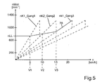
- FIG. 5 shows a transmission map in which linear dependencies of the engine speed nMot on the vehicle speed v are plotted for the various gears of the dual-clutch transmission 14.
- the curve 78 represents the speed nMot of the internal combustion engine 12, which initially corresponds to its idling speed nLL.
- nLL the speed of the internal combustion engine 12
- Both clutches K1, K2 transmit tractive moments of the internal combustion engine, which set the vehicle in motion.
- the engine speed nMot is in this phase by interventions S_mot in the control of the internal combustion engine held a setpoint, which corresponds to one embodiment of the idle speed nLL or slightly higher.
- the speed nMot of the speed nK1_Gang 1 corresponds to the input shaft 28 of the first subtransmission TG1.
- the first clutch K1 can no longer transmit traction torques when the first gear is engaged for speeds v> v1. Instead, it can only transfer pusher moments.
- the clutch K2 initially transmits a tensile torque.
- both clutches K1, K2 are initially operated in slippage as the speed v increases, and the speed nMot of the internal combustion engine 12 is at speeds v> v1 by suitable actuation of the clutches K1, K2 with gears engaged simultaneously in both partial transmissions TG1, TG2 set to a setpoint.
- the adjustment is preferably carried out by a control.
- the clutch K1 transmits a sliding torque in the illustrated course of nMot, while the clutch K2 transmits a traction torque.
- the clutch K1 transmits a traction torque in the course of nMot shown, while the clutch K2 transmits a sliding torque. If the moment of tension predominates, the speed nMot decreases. If the sliding moment prevails, the speed nMot increases.
- the engine speed nMot corresponds to the speed nK1_Gang3 of the input shaft 28 of the first partial transmission TG1, so that no speed difference occurs at the clutch K1.
- the clutch K1 is driven in the illustrated embodiment at this time so that it closes completely at this speed, while the clutch K2 is controlled so that it is completely open. In this case, the complete opening of a clutch does not coincide exactly with the complete closing of the other clutch. It is only essential that at least one of the two clutches K1, K2 is operated in slippage with gears simultaneously engaged in both partial transmissions TG1, TG2, so that the dual-clutch transmission 14th not blocked.
Abstract
Description
Die Erfindung betrifft ein Verfahren zur Steuerung des Triebstrangs eines Kraftfahrzeugs, der ein Doppelkupplungsgetriebe mit einem ersten Teilgetriebe und einer ersten Kupplung sowie mit einem zweiten Teilgetriebe und einer zweiten Kupplung aufweist, wobei der Triebstrang mit zeitgleich im ersten Teilgetriebe eingelegten Gang und im zweiten Teilgetriebe eingelegten Gang und zeitgleich im Schlupf betriebener erster Kupplung und zweiter Kupplung betrieben wird. Die Erfindung betrifft ferner ein zur Durchführung des Verfahrens eingerichtetes Steuergerät.The invention relates to a method for controlling the drivetrain of a motor vehicle having a dual-clutch transmission with a first partial transmission and a first clutch and a second partial transmission and a second clutch, wherein the drive train with simultaneously engaged in the first partial transmission gear and engaged in the second partial transmission gear and simultaneously operated in the slip operated first clutch and second clutch. The invention further relates to a set up for carrying out the method control unit.
Ein solches Verfahren und ein solches Steuergerät ist jeweils aus in Serie gefertigten Kraftfahrzeugen bekannt. Die Aufteilung des Doppelkupplungsgetriebe in ein erstes und in zweites Teilgetriebe, die unabhängig voneinander über die erste, respektive zweite Kupplung mit dem Antriebsmotor des Triebstrangs verbunden werden können, erlaubt ein zugkraftunterbrechungsfreies Wechseln der Übersetzungen. Beim Anfahren treibt der Antriebsmotor das Kraftfahrzeug in der Regel zunächst über die erste Kupplung und das erste Teilgetriebe an. Dabei kann bei offener (zweiter) Kupplung des zweiten Teilgetriebes im zweiten Teilgetriebe bereits der zweite Gang eingelegt werden. Beim Überleiten der Drehmomentübertragung von einer Übertragung über das erste Teilgetriebe zu einer Übertragung über das zweite Teilgetriebe werden beide Kupplungen kurzzeitig gleichzeitig im Schlupf betrieben, wobei die Drehmomentübertragung über die erste Kupplung abnimmt und über die zweite Kupplung zunimmt. Die in dieser Überleitungsphase gleichzeitig über beide Kupplungen übertragenen Drehmomente werden im Doppelkupplungsgetriebe addiert. Nach erfolgter Überleitung ist die zweite Kupplung komplett geschlossen. Nach Abschluss der Überleitung wird das Kraftfahrzeug im zweiten Gang weiter beschleunigt. Aufgrund des Wechsels der Übersetzung ändert sich der Zusammenhang zwischen Motordrehzahl und Fahrgeschwindigkeit. Das Öffnen und Schließen der Kupplungen sowie die sich dabei ergebenden Drehzahländerungen regen Schwingungen des Triebstrangs an.Such a method and such a control unit is known in each case from series-produced motor vehicles. The division of the dual-clutch transmission in a first and in the second partial transmission, which can be connected independently of each other via the first, respectively second clutch with the drive motor of the drive train, allows a change in the transmission without interruption. When starting, the drive motor usually drives the motor vehicle initially via the first clutch and the first partial transmission. In the case of an open (second) clutch of the second subtransmission, the second gear can already be engaged in the second subtransmission. When passing the torque transmission from a transmission via the first partial transmission to a transmission via the second partial transmission, both clutches are briefly operated simultaneously in slippage, whereby the torque transmission via the first clutch decreases and increases via the second clutch. The torques transmitted simultaneously via both clutches in this transfer phase are added together in the dual-clutch gearbox. After successful transfer, the second clutch is completely closed. After completion of the transition, the motor vehicle is accelerated in second gear on. Due to the change in the ratio, the relationship between engine speed and vehicle speed changes. The opening and closing of the clutches and the resulting speed changes stimulate vibrations of the drivetrain.
Beim Fahren mit niedrigen Geschwindigkeiten im untersten Teillastbereich, also mit nur sehr geringer Drehmomentanforderung durch den Fahrer, spielt der Komfort eine größere Rolle als andere Eigenschaften, zum Beispiel als ein sportliches Fahrverhalten. Besonders im Schritttempo-Bereich zwischen etwa 5 und 15 km/h werden Längsschwingungen des Fahrzeugs, die durch die genannten Schaltungen verursacht werden, oder spürbare Rucke, die durch Lastwechsel verursacht werden, oder Vibrationen, die durch Ladungswechsel bei der Füllung von Brennräumen des Antriebsmotors verursacht werden, als störend empfunden.When driving at low speeds in the lowest part-load range, ie with very little torque request by the driver, the comfort plays a greater role than other properties, such as a sporty driving. Especially in the stepping pace range between about 5 and 15 km / h, longitudinal vibrations of the vehicle caused by said circuits or noticeable jerks caused by load changes or vibrations caused by charge changes in the filling of combustion chambers of the drive motor are perceived as disturbing.
So führen zum Beispiel Schub- und Teillast-Schaltungen beim Ausrollen (Anhalten) zu unkomfortablen Längsschwingungen und Zug / Schub-Lastwechseln. Auch ein spätes Öffnen der Kupplung des ersten Ganges kurz vor dem Anhalten führt durch die resultierende Antriebsstrang-Entlastung zu einer spürbaren Veränderung der Längsverzögerung. Gegebenenfalls werden Rückschaltungen sogar mit Zwischengas ausgeführt und erhöhen den Kraftstoffverbrauch.For example, thrust and part load circuits when coasting (stopping) to uncomfortable longitudinal vibrations and train / thrust load changes. Also, a late opening of the clutch of the first gear shortly before stopping leads by the resulting drive train discharge to a noticeable change in the longitudinal deceleration. If necessary, downshifts are even carried out with intermediate gas and increase fuel consumption.
Beim Konstantfahren mit sehr niedrigen Geschwindigkeiten von zum Beispiel 5 km/h- 15 km/h, wie sie typischerweise im Stop and go - Betrieb auftreten, führen Schaltungen zu Geschwindigkeitsänderungen und unkomfortablen Längsschwingungen, die der Fahrer durch Fahrpedalkorrekturen ausgleichen muss. Ferner sind während der Schaltungen durch Massenträgheitseffekte, Momentenänderungen und Übersetzungsänderungen hervorgerufene Ruckeffekte und / oder Beschleunigungseffekte zu spüren. Durch den Drehzahleinfluss verändert sich sowohl das Motormoment, als auch die Motorleistung, wodurch der Fahrer gezwungen wird, den Fahrpedalwinkel zu korrigieren. Häufige Hoch- und Rückschaltungen sind auf Grund der niedrigen Hysterese (Geschwindigkeitsabstand) unerwünscht und doch wahrscheinlich.When driving at very low speeds of, for example, 5 km / h - 15 km / h, as typically occur in stop and go operation, circuits lead to speed changes and uncomfortable longitudinal vibrations, which the driver must compensate by accelerator corrections. Furthermore, during the circuits caused by inertia effects, torque changes and translation changes caused jerking effects and / or acceleration effects. The influence of the speed of rotation changes both the engine torque and the engine power, which forces the driver to correct the accelerator pedal angle. Frequent upshifts and downshifts are undesirable and yet likely due to the low hysteresis (speed distance).
Vor diesem Hintergrund besteht die Aufgabe der Erfindung in der Angabe eines Verfahrens und eines Steuergerätes, mit denen der Fahrkomfort unter den genannten Bedingungen verbessert wird.Against this background, the object of the invention in the specification of a Method and a control unit with which the ride comfort under the conditions mentioned is improved.
Diese Aufgabe wird mit einem Verfahren mit den Merkmalen des Anspruchs 1 sowie mit einem Steuergerät mit den Merkmalen des Anspruchs 9 gelöst.This object is achieved by a method having the features of
Dabei wird jeweils die erste und die zweite Kupplung in aufeinander abgestimmter Weise so angesteuert, dass eine Drehzahl des Verbrennungsmotors einen vorbestimmten Wert annimmt oder beibehält. Mit anderen Worten: Anstelle die eine Kupplung im aktuellen Gang komplett zu schließen und die andere Kupplung komplett zu öffnen, werden beide Kupplungen im Schlupf, bevorzugt im geregelten Schlupf, betrieben, um ein erwünschtes komfortables Fahrverhalten zu erzielen.In each case, the first and the second clutch are controlled in a coordinated manner so that a rotational speed of the internal combustion engine assumes or retains a predetermined value. In other words, instead of completely closing one clutch in the current gear and completely opening the other clutch, both clutches are operated in slip, preferably in regulated slip, in order to achieve a desired comfortable driving behavior.
Durch diese Merkmale wird erreicht, dass sich die Motordrehzahl bei langsamer Fahrt einer Solldrehzahl folgend sanft und ohne ausgeprägte lokale Drehzahlminima und Drehzahlmaxima weich einer Zieldrehzahl angleicht. Die Zieldrehzahl kann beim Anhalten zum Beispiel die Leerlaufdrehzahl sein. Bei permanent geschlossener Kupplung, wie es beim Stand der Technik üblich ist, könnte die Motordrehzahl dagegen speziell bei langsamer Fahrt im 1. und 2. Gang unter eine Zieldrehzahl absinken. Um das zu vermeiden, ist es bekannt, eine Hochschaltung später und die Rückschaltung, zum Beispiel in den ersten Gang, früher erfolgen zu lassen, was den Kraftstoffverbrauch erhöht und mit Komforteinbußen verbunden ist. Die bei der Erfindung erzielten niedrigen Motordrehzahlen von zum Beispiel 700 1/min bis 1200 1/min helfen dagegen, den Kraftstoffverbrauch zu senken.As a result of these features, the engine speed smoothly follows a target rotational speed when driving slowly at a setpoint speed, and without pronounced local rotational speed minima and rotational speed maxima. The target speed may be, for example, the idle speed when stopping. With permanently closed clutch, as is common in the prior art, the engine speed, however, could drop below a target speed, especially at slow speeds in 1st and 2nd gear. To avoid this, it is known to have an upshift later and downshifting, for example to first gear, earlier, which increases fuel consumption and reduces comfort. By contrast, the low engine speeds of, for example, 700 rpm to 1200 rpm achieved in the invention help to reduce fuel consumption.
Weitere Vorteile ergeben sich aus den abhängigen Ansprüchen, der Beschreibung und den beigefügten Figuren.Further advantages will be apparent from the dependent claims, the description and the attached figures.
Es versteht sich, dass die vorstehend genannten und die nachstehend noch zu erläuternden Merkmale nicht nur in der jeweils angegebenen Kombination, sondern auch in anderen Kombinationen oder in Alleinstellung verwendbar sind, ohne den Rahmen der vorliegenden Erfindung zu verlassen.It is understood that the features mentioned above and those yet to be explained not only in the combination specified, but also in other combinations or in isolation, without departing from the scope of the present invention.
Ausführungsbeispiele der Erfindung sind in den Zeichnungen dargestellt und werden in der nachfolgenden Beschreibung näher erläutert. Es zeigen, jeweils in schematischer Form:
- Fig. 1
- das technische Umfeld der Erfindung;
- Fig. 2
- Verläufe verschiedener Betriebsparameter des Triebstrangs aus der
Figur 1 - Fig. 3
- ein Flussdiagramm als Ausführungsbeispiel eines erfindungsgemäßen Verfahrens;
- Fig. 4
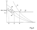
- einen geglätteten Verlauf der Drehzahl des Verbrennungsmotors, wie er sich beim Gegenstand der hier vorliegenden Erfindung beim Anhalten des Fahrzeugs einstellt; und
- Fig. 5
- einen Verlauf der Motordrehzahl bei einem Ausführungsbeispiel der Erfindung in einem Übersetzungskennfeld, in dem lineare Abhängigkeiten der Motordrehzahl nMot von der Fahrgeschwindigkeit v für die verschiedenen Gänge des Doppelkupplungsgetriebes aufgetragen sind.
- Fig. 1
- the technical environment of the invention;
- Fig. 2
- Gradients of various operating parameters of the drive train from the
FIG. 1 in a prior art control of the driveline over time when stopping the vehicle; - Fig. 3
- a flowchart as an embodiment of a method according to the invention;
- Fig. 4
- a smoothed course of the speed of the internal combustion engine, as it adjusts the subject of the present invention when stopping the vehicle; and
- Fig. 5
- a curve of the engine speed in an embodiment of the invention in a transmission map in which linear dependencies of the engine speed nMot of the vehicle speed v for the different gears of the dual clutch transmission are plotted.
Im Einzelnen zeigt die
Das Doppelkupplungsgetriebe 14 weist ein erstes Teilgetriebe TG1 und ein zweites Teilgetriebe TG2 auf. Ein Drehmomentfluss zwischen einer Eingangswelle 28 des ersten Teilgetriebes TG1 und einer Kurbelwelle 30 des Verbrennungsmotors 12 erfolgt über eine erste steuerbare Kupplung K1. Ein Drehmomentfluss zwischen einer Eingangswelle 32 des zweiten Teilgetriebes TG2 und der Kurbelwelle 30 des Verbrennungsmotors 12 erfolgt über eine zweite steuerbare Kupplung K2. Das erste Teilgetriebe TG1 stellt in einer Ausgestaltung Übersetzungsstufen (Gänge) mit ungeradzahliger Nummerierung wie den ersten Gang, den dritten Gang und so weiter bereit, während das zweite Teilgetriebe TG2 die Übersetzungsstufen (Gänge) mit geradzahliger Nummerierung wie den zweiten Gang, den vierten Gang und so weiter bereitstellt.The dual-
Sowohl eine Hauptwelle 34 des ersten Teilgetriebes TG1 als auch eine Hauptwelle 36 des zweiten Teilgetriebes TG2 ist drehfest mit der Welle 20 verbunden. Die Wellen 34 und 36 drehen sich daher mit der gleichen Drehzahl, die bei Geradeausfahrt des Kraftfahrzeugs ohne Schlupf an den Antriebsrädern 16, 18 linear von der Drehzahl der Antriebsräder 16, 18 und damit linear von der Fahrgeschwindigkeit v des Fahrzeugs abhängt. In der schematischen Darstellung der
Ein Steuergerät 40 steuert in der Ausgestaltung der
Zur Steuerung des Triebstranges 10 verarbeitet das Steuergerät 40 Signale einer Vielzahl von Sensoren, in denen sich Betriebsparameter des Triebstrangs 10 abbilden. In Verbindung mit der Erfindung sind dabei insbesondere die folgenden Betriebsparameter von Bedeutung: Ein Fahrpedalwinkel Wped, der von einem Fahrerwunschgeber 42 bereitgestellt wird und in dem sich eine Drehmomentanforderung durch den Fahrer abbildet, eine Drehzahl nMot der Kurbelwelle 30 des Verbrennungsmotors 12, die von einem Drehzahlsensor 43 erfasst wird und eine Fahrgeschwindigkeit v, die von einem Fahrgeschwindigkeitsgeber 44 erfasst wird. Der Fahrgeschwindigkeitsgeber 44 ist in einer Ausgestaltung als Drehzahlsensor realisiert, der eine Drehzahl am Ausgang des Doppelkupplungsgetriebes 14, also eine Drehzahl von einer der Wellen 34, 36 oder 20 erfasst. Alternativ oder ergänzend wird ein Drehzahlsignal an einem oder mehreren der Räder 16, 18 erfasst, zum Beispiel mit Hilfe der Sensorik eines Anti-Blockier-Systems.To control the
Bei Kenntnis der in den Teilgetrieben TG1 und TG2 jeweils eingestellten Übersetzungen ergibt sich die Drehzahl nK1 der Eingangswelle 28 des ersten Teilgetriebes TG1 und die Drehzahl nK2 der Eingangswelle 32 des zweiten Teilgetriebes TG2 jeweils als lineare Funktion der Fahrgeschwindigkeit v.With knowledge of the translations set in the partial transmissions TG1 and TG2 respectively, the rotational speed nK1 of the
In Abhängigkeit von diesen Betriebsparametern des Triebstrangs 10 und gegebenenfalls in Abhängigkeit von weiteren Betriebsparametern, insbesondere in Abhängigkeit von Betriebsparametern des Verbrennungsmotors 12, bildet das Steuergerät 40 Stellsignale S_Mot, S_K1, S_K2, S_TG1 und S_TG2. Dabei dient das Stellsignal S_Mot zur Einstellung eines Drehmomentes des Verbrennungsmotors 12. Das Stellsignal S_TG1 dient zum Einlegen eines Ganges im ersten Teilgetriebe TG1 und damit zum Einstellen seiner Übersetzung. Das Stellsignal S_TG2 dient analog zum Einstellen einer Übersetzung im zweiten Teilgetriebe TG2. Mit dem Stellsignal S_K1 wird der Drehmomentfluss über die erste Kupplung K1 gesteuert. Analog wird der Drehmomentfluss über die zweite Kupplung K2 mit dem Stellsignal S_K2 gesteuert.As a function of these operating parameters of the
Der Zusammenhang der Ansteuersignale S_K1, S_K2 mit dem jeweils über jede der beiden Kupplungen K1, K2 bei bestimmten Drehzahlunterschieden übertragenen Drehmoment ist bevorzugt in Form von Kennlinien oder Kennfeldern im Steuergerät 40 abgelegt. Dies ist Stand der Technik. Die Drehzahlunterschiede sind im Steuergerät 40 durch Auswertung der Drehzahlwerte nMot und nK1, nK2 ebenfalls bekannt. Bekannt ist auch das Motormoment, das vom Steuergerät 40 aus Betriebskenngrößen des Verbrennungsmotors 12 laufend berechnet wird, da moderne Motorsteuerungen sämtliche Stellgrößen auf der Basis von Drehmomentanforderungen bestimmen, die zum Beispiel in Abhängigkeit von dem Fahrpedalwinkel Wped berechnet werden.The relationship of the drive signals S_K1, S_K2 with the torque transmitted in each case via each of the two clutches K1, K2 at specific speed differences is preferably in the form of characteristic curves or characteristic diagrams in the
Das Steuergerät 40 ermittelt aus dem Vorzeichen des Drehzahlunterschiedes an jeder der Kupplung K1, K2 die Richtung des jeweils übertragenen Drehmoments und aus dem Drehzahlunterschied und dem sich letztlich im Anpressdruck der Kupplungsreibflächen abbildenden Ansteuersignal S_K1, S_K2 den Wert des über jede der beiden Kupplungen K1, K2 übertragenen Drehmoments.From the sign of the speed difference at each of the clutches K1, K2, the
Daher kann das Steuergerät 40 den Drehmomentfluss über beide Kupplungen K1, K2 in gesteuerter Weise verteilen und damit Richtung und Ausmaß des resultierenden gesamten Drehmomentflusses steuern, um die Motordrehzahl nMot durch aufeinander abgestimmtes Ansteuern beider Kupplungen K1, K2 auf einen Sollwert oder Sollwertverlauf über der Zeit oder über der Fahrgeschwindigkeit v einzustellen.Therefore, the
Im Übrigen ist das Steuergerät 40 oder ein entsprechender Verbund von Steuergeräten dazu eingerichtet, insbesondere dazu programmiert, das erfindungsgemäße Verfahren oder eine seiner Ausgestaltungen durchzuführen. Dabei wird unter einer Durchführung eine Steuerung der hier beschriebenen Verfahrensabläufe verstanden.Incidentally, the
Bis zum Zeitpunkt t0 verzögert das Fahrzeug im dritten Gang bei geschlossener Kupplung K1. Die Kupplung K2 ist offen. Die Motordrehzahl nMot entspricht dort der Drehzahl nK1_Gang 3. Parallel wird bei offener Kupplung K2 der zweite Gang im zweiten Teilgetriebe TG2 eingelegt. Zwischen den Zeitpunkten t0 und t1 wird die erste Kupplung K1 zunehmend geöffnet und die Kupplung K2 zunehmend geschlossen, bis zum Zeitpunkt t1 die Kupplung K1 ganz offen und die Kupplung K2 ganz geschlossen ist. Die Drehzahl nMot steigt entsprechend bei schlupfenden Kupplungen K1, K2 bis zum Zeitpunkt t1 an, um anschließend bei geschlossener Kupplung K2 und offener Kupplung K1 bei weiterer Verzögerung des Fahrzeugs wieder abzufallen.Until the time t0, the vehicle decelerates in third gear with the clutch K1 closed. The clutch K2 is open. The engine speed nMot corresponds there to the speed nK1_Gang 3. In parallel, with the clutch K2 open, the second gear is engaged in the second partial transmission TG2. Between the times t0 and t1, the first clutch K1 is increasingly opened and the clutch K2 increasingly closed, until the time t1, the clutch K1 completely open and the clutch K2 is completely closed. The speed nMot accordingly increases with slipping clutches K1, K2 until the time t1, in order subsequently to drop again when the clutch K2 and the open clutch K1 are closed when the vehicle decelerates further.
Bei offener Kupplung K1 wird nach dem Zeitpunkt t1 der erste Gang im ersten Teilgetriebe TG1 eingelegt. Zwischen den Zeitpunkten t2 und t3 wird die zweite Kupplung K2 zunehmend geöffnet und die erste Kupplung K1 zunehmend geschlossen. Dadurch steigt die Drehzahl nMot des Verbrennungsmotors 12 auf einen durch die Kurve 47 vorgegebenen Wert an. Anschließend fällt sie bei weiterer Verzögerung des Fahrzeugs wieder ab, bis zum Zeitpunkt t4 der Wert der Leerlaufdrehzahl erreicht wird.When the clutch K1 is open, after the time t1, the first gear is engaged in the first partial transmission TG1. Between times t2 and t3, the second clutch K2 is increasingly opened and the first clutch K1 increasingly closed. As a result, the rotational speed nMot of the
Um zu verhindern, dass die Drehzahl nMot die Leerlaufdrehzahl des Verbrennungsmotors unterschreitet, wird die Kupplung K1 zum Zeitpunkt t4 geöffnet. Anschließend wird die Drehzahl nMot durch eine bekannte Leerlaufdrehzahlregelung auf einem konstanten Wert gehalten. Der vor dem Zeitpunkt t4 im Verlauf 48 der Drehzahl nMot sichtbare Wechsel zwischen lokalen Drehzahlminima und lokalen Drehzahlmaxima entsteht dadurch, dass die Drehzahl des Verbrennungsmotors 12 zwischen den Zeitpunkten t0 und t1 sowie t2 und t3 jeweils auf Kosten der kinetischen Energie des Fahrzeugs angehoben wird. Die Bremswirkung des Verbrennungsmotors 12 variiert deshalb und regt die Schwingungen im Triebstrang 10 an, die sich in den unerwünschten Längsschwingungen des Fahrzeugs abbilden. Analog stellt der Ruck beim Öffnen der Kupplung K1 zum Zeitpunkt t4 eine Störung dar, die Schwingungen anregen kann oder als Ruck spürbar ist.In order to prevent the rotational speed nMot from falling below the idling speed of the internal combustion engine, the clutch K1 is opened at the time t4. Subsequently, the rotational speed nMot is maintained at a constant value by a known idle speed control. The change visible before time t4 in the
Aus diesem Hauptprogramm HP(B = 0) heraus wird wiederholt ein Schritt 52 erreicht, in dem Betriebsparameter BP des Triebstrangs 10 eingelesen werden, die für eine Aktivierung der hier vorgestellten Komfort-orientierten Steuerung des Triebstrangs ausgewertet werden. Einzelheiten der Komfort-orientierten Steuerung werden weiter unten unter Bezug auf die
Die Auswertung wird in der
Wenn die Auswertung im Schritt 54 ergibt, dass die Komfort-orientierte Steuerung nicht durchgeführt werden soll, wird B auf den Wert B = 0 gesetzt. Dann wird die Abfrage im anschließenden Schritt 56 verneint wird und das Hauptprogramm HP(B = 0) im Schritt 50 weiter abgearbeitet. Das bedeutet, dass der Triebstrang 10 in der aus dem Stand der Technik bekannten Weise (vergleiche
Ergibt die Auswertung im Schritt 54 dagegen, dass eine Komfort-orientierte Steuerung der Kupplungen K1, K2 erfolgen soll, wird B auf den Wert B = 1 gesetzt. B wird in einer Ausgestaltung auf 1 gesetzt, wenn das Fahrzeug mit geringer Drehmomentanforderung durch den Fahrer, also mit geringem Pedalwinkel Wped und niedriger Geschwindigkeit in einem niedrigen Gang, zum Beispiel im ersten oder zweiten Gang, bewegt wird. In einer Ausgestaltung wird dazu überprüft, ob der Fahrpedalwinkel Wped kleiner als ein unterer Schwellenwert Wped_low und gleichzeitig sowohl die Motordrehzahl nMot kleiner als ein Schwellenwert nMot_Grenz als auch die Fahrgeschwindigkeit v kleiner als ein Schwellenwert v_Grenz ist. In einer weiteren Ausgestaltung ist der Schwellenwert nMot_Grenz und/oder der Schwellenwert v_Grenz von einem Modulationsfaktor MF abhängig, in dem sich die Fahrbahnneigung in Fahrtrichtung abbildet und der zum Beispiel von einem Neigungssensor bereitgestellt wird: 
Typische Werte sind, ohne dass die Erfindung auf diese Werte beschränkt sein soll: Wped_Grenz < 10 % des maximalen Pedalwinkels, 500 min-1 < Leerlaufdrehzahl < nMot_Grenz < (900 min-1 in der Ebene, 1200 min-1 am Berg).Typical values are, without the invention being restricted to these values: Wped_Grenz <10% of the maximum pedal angle, 500 min -1 <idle speed <nMot_Grenz <(900 min -1 in the plane, 1200 min -1 on the mountain).
Wenn diese Bedingungen erfüllt sind, wird die Abfrage im anschließenden Schritt 56 bejaht und das Programm verzweigt in den Schritt 58, in dem ein modifiziertes Hauptprogramm HP(B = 1) zur Steuerung des Triebstrangs 10 in Komfort-orientierter Weise abgearbeitet wird.If these conditions are fulfilled, the query in the
Aus dem Schritt 58 wird wiederholt der Schritt 60 erreicht, in dem Betriebsparameter BP des Triebstrangs 10 eingelesen werden, die für eine Deaktivierung der hier vorgestellten Komfort-orientierten Steuerung des Triebstrangs ausgewertet werden. Die Auswertung wird in der
In einer Ausgestaltung wird B im Schritt 62 auf 0 gesetzt, wenn die Kupplung K1 im ersten Gang oder die Kupplung K2 im zweiten Gang nicht mehr schlupft, also keine Differenz zwischen Motordrehzahl nMot und der Drehzahl der Eingangswelle des zugehörigen Teilgetriebes mehr auftritt, und gleichzeitig die Fahrzeuggeschwindigkeit v einen Schwellenwert v_Grenz überschreitet oder oberhalb dieses Schwellenwerts liegt. Der Schwellenwert ist bevorzugt kleiner als 20 km /h und ist in einer Ausgestaltung von dem Modulationsfaktor MF so abhängig, dass sich am Berg ein höherer Grenzwert ergibt als in der Ebene.In one embodiment, B is set to 0 in
Alternativ wird B auf 0 gesetzt, wenn die Drehmomentanforderung Wped durch den Fahrer einen Schwellenwert Wped_Grenz_Zug überschreitet und die zu schließende Kupplung nicht mehr schlupft. Auch hier sieht eine Ausgestaltung vor, dass der Schwellenwert Wped_Grenz_Zug von der Fahrgeschwindigkeit v und dem Modulationsfaktor so abhängig ist, dass er mit zunehmenden Werten von v und/oder MF ebenfalls zunimmt. Ohne Beschränkung der Allgemeinheit liegen Werte für Wped_Grenz_Zug bevorzugt zwischen 50 % und 70 % des maximalen Pedalwinkels.Alternatively, B is set to 0 when the driver's torque request Wped exceeds a threshold Wped_Grenz_Zug and the clutch to be engaged no longer slips. Here, too, an embodiment provides that the threshold value Wped_Grenz_Zug is dependent on the driving speed v and the modulation factor so that it also increases with increasing values of v and / or MF. Without limitation of generality, values for Wped_Grenz_Zug are preferably between 50% and 70% of the maximum pedal angle.
Eine weitere Ausgestaltung sieht vor, dass B auf 0 gesetzt wird, wenn der Fahrer manuell vom zweiten Gang in den ersten Gang zurückschaltet. Dann wird die erste Kupplung K1 geschlossen. Wenn sie nicht mehr schlupft, und die Motordrehzahl nMot einen gegebenenfalls noch um einen Hysterese-Offset vergrößerten Schwellenwert nMot_Grenz (v, MF) überschreitet, wird erfolgt das Rücksetzen von B = 1 auf B = 0. Ohne Beschränkung der Allgemeinheit liegt der Hysterese-Offset in der Größenordnung von 50 min-1.Another embodiment provides that B is set to 0 if the driver manually switches back from second gear to first gear. Then, the first clutch K1 is closed. If it no longer slips and the engine speed nMot exceeds a threshold value nMot_Grenz (v, MF), which may be increased by a hysteresis offset, the reset from B = 1 to B = 0 takes place. Without hindering the generality, the hysteresis offset is present in the order of 50 min-1.
Ab dem Zeitpunkt t0 des Erreichens des Schwellenwertes nMot_Grenz wird die erste Kupplung K1 sukzessive geöffnet und die zweite Kupplung K2 sukzessive geschlossen. Im Unterschied zum Stand der Technik erfolgt das Öffnen der Kupplung K1 und das Schließen der Kupplung K2 in aufeinander abgestimmter Weise so, dass sich die Motordrehzahl nMot monoton fallend der Leerlaufdrehzahl nLL des Verbrennungsmotors 12 als Zieldrehzahl annähert. Dabei wird die Drehzahl nMot alternativ oder ergänzend zu Eingriffen in die Steuerung des Verbrennungsmotors 12 durch aufeinander abgestimmte Steuerung der Drehmomentflüsse über beide Kupplungen K1, K2 eingestellt. Bis zum Zeitpunkt t0 war die Kupplung K2 offen und übertrug damit kein Drehmoment, während die Kupplung K1 bei verzögerndem Fahrzeug im Schiebebetrieb ein Schiebemoment überträgt, mit dem der Verbrennungsmotor 12 durch die kinetische Energie des verzögernden Fahrzeuges angetrieben wird.From the time t0 of reaching the threshold nMot_Grenz becomes the first Coupling K1 successively opened and the second clutch K2 successively closed. In contrast to the prior art, the opening of the clutch K1 and the closing of the clutch K2 takes place in a coordinated manner so that the engine speed nMot decreases monotonically decreasing the idle speed nLL of the
Das allmähliche Öffnen der Kupplung K1 ab dem Zeitpunkt t0 erlaubt einen Schlupf an der Kupplung K1. Das parallel erfolgende allmählich schließende Kupplung K2 verlagert die Übertragung des den Verbrennungsmotor 12 antreibenden Schiebemoments auf die Kupplung K2. Im Ergebnis führt das dazu, dass die Motordrehzahl nMot nach dem Zeitpunkt t0 zwischen Werten auf der Kurve 68 des zweiten Ganges und der Kurve 66 des dritten Ganges liegt. Die Motordrehzahl nMot ist für den dritten Gang zu hoch und für den zweiten Gang zu niedrig. Das heißt, dass die Motordrehzahl nMot durch schließendes Ansteuern der Kupplung K1 des dritten Gangs verringert und durch schließendes Ansteuern der Kupplung K2 des zweiten Gangs erhöht werden kann.The gradual opening of the clutch K1 from the time t0 allows a slip on the clutch K1. The parallel gradually closing clutch K2 shifts the transmission of the
Durch schließende Ansteuerung von jeweils einer der beiden Kupplungen K1, K2 kann die Drehzahl nMot damit erhöht oder verringert werden. Die Ansteuerung erfolgt dabei in einer Ausgestaltung bevorzugt in geregelter Weise. Dazu wird der Istwert der Motordrehzahl nMot mit einem Sollwert verglichen und aus der Regelabweichung werden Stellgrößen S_K1 und S_K2 gebildet, mit denen die Drehmomentübertragung über die Kupplungen K1 und K2 individuell gesteuert wird.By closing control of one of the two clutches K1, K2, the speed nMot can thus be increased or decreased. The control is carried out in one embodiment preferably in a controlled manner. For this purpose, the actual value of the engine speed nMot is compared with a desired value and the control deviation S_K1 and S_K2 are formed with which the torque transmission via the clutches K1 and K2 is controlled individually.
In der
Zum Zeitpunkt t2 durchläuft die Drehzahl nMot die Kurve 68. Zu diesem Zeitpunkt überträgt die kurzzeitig geschlossene Kupplung K2 vorübergehend das ganze Schiebemoment, während die Kupplung K1 vorübergehend ganz geöffnet wird. Bei geöffneter Kupplung K1 wird der erste Gang eingelegt. Ab jetzt wirkt ein Schließen der Kupplung K1 nMot- erhöhend und ein Geschlossenhalten der Kupplung K2 nMotverringernd. Analog zum Vorgehen zwischen den Zeitpunkten t0 und t2 wird im Folgenden die Motordrehzahl nMot durch entsprechendes Ansteuern der Kupplungen K1, K2 monoton fallend in die Zieldrehzahl überführt.At time t2, the speed nMot passes through the
Die Zieldrehzahl in Form der Leerlaufdrehzahl nLL wird zum Zeitpunkt t4 erreicht, in dem die Kurve 70 den Wert der Zieldrehzahl schneidet. Um zu verhindern, dass die Motordrehzahl nMot unter die Zieldrehzahl sinkt, wird nicht nur die zweite Kupplung K2, sondern auch die erste Kupplung K1 bei der Annäherung an den Schnittpunkt 76 zunehmend geöffnet.The target speed in the form of the idle speed nLL is reached at time t4, in which the
Beim Erreichen der Geschwindigkeit v1 entspricht die Drehzahl nMot der Drehzahl nK1_Gang 1 der Eingangswelle 28 des ersten Teilgetriebes TG1. Bei dem angestrebten, von der Fahrzeuggeschwindigkeit v abhängigen Verlauf der Motordrehzahl nMot kann die erste Kupplung K1 bei eingelegtem ersten Gang für Geschwindigkeiten v > v1 keine Zugmomente mehr übertragen. Stattdessen kann sie nur noch Schiebemomente übertragen. Die Kupplung K2 überträgt dagegen zunächst weiter ein Zugmoment. Ähnlich wie beim Anhalten werden beide Kupplungen K1, K2 bei steigender Geschwindigkeit v zunächst weiter im Schlupf betrieben und die Drehzahl nMot des Verbrennungsmotors 12 wird bei Geschwindigkeiten v > v1 durch geeignete Ansteuerung der Kupplungen K1, K2 bei gleichzeitig in beiden Teilgetrieben TG1, TG2 eingelegten Gängen auf einen Sollwert eingestellt. Die Einstellung erfolgt bevorzugt durch eine Regelung.When the speed v1 is reached, the speed nMot of the
Im Geschwindigkeitsbereich v1 < v < v2 überträgt die Kupplung K1 beim dargestellten Verlauf von nMot ein Schiebemoment, während die Kupplung K2 ein Zugmoment überträgt. Im Geschwindigkeitsbereich v2 < v < v3 überträgt die Kupplung K1 beim dargestellten Verlauf von nMot ein Zugmoment, während die Kupplung K2 ein Schiebemoment überträgt. Wenn das Zugmoment überwiegt, sinkt die Drehzahl nMot. Wenn das Schiebemoment überwiegt, steigt die Drehzahl nMot. Beim Erreichen der Geschwindigkeit v3 entspricht die Motordrehzahl nMot der Drehzahl nK1_Gang3 der Eingangswelle 28 des ersten Teilgetriebes TG1, so dass an der Kupplung K1 kein Drehzahlunterschied auftritt. Die Kupplung K1 wird in der dargestellten Ausgestaltung zu diesem Zeitpunkt so angesteuert dass sie bei dieser Geschwindigkeit komplett schließt, während die Kupplung K2 so angesteuert wird, dass sie komplett geöffnet ist. Dabei muss das komplette Öffnen der einen Kupplung nicht ganz genau mit dem kompletten Schließen der anderen Kupplung zusammenfallen. Wesentlich ist nur, dass bei gleichzeitig in beiden Teilgetrieben TG1, TG2 eingelegten Gängen wenigstens eine der beiden Kupplungen K1, K2 im Schlupf betrieben wird, damit das Doppelkupplungsgetriebe 14 nicht blockiert.In the speed range v1 <v <v2, the clutch K1 transmits a sliding torque in the illustrated course of nMot, while the clutch K2 transmits a traction torque. In the speed range v2 <v <v3, the clutch K1 transmits a traction torque in the course of nMot shown, while the clutch K2 transmits a sliding torque. If the moment of tension predominates, the speed nMot decreases. If the sliding moment prevails, the speed nMot increases. When the speed v3 is reached, the engine speed nMot corresponds to the speed nK1_Gang3 of the
Ab der Geschwindigkeit v3, die bei der Darstellung der
Die glatten nMot-Verläufe 64 in der
Claims (10)
Applications Claiming Priority (1)
| Application Number | Priority Date | Filing Date | Title |
|---|---|---|---|
| DE102008006194A DE102008006194A1 (en) | 2008-01-26 | 2008-01-26 | Method and control unit for controlling a drive train, which has a dual-clutch transmission |
Publications (2)
| Publication Number | Publication Date |
|---|---|
| EP2083198A2 true EP2083198A2 (en) | 2009-07-29 |
| EP2083198A3 EP2083198A3 (en) | 2011-07-20 |
Family
ID=40651348
Family Applications (1)
| Application Number | Title | Priority Date | Filing Date |
|---|---|---|---|
| EP08018976A Withdrawn EP2083198A3 (en) | 2008-01-26 | 2008-10-30 | Method and control unit for controlling a power train that has a double clutch |
Country Status (4)
| Country | Link |
|---|---|
| US (1) | US20090192018A1 (en) |
| EP (1) | EP2083198A3 (en) |
| JP (1) | JP4943461B2 (en) |
| DE (1) | DE102008006194A1 (en) |
Cited By (4)
| Publication number | Priority date | Publication date | Assignee | Title |
|---|---|---|---|---|
| WO2012019586A1 (en) * | 2010-08-12 | 2012-02-16 | Schaeffler Technologies Gmbh & Co. Kg | Method for operating an automated dual-clutch transmission |
| DE102011000957A1 (en) * | 2011-02-28 | 2012-08-30 | Dr. Ing. H.C. F. Porsche Aktiengesellschaft | Method for switching a semi-automatic powershift transmission |
| AT512160A4 (en) * | 2011-11-03 | 2013-06-15 | Avl List Gmbh | METHOD FOR SWITCHING A DOUBLE CLUTCH GEARBOX |
| US10161497B2 (en) | 2012-06-22 | 2018-12-25 | Schaefler Technologies Ag & Co. Kg | Method for avoiding or reducing chatter vibrations |
Families Citing this family (9)
| Publication number | Priority date | Publication date | Assignee | Title |
|---|---|---|---|---|
| JP5570420B2 (en) * | 2007-09-06 | 2014-08-13 | ルーク ラメレン ウント クツプルングスバウ ベタイリグングス コマンディートゲゼルシャフト | Control method of dual clutch transmission |
| DE102008043385B4 (en) * | 2008-11-03 | 2020-10-15 | Zf Friedrichshafen Ag | Method for determining the synchronization point of an automated dual clutch transmission |
| DE102010011887A1 (en) * | 2010-03-18 | 2011-09-22 | Dr. Ing. H.C. F. Porsche Aktiengesellschaft | Method for controlling a drive train of a motor vehicle with automated clutch |
| US8308609B2 (en) | 2010-06-14 | 2012-11-13 | Ford Global Technologies, Llc | Power-off downshift engagement dampening |
| US8332111B2 (en) | 2010-11-01 | 2012-12-11 | Ford Global Technologies, Llc | Dual clutch driveline twist control |
| JP5548599B2 (en) * | 2010-12-02 | 2014-07-16 | ジヤトコ株式会社 | Coast stop vehicle and control method thereof |
| FR3004772B1 (en) * | 2013-04-23 | 2015-05-01 | Peugeot Citroen Automobiles Sa | POWERTRAIN AND METHOD FOR CONTROLLING THE GEARBOX FOR PROCESSING ACYCLISMS |
| DE102013104870B4 (en) * | 2013-05-13 | 2022-02-17 | Dr. Ing. H.C. F. Porsche Aktiengesellschaft | Method for operating a dual clutch transmission and control unit for carrying out such a method |
| GB2522870B (en) * | 2014-02-06 | 2018-02-07 | Jaguar Land Rover Ltd | Traction control method comprising two modulated clutches |
Citations (6)
| Publication number | Priority date | Publication date | Assignee | Title |
|---|---|---|---|---|
| DE19939334A1 (en) * | 1999-08-19 | 2001-03-08 | Daimler Chrysler Ag | Method for shifting double-clutch gearbox without tractive force interruption has two lay shafts connected to output shaft through shiftable gear stages and associated with friction clutch for connection to drive motor |
| WO2004033246A2 (en) * | 2002-10-04 | 2004-04-22 | Luk Lamellen Und Kupplungsbau Beteiligungs Kg | Method for controlling gear-shifting processes of a powershift gearbox and corresponding powershift gearbox |
| EP1450074A2 (en) * | 2003-02-21 | 2004-08-25 | BorgWarner, Inc. | Method of controlling a dual clutch transmission |
| EP1507103A1 (en) * | 2003-08-14 | 2005-02-16 | Getrag Ford Transmissions GmbH | Method for shifting dual clutches |
| DE102005006556A1 (en) * | 2004-02-17 | 2005-09-08 | Volkswagen Ag | Clutches` actuating method for motor vehicle, involves triggering clutches during start of motor vehicle, such that clutches simultaneously and continuously transmit torque between drive shaft and output shaft |
| WO2007124710A1 (en) * | 2006-04-28 | 2007-11-08 | Luk Lamellen Und Kupplungsbau Beteiligungs Kg | Method and device for adapting the control of the clutches of a double clutch gear |
Family Cites Families (6)
| Publication number | Priority date | Publication date | Assignee | Title |
|---|---|---|---|---|
| DE19631983C1 (en) * | 1996-08-08 | 1998-02-12 | Volkswagen Ag | Method for shifting a double clutch transmission and double clutch transmission with synchronizing device |
| DE10156940A1 (en) * | 2001-11-20 | 2003-05-28 | Zf Sachs Ag | Method for starting a motor vehicle having a powershift transmission and a double or multiple clutch with high acceleration |
| JP2003278808A (en) * | 2002-03-25 | 2003-10-02 | Aisin Seiki Co Ltd | Automatic transmission |
| DE10218186A1 (en) * | 2002-04-24 | 2003-11-13 | Zahnradfabrik Friedrichshafen | Method for controlling a starting process with a double clutch transmission |
| DE102004007160A1 (en) * | 2004-02-12 | 2005-08-25 | Volkswagen Ag | Process to achieve smooth automotive acceleration while changing gear by regulation of clutch speed within a defined range |
| JP4849982B2 (en) * | 2006-07-18 | 2012-01-11 | ジヤトコ株式会社 | Shift control device and method for automatic transmission |
-
2008
- 2008-01-26 DE DE102008006194A patent/DE102008006194A1/en not_active Ceased
- 2008-10-30 EP EP08018976A patent/EP2083198A3/en not_active Withdrawn
-
2009
- 2009-01-20 JP JP2009009479A patent/JP4943461B2/en not_active Expired - Fee Related
- 2009-01-26 US US12/359,363 patent/US20090192018A1/en not_active Abandoned
Patent Citations (6)
| Publication number | Priority date | Publication date | Assignee | Title |
|---|---|---|---|---|
| DE19939334A1 (en) * | 1999-08-19 | 2001-03-08 | Daimler Chrysler Ag | Method for shifting double-clutch gearbox without tractive force interruption has two lay shafts connected to output shaft through shiftable gear stages and associated with friction clutch for connection to drive motor |
| WO2004033246A2 (en) * | 2002-10-04 | 2004-04-22 | Luk Lamellen Und Kupplungsbau Beteiligungs Kg | Method for controlling gear-shifting processes of a powershift gearbox and corresponding powershift gearbox |
| EP1450074A2 (en) * | 2003-02-21 | 2004-08-25 | BorgWarner, Inc. | Method of controlling a dual clutch transmission |
| EP1507103A1 (en) * | 2003-08-14 | 2005-02-16 | Getrag Ford Transmissions GmbH | Method for shifting dual clutches |
| DE102005006556A1 (en) * | 2004-02-17 | 2005-09-08 | Volkswagen Ag | Clutches` actuating method for motor vehicle, involves triggering clutches during start of motor vehicle, such that clutches simultaneously and continuously transmit torque between drive shaft and output shaft |
| WO2007124710A1 (en) * | 2006-04-28 | 2007-11-08 | Luk Lamellen Und Kupplungsbau Beteiligungs Kg | Method and device for adapting the control of the clutches of a double clutch gear |
Cited By (6)
| Publication number | Priority date | Publication date | Assignee | Title |
|---|---|---|---|---|
| WO2012019586A1 (en) * | 2010-08-12 | 2012-02-16 | Schaeffler Technologies Gmbh & Co. Kg | Method for operating an automated dual-clutch transmission |
| US9243688B2 (en) | 2010-08-12 | 2016-01-26 | Schaeffler Technologies AG & Co. KG | Method for operating an automated dual-clutch transmission |
| DE102011000957A1 (en) * | 2011-02-28 | 2012-08-30 | Dr. Ing. H.C. F. Porsche Aktiengesellschaft | Method for switching a semi-automatic powershift transmission |
| AT512160A4 (en) * | 2011-11-03 | 2013-06-15 | Avl List Gmbh | METHOD FOR SWITCHING A DOUBLE CLUTCH GEARBOX |
| AT512160B1 (en) * | 2011-11-03 | 2013-06-15 | Avl List Gmbh | METHOD FOR SWITCHING A DOUBLE CLUTCH GEARBOX |
| US10161497B2 (en) | 2012-06-22 | 2018-12-25 | Schaefler Technologies Ag & Co. Kg | Method for avoiding or reducing chatter vibrations |
Also Published As
| Publication number | Publication date |
|---|---|
| JP2009174717A (en) | 2009-08-06 |
| JP4943461B2 (en) | 2012-05-30 |
| DE102008006194A1 (en) | 2009-08-06 |
| US20090192018A1 (en) | 2009-07-30 |
| EP2083198A3 (en) | 2011-07-20 |
Similar Documents
| Publication | Publication Date | Title |
|---|---|---|
| EP2083198A2 (en) | Method and control unit for controlling a power train that has a double clutch | |
| EP1439087B1 (en) | Method for adjusting and controlling engine and clutch torque during gear shifting of an automated or dual clutch transmission | |
| EP0670789B1 (en) | Method of controlling the output torque of an automatic transmission | |
| DE10221701B4 (en) | Control method for motor vehicles with automated clutch device | |
| EP2125473B1 (en) | Method for operating an automatic transmission | |
| DE102004058206B4 (en) | Delay control device and deceleration control method for a vehicle | |
| EP1564446B1 (en) | Method and device to control a gear change in a parallel shifting vehicle transmission | |
| EP2619482B1 (en) | Method for controlling shifts in a vehicle transmission | |
| EP2504211B1 (en) | Method and device for operating a hybrid vehicle | |
| DE19709417A1 (en) | Control apparatus for torque transmitting system and automated transmission of motor vehicle | |
| DE102008009135A1 (en) | Method for controlling drive train of motor vehicle, involves detecting internal combustion engine-sided speed of coupling and change speed gearbox sided speed of coupling | |
| DE102016120396A1 (en) | Shift control system for an automatic transmission | |
| DE102013021441A1 (en) | Method for operating vehicle, involves coupling or uncoupling main engine with transmission by clutch, where slip of clutch is adjusted at zero-load demand on main engine in response to drag torque demand in more than two steps | |
| DE102020115131A1 (en) | Dual clutch control method and dual clutch transmission | |
| DE102011018887A1 (en) | Method for controlling drive train of motor vehicle, involves determining and controlling coupling torque to be transmitted on friction clutch, and determining wheel slip of driven wheels against road corresponding to wheel speed | |
| EP1382479B1 (en) | Method for driving off for a vehicle drive system containing a double clutch | |
| DE102008046843B4 (en) | Method for controlling an internal combustion engine in conjunction with an automated friction coupling as a starting element | |
| DE102009045507A1 (en) | Method for actuating transmission device of vehicle drive train during presence of transmission control side requirement for switching, involves monitoring current operating condition of vehicle drive train | |
| EP1046001B1 (en) | Device and method for the co-ordinated control of the drive train of an automobile during gearshift operations | |
| DE102008027150B4 (en) | Method for controlling the drive train of a motor vehicle | |
| DE19952352A1 (en) | Method and device for controlling and regulating a clutch in an automated multi-step transmission for a motor vehicle | |
| DE102015222428B4 (en) | Method and control device for circuit control of traction-interrupted shifts in an automated manual transmission | |
| DE10308712B4 (en) | Vehicle with a drive train and method for controlling the drive train of a vehicle | |
| DE102008046851B4 (en) | Method for controlling a drive train of a motor vehicle | |
| DE102015120599A1 (en) | Method for load shifting automatic transmissions by means of a dual clutch strategy with transformation |
Legal Events
| Date | Code | Title | Description |
|---|---|---|---|
| PUAI | Public reference made under article 153(3) epc to a published international application that has entered the european phase |
Free format text: ORIGINAL CODE: 0009012 |
|
| AK | Designated contracting states |
Kind code of ref document: A2 Designated state(s): AT BE BG CH CY CZ DE DK EE ES FI FR GB GR HR HU IE IS IT LI LT LU LV MC MT NL NO PL PT RO SE SI SK TR |
|
| AX | Request for extension of the european patent |
Extension state: AL BA MK RS |
|
| RAP1 | Party data changed (applicant data changed or rights of an application transferred) |
Owner name: DR. ING. H.C. F. PORSCHE AG |
|
| PUAL | Search report despatched |
Free format text: ORIGINAL CODE: 0009013 |
|
| AK | Designated contracting states |
Kind code of ref document: A3 Designated state(s): AT BE BG CH CY CZ DE DK EE ES FI FR GB GR HR HU IE IS IT LI LT LU LV MC MT NL NO PL PT RO SE SI SK TR |
|
| AX | Request for extension of the european patent |
Extension state: AL BA MK RS |
|
| RIC1 | Information provided on ipc code assigned before grant |
Ipc: F16H 61/688 20060101ALN20090602BHEP Ipc: B60W 10/10 20060101ALI20110614BHEP Ipc: B60W 30/18 20060101ALI20110614BHEP Ipc: B60W 30/20 20060101ALI20110614BHEP Ipc: F16D 48/06 20060101ALI20110614BHEP Ipc: F16H 61/04 20060101AFI20090602BHEP |
|
| 17P | Request for examination filed |
Effective date: 20120120 |
|
| AKX | Designation fees paid |
Designated state(s): DE GB IT |
|
| STAA | Information on the status of an ep patent application or granted ep patent |
Free format text: STATUS: THE APPLICATION IS DEEMED TO BE WITHDRAWN |
|
| 18D | Application deemed to be withdrawn |
Effective date: 20120121 |