EP2083160A1 - Pilot jet control method and device therefor - Google Patents
Pilot jet control method and device therefor Download PDFInfo
- Publication number
- EP2083160A1 EP2083160A1 EP07831261A EP07831261A EP2083160A1 EP 2083160 A1 EP2083160 A1 EP 2083160A1 EP 07831261 A EP07831261 A EP 07831261A EP 07831261 A EP07831261 A EP 07831261A EP 2083160 A1 EP2083160 A1 EP 2083160A1
- Authority
- EP
- European Patent Office
- Prior art keywords
- fuel injection
- pilot
- injection
- determined
- fuel
- Prior art date
- Legal status (The legal status is an assumption and is not a legal conclusion. Google has not performed a legal analysis and makes no representation as to the accuracy of the status listed.)
- Granted
Links
Images


Classifications
-
- F—MECHANICAL ENGINEERING; LIGHTING; HEATING; WEAPONS; BLASTING
- F02—COMBUSTION ENGINES; HOT-GAS OR COMBUSTION-PRODUCT ENGINE PLANTS
- F02D—CONTROLLING COMBUSTION ENGINES
- F02D41/00—Electrical control of supply of combustible mixture or its constituents
- F02D41/30—Controlling fuel injection
- F02D41/38—Controlling fuel injection of the high pressure type
- F02D41/40—Controlling fuel injection of the high pressure type with means for controlling injection timing or duration
- F02D41/402—Multiple injections
- F02D41/403—Multiple injections with pilot injections
-
- F—MECHANICAL ENGINEERING; LIGHTING; HEATING; WEAPONS; BLASTING
- F02—COMBUSTION ENGINES; HOT-GAS OR COMBUSTION-PRODUCT ENGINE PLANTS
- F02D—CONTROLLING COMBUSTION ENGINES
- F02D41/00—Electrical control of supply of combustible mixture or its constituents
- F02D41/30—Controlling fuel injection
- F02D41/38—Controlling fuel injection of the high pressure type
-
- F—MECHANICAL ENGINEERING; LIGHTING; HEATING; WEAPONS; BLASTING
- F02—COMBUSTION ENGINES; HOT-GAS OR COMBUSTION-PRODUCT ENGINE PLANTS
- F02D—CONTROLLING COMBUSTION ENGINES
- F02D35/00—Controlling engines, dependent on conditions exterior or interior to engines, not otherwise provided for
- F02D35/02—Controlling engines, dependent on conditions exterior or interior to engines, not otherwise provided for on interior conditions
-
- F—MECHANICAL ENGINEERING; LIGHTING; HEATING; WEAPONS; BLASTING
- F02—COMBUSTION ENGINES; HOT-GAS OR COMBUSTION-PRODUCT ENGINE PLANTS
- F02D—CONTROLLING COMBUSTION ENGINES
- F02D41/00—Electrical control of supply of combustible mixture or its constituents
- F02D41/02—Circuit arrangements for generating control signals
- F02D41/04—Introducing corrections for particular operating conditions
-
- F—MECHANICAL ENGINEERING; LIGHTING; HEATING; WEAPONS; BLASTING
- F02—COMBUSTION ENGINES; HOT-GAS OR COMBUSTION-PRODUCT ENGINE PLANTS
- F02M—SUPPLYING COMBUSTION ENGINES IN GENERAL WITH COMBUSTIBLE MIXTURES OR CONSTITUENTS THEREOF
- F02M45/00—Fuel-injection apparatus characterised by having a cyclic delivery of specific time/pressure or time/quantity relationship
- F02M45/02—Fuel-injection apparatus characterised by having a cyclic delivery of specific time/pressure or time/quantity relationship with each cyclic delivery being separated into two or more parts
-
- F—MECHANICAL ENGINEERING; LIGHTING; HEATING; WEAPONS; BLASTING
- F02—COMBUSTION ENGINES; HOT-GAS OR COMBUSTION-PRODUCT ENGINE PLANTS
- F02D—CONTROLLING COMBUSTION ENGINES
- F02D2200/00—Input parameters for engine control
- F02D2200/02—Input parameters for engine control the parameters being related to the engine
- F02D2200/06—Fuel or fuel supply system parameters
- F02D2200/0614—Actual fuel mass or fuel injection amount
-
- F—MECHANICAL ENGINEERING; LIGHTING; HEATING; WEAPONS; BLASTING
- F02—COMBUSTION ENGINES; HOT-GAS OR COMBUSTION-PRODUCT ENGINE PLANTS
- F02D—CONTROLLING COMBUSTION ENGINES
- F02D2250/00—Engine control related to specific problems or objectives
- F02D2250/18—Control of the engine output torque
- F02D2250/21—Control of the engine output torque during a transition between engine operation modes or states
-
- F—MECHANICAL ENGINEERING; LIGHTING; HEATING; WEAPONS; BLASTING
- F02—COMBUSTION ENGINES; HOT-GAS OR COMBUSTION-PRODUCT ENGINE PLANTS
- F02D—CONTROLLING COMBUSTION ENGINES
- F02D41/00—Electrical control of supply of combustible mixture or its constituents
- F02D41/02—Circuit arrangements for generating control signals
- F02D41/14—Introducing closed-loop corrections
- F02D41/1497—With detection of the mechanical response of the engine
-
- Y—GENERAL TAGGING OF NEW TECHNOLOGICAL DEVELOPMENTS; GENERAL TAGGING OF CROSS-SECTIONAL TECHNOLOGIES SPANNING OVER SEVERAL SECTIONS OF THE IPC; TECHNICAL SUBJECTS COVERED BY FORMER USPC CROSS-REFERENCE ART COLLECTIONS [XRACs] AND DIGESTS
- Y02—TECHNOLOGIES OR APPLICATIONS FOR MITIGATION OR ADAPTATION AGAINST CLIMATE CHANGE
- Y02T—CLIMATE CHANGE MITIGATION TECHNOLOGIES RELATED TO TRANSPORTATION
- Y02T10/00—Road transport of goods or passengers
- Y02T10/10—Internal combustion engine [ICE] based vehicles
- Y02T10/40—Engine management systems
Definitions
- the present invention relates to pilot injection control of a diesel internal-combustion engine, and particularly relates to pilot injection control that may achieve suppression in torque variation in a transient response of engine rotational frequency.
- pilot injection is performed with multi injection in order to achieve mild combustion and thus reduce engine vibration during combustion, which has been a well-known technique in the past. Furthermore, such pilot multi-injection is effective for preventing misfire at low temperature, or improving fuel consumption. Therefore, the pilot multi-injection is currently widely used (for example refer to patent document 1).
- the pilot multi-injection control includes a method where a plurality of maps are prepared depending on external environment such as ambient temperature so that number of pilot injection is determined using fuel injection amount and engine rotational frequency as parameters, and one of the maps is selected depending on external environment during pilot injection, and number of pilot multi-injection is determined from fuel injection amount and engine rotational frequency at that time.
- map control has a drawback that if number of pilot injection is changed in a transient response of engine rotational frequency, which may occur in the case of sudden depression of an accelerator, vibration in engine or variation in torque is induced. While such a drawback has been known in the past, most of pilot multi-injection control techniques are largely focused on reducing engine vibration during combustion, or on preventing misfire in an engine at low temperature. Therefore, a pilot multi-injection control technique giving full consideration to the above drawback is desired.
- Patent document 1 Japanese Patent Application Laid-open No. 2002-269229
- the invention was made in the light of the above circumstances, and provides a method of pilot injection control and a system thereof, which contributes to avoid change in number of pilot injection in a transient response of an engine, and thus enables improvement in driving feeling and travelling feeling.
- a pilot injection control method which controls pilot injection performed before main injection of fuel by fuel injection valves, the method being configured such that when fuel injection amount exceeds a predetermined maximum value, pilot multi-injection is performed with number being beforehand determined, and on the other hand, when fuel injection amount is lower than a predetermined minimum value, pilot multi-injection is performed with number being obtained by using a predetermined map for determining the number of pilot injection from engine rotational frequency and fuel injection amount.
- a fuel injection control system which has a plurality of fuel injection valves, and an electronic control unit for controlling operation of the fuel injection valves, and is configured to allow the fuel injection valves to perform main injection and pilot injection of fuel
- the electronic control unit is configured to be externally inputted with engine rotational frequency and temperature of engine cooling water, and the electronic control unit is configured to operate so that when pilot injection is performed by the fuel injection valves, whether fuel injection amount immediately before the pilot injection is more than a predetermined maximum value is determined, and in the case that the fuel injection amount is determined to be more than the predetermined maximum value, pilot multi-injection is performed with number being beforehand determined, and on the other hand, in the case that the fuel injection amount is determined to be not more than the predetermined maximum value, whether fuel injection amount is lower than a predetermined minimum value is determined, and in the case that the fuel injection amount is determined to be lower than the predetermined minimum value, number of pilot injection is determined by using a predetermined map, being beforehand stored, for determining
- change in number of pilot injection can be avoided in an area where change in number of pilot injection tends to occur, which may suppress vibration in engine or variation in torque due to unprepared change in number of pilot injection, and consequently driving feeling may be advantageously improved.
- a common-rail fuel injection control system is particularly configured.
- the common-rail fuel injection control system is configured in a manner of being roughly divided into a plurality of fuel injection valves 2-1 to 2-n that inject fuel and supply the fuel to cylinders of a diesel engine 1 respectively; a common rail 3 that stores high-pressure fuel to be supplied to the fuel injection valves 2-1 to 2-n; a high-pressure pump 4 that feeds the high-pressure fuel under pressure to the common rail 3; a feed pump 5 that supplies fuel from a fuel tank 6 to the high-pressure pump 4; and an electronic control unit 11 that performs pilot injection control described later.
- Such a configuration itself is the same as a basic configuration of this type of fuel injection control system being well known in the past.
- fuel in the fuel tank 6 is drawn up into the high-pressure pump 4 by a feed pump 5, and the drawn-up fuel is fed under pressure as high-pressure fuel to the common rail 3 by the high-pressure pump 4. While being omitted to be shown, piping is provided to return surplus fuel in the common rail 3 to the fuel tank 6.
- the fuel injection valves 2-1 to 2-n are provided for respective cylinders of the diesel engine 1, which are supplied with high-pressure fuel from the common rail 3, and perform pilot injection or main injection according to control by the electronic control unit 11 respectively.
- the electronic control unit 11 is configured to have main components such as a microcomputer (not shown) having a well-known configuration as a core component, storage elements (not shown) such as RAM and ROM, and a drive circuit (not shown) for driving the fuel injection valves 2-1 to 2-n.
- main components such as a microcomputer (not shown) having a well-known configuration as a core component, storage elements (not shown) such as RAM and ROM, and a drive circuit (not shown) for driving the fuel injection valves 2-1 to 2-n.
- Such an electronic control unit 11 is inputted with detection signals to be used for engine operation control or injection control from various sensors such as a rotation sensor 12 for detecting engine rotational frequency, an accelerator opening sensor 13 for detecting a degree of accelerator opening, an ambient temperature sensor 14 for detecting ambient temperature, and a water temperature sensor 15 for detecting temperature of cooling water of the diesel engine 1.
- a rotation sensor 12 for detecting engine rotational frequency
- an accelerator opening sensor 13 for detecting a degree of accelerator opening
- an ambient temperature sensor 14 for detecting ambient temperature
- a water temperature sensor 15 for detecting temperature of cooling water of the diesel engine 1.
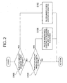
- Fig. 2 shows a subroutine flowchart showing a procedure of pilot injection control processing performed by such an electronic control unit 11.
- the pilot injection control processing in the embodiment of the invention is described with reference to the flowchart.
- the pilot injection control is designed to perform pilot multi-injection in a manner of properly using, depending on a predetermined condition, control where number of pilot injection is fixed to a predetermined value, and a kind of map control where a map being beforehand set and stored is used to determine number of pilot multi-injection from engine rotational frequency and fuel injection amount.
- a predetermined program as a main routine is executed for controlling fuel injection of the fuel injection valves 2-1 to 2-n in response to the subroutine processing shown in Fig. 2 , and fuel injection amount is known through executing the program. Therefore, the known fuel injection amount data can be used as the fuel injection amount in the step S100.
- the maximum value Qmax of the fuel injection amount Q is not a fixed value herein, and an optimum value thereof is successively calculated according to a predetermined computing equation depending on a predetermined condition such as engine rotational frequency or temperature of engine cooling water, that is, the maximum value is a dynamically determined value.
- step S100 In the case that the fuel injection amount Q exceeds the maximum value Qmax (in the case of YES) in the step S100, processing proceeds to step S102 described subsequently, and on the other hand, in the case that the fuel injection amount Q does not exceed the maximum value Qmax (in the case of NO) in the step S100, processing proceeds to step S104 described later.
- step S102 number-fixed control of pilot injection is started.
- a predetermined storage area of the electronic control unit 11 beforehand stores number of pilot multi-injection in the case that the fuel injection amount Q exceeds the maximum value Qmax, and in the step S102 or later, pilot multi-injection is performed with the stored number by the fuel injection valves 2-1 to 2-n.
- Such a correlation between fuel injection amount Q exceeding the maximum value Qmax and number of pilot multi-injection, the correlation being stored in the predetermined storage area of the electronic control unit 11, is stored in a form of a table in the predetermined storage area of the electronic control unit 11 in the embodiment of the invention.
- the minimum value Qmin of the fuel injection amount Q has a sense of so-called hysteresis to the maximum value Qmax, and a specific value thereof is preferably determined based on an experimental result, a simulation result and the like in the light of difference in stability of operation between individual vehicles or the like.
- step S104 when fuel injection amount Q is determined to be lower than the minimum value Qmin (in the case of YES), the number-fixed control of pilot multi-injection described in the step S102 is released (refer to step S106 in Fig. 2 ).
- number of pilot multi-injection is determined based on a map stored in a predetermined storage area of the electronic control unit 11.
- Fig. 3 shows an example of a map for determining pilot number in the embodiment of the invention, which is described below.
- pilot injection number is obtained from engine rotational frequency and fuel injection amount, and each numerical value in the map shows the pilot injection number.
- the respective numerical values in the map are merely shown as an example, and specifically appropriate values should be individually set based on a result of an experiment or simulation from a viewpoint of preventing misfire or the like while considering the scale of the diesel engine 1 or body size of a vehicle.
- a curve shown by a solid line shows an example of change in the maximum value Qmax
- a curve shown by a dotted line shows an example of change in the minimum value Qmin.
- the step S102 is performed on the assumption that fuel injection amount Q exceeds the maximum value Qmax. That is, in the example shown in Fig. 3 , the step is performed on the assumption that fuel injection amount Q is above the curve of the solid line showing the maximum value Qmax of the fuel injection amount Q.
- number of pilot injection is fixed to "1".
- a numerical value of "1" marked with a symbol A shows number of pilot injection in number-fixed control performed through execution of the step S102.
- the number is determined as follows. For example, in Fig. 3 , when engine rotational frequency is Na, and fuel injection amount is Qa at a particular point, "2" is selected as number of pilot injection, and pilot injection is performed with the selected number. However, if the engine rotational frequency is changed to Nb during that, "1" is newly selected as number of pilot injection, and thus number of pilot injection is changed. However, in the case that engine rotational frequency is transiently increased due to temporal depression of an accelerator (not shown) or the like, change in number of pilot injection may be undesirable, which has not been able to be avoided in the prior method.
- the pilot injection number is fixed to a predetermined pilot injection number. Therefore, unprepared change in pilot injection number may be avoided, resulting in stable pilot injection.
- step S106 When the step S106 is performed, that is, in a condition that fuel injection amount Q is below the curve shown by the dotted line in the example shown in Fig. 3 , in other words, in a condition that the fuel injection amount Q is lower than the minimum value Qmin, pilot injection is performed with number being determined according to the map shown in Fig. 3 based on engine rotational frequency and fuel injection amount in each case.
- the subroutine processing is repeatedly performed with a predetermined period determined by a not-shown main routine, and in the case that fuel injection amount Q is more than the maximum value Qmax in subroutine processing performed most recently, and fuel injection amount Q is lower than the maximum value Qmax, and more than the minimum value Qmin in subsequent subroutine processing, and therefore determination is made as NO in the step S104, number-fixed control (refer to step S102 in Fig. 2 ) is kept.
- a state where the pilot-number-fixed control is released in other words, a state where pilot number is controlled based on the map is kept.
- pilot number is controlled based on the map.
- setting of pilot injection number may be made at a desired point (singular point) while considering a particular condition such as misfire, and consequently smooth injection control can be achieved at a singular point at which number-fixed control may not meet such injection control.
- pilot injection control in the common-rail fuel injection control system was described.
- a configuration of the fuel injection control system need not be limited to the common rail type, and the invention may be similarly applied to a fuel injection control system having a different configuration.
- the fuel injection control system according to the invention, unprepared change in pilot injection number may be avoided, and consequently stable fuel injection control may be secured. Therefore, the system is particularly suitable for a fuel injection control system having a pilot injection function.
Landscapes
- Engineering & Computer Science (AREA)
- Chemical & Material Sciences (AREA)
- Combustion & Propulsion (AREA)
- Mechanical Engineering (AREA)
- General Engineering & Computer Science (AREA)
- Electrical Control Of Air Or Fuel Supplied To Internal-Combustion Engine (AREA)
- Fuel-Injection Apparatus (AREA)
- Combined Controls Of Internal Combustion Engines (AREA)
Abstract
Description
- The present invention relates to pilot injection control of a diesel internal-combustion engine, and particularly relates to pilot injection control that may achieve suppression in torque variation in a transient response of engine rotational frequency.
- In a diesel internal-combustion engine, pilot injection is performed with multi injection in order to achieve mild combustion and thus reduce engine vibration during combustion, which has been a well-known technique in the past. Furthermore, such pilot multi-injection is effective for preventing misfire at low temperature, or improving fuel consumption. Therefore, the pilot multi-injection is currently widely used (for example refer to patent document 1).
- Typically, the pilot multi-injection control includes a method where a plurality of maps are prepared depending on external environment such as ambient temperature so that number of pilot injection is determined using fuel injection amount and engine rotational frequency as parameters, and one of the maps is selected depending on external environment during pilot injection, and number of pilot multi-injection is determined from fuel injection amount and engine rotational frequency at that time.
- However, such so-called map control has a drawback that if number of pilot injection is changed in a transient response of engine rotational frequency, which may occur in the case of sudden depression of an accelerator, vibration in engine or variation in torque is induced. While such a drawback has been known in the past, most of pilot multi-injection control techniques are largely focused on reducing engine vibration during combustion, or on preventing misfire in an engine at low temperature. Therefore, a pilot multi-injection control technique giving full consideration to the above drawback is desired.
- Patent document 1: Japanese Patent Application Laid-open No.
2002-269229 - The invention was made in the light of the above circumstances, and provides a method of pilot injection control and a system thereof, which contributes to avoid change in number of pilot injection in a transient response of an engine, and thus enables improvement in driving feeling and travelling feeling.
- According to a first embodiment of the invention, a pilot injection control method is provided, which controls pilot injection performed before main injection of fuel by fuel injection valves, the method being configured such that
when fuel injection amount exceeds a predetermined maximum value, pilot multi-injection is performed with number being beforehand determined, and on the other hand, when fuel injection amount is lower than a predetermined minimum value, pilot multi-injection is performed with number being obtained by using a predetermined map for determining the number of pilot injection from engine rotational frequency and fuel injection amount. - According to a second embodiment of the invention, a fuel injection control system is provided, which has a plurality of fuel injection valves, and an electronic control unit for controlling operation of the fuel injection valves, and is configured to allow the fuel injection valves to perform main injection and pilot injection of fuel,
wherein the electronic control unit is configured to be externally inputted with engine rotational frequency and temperature of engine cooling water, and
the electronic control unit is configured to operate so that
when pilot injection is performed by the fuel injection valves, whether fuel injection amount immediately before the pilot injection is more than a predetermined maximum value is determined, and in the case that the fuel injection amount is determined to be more than the predetermined maximum value, pilot multi-injection is performed with number being beforehand determined, and on the other hand, in the case that the fuel injection amount is determined to be not more than the predetermined maximum value, whether fuel injection amount is lower than a predetermined minimum value is determined, and in the case that the fuel injection amount is determined to be lower than the predetermined minimum value, number of pilot injection is determined by using a predetermined map, being beforehand stored, for determining the number of pilot injection from engine rotational frequency and fuel injection amount, and pilot multi-injection is performed with the determined number. - According to the invention, in the case that engine rotational frequency is transiently changed, change in number of pilot injection can be avoided in an area where change in number of pilot injection tends to occur, which may suppress vibration in engine or variation in torque due to unprepared change in number of pilot injection, and consequently driving feeling may be advantageously improved.
-
-
FIG. 1 is a block diagram showing a configuration example of a fuel injection control system of the embodiment of the invention. -
FIG. 2 is a subroutine flowchart showing a procedure of pilot injection control processing performed by an electronic control unit of the fuel injection control system shown inFig. 1 . -
FIG. 3 is an explanatory diagram illustrating an example of a map for determining the number of pilot injection from engine rotational frequency and fuel injection amount. -
- 1
- diesel engine
- 2-1 to 2-n
- fuel injection valve
- 3
- common rail
- 4
- high-pressure pump
- 5
- feed pump
- 6
- fuel tank
- 11
- electronic control unit
- Hereinafter, a preferred embodiment of the invention will be described with reference to
Figs. 1 to 3 . - While particular members, layouts and the like are described below, they are not intended to limit the invention, and may be variously modified within a scope of the gist of the invention.
- First, a configuration example of a fuel injection control system using a pilot injection control method of the embodiment of the invention is described with reference to
Fig. 1 . - As the fuel injection control system of the embodiment of the invention, a common-rail fuel injection control system is particularly configured.
- The common-rail fuel injection control system is configured in a manner of being roughly divided into a plurality of fuel injection valves 2-1 to 2-n that inject fuel and supply the fuel to cylinders of a
diesel engine 1 respectively; acommon rail 3 that stores high-pressure fuel to be supplied to the fuel injection valves 2-1 to 2-n; a high-pressure pump 4 that feeds the high-pressure fuel under pressure to thecommon rail 3; afeed pump 5 that supplies fuel from afuel tank 6 to the high-pressure pump 4; and anelectronic control unit 11 that performs pilot injection control described later. Such a configuration itself is the same as a basic configuration of this type of fuel injection control system being well known in the past. - In such a configuration, fuel in the
fuel tank 6 is drawn up into the high-pressure pump 4 by afeed pump 5, and the drawn-up fuel is fed under pressure as high-pressure fuel to thecommon rail 3 by the high-pressure pump 4. While being omitted to be shown, piping is provided to return surplus fuel in thecommon rail 3 to thefuel tank 6. - The fuel injection valves 2-1 to 2-n are provided for respective cylinders of the
diesel engine 1, which are supplied with high-pressure fuel from thecommon rail 3, and perform pilot injection or main injection according to control by theelectronic control unit 11 respectively. - The
electronic control unit 11 is configured to have main components such as a microcomputer (not shown) having a well-known configuration as a core component, storage elements (not shown) such as RAM and ROM, and a drive circuit (not shown) for driving the fuel injection valves 2-1 to 2-n. - Such an
electronic control unit 11 is inputted with detection signals to be used for engine operation control or injection control from various sensors such as a rotation sensor 12 for detecting engine rotational frequency, anaccelerator opening sensor 13 for detecting a degree of accelerator opening, anambient temperature sensor 14 for detecting ambient temperature, and awater temperature sensor 15 for detecting temperature of cooling water of thediesel engine 1. -
Fig. 2 shows a subroutine flowchart showing a procedure of pilot injection control processing performed by such anelectronic control unit 11. Hereinafter, the pilot injection control processing in the embodiment of the invention is described with reference to the flowchart. - First, to describe summary of the pilot injection control processing in the embodiment of the invention, the pilot injection control is designed to perform pilot multi-injection in a manner of properly using, depending on a predetermined condition, control where number of pilot injection is fixed to a predetermined value, and a kind of map control where a map being beforehand set and stored is used to determine number of pilot multi-injection from engine rotational frequency and fuel injection amount.
- Hereinafter, the pilot injection control processing is specifically described with reference to
Fig. 2 . - First, when the
electronic control unit 11 starts processing to perform pilot injection, whether fuel injection amount Q immediately before the pilot injection exceeds a predetermined maximum value Qmax is determined (refer to step S100 inFig. 2 ). InFig. 2 , such processing is mentioned as "INJECTION AMOUNT MAXIMUM CHECK" for convenience. - In the
electronic control unit 11, a predetermined program as a main routine is executed for controlling fuel injection of the fuel injection valves 2-1 to 2-n in response to the subroutine processing shown inFig. 2 , and fuel injection amount is known through executing the program. Therefore, the known fuel injection amount data can be used as the fuel injection amount in the step S100. - The maximum value Qmax of the fuel injection amount Q is not a fixed value herein, and an optimum value thereof is successively calculated according to a predetermined computing equation depending on a predetermined condition such as engine rotational frequency or temperature of engine cooling water, that is, the maximum value is a dynamically determined value.
- In the case that the fuel injection amount Q exceeds the maximum value Qmax (in the case of YES) in the step S100, processing proceeds to step S102 described subsequently, and on the other hand, in the case that the fuel injection amount Q does not exceed the maximum value Qmax (in the case of NO) in the step S100, processing proceeds to step S104 described later.
- In the step S102, number-fixed control of pilot injection is started. A predetermined storage area of the
electronic control unit 11 beforehand stores number of pilot multi-injection in the case that the fuel injection amount Q exceeds the maximum value Qmax, and in the step S102 or later, pilot multi-injection is performed with the stored number by the fuel injection valves 2-1 to 2-n. - Such a correlation between fuel injection amount Q exceeding the maximum value Qmax and number of pilot multi-injection, the correlation being stored in the predetermined storage area of the
electronic control unit 11, is stored in a form of a table in the predetermined storage area of theelectronic control unit 11 in the embodiment of the invention. - On the other hand, in the step S104, whether fuel injection amount Q is lower than a minimum value Qmin is determined. From the viewpoint of securing stability of operation, the minimum value Qmin of the fuel injection amount Q has a sense of so-called hysteresis to the maximum value Qmax, and a specific value thereof is preferably determined based on an experimental result, a simulation result and the like in the light of difference in stability of operation between individual vehicles or the like.
- In the step S104, when fuel injection amount Q is determined to be lower than the minimum value Qmin (in the case of YES), the number-fixed control of pilot multi-injection described in the step S102 is released (refer to step S106 in
Fig. 2 ). - Thus, after that, number of pilot multi-injection is determined based on a map stored in a predetermined storage area of the
electronic control unit 11. -
Fig. 3 shows an example of a map for determining pilot number in the embodiment of the invention, which is described below. - In the map shown in
Fig. 3 , pilot injection number is obtained from engine rotational frequency and fuel injection amount, and each numerical value in the map shows the pilot injection number. The respective numerical values in the map are merely shown as an example, and specifically appropriate values should be individually set based on a result of an experiment or simulation from a viewpoint of preventing misfire or the like while considering the scale of thediesel engine 1 or body size of a vehicle. - In
Fig. 3 , a curve shown by a solid line shows an example of change in the maximum value Qmax, and a curve shown by a dotted line shows an example of change in the minimum value Qmin. - To newly describe the step S102 with reference to the figure, the step S102 is performed on the assumption that fuel injection amount Q exceeds the maximum value Qmax. That is, in the example shown in
Fig. 3 , the step is performed on the assumption that fuel injection amount Q is above the curve of the solid line showing the maximum value Qmax of the fuel injection amount Q. - In this case, number of pilot injection is fixed to "1". In
Fig. 3 , a numerical value of "1" marked with a symbol A shows number of pilot injection in number-fixed control performed through execution of the step S102. - Therefore, in the prior method where number of pilot injection is determined only by a map, the number is determined as follows. For example, in
Fig. 3 , when engine rotational frequency is Na, and fuel injection amount is Qa at a particular point, "2" is selected as number of pilot injection, and pilot injection is performed with the selected number. However, if the engine rotational frequency is changed to Nb during that, "1" is newly selected as number of pilot injection, and thus number of pilot injection is changed. However, in the case that engine rotational frequency is transiently increased due to temporal depression of an accelerator (not shown) or the like, change in number of pilot injection may be undesirable, which has not been able to be avoided in the prior method. - For example, in the map shown in
Fig. 3 , in the case that engine rotational frequency is transiently changed near a boundary between pilot number "2" and pilot number "1", and along with this, number of pilot injection is changed according to the map ofFig. 3 , vibration in thediesel engine 1 or variation in torque temporally occurs, which has sometimes caused a driver to feel reduction in driving feeling or travelling feeling. - On the other hand, in the embodiment of the invention, in the case that fuel injection amount Q exceeds the maximum value Qmax at a boundary portion of pilot injection number in a map, at which the pilot injection number may be changed as in the example, the pilot injection number is fixed to a predetermined pilot injection number. Therefore, unprepared change in pilot injection number may be avoided, resulting in stable pilot injection.
- When the step S106 is performed, that is, in a condition that fuel injection amount Q is below the curve shown by the dotted line in the example shown in
Fig. 3 , in other words, in a condition that the fuel injection amount Q is lower than the minimum value Qmin, pilot injection is performed with number being determined according to the map shown inFig. 3 based on engine rotational frequency and fuel injection amount in each case. - To return to description of
Fig. 2 , in the case that fuel injection amount Q is determined to be not lower than the minimum value Qmin (in the case of NO), in other words, in the case that fuel injection amount Q is more than the minimum value Qmin, and lower than the maximum value Qmax, a state is kept, in which pilot injection is performed with number being most recently selected. - That is, the subroutine processing is repeatedly performed with a predetermined period determined by a not-shown main routine, and in the case that fuel injection amount Q is more than the maximum value Qmax in subroutine processing performed most recently, and fuel injection amount Q is lower than the maximum value Qmax, and more than the minimum value Qmin in subsequent subroutine processing, and therefore determination is made as NO in the step S104, number-fixed control (refer to step S102 in
Fig. 2 ) is kept. - On the other hand, for example, in a condition that fuel injection amount Q is lower than the minimum value Qmin, and the pilot-number-fixed control is released (refer to step S106 in
Fig. 2 ) in subroutine processing performed most recently, when the fuel injection amount Q is determined to be not lower than the minimum value Qmin in subsequent subroutine processing (refer to step S104 inFig. 2 ), a state where the pilot-number-fixed control is released, in other words, a state where pilot number is controlled based on the map is kept. - In this way, in the case that fuel injection amount is equal to or less than the predetermined amount, pilot number is controlled based on the map. Thus, setting of pilot injection number may be made at a desired point (singular point) while considering a particular condition such as misfire, and consequently smooth injection control can be achieved at a singular point at which number-fixed control may not meet such injection control.
- In the configuration example, pilot injection control in the common-rail fuel injection control system was described. However, a configuration of the fuel injection control system need not be limited to the common rail type, and the invention may be similarly applied to a fuel injection control system having a different configuration.
- As described hereinbefore, according to the fuel injection control system according to the invention, unprepared change in pilot injection number may be avoided, and consequently stable fuel injection control may be secured. Therefore, the system is particularly suitable for a fuel injection control system having a pilot injection function.
Claims (4)
- A pilot injection control method controlling pilot injection performed before main injection of fuel by fuel injection valves,
characterized in that:when fuel injection amount exceeds a predetermined maximum value, pilot multi-injection is performed with number being beforehand determined, and on the other hand, when fuel injection amount is lower than a predetermined minimum value, pilot multi-injection is performed with number being obtained by using a predetermined map for determining the number of pilot injection from engine rotational frequency and fuel injection amount. - The pilot injection control method according to claim 1,
characterized in that:the predetermined maximum value is successively set based on at least engine rotational frequency and temperature of engine cooling water. - A fuel injection control system, which has a plurality of fuel injection valves, and an electronic control unit for controlling operation of the fuel injection valves, and is configured to allow the fuel injection valves to perform main injection and pilot injection of fuel, characterized in that:the electronic control unit is configured to be externally inputted with engine rotational frequency and temperature of engine cooling water, andthe electronic control unit is configured to operate so thatwhen pilot injection is performed by the fuel injection valves, whether fuel injection amount immediately before the pilot injection is more than a predetermined maximum value is determined, and in the case that the fuel injection amount is determined to be more than the predetermined maximum value, pilot multi-injection is performed with number being beforehand determined, and on the other hand, in the case that the fuel injection amount is determined to be not more than the predetermined maximum value, whether fuel injection amount is lower than a predetermined minimum value is determined, and in the case that the fuel injection amount is determined to be lower than the predetermined minimum value, number of pilot injection is determined by using a predetermined map, being beforehand stored, for determining the number of pilot injection from engine rotational frequency and fuel injection amount, and pilot multi-injection is performed with the determined number.
- The fuel injection control system according to claim 3,
characterized in that:the electronic control unit is configured to successively set the predetermined maximum value based on at least engine rotational frequency and temperature of engine cooling water.
Applications Claiming Priority (2)
| Application Number | Priority Date | Filing Date | Title |
|---|---|---|---|
| JP2006306071A JP4538442B2 (en) | 2006-11-11 | 2006-11-11 | Pilot injection control method and apparatus |
| PCT/JP2007/071529 WO2008059730A1 (en) | 2006-11-11 | 2007-11-06 | Pilot jet control method and device therefor |
Publications (3)
| Publication Number | Publication Date |
|---|---|
| EP2083160A1 true EP2083160A1 (en) | 2009-07-29 |
| EP2083160A4 EP2083160A4 (en) | 2011-10-05 |
| EP2083160B1 EP2083160B1 (en) | 2012-10-10 |
Family
ID=39401539
Family Applications (1)
| Application Number | Title | Priority Date | Filing Date |
|---|---|---|---|
| EP07831261A Not-in-force EP2083160B1 (en) | 2006-11-11 | 2007-11-06 | Pilot jet control method and device therefor |
Country Status (6)
| Country | Link |
|---|---|
| US (1) | US8448625B2 (en) |
| EP (1) | EP2083160B1 (en) |
| JP (1) | JP4538442B2 (en) |
| KR (1) | KR20090079925A (en) |
| CN (1) | CN101535621B (en) |
| WO (1) | WO2008059730A1 (en) |
Cited By (1)
| Publication number | Priority date | Publication date | Assignee | Title |
|---|---|---|---|---|
| FR2964701A1 (en) * | 2010-09-14 | 2012-03-16 | Hyundai Motor Co Ltd | SYSTEM AND METHOD FOR CONTROLLING THE NUMBER OF PILOT INJECTIONS |
Families Citing this family (6)
| Publication number | Priority date | Publication date | Assignee | Title |
|---|---|---|---|---|
| JP4816651B2 (en) * | 2008-01-25 | 2011-11-16 | トヨタ自動車株式会社 | Fuel injection control device for internal combustion engine |
| JP5809796B2 (en) * | 2010-11-30 | 2015-11-11 | 日立オートモティブシステムズ株式会社 | Fuel injection control device for internal combustion engine |
| CN103291481B (en) * | 2013-05-24 | 2016-02-17 | 潍柴动力股份有限公司 | A kind of pre-spray controlling method of motor, device and electrical control system for engine |
| US20150285178A1 (en) * | 2014-04-02 | 2015-10-08 | Caterpillar Inc. | Reactivity controlled compression ignition engine and method of combustion phasing control |
| DE102016110112B9 (en) * | 2015-06-11 | 2021-04-01 | Denso Corporation | Fuel injector |
| JP7322819B2 (en) * | 2020-06-09 | 2023-08-08 | トヨタ自動車株式会社 | Control device for internal combustion engine |
Family Cites Families (19)
| Publication number | Priority date | Publication date | Assignee | Title |
|---|---|---|---|---|
| JP3915329B2 (en) * | 1999-07-21 | 2007-05-16 | 日産自動車株式会社 | Fuel injection control device for diesel engine |
| DE10056477B9 (en) * | 1999-11-17 | 2016-03-03 | Denso Corporation | Fuel injection device for an internal combustion engine |
| JP2002206447A (en) * | 2001-01-11 | 2002-07-26 | Hino Motors Ltd | Engine fuel injection method |
| JP2002269229A (en) | 2001-03-14 | 2002-09-20 | Denso Corp | Medical management system |
| JP2003106192A (en) * | 2001-09-27 | 2003-04-09 | Toyota Motor Corp | Fuel injection control device for internal combustion engine |
| JP3864754B2 (en) * | 2001-10-25 | 2007-01-10 | 日産自動車株式会社 | Control device for internal combustion engine |
| JP4122803B2 (en) * | 2002-03-12 | 2008-07-23 | トヨタ自動車株式会社 | Fuel injection control device for diesel engine |
| JP2003343331A (en) * | 2002-05-24 | 2003-12-03 | Denso Corp | Injection rate control device for internal combustion engine |
| JP3966096B2 (en) * | 2002-06-20 | 2007-08-29 | 株式会社デンソー | Injection amount control device for internal combustion engine |
| JP4161690B2 (en) * | 2002-11-20 | 2008-10-08 | 株式会社デンソー | Accumulated fuel injection system |
| JP4158577B2 (en) * | 2003-04-02 | 2008-10-01 | 日産自動車株式会社 | Engine combustion control device |
| JP4254361B2 (en) * | 2003-06-12 | 2009-04-15 | トヨタ自動車株式会社 | Fuel injection device for internal combustion engine |
| JP4277677B2 (en) * | 2003-06-27 | 2009-06-10 | 株式会社デンソー | Injection quantity control device for diesel engine |
| JP4174773B2 (en) * | 2004-04-26 | 2008-11-05 | トヨタ自動車株式会社 | Engine control apparatus and method |
| JP3931900B2 (en) * | 2004-10-06 | 2007-06-20 | いすゞ自動車株式会社 | Diesel engine control device |
| JP4289280B2 (en) * | 2004-11-01 | 2009-07-01 | 株式会社デンソー | Injection amount learning control device |
| JP2007187149A (en) * | 2005-12-13 | 2007-07-26 | Nissan Motor Co Ltd | Engine fuel injection control method and fuel injection control device |
| DE102005059908A1 (en) * | 2005-12-15 | 2007-06-28 | Robert Bosch Gmbh | Method for metering fuel into combustion chambers of an internal combustion engine |
| JP4552899B2 (en) * | 2006-06-06 | 2010-09-29 | 株式会社デンソー | Fuel injection control device |
-
2006
- 2006-11-11 JP JP2006306071A patent/JP4538442B2/en not_active Expired - Fee Related
-
2007
- 2007-11-06 EP EP07831261A patent/EP2083160B1/en not_active Not-in-force
- 2007-11-06 WO PCT/JP2007/071529 patent/WO2008059730A1/en not_active Ceased
- 2007-11-06 KR KR1020097009507A patent/KR20090079925A/en not_active Ceased
- 2007-11-06 CN CN2007800416091A patent/CN101535621B/en not_active Expired - Fee Related
- 2007-11-06 US US12/514,403 patent/US8448625B2/en not_active Expired - Fee Related
Cited By (2)
| Publication number | Priority date | Publication date | Assignee | Title |
|---|---|---|---|---|
| FR2964701A1 (en) * | 2010-09-14 | 2012-03-16 | Hyundai Motor Co Ltd | SYSTEM AND METHOD FOR CONTROLLING THE NUMBER OF PILOT INJECTIONS |
| US9091225B2 (en) | 2010-09-14 | 2015-07-28 | Hyundai Motor Company | System and method for controlling the number of pilot injections |
Also Published As
| Publication number | Publication date |
|---|---|
| JP2008121546A (en) | 2008-05-29 |
| EP2083160B1 (en) | 2012-10-10 |
| US20100139614A1 (en) | 2010-06-10 |
| WO2008059730A1 (en) | 2008-05-22 |
| JP4538442B2 (en) | 2010-09-08 |
| EP2083160A4 (en) | 2011-10-05 |
| US8448625B2 (en) | 2013-05-28 |
| CN101535621A (en) | 2009-09-16 |
| KR20090079925A (en) | 2009-07-22 |
| CN101535621B (en) | 2012-06-13 |
Similar Documents
| Publication | Publication Date | Title |
|---|---|---|
| EP2083160A1 (en) | Pilot jet control method and device therefor | |
| US7503313B2 (en) | Method and device for controlling an internal combustion engine | |
| EP2085596A2 (en) | Fuel injector for internal combustion engine | |
| US8528522B2 (en) | Superimposed pressure control of the common rail system | |
| US20050115533A1 (en) | Fuel injection device | |
| US20120037122A1 (en) | Method and device for controlling a fuel metering system for an internal combustion engine | |
| EP2628924A1 (en) | Controller of construction machine | |
| US9567937B2 (en) | Method and device for operating a fuel injection device, especially of a motor vehicle | |
| US6748924B2 (en) | Method and system for controlling fuel injection | |
| US6298831B1 (en) | System for operating a fuel supply system for an internal combustion engine, in particular of a motor vehicle | |
| US20100100302A1 (en) | Method and Device For Dosing Fuel Which Is To Be Injected Into A Combustion Chamber Of An Internal Combustion Engine | |
| US20120004832A1 (en) | Method and device for operating a drive unit | |
| JP2007127080A (en) | Control device for accumulator fuel system | |
| EP2574761B1 (en) | A fuel injection control device for an internal combustion engine | |
| EP1983182A2 (en) | Engine fuel pump control apparatus | |
| JP5780669B2 (en) | Engine rotation control mode switching method and engine rotation control device | |
| EP1933021A2 (en) | Fuel injection control apparatus for diesel engine | |
| JP4532532B2 (en) | Fuel injection control device and fuel injection system | |
| JP4755608B2 (en) | Fuel injection control device | |
| JP2004360688A (en) | Compensation device for engine output loss | |
| JP4735621B2 (en) | Injection amount learning device | |
| WO2009020416A1 (en) | A turbine speed control method | |
| JP3827367B2 (en) | Fuel injection control method | |
| JP2013217213A (en) | Limp-home mode shift control method, and common rail fuel injection control device | |
| EP1876343A1 (en) | Fuel supply apparatus for internal combustion engine |
Legal Events
| Date | Code | Title | Description |
|---|---|---|---|
| PUAI | Public reference made under article 153(3) epc to a published international application that has entered the european phase |
Free format text: ORIGINAL CODE: 0009012 |
|
| 17P | Request for examination filed |
Effective date: 20090612 |
|
| AK | Designated contracting states |
Kind code of ref document: A1 Designated state(s): AT BE BG CH CY CZ DE DK EE ES FI FR GB GR HU IE IS IT LI LT LU LV MC MT NL PL PT RO SE SI SK TR |
|
| DAX | Request for extension of the european patent (deleted) | ||
| A4 | Supplementary search report drawn up and despatched |
Effective date: 20110901 |
|
| RIC1 | Information provided on ipc code assigned before grant |
Ipc: F02D 41/40 20060101ALI20110826BHEP Ipc: F02D 41/10 20060101ALI20110826BHEP Ipc: F02M 45/02 20060101ALI20110826BHEP Ipc: F02D 45/00 20060101ALI20110826BHEP Ipc: F02D 41/38 20060101AFI20110826BHEP |
|
| GRAP | Despatch of communication of intention to grant a patent |
Free format text: ORIGINAL CODE: EPIDOSNIGR1 |
|
| GRAS | Grant fee paid |
Free format text: ORIGINAL CODE: EPIDOSNIGR3 |
|
| GRAA | (expected) grant |
Free format text: ORIGINAL CODE: 0009210 |
|
| AK | Designated contracting states |
Kind code of ref document: B1 Designated state(s): AT BE BG CH CY CZ DE DK EE ES FI FR GB GR HU IE IS IT LI LT LU LV MC MT NL PL PT RO SE SI SK TR |
|
| REG | Reference to a national code |
Ref country code: GB Ref legal event code: FG4D |
|
| REG | Reference to a national code |
Ref country code: AT Ref legal event code: REF Ref document number: 579090 Country of ref document: AT Kind code of ref document: T Effective date: 20121015 Ref country code: CH Ref legal event code: EP |
|
| REG | Reference to a national code |
Ref country code: IE Ref legal event code: FG4D |
|
| REG | Reference to a national code |
Ref country code: DE Ref legal event code: R096 Ref document number: 602007026049 Country of ref document: DE Effective date: 20121206 |
|
| PG25 | Lapsed in a contracting state [announced via postgrant information from national office to epo] |
Ref country code: SI Free format text: LAPSE BECAUSE OF FAILURE TO SUBMIT A TRANSLATION OF THE DESCRIPTION OR TO PAY THE FEE WITHIN THE PRESCRIBED TIME-LIMIT Effective date: 20121010 |
|
| REG | Reference to a national code |
Ref country code: NL Ref legal event code: VDEP Effective date: 20121010 |
|
| REG | Reference to a national code |
Ref country code: AT Ref legal event code: MK05 Ref document number: 579090 Country of ref document: AT Kind code of ref document: T Effective date: 20121010 |
|
| REG | Reference to a national code |
Ref country code: LT Ref legal event code: MG4D |
|
| PG25 | Lapsed in a contracting state [announced via postgrant information from national office to epo] |
Ref country code: LT Free format text: LAPSE BECAUSE OF FAILURE TO SUBMIT A TRANSLATION OF THE DESCRIPTION OR TO PAY THE FEE WITHIN THE PRESCRIBED TIME-LIMIT Effective date: 20121010 Ref country code: NL Free format text: LAPSE BECAUSE OF FAILURE TO SUBMIT A TRANSLATION OF THE DESCRIPTION OR TO PAY THE FEE WITHIN THE PRESCRIBED TIME-LIMIT Effective date: 20121010 Ref country code: SE Free format text: LAPSE BECAUSE OF FAILURE TO SUBMIT A TRANSLATION OF THE DESCRIPTION OR TO PAY THE FEE WITHIN THE PRESCRIBED TIME-LIMIT Effective date: 20121010 Ref country code: FI Free format text: LAPSE BECAUSE OF FAILURE TO SUBMIT A TRANSLATION OF THE DESCRIPTION OR TO PAY THE FEE WITHIN THE PRESCRIBED TIME-LIMIT Effective date: 20121010 Ref country code: IS Free format text: LAPSE BECAUSE OF FAILURE TO SUBMIT A TRANSLATION OF THE DESCRIPTION OR TO PAY THE FEE WITHIN THE PRESCRIBED TIME-LIMIT Effective date: 20130210 Ref country code: ES Free format text: LAPSE BECAUSE OF FAILURE TO SUBMIT A TRANSLATION OF THE DESCRIPTION OR TO PAY THE FEE WITHIN THE PRESCRIBED TIME-LIMIT Effective date: 20130121 |
|
| PG25 | Lapsed in a contracting state [announced via postgrant information from national office to epo] |
Ref country code: CY Free format text: LAPSE BECAUSE OF FAILURE TO SUBMIT A TRANSLATION OF THE DESCRIPTION OR TO PAY THE FEE WITHIN THE PRESCRIBED TIME-LIMIT Effective date: 20121010 Ref country code: BE Free format text: LAPSE BECAUSE OF FAILURE TO SUBMIT A TRANSLATION OF THE DESCRIPTION OR TO PAY THE FEE WITHIN THE PRESCRIBED TIME-LIMIT Effective date: 20121010 Ref country code: PL Free format text: LAPSE BECAUSE OF FAILURE TO SUBMIT A TRANSLATION OF THE DESCRIPTION OR TO PAY THE FEE WITHIN THE PRESCRIBED TIME-LIMIT Effective date: 20121010 Ref country code: GR Free format text: LAPSE BECAUSE OF FAILURE TO SUBMIT A TRANSLATION OF THE DESCRIPTION OR TO PAY THE FEE WITHIN THE PRESCRIBED TIME-LIMIT Effective date: 20130111 Ref country code: PT Free format text: LAPSE BECAUSE OF FAILURE TO SUBMIT A TRANSLATION OF THE DESCRIPTION OR TO PAY THE FEE WITHIN THE PRESCRIBED TIME-LIMIT Effective date: 20130211 Ref country code: LV Free format text: LAPSE BECAUSE OF FAILURE TO SUBMIT A TRANSLATION OF THE DESCRIPTION OR TO PAY THE FEE WITHIN THE PRESCRIBED TIME-LIMIT Effective date: 20121010 |
|
| PG25 | Lapsed in a contracting state [announced via postgrant information from national office to epo] |
Ref country code: AT Free format text: LAPSE BECAUSE OF FAILURE TO SUBMIT A TRANSLATION OF THE DESCRIPTION OR TO PAY THE FEE WITHIN THE PRESCRIBED TIME-LIMIT Effective date: 20121010 |
|
| REG | Reference to a national code |
Ref country code: CH Ref legal event code: PL |
|
| PG25 | Lapsed in a contracting state [announced via postgrant information from national office to epo] |
Ref country code: CZ Free format text: LAPSE BECAUSE OF FAILURE TO SUBMIT A TRANSLATION OF THE DESCRIPTION OR TO PAY THE FEE WITHIN THE PRESCRIBED TIME-LIMIT Effective date: 20121010 Ref country code: DK Free format text: LAPSE BECAUSE OF FAILURE TO SUBMIT A TRANSLATION OF THE DESCRIPTION OR TO PAY THE FEE WITHIN THE PRESCRIBED TIME-LIMIT Effective date: 20121010 Ref country code: LI Free format text: LAPSE BECAUSE OF NON-PAYMENT OF DUE FEES Effective date: 20121130 Ref country code: EE Free format text: LAPSE BECAUSE OF FAILURE TO SUBMIT A TRANSLATION OF THE DESCRIPTION OR TO PAY THE FEE WITHIN THE PRESCRIBED TIME-LIMIT Effective date: 20121010 Ref country code: BG Free format text: LAPSE BECAUSE OF FAILURE TO SUBMIT A TRANSLATION OF THE DESCRIPTION OR TO PAY THE FEE WITHIN THE PRESCRIBED TIME-LIMIT Effective date: 20130110 Ref country code: CH Free format text: LAPSE BECAUSE OF NON-PAYMENT OF DUE FEES Effective date: 20121130 Ref country code: SK Free format text: LAPSE BECAUSE OF FAILURE TO SUBMIT A TRANSLATION OF THE DESCRIPTION OR TO PAY THE FEE WITHIN THE PRESCRIBED TIME-LIMIT Effective date: 20121010 |
|
| REG | Reference to a national code |
Ref country code: IE Ref legal event code: MM4A |
|
| PLBE | No opposition filed within time limit |
Free format text: ORIGINAL CODE: 0009261 |
|
| STAA | Information on the status of an ep patent application or granted ep patent |
Free format text: STATUS: NO OPPOSITION FILED WITHIN TIME LIMIT |
|
| PG25 | Lapsed in a contracting state [announced via postgrant information from national office to epo] |
Ref country code: IT Free format text: LAPSE BECAUSE OF FAILURE TO SUBMIT A TRANSLATION OF THE DESCRIPTION OR TO PAY THE FEE WITHIN THE PRESCRIBED TIME-LIMIT Effective date: 20121010 Ref country code: RO Free format text: LAPSE BECAUSE OF FAILURE TO SUBMIT A TRANSLATION OF THE DESCRIPTION OR TO PAY THE FEE WITHIN THE PRESCRIBED TIME-LIMIT Effective date: 20121010 |
|
| 26N | No opposition filed |
Effective date: 20130711 |
|
| PG25 | Lapsed in a contracting state [announced via postgrant information from national office to epo] |
Ref country code: IE Free format text: LAPSE BECAUSE OF NON-PAYMENT OF DUE FEES Effective date: 20121106 |
|
| REG | Reference to a national code |
Ref country code: DE Ref legal event code: R097 Ref document number: 602007026049 Country of ref document: DE Effective date: 20130711 |
|
| PG25 | Lapsed in a contracting state [announced via postgrant information from national office to epo] |
Ref country code: MT Free format text: LAPSE BECAUSE OF FAILURE TO SUBMIT A TRANSLATION OF THE DESCRIPTION OR TO PAY THE FEE WITHIN THE PRESCRIBED TIME-LIMIT Effective date: 20121010 |
|
| PG25 | Lapsed in a contracting state [announced via postgrant information from national office to epo] |
Ref country code: MC Free format text: LAPSE BECAUSE OF NON-PAYMENT OF DUE FEES Effective date: 20121130 Ref country code: TR Free format text: LAPSE BECAUSE OF FAILURE TO SUBMIT A TRANSLATION OF THE DESCRIPTION OR TO PAY THE FEE WITHIN THE PRESCRIBED TIME-LIMIT Effective date: 20121010 |
|
| PG25 | Lapsed in a contracting state [announced via postgrant information from national office to epo] |
Ref country code: LU Free format text: LAPSE BECAUSE OF NON-PAYMENT OF DUE FEES Effective date: 20121106 |
|
| PG25 | Lapsed in a contracting state [announced via postgrant information from national office to epo] |
Ref country code: HU Free format text: LAPSE BECAUSE OF FAILURE TO SUBMIT A TRANSLATION OF THE DESCRIPTION OR TO PAY THE FEE WITHIN THE PRESCRIBED TIME-LIMIT Effective date: 20071106 |
|
| REG | Reference to a national code |
Ref country code: FR Ref legal event code: PLFP Year of fee payment: 9 |
|
| REG | Reference to a national code |
Ref country code: FR Ref legal event code: PLFP Year of fee payment: 10 |
|
| REG | Reference to a national code |
Ref country code: FR Ref legal event code: PLFP Year of fee payment: 11 |
|
| PGFP | Annual fee paid to national office [announced via postgrant information from national office to epo] |
Ref country code: FR Payment date: 20191121 Year of fee payment: 13 |
|
| PGFP | Annual fee paid to national office [announced via postgrant information from national office to epo] |
Ref country code: GB Payment date: 20191126 Year of fee payment: 13 Ref country code: DE Payment date: 20200124 Year of fee payment: 13 |
|
| REG | Reference to a national code |
Ref country code: DE Ref legal event code: R119 Ref document number: 602007026049 Country of ref document: DE |
|
| GBPC | Gb: european patent ceased through non-payment of renewal fee |
Effective date: 20201106 |
|
| PG25 | Lapsed in a contracting state [announced via postgrant information from national office to epo] |
Ref country code: FR Free format text: LAPSE BECAUSE OF NON-PAYMENT OF DUE FEES Effective date: 20201130 |
|
| PG25 | Lapsed in a contracting state [announced via postgrant information from national office to epo] |
Ref country code: GB Free format text: LAPSE BECAUSE OF NON-PAYMENT OF DUE FEES Effective date: 20201106 Ref country code: DE Free format text: LAPSE BECAUSE OF NON-PAYMENT OF DUE FEES Effective date: 20210601 |