EP2083141A2 - Concealed hinge - Google Patents
Concealed hinge Download PDFInfo
- Publication number
- EP2083141A2 EP2083141A2 EP20090151441 EP09151441A EP2083141A2 EP 2083141 A2 EP2083141 A2 EP 2083141A2 EP 20090151441 EP20090151441 EP 20090151441 EP 09151441 A EP09151441 A EP 09151441A EP 2083141 A2 EP2083141 A2 EP 2083141A2
- Authority
- EP
- European Patent Office
- Prior art keywords
- hinge
- levers
- pair
- lever
- wings
- Prior art date
- Legal status (The legal status is an assumption and is not a legal conclusion. Google has not performed a legal analysis and makes no representation as to the accuracy of the status listed.)
- Withdrawn
Links
- 238000004519 manufacturing process Methods 0.000 claims description 3
- 238000000034 method Methods 0.000 claims 1
- XEEYBQQBJWHFJM-UHFFFAOYSA-N Iron Chemical compound [Fe] XEEYBQQBJWHFJM-UHFFFAOYSA-N 0.000 description 8
- 229910052742 iron Inorganic materials 0.000 description 4
- 239000000463 material Substances 0.000 description 4
- 229910000831 Steel Inorganic materials 0.000 description 3
- 239000010959 steel Substances 0.000 description 3
- 238000010276 construction Methods 0.000 description 2
- 238000003780 insertion Methods 0.000 description 2
- 230000037431 insertion Effects 0.000 description 2
- 239000004411 aluminium Substances 0.000 description 1
- XAGFODPZIPBFFR-UHFFFAOYSA-N aluminium Chemical compound [Al] XAGFODPZIPBFFR-UHFFFAOYSA-N 0.000 description 1
- 229910052782 aluminium Inorganic materials 0.000 description 1
- 238000012986 modification Methods 0.000 description 1
- 230000004048 modification Effects 0.000 description 1
- 238000011017 operating method Methods 0.000 description 1
- 230000000717 retained effect Effects 0.000 description 1
- 238000005476 soldering Methods 0.000 description 1
- 239000007787 solid Substances 0.000 description 1
- 229910001220 stainless steel Inorganic materials 0.000 description 1
- 239000010935 stainless steel Substances 0.000 description 1
Images


Classifications
-
- E—FIXED CONSTRUCTIONS
- E05—LOCKS; KEYS; WINDOW OR DOOR FITTINGS; SAFES
- E05D—HINGES OR SUSPENSION DEVICES FOR DOORS, WINDOWS OR WINGS
- E05D3/00—Hinges with pins
- E05D3/06—Hinges with pins with two or more pins
- E05D3/18—Hinges with pins with two or more pins with sliding pins or guides
- E05D3/186—Scissors hinges, with two crossing levers and five parallel pins
Definitions
- the present invention relates to a concealed hinge.
- a concealed hinge is a hinge that is completely embedded into the structure of the piece of furniture or the door/window on which it is mounted and therefore, contrary to the conventional "visible" hinges, it cannot be seen from the outside and the inside of the structure on which it is mounted.
- the invention concerns a concealed hinge for iron or aluminium tubular members of the kind employed for making windows, doors and similar components.
- Concealed hinges are employed when it is desired to avoid any additional bulk and when, for aesthetical reasons, it is preferred that the hinge cannot be seen with respect to the remaining parts of the structure on which it is mounted.
- Such hinges are formed of two parts or wings, one of which is fastened to the door/window casing and the other is fastened to the door/window frame, so as to enable rotation of one wing relative to the other.
- Patent publication EP 1538290 A in the name of the Applicant discloses a concealed hinge configured to limit the relative rotation of the wings to a predetermined angle.
- the prior art hinge includes a curved guide in which a member connecting the wings slides. Thanks to such a configuration, the curved guide of the hinge, by limiting the sliding of the connecting member, is arranged to limit the rotation angle of the wings.
- the present invention also concerns a concealed hinge assembly, as well as a method of manufacturing a concealed hinge.
- the hinge includes a plurality of levers pivotally mounted so that they define a first and a second lever set, and a pair of wings each having a pair of slots and a pair of holes in which the first and second lever sets are alternately pivotally mounted.
- the hinge slots are straight and allow the sliding of first ends of the first or the second lever set, which ends are suitably pivotally connected to one another and are retained in the slot.
- the hinge wings are configured so that they are removably connected to suitable wing-retaining shells.
- a concealed hinge assembly 10 according to the present invention comprises a first and a second outer shell 12a and 12b, respectively, and a concealed hinge 14.
- Outer shells 12a and 12b, respectively, are preferably identical to each other and are arranged to be secured, in known manner, to tubular members for door/window casings.
- the shells are secured to the tubular members by soldering, by means of fastening screws, rivets, etc.
- each shell 12a and 12b has a prismatic shape, with rectangular cross section, and has a first, open end 21a and 21b, respectively, and a second end 22a and 22b, respectively, which for instance is partly closed by element bent to an L-shape.
- Shells 12a and 12b are arranged to house the concealed hinge 14 according to the invention and they have, associated with their second end, a securing member 25a and 25b ( Figs. 1 , 2a , 2b , 3a, 3b ), respectively, for instance a threaded member configured to allow hinge 14 to be secured to the shells by means of suitable removable means 35a and 35b, respectively, for instance screws.
- hinge 14 includes a first and a second end member 41a and 41b, respectively, which are preferably identical to each other and are shaped and sized so that they can be inserted into the respective shells 12a and 12b.
- end members or inner shells 41a and 41b are for instance substantially U-shaped and, in use, they are inserted in mirror-like manner in the respective outer shells and are connected to each other by means of levers 42.
- the levers are arranged to build hinge 14 in combination with the first end member (first U-shaped member) 41a and the second end member (second U-shaped member) 41b.
- each U-shaped member 41a or 41b forms a wing of the hinge and has:
- levers 42 have a leaf structure, with predetermined thickness; they are arranged, in use, to allow one lever to slide relative to another one, are identical to each other and have each three holes.
- levers 42 have:
- a first lever set 421 including e.g. three levers as shown in Fig. 1
- holes 43 of the first lever ends are pivotally mounted on the first pin 53a of the first U-shaped member 41a
- holes 44 of the second lever ends are pivotally mounted on the second pin 53b of the second U-shaped member 41b.
- levers 42 in the first set are kept separate from one another in correspondence of the pins by means of suitable washers 49 having a thickness corresponding to that of levers 42.
- a second lever set 422 including e.g. three levers as shown in Fig. 1 , is arranged in mirrored manner with respect to the first lever set and so that holes 43 of the first ends 53 are pivotally mounted on the second pin 54a of the second U-shaped member 41b, and holes 44 of the second ends are pivotally mounted on the second pin 54a of the first U-shaped member 41a.
- levers 42 in the second set are kept separate from one another in correspondence of the pins by means of suitable washers 49 having a thickness corresponding to that of levers 42.
- Both lever sets are pivotally connected to each other by means of central pin 55 thereby forming a lever pack.
- the shape of the levers determines the rotation angle of the hinge wings, which angle, in accordance with the present exemplary embodiment, may take any value in the range 0° to 180°.
- levers 42 are substantially C-shaped, with predetermined outer and inner profiles 42a and 42b.
- outer profile 42a has such a size that it does not interfere with the sizes of shells 12a and 12b.
- Inner profile 42b has such a size that it limits the maximum rotation angle of the wings or U-shaped members associated with hinge shells 12a and 12b: actually, as shown in Figs. 2a and 2b , showing a hinge with a maximum opening of 180°, and in Figs. 3a and 3b , showing a hinge with a maximum opening of 90°, the inner profile is configured to abut against the second pins 54a and/or 54b in fully opened conditions.
- iron-based materials are preferably used.
- outer and inner shells can be made of iron plate, steel plate and so on.
- the levers, as well as the pins, can be made for instance of steel, stainless steel or other materials with high stiffness.
- the washers can be made of iron plate, steel plate and so on.
- assembling hinge 14 and hinge assembly 10 includes for instance the following steps:
- the concealed hinge is wholly assembled and inserted into the shells.
- Moving one of wings 41a and/or 41b of hinge 14 results in the first lever set rotating relative to the second lever set as long as the inner profiles of both lever sets, or the inner profile of at least one set, abut(s) against one of the second pivot pins 54a and/or 54b.
- the first pivot pins 53a and 53b slide in the respective slot pair 43a and 43b thereby enabling the levers to come out from the shells.
- the concealed hinge according to the invention is very solid and robust, since it comprises a plurality of levers arranged in facing relationship and mutually cooperating.
- the load that can be supported depends to a great extent on the number and the size the levers mutually cooperating in the hinge.
- the first and/or the second lever sets may comprise at least two levers, and preferably the first set comprises as many levers as the second set.
Landscapes
- Engineering & Computer Science (AREA)
- Mechanical Engineering (AREA)
- Hinges (AREA)
Abstract
The present invention relates to a concealed hinge for enabling rotation of one part of a structure relative to another part according to a predetermined limit angle. The hinge (14) includes two opposite wings (41a, 41b) connectable to the respective parts of the structure in order to enable such rotation, and a plurality of levers (42) including a fist lever set (421) and a second lever set (422). The first set is pivotally connected to the second set so that the levers in the first set are arranged in mirrored manner with respect to the levers in the second set, and each wing (41a, 41b) has a pair of slots (43a, 43b) in which first ends (53) of said fist lever set (421) can be pivotally mounted; and a pair of holes (44a, 44b) in which second ends (54) of said second lever set (422) can be pivotally mounted.
Description
- The present invention relates to a concealed hinge.
- A concealed hinge is a hinge that is completely embedded into the structure of the piece of furniture or the door/window on which it is mounted and therefore, contrary to the conventional "visible" hinges, it cannot be seen from the outside and the inside of the structure on which it is mounted.
- More particularly, the invention concerns a concealed hinge for iron or aluminium tubular members of the kind employed for making windows, doors and similar components.
- Concealed hinges are employed when it is desired to avoid any additional bulk and when, for aesthetical reasons, it is preferred that the hinge cannot be seen with respect to the remaining parts of the structure on which it is mounted.
- Concealed hinges are generally known.
- Such hinges are formed of two parts or wings, one of which is fastened to the door/window casing and the other is fastened to the door/window frame, so as to enable rotation of one wing relative to the other.
- Patent publication
EP 1538290 A in the name of the Applicant discloses a concealed hinge configured to limit the relative rotation of the wings to a predetermined angle. - The prior art hinge includes a curved guide in which a member connecting the wings slides. Thanks to such a configuration, the curved guide of the hinge, by limiting the sliding of the connecting member, is arranged to limit the rotation angle of the wings.
- The Applicant has realised that the prior art hinge, while being effective in many applications, has the problem that it is difficult to be used in applications where the weight of the moving element is considerably high.
- It is an object of the present invention to solve the problems mentioned above of the
- The object is achieved by the concealed hinge as claimed herein.
- The present invention also concerns a concealed hinge assembly, as well as a method of manufacturing a concealed hinge.
- The claims are integral part of the technical teaching provided herein in respect of the invention.
- In accordance with a preferred embodiment of the concealed hinge according to the invention, the hinge includes a plurality of levers pivotally mounted so that they define a first and a second lever set, and a pair of wings each having a pair of slots and a pair of holes in which the first and second lever sets are alternately pivotally mounted.
- In accordance with another feature of the present invention, the hinge slots are straight and allow the sliding of first ends of the first or the second lever set, which ends are suitably pivotally connected to one another and are retained in the slot.
- In accordance with a further feature of the present invention, the hinge wings are configured so that they are removably connected to suitable wing-retaining shells.
- The above and other features of the present invention will become apparent from the following description of preferred embodiments, which description is made by way of non limiting example with reference to the accompanying drawings, in which elements denoted by a same or similar numerical reference correspond to components having the same or similar function and construction, and in which:
-
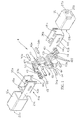
Fig. 1 shows a perspective view of constructional elements of the concealed hinge according to the invention; -
Figs. 2a and 2b show a first embodiment of the hinge according to the invention; and -
Figs. 3a and 3b show a second embodiment of the hinge according to the invention. - Referring to
Fig. 1 , a concealedhinge assembly 10 according to the present invention comprises a first and a secondouter shell concealed hinge 14. -
Outer shells - In the preferred embodiment, each
shell open end second end -
Shells concealed hinge 14 according to the invention and they have, associated with their second end, a securingmember Figs. 1 ,2a ,2b ,3a, 3b ), respectively, for instance a threaded member configured to allowhinge 14 to be secured to the shells by means of suitableremovable means - In the preferred embodiment,
hinge 14 includes a first and asecond end member 41a and 41b, respectively, which are preferably identical to each other and are shaped and sized so that they can be inserted into therespective shells - More particularly, end members or
inner shells 41a and 41b, respectively, are for instance substantially U-shaped and, in use, they are inserted in mirror-like manner in the respective outer shells and are connected to each other by means oflevers 42. As it will be disclosed in detail below, the levers are arranged to buildhinge 14 in combination with the first end member (first U-shaped member) 41a and the second end member (second U-shaped member) 41b. - In the preferred embodiment, each U-shaped
member 41a or 41b forms a wing of the hinge and has: - two
slots member 41a or 41b and are arranged to receive afirst pivot pin slots first pivot pin - two
holes second pivot pin - preferably, a
throughhole screw respective shell screws - In the preferred embodiment,
levers 42 have a leaf structure, with predetermined thickness; they are arranged, in use, to allow one lever to slide relative to another one, are identical to each other and have each three holes. - More particularly, levers 42 have:
- a
central hole 45 arranged to allow insertion of acentral pivot pin 55; in use,central pin 55 joins alllevers 42 in the hinge and acts as the central pivot forconcealed hinge 14; - two
holes respective ends first pins second pins - More particularly, in the preferred embodiment, in a first lever set 421, including e.g. three levers as shown in
Fig. 1 ,holes 43 of the first lever ends are pivotally mounted on thefirst pin 53a of the first U-shapedmember 41a, andholes 44 of the second lever ends are pivotally mounted on thesecond pin 53b of the second U-shaped member 41b. Moreover, in accordance with such an embodiment, levers 42 in the first set are kept separate from one another in correspondence of the pins by means ofsuitable washers 49 having a thickness corresponding to that oflevers 42. - Also in accordance with such an embodiment, a second lever set 422, including e.g. three levers as shown in
Fig. 1 , is arranged in mirrored manner with respect to the first lever set and so thatholes 43 of thefirst ends 53 are pivotally mounted on thesecond pin 54a of the second U-shaped member 41b, andholes 44 of the second ends are pivotally mounted on thesecond pin 54a of the first U-shapedmember 41a. Moreover, in accordance with such an embodiment, levers 42 in the second set are kept separate from one another in correspondence of the pins by means ofsuitable washers 49 having a thickness corresponding to that oflevers 42. - Both lever sets are pivotally connected to each other by means of
central pin 55 thereby forming a lever pack. - As the skilled in the art will readily appreciate, the shape of the levers determines the rotation angle of the hinge wings, which angle, in accordance with the present exemplary embodiment, may take any value in the range 0° to 180°.
- More particularly,
levers 42 are substantially C-shaped, with predetermined outer andinner profiles - As the skilled in the art will readily appreciate,
outer profile 42a has such a size that it does not interfere with the sizes ofshells -
Inner profile 42b has such a size that it limits the maximum rotation angle of the wings or U-shaped members associated withhinge shells Figs. 2a and 2b , showing a hinge with a maximum opening of 180°, and inFigs. 3a and 3b , showing a hinge with a maximum opening of 90°, the inner profile is configured to abut against thesecond pins 54a and/or 54b in fully opened conditions. - As far as the materials used for manufacturing
concealed hinge assembly 10 according to the present invention is concerned, iron-based materials are preferably used. - For instance, outer and inner shells can be made of iron plate, steel plate and so on. The levers, as well as the pins, can be made for instance of steel, stainless steel or other materials with high stiffness. The washers can be made of iron plate, steel plate and so on.
- As the skilled in the art will readily appreciate, assembling
hinge 14 andhinge assembly 10 includes for instance the following steps: - fastening the first lever set to the second lever set by inserting
central pin 55 intocentral hole 45 of the levers, thereby obtaining a lever pack; such step preferably includes alternately arranging the levers, with the ends facing in mirrored manner; - inserting the
first ends 53 of the first lever set into the first U-shaped member and inserting, throughslot pair 43a, thefirst pin 53a intoholes 43; preferably,washers 49 are also arranged betweenlevers 42; - inserting the
second ends 54 of the second lever set into the first U-shaped member and inserting, throughhole pair 44a, thesecond pin 54a intoholes 44a andholes 44 provided in thesecond ends 54 of the second lever set; preferably,washers 49 are also arranged betweenlevers 42; - inserting the first U-shaped member (first inner shell) 41a into
outer shell 12a and securing the inner shell to the outer shell by means ofscrew 35a and threadedmember 25a. - Once such operations have been completed, corresponding operations are performed for the second inner shell 41b, and this shell too is secured to
outer shell 12b by means ofscrew 35b and threadedmember 25b. - Once such operations have been completed, the concealed hinge is wholly assembled and inserted into the shells.
- The operation of the concealed hinge described above is as follows.
- Moving one of
wings 41a and/or 41b ofhinge 14 results in the first lever set rotating relative to the second lever set as long as the inner profiles of both lever sets, or the inner profile of at least one set, abut(s) against one of the second pivot pins 54a and/or 54b. - During rotation, the first pivot pins 53a and 53b slide in the
respective slot pair - As the skilled in the art will readily appreciate, the concealed hinge according to the invention is very solid and robust, since it comprises a plurality of levers arranged in facing relationship and mutually cooperating.
- In this manner, the load that can be supported depends to a great extent on the number and the size the levers mutually cooperating in the hinge.
- For instance, depending on the load, the first and/or the second lever sets may comprise at least two levers, and preferably the first set comprises as many levers as the second set.
- Obvious changes and modifications can be made to the above description in respect of sizes, shapes, materials, components, as well as in respect of the details of the illustrated construction and operating method, without departing from the spirit of the invention as set forth in the following claims.
Claims (9)
- A concealed hinge enabling rotation of one part of a structure relative to another part according to a predetermined limit angle, said hinge (14) including two opposite wings (41a, 41b) connectable to the respective parts of the structure in order to enable such rotation, the hinge being characterised by:- a plurality of levers (42) including a fist lever set (421) and a second lever set (422), said first set being pivotally connected to the second set so that the levers in the first set are arranged in mirrored manner with respect to the levers in the second set,
and being characterised in that each said wing (41a, 41b) has:- a pair of slots (43a, 43b) in which first ends (53) of said fist lever set (421) can be pivotally mounted; and- a pair of holes (44a, 44b) in which second ends (54) of said second lever set (422) can be pivotally mounted. - The hinge as claimed in claim 1, characterised in that said slots (43a, 43b) are straight slots.
- The hinge as claimed in claim 1 or 2, characterised in that said fist lever set is pivotally connected to the second set so that the levers in the first set are arranged alternate with the levers in the second set.
- The hinge as claimed in any of claims 1 to 3, characterised in that separating washers (49) are provided for the pivotal mounting of said first ends (53) of said fist lever set (421) into said pair of slots (43a, 43b) and/or of said second ends (54) of said second lever set (422) into said pair of holes (44a, 44b).
- The hinge as claimed in any of claims 1 to 4, characterised in that said levers (42) are substantially C-shaped and have an inner profile (42b) configured so as to determine the predetermined limit angle of the rotation of said wings (41a, 41b).
- The hinge as claimed in any of claims 1 to 4, characterised in that said levers (42) have a leaf structure.
- A concealed hinge assembly configured to enable rotation of one part of a structure relative to another part according to a predetermined limit angle, the assembly being characterised in that it comprises a concealed hinge (14) as claimed in claims 1 to 6, and a first and a second shell (12a, 12b) arranged to house the wings of said concealed hinge (14).
- A concealed hinge assembly, characterised in that removable securing means (35a, 35b) are provided in order to secure the wings of said concealed hinge (14) to said shells (12a, 12b).
- A method of manufacturing a concealed hinge (14) enabling rotation of one part of a structure relative another part, said hinge including two wings (41a, 41b) each having a pair of slots (43a, 43b) and a pair of holes (44a, 44b), the method comprising the steps of:- pivotally connecting a first and a second lever set so that the levers in the first set are arranged in mirrored manner with respect to the levers in the second set;- pivotally mounting first ends of said first lever set into a pair of slots in one of said wings;- pivotally mounting second ends of said second lever set into a pair of holes in said one wing.
Applications Claiming Priority (1)
| Application Number | Priority Date | Filing Date | Title |
|---|---|---|---|
| ITTO20080055 ITTO20080055A1 (en) | 2008-01-28 | 2008-01-28 | HIDDEN HINGE |
Publications (1)
| Publication Number | Publication Date |
|---|---|
| EP2083141A2 true EP2083141A2 (en) | 2009-07-29 |
Family
ID=40290408
Family Applications (1)
| Application Number | Title | Priority Date | Filing Date |
|---|---|---|---|
| EP20090151441 Withdrawn EP2083141A2 (en) | 2008-01-28 | 2009-01-27 | Concealed hinge |
Country Status (2)
| Country | Link |
|---|---|
| EP (1) | EP2083141A2 (en) |
| IT (1) | ITTO20080055A1 (en) |
Cited By (3)
| Publication number | Priority date | Publication date | Assignee | Title |
|---|---|---|---|---|
| ITPD20100022A1 (en) * | 2010-02-01 | 2011-08-02 | Oikos Venezia Srl | HINGE FOR DOORS, DOORS OR DOORS WITH HINGES IN GENERAL, WITH DISAPPEARANCE AND COMPLETE ROTATION |
| EP2476833A1 (en) * | 2011-01-12 | 2012-07-18 | Bartels Systembeschläge GmbH | Concealed hinge |
| EP4620793A1 (en) | 2024-03-18 | 2025-09-24 | Trieri Design d.o.o. | Concealed hinge with locking means for foldable vehicle |
Families Citing this family (1)
| Publication number | Priority date | Publication date | Assignee | Title |
|---|---|---|---|---|
| ITUB20160764A1 (en) | 2016-01-26 | 2017-07-26 | Stefano Ficco | HIDDEN HINGE EQUIPPED WITH TWO ROTATION AXES OPERATING IN SEQUENCE |
Citations (1)
| Publication number | Priority date | Publication date | Assignee | Title |
|---|---|---|---|---|
| EP1538290A2 (en) | 2003-12-05 | 2005-06-08 | Nova-Ferr S.r.l. | Concealed hinge |
-
2008
- 2008-01-28 IT ITTO20080055 patent/ITTO20080055A1/en unknown
-
2009
- 2009-01-27 EP EP20090151441 patent/EP2083141A2/en not_active Withdrawn
Patent Citations (1)
| Publication number | Priority date | Publication date | Assignee | Title |
|---|---|---|---|---|
| EP1538290A2 (en) | 2003-12-05 | 2005-06-08 | Nova-Ferr S.r.l. | Concealed hinge |
Cited By (4)
| Publication number | Priority date | Publication date | Assignee | Title |
|---|---|---|---|---|
| ITPD20100022A1 (en) * | 2010-02-01 | 2011-08-02 | Oikos Venezia Srl | HINGE FOR DOORS, DOORS OR DOORS WITH HINGES IN GENERAL, WITH DISAPPEARANCE AND COMPLETE ROTATION |
| EP2476833A1 (en) * | 2011-01-12 | 2012-07-18 | Bartels Systembeschläge GmbH | Concealed hinge |
| EP4620793A1 (en) | 2024-03-18 | 2025-09-24 | Trieri Design d.o.o. | Concealed hinge with locking means for foldable vehicle |
| WO2025195749A1 (en) | 2024-03-18 | 2025-09-25 | TRIERI DESIGN d.o.o. | Concealed hinge with locking means for foldable vehicle |
Also Published As
| Publication number | Publication date |
|---|---|
| ITTO20080055A1 (en) | 2009-07-29 |
Similar Documents
| Publication | Publication Date | Title |
|---|---|---|
| EP2902572B1 (en) | Device for moving members for operating or for closing a window or door frame | |
| EP2083141A2 (en) | Concealed hinge | |
| EP2899344B1 (en) | Hinge for furniture | |
| EP3211161A2 (en) | Fold-up window hardware | |
| CN115126364A (en) | Concealed external hinge rotating at 180 degrees | |
| PL199210B1 (en) | Subassembly with a hinge for doors, windows or similar | |
| GB2535637A (en) | Continuous hinge | |
| EP3480398A1 (en) | Connection system for the removable connection of an accessory for windows or doors | |
| JP5606058B2 (en) | Hidden hinge | |
| EP2687786A2 (en) | Assembly of a door hinge of an oven of a household appliance with dampened closing | |
| EP3141682B1 (en) | Adjustable hinge for vertically hanging panel | |
| CN113167087A (en) | Safety magnet hinge | |
| DE102020106690B3 (en) | Door hinge for building doors | |
| JP6333607B2 (en) | Handle and sliding door | |
| EP2886762A1 (en) | Multi-link hinge | |
| ITMI971288A1 (en) | HINGE FOR OVEN DOORS FOR ELECTRIC GAS, MICROWAVE OR SIMILAR COOKERS | |
| CN1763343B (en) | Hindge device | |
| CN207377330U (en) | A kind of concealed hinge | |
| EP1538290A2 (en) | Concealed hinge | |
| CN210460287U (en) | Hinge of super large door | |
| JP2009121134A (en) | Fitting | |
| FI129039B (en) | Hinge arrangement | |
| EP2520744A2 (en) | Handles for windows and doors | |
| CA2629662A1 (en) | Plug in pull bar hinge | |
| KR101195214B1 (en) | A hinge |
Legal Events
| Date | Code | Title | Description |
|---|---|---|---|
| PUAI | Public reference made under article 153(3) epc to a published international application that has entered the european phase |
Free format text: ORIGINAL CODE: 0009012 |
|
| AK | Designated contracting states |
Kind code of ref document: A2 Designated state(s): AT BE BG CH CY CZ DE DK EE ES FI FR GB GR HR HU IE IS IT LI LT LU LV MC MK MT NL NO PL PT RO SE SI SK TR |
|
| AX | Request for extension of the european patent |
Extension state: AL BA RS |
|
| STAA | Information on the status of an ep patent application or granted ep patent |
Free format text: STATUS: THE APPLICATION IS DEEMED TO BE WITHDRAWN |
|
| 18D | Application deemed to be withdrawn |
Effective date: 20130801 |