EP2083108A1 - Process for producing a metal hub of a washing machine and metal hub obtained through such process - Google Patents
Process for producing a metal hub of a washing machine and metal hub obtained through such process Download PDFInfo
- Publication number
- EP2083108A1 EP2083108A1 EP20080101020 EP08101020A EP2083108A1 EP 2083108 A1 EP2083108 A1 EP 2083108A1 EP 20080101020 EP20080101020 EP 20080101020 EP 08101020 A EP08101020 A EP 08101020A EP 2083108 A1 EP2083108 A1 EP 2083108A1
- Authority
- EP
- European Patent Office
- Prior art keywords
- tubular member
- hub
- metal
- washing machine
- metal tubular
- Prior art date
- Legal status (The legal status is an assumption and is not a legal conclusion. Google has not performed a legal analysis and makes no representation as to the accuracy of the status listed.)
- Withdrawn
Links
- 229910052751 metal Inorganic materials 0.000 title claims abstract description 23
- 239000002184 metal Substances 0.000 title claims abstract description 23
- 238000000034 method Methods 0.000 title claims abstract description 23
- 238000005406 washing Methods 0.000 title description 4
- 238000010412 laundry washing Methods 0.000 claims abstract description 8
- 229910000831 Steel Inorganic materials 0.000 claims abstract description 5
- 239000010959 steel Substances 0.000 claims abstract description 5
- 229910000975 Carbon steel Inorganic materials 0.000 claims description 3
- 239000010962 carbon steel Substances 0.000 claims description 3
- 229910001209 Low-carbon steel Inorganic materials 0.000 claims description 2
- 229920000642 polymer Polymers 0.000 description 5
- 229910052782 aluminium Inorganic materials 0.000 description 4
- XAGFODPZIPBFFR-UHFFFAOYSA-N aluminium Chemical compound [Al] XAGFODPZIPBFFR-UHFFFAOYSA-N 0.000 description 4
- 229910000838 Al alloy Inorganic materials 0.000 description 2
- 230000008878 coupling Effects 0.000 description 2
- 238000010168 coupling process Methods 0.000 description 2
- 238000005859 coupling reaction Methods 0.000 description 2
- 238000003754 machining Methods 0.000 description 2
- 229910001018 Cast iron Inorganic materials 0.000 description 1
- 238000010276 construction Methods 0.000 description 1
- 238000005520 cutting process Methods 0.000 description 1
- 239000007788 liquid Substances 0.000 description 1
- 238000004519 manufacturing process Methods 0.000 description 1
- 150000002739 metals Chemical class 0.000 description 1
Images

Classifications
-
- D—TEXTILES; PAPER
- D06—TREATMENT OF TEXTILES OR THE LIKE; LAUNDERING; FLEXIBLE MATERIALS NOT OTHERWISE PROVIDED FOR
- D06F—LAUNDERING, DRYING, IRONING, PRESSING OR FOLDING TEXTILE ARTICLES
- D06F37/00—Details specific to washing machines covered by groups D06F21/00 - D06F25/00
Definitions
- the present invention relates to a process for producing a metal tubular member acting as the central hub of a laundry washing machine and provided with seats for roller bearings adapted to be inserted in the tubular member and in which a drum shaft is supported.
- a metal tubular member acting as the central hub of a laundry washing machine and provided with seats for roller bearings adapted to be inserted in the tubular member and in which a drum shaft is supported.
- EP-A-43429 Examples of known metal tubular members constituting the hub of a laundry washing machine tub are shown in EP-A-43429 and in EP-A-198554 .
- the hub of EP-A-43429 presents a complicate tubular shape, with a longitudinal axis, with the purpose of containing a couple of ball bearings, which have to sustain the weight of the drum and the dynamic stress, transferred through the shaft, and transmitting all these stresses to the tub.
- Transversal ribs on the external surface of the hub avoid the relative movement between hub and tub.
- the hub is inserted into the mould in which it is covered by the plastic polymer that, in the same mould, forms the tub.
- this complicate shape has some negative aspects.
- the main object of the present invention is to provide a process for producing a hub, and a hub obtained trough such process, that will overcome all the above mentioned problems and will be simple and cost effective.
- the tubular hub is made of a metal that is the same of the ball bearings (steel).
- the hub is produced starting from a carbon steel tube with a process able to form, on the internal surface thereof, the two inner annular housings for the bearings, and on the external surface, a particular shape able to constrain the hub to the polymer of the tub in a reliable and secure manner so as to exclude any relative movement.
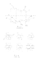
- a metal hub 1 is formed from an extruded low carbon steel tube by cutting it to the required length and subsequently, thanks to a bulge forming process shown in figure 4 , by forming at the two ends 11 and 12 the bearing housings.
- the cut down steel tube is inserted into a bulge forming machine with six stations, in which a couple of punches P perform a expansion of the two ends of the tube step by step, from the original diameter to the bearing housings diameter.
- the punches carry out a fine calibration of the dimensions and the abutments of the two bearing housings 11 a and 12a.
- the hub 1 is provided with an externally convergent-divergent shape which defines two truncated cone portions 13a and 13b with the purpose of excluding any relative movement in the direction of the longitudinal axis between the hub 1 and the plastic polymer of the tub (not shown).
- the roughness of the external surface of the hub 1, in contact with the plastic tub, is sufficient to prevent any movement thanks to the torsional friction.
- the knurled portion 14 ( figure 2 ) is preferably situated in the central portion of the hub 1, between the two truncated cone portions 13a and 13b.
- the knurled surface can be moved to other zones of the hub, or it can be extended on the entire outside surface of the hub.
- the ends 11, 12 of the hub provide, on its internal surface, the two inner annular housings for the bearings (not shown) with, respectively, the two abutments 11a and 12a for the same bearings obtained without the need for any machining process subsequent to the bulge forming of the hub.
- the hub according to the present invention can be used either in front loading washing machine or in top loading washing machine, and it can be also used not only for horizontal axis washers, but also for vertical axis washers.
Landscapes
- Engineering & Computer Science (AREA)
- Textile Engineering (AREA)
- Main Body Construction Of Washing Machines And Laundry Dryers (AREA)
Abstract
Description
- The present invention relates to a process for producing a metal tubular member acting as the central hub of a laundry washing machine and provided with seats for roller bearings adapted to be inserted in the tubular member and in which a drum shaft is supported. In laundry washing machines provided with a drum with horizontal or inclined axis, the rotation of the drum which holds the laundry and is contained by the tub, that doesn't take part to the rotation and contains the wash liquid, is guaranteed by providing in the rear part of the tub a hub which generally is buried into the plastic polymer of the tub.
- Examples of known metal tubular members constituting the hub of a laundry washing machine tub are shown in
EP-A-43429 EP-A-198554 EP-A-43429 - Generally, this problem can be overcome by using cast iron instead of aluminum, however with a high increase of cost.
- The same problems do exist in a metal hub of the type shown in
EP-A-198554 - The main object of the present invention is to provide a process for producing a hub, and a hub obtained trough such process, that will overcome all the above mentioned problems and will be simple and cost effective.
- The above object is reached by a process and by a hub according to the attached claims.
- One of the main advantages of the invention is that the tubular hub is made of a metal that is the same of the ball bearings (steel). According to the invention, the hub is produced starting from a carbon steel tube with a process able to form, on the internal surface thereof, the two inner annular housings for the bearings, and on the external surface, a particular shape able to constrain the hub to the polymer of the tub in a reliable and secure manner so as to exclude any relative movement.
- The invention will be clearer from the detailed description given hereinafter by way of example, with reference to the accompanying drawing in which:
-
Figure 1 is a prospective view of a typical aluminum hub according to prior art and obtained by a die cast process; -
Figure 2 is a lateral view of the hub of a washing machine according to the invention; -
Figure 3 is a section view along the longitudinal axis of the hub offigure 2 ; and -
Figure 4 illustrates schematically a process sequence to realize the hub according to the invention. - With reference to the drawings, a metal hub 1 is formed from an extruded low carbon steel tube by cutting it to the required length and subsequently, thanks to a bulge forming process shown in
figure 4 , by forming at the twoends 11 and 12 the bearing housings. - In the metal forming process of the hub according to the invention, the cut down steel tube is inserted into a bulge forming machine with six stations, in which a couple of punches P perform a expansion of the two ends of the tube step by step, from the original diameter to the bearing housings diameter. In the last step the punches carry out a fine calibration of the dimensions and the abutments of the two bearing housings 11 a and 12a.
- At the end of the forming process, the hub 1 is provided with an externally convergent-divergent shape which defines two truncated cone portions 13a and 13b with the purpose of excluding any relative movement in the direction of the longitudinal axis between the hub 1 and the plastic polymer of the tub (not shown). The roughness of the external surface of the hub 1, in contact with the plastic tub, is sufficient to prevent any movement thanks to the torsional friction. However, it is preferred to add a knurl process to the overall metal forming process in order to obtain a knurled
portion 14 on the external surface in order to increase the torsional coupling. The knurled portion 14 (figure 2 ) is preferably situated in the central portion of the hub 1, between the two truncated cone portions 13a and 13b. Of course the knurled surface can be moved to other zones of the hub, or it can be extended on the entire outside surface of the hub. - The
ends 11, 12 of the hub provide, on its internal surface, the two inner annular housings for the bearings (not shown) with, respectively, the two abutments 11a and 12a for the same bearings obtained without the need for any machining process subsequent to the bulge forming of the hub. However, it is possible to add a machining process in order to obtain better tolerances and roughness for the two bearinghousings 11, 12 and abutments. - The hub according to the present invention can be used either in front loading washing machine or in top loading washing machine, and it can be also used not only for horizontal axis washers, but also for vertical axis washers.
Claims (8)
- Process for producing a metal tubular member (1) to be used as a hub of a laundry washing machine, characterized in that it comprises the following steps:- providing a steel tube portion, and- expanding the two ends of the tube portion through a metal forming process with punches (P) so that such expanded ends (11, 12) are adapted for mounting roller bearings for supporting a drum shaft in the tubular member (1).
- Process according to claim 1, wherein the expansion of the two ends (11, 12) is such that the tubular member (1) presents two truncated cone-shaped portions (13a, 13b) diverging from a central zone of the member (1).
- Process according to claim 1 or 2, wherein the steel tube portion is obtained from an extruded low carbon steel tube.
- Process according to any of the preceding claims, wherein it comprises a knurling process of at least a portion (14) of the outside surface of the metal tubular member (1).
- Laundry washing machine provided with a metal tubular member (1) for rotatably supporting the drum shaft obtained through a process according to any of the preceding claims.
- Metal tubular member (1) to be used as hub of a laundry washing machine and provided with seats (11, 12, 11a, 12a) for roller bearings adapted to be mounted in the tubular member (1) and in which a drum shaft has to be rotatably supported, characterized in that the metal tubular member (1) is made of carbon steel and presents two truncated cone-shaped portions (13a, 13b) diverging from a central zone of such member (1).
- Metal tubular member according to claim 6, wherein a central zone of the metal tubular member (1) presents an outside knurled surface.
- Metal tubular member according to claim 7, wherein the central knurled portion (14) is cylindrical.
Priority Applications (1)
| Application Number | Priority Date | Filing Date | Title |
|---|---|---|---|
| EP20080101020 EP2083108A1 (en) | 2008-01-28 | 2008-01-28 | Process for producing a metal hub of a washing machine and metal hub obtained through such process |
Applications Claiming Priority (1)
| Application Number | Priority Date | Filing Date | Title |
|---|---|---|---|
| EP20080101020 EP2083108A1 (en) | 2008-01-28 | 2008-01-28 | Process for producing a metal hub of a washing machine and metal hub obtained through such process |
Publications (1)
| Publication Number | Publication Date |
|---|---|
| EP2083108A1 true EP2083108A1 (en) | 2009-07-29 |
Family
ID=39684275
Family Applications (1)
| Application Number | Title | Priority Date | Filing Date |
|---|---|---|---|
| EP20080101020 Withdrawn EP2083108A1 (en) | 2008-01-28 | 2008-01-28 | Process for producing a metal hub of a washing machine and metal hub obtained through such process |
Country Status (1)
| Country | Link |
|---|---|
| EP (1) | EP2083108A1 (en) |
Cited By (2)
| Publication number | Priority date | Publication date | Assignee | Title |
|---|---|---|---|---|
| EP2433719A2 (en) | 2010-08-27 | 2012-03-28 | Vestel Beyaz Esya Sanayi Ve Ticaret A.S. | Apparatus for production of bearing housing |
| EP2460923A3 (en) * | 2010-12-06 | 2012-10-03 | BSH Bosch und Siemens Hausgeräte GmbH | Washing machine bearing hub |
Citations (6)
| Publication number | Priority date | Publication date | Assignee | Title |
|---|---|---|---|---|
| EP0043429A1 (en) | 1980-07-03 | 1982-01-13 | INDUSTRIE ZANUSSI S.p.A. | Wash tub of plastics material for clothes washing machines |
| EP0198554A2 (en) | 1985-04-17 | 1986-10-22 | Whirlpool International B.V. | Tub with a tubular hub made rigid therewith by through formations of engineering polymer, for laundry washing machines with a drum of horizontal axis |
| EP0321030A1 (en) | 1987-12-15 | 1989-06-21 | Whirlpool International B.V. | Seal-joint member, particularly for a washing machine tub assembly |
| EP0789103A2 (en) * | 1996-01-31 | 1997-08-13 | Balay S.A. | Improvement in plastic tank for washing machine |
| DE10045181C1 (en) * | 2000-09-13 | 2001-12-13 | Whirlpool Co | Front-loading washing machine has bearing hub of washing liquid drum acting as imbalance compensation weight |
| WO2004042133A1 (en) | 2002-11-06 | 2004-05-21 | BSH Bosch und Siemens Hausgeräte GmbH | Plastic receptacle for domestic washing machines |
-
2008
- 2008-01-28 EP EP20080101020 patent/EP2083108A1/en not_active Withdrawn
Patent Citations (6)
| Publication number | Priority date | Publication date | Assignee | Title |
|---|---|---|---|---|
| EP0043429A1 (en) | 1980-07-03 | 1982-01-13 | INDUSTRIE ZANUSSI S.p.A. | Wash tub of plastics material for clothes washing machines |
| EP0198554A2 (en) | 1985-04-17 | 1986-10-22 | Whirlpool International B.V. | Tub with a tubular hub made rigid therewith by through formations of engineering polymer, for laundry washing machines with a drum of horizontal axis |
| EP0321030A1 (en) | 1987-12-15 | 1989-06-21 | Whirlpool International B.V. | Seal-joint member, particularly for a washing machine tub assembly |
| EP0789103A2 (en) * | 1996-01-31 | 1997-08-13 | Balay S.A. | Improvement in plastic tank for washing machine |
| DE10045181C1 (en) * | 2000-09-13 | 2001-12-13 | Whirlpool Co | Front-loading washing machine has bearing hub of washing liquid drum acting as imbalance compensation weight |
| WO2004042133A1 (en) | 2002-11-06 | 2004-05-21 | BSH Bosch und Siemens Hausgeräte GmbH | Plastic receptacle for domestic washing machines |
Cited By (2)
| Publication number | Priority date | Publication date | Assignee | Title |
|---|---|---|---|---|
| EP2433719A2 (en) | 2010-08-27 | 2012-03-28 | Vestel Beyaz Esya Sanayi Ve Ticaret A.S. | Apparatus for production of bearing housing |
| EP2460923A3 (en) * | 2010-12-06 | 2012-10-03 | BSH Bosch und Siemens Hausgeräte GmbH | Washing machine bearing hub |
Similar Documents
| Publication | Publication Date | Title |
|---|---|---|
| CN104191166B (en) | A kind of roll-forming method of aluminium alloy height cylinder thin-walled ring | |
| CN105090216A (en) | Blind nut | |
| US10302122B2 (en) | Balance shaft | |
| JP2016502478A (en) | Hydroformed driveshaft tube with secondary shape | |
| EP2083108A1 (en) | Process for producing a metal hub of a washing machine and metal hub obtained through such process | |
| CN104246312A (en) | Component for a planetary gear train | |
| EP2447555B1 (en) | Oil-impregnated sintered bearing and method of manufacturing the same | |
| US7836592B2 (en) | Method of producing connecting rod with bearing | |
| JP2017511454A (en) | Lightweight drive axle shaft | |
| JP6264652B2 (en) | Automotive knuckle | |
| JP4989742B2 (en) | Wiper device | |
| CN213436365U (en) | Hydraulic cold drawing mechanism for stainless steel seamless steel pipe | |
| US20070245798A1 (en) | Integral Axle Housing for Vehicle and Method of Manufacture the Same | |
| CN212577850U (en) | Thin-wall shell machining device | |
| CN104632903A (en) | Bearing-hub assembly with a light alloy hub | |
| JP2010099729A (en) | Sequential forming apparatus and its method | |
| EP1993900B1 (en) | Bicycle pedal crank with biomechanic lever varying device for | |
| CN215567210U (en) | Novel miniature axle of annular knurl ladder | |
| KR102779335B1 (en) | Bearing and steering apparatus having the same | |
| CN220101802U (en) | Bearing multi-body combined bearing | |
| CN221362019U (en) | Vertical roll structure of welding pipe forming sizing mill | |
| CN101761551A (en) | Light cylindrical roller bearing | |
| JP2007255536A (en) | Tapered roller bearing, spacer, and spindle supporting structure of wind power generator | |
| JP2009179079A (en) | Wiper device | |
| US11091187B2 (en) | Spindle and steering column assembly having same |
Legal Events
| Date | Code | Title | Description |
|---|---|---|---|
| PUAI | Public reference made under article 153(3) epc to a published international application that has entered the european phase |
Free format text: ORIGINAL CODE: 0009012 |
|
| AK | Designated contracting states |
Kind code of ref document: A1 Designated state(s): AT BE BG CH CY CZ DE DK EE ES FI FR GB GR HR HU IE IS IT LI LT LU LV MC MT NL NO PL PT RO SE SI SK TR |
|
| AX | Request for extension of the european patent |
Extension state: AL BA MK RS |
|
| 17P | Request for examination filed |
Effective date: 20100115 |
|
| 17Q | First examination report despatched |
Effective date: 20100208 |
|
| AKX | Designation fees paid |
Designated state(s): DE ES FR GB IT PL |
|
| STAA | Information on the status of an ep patent application or granted ep patent |
Free format text: STATUS: THE APPLICATION IS DEEMED TO BE WITHDRAWN |
|
| 18D | Application deemed to be withdrawn |
Effective date: 20151124 |