EP2082850A2 - Generating device of processing robot program - Google Patents
Generating device of processing robot program Download PDFInfo
- Publication number
- EP2082850A2 EP2082850A2 EP08020097A EP08020097A EP2082850A2 EP 2082850 A2 EP2082850 A2 EP 2082850A2 EP 08020097 A EP08020097 A EP 08020097A EP 08020097 A EP08020097 A EP 08020097A EP 2082850 A2 EP2082850 A2 EP 2082850A2
- Authority
- EP
- European Patent Office
- Prior art keywords
- workpiece
- vision sensor
- robot
- orientation
- processing
- Prior art date
- Legal status (The legal status is an assumption and is not a legal conclusion. Google has not performed a legal analysis and makes no representation as to the accuracy of the status listed.)
- Granted
Links
Images






Classifications
-
- B—PERFORMING OPERATIONS; TRANSPORTING
- B25—HAND TOOLS; PORTABLE POWER-DRIVEN TOOLS; MANIPULATORS
- B25J—MANIPULATORS; CHAMBERS PROVIDED WITH MANIPULATION DEVICES
- B25J9/00—Program-controlled manipulators
- B25J9/16—Program controls
- B25J9/1694—Program controls characterised by use of sensors other than normal servo-feedback from position, speed or acceleration sensors, perception control, multi-sensor controlled systems, sensor fusion
- B25J9/1697—Vision controlled systems
-
- G—PHYSICS
- G05—CONTROLLING; REGULATING
- G05B—CONTROL OR REGULATING SYSTEMS IN GENERAL; FUNCTIONAL ELEMENTS OF SUCH SYSTEMS; MONITORING OR TESTING ARRANGEMENTS FOR SUCH SYSTEMS OR ELEMENTS
- G05B19/00—Program-control systems
- G05B19/02—Program-control systems electric
- G05B19/18—Numerical control [NC], i.e. automatically operating machines, in particular machine tools, e.g. in a manufacturing environment, so as to execute positioning, movement or co-ordinated operations by means of program data in numerical form
- G05B19/408—Numerical control [NC], i.e. automatically operating machines, in particular machine tools, e.g. in a manufacturing environment, so as to execute positioning, movement or co-ordinated operations by means of program data in numerical form characterised by data handling or data format, e.g. reading, buffering or conversion of data
- G05B19/4083—Adapting program, configuration
-
- G—PHYSICS
- G05—CONTROLLING; REGULATING
- G05B—CONTROL OR REGULATING SYSTEMS IN GENERAL; FUNCTIONAL ELEMENTS OF SUCH SYSTEMS; MONITORING OR TESTING ARRANGEMENTS FOR SUCH SYSTEMS OR ELEMENTS
- G05B2219/00—Program-control systems
- G05B2219/30—Nc systems
- G05B2219/35—Nc in input of data, input till input file format
- G05B2219/35012—Cad cam
-
- G—PHYSICS
- G05—CONTROLLING; REGULATING
- G05B—CONTROL OR REGULATING SYSTEMS IN GENERAL; FUNCTIONAL ELEMENTS OF SUCH SYSTEMS; MONITORING OR TESTING ARRANGEMENTS FOR SUCH SYSTEMS OR ELEMENTS
- G05B2219/00—Program-control systems
- G05B2219/30—Nc systems
- G05B2219/36—Nc in input of data, input key till input tape
- G05B2219/36504—Adapt program to real coordinates, shape, dimension of tool, offset path
-
- G—PHYSICS
- G05—CONTROLLING; REGULATING
- G05B—CONTROL OR REGULATING SYSTEMS IN GENERAL; FUNCTIONAL ELEMENTS OF SUCH SYSTEMS; MONITORING OR TESTING ARRANGEMENTS FOR SUCH SYSTEMS OR ELEMENTS
- G05B2219/00—Program-control systems
- G05B2219/30—Nc systems
- G05B2219/37—Measurements
- G05B2219/37555—Camera detects orientation, position workpiece, points of workpiece
-
- G—PHYSICS
- G05—CONTROLLING; REGULATING
- G05B—CONTROL OR REGULATING SYSTEMS IN GENERAL; FUNCTIONAL ELEMENTS OF SUCH SYSTEMS; MONITORING OR TESTING ARRANGEMENTS FOR SUCH SYSTEMS OR ELEMENTS
- G05B2219/00—Program-control systems
- G05B2219/30—Nc systems
- G05B2219/45—Nc applications
- G05B2219/45058—Grinding, polishing robot
-
- Y—GENERAL TAGGING OF NEW TECHNOLOGICAL DEVELOPMENTS; GENERAL TAGGING OF CROSS-SECTIONAL TECHNOLOGIES SPANNING OVER SEVERAL SECTIONS OF THE IPC; TECHNICAL SUBJECTS COVERED BY FORMER USPC CROSS-REFERENCE ART COLLECTIONS [XRACs] AND DIGESTS
- Y02—TECHNOLOGIES OR APPLICATIONS FOR MITIGATION OR ADAPTATION AGAINST CLIMATE CHANGE
- Y02P—CLIMATE CHANGE MITIGATION TECHNOLOGIES IN THE PRODUCTION OR PROCESSING OF GOODS
- Y02P90/00—Enabling technologies with a potential contribution to greenhouse gas [GHG] emissions mitigation
- Y02P90/02—Total factory control, e.g. smart factories, flexible manufacturing systems [FMS] or integrated manufacturing systems [IMS]
Definitions
- the present invention relates to a generating device of a processing robot program for carrying out processing such as burring, by using a robot.
- the vision sensor captures an image of the shape of the workpiece. Then, the difference in the images between the detected workpiece and a reference workpiece is calculated, by which each teaching position in a processing program is corrected in order to accommodate a positional error of the workpiece.
- the position and orientation of the robot, where the vision sensor may capture the workpiece is finely adjusted by an operation such as a jog operation, in order to make a program for moving the robot to the imaging position.
- a vision sensor does not detect the height of a surface of the workpiece to be processed relative to a reference surface, and the workpiece may be processed without correcting the position and orientation of a tool of a robot.
- Japanese Unexamined Patent Publication (Kokai) No. 5-31659 discloses a burring device and method capable of visually recognizing only a region of a workpiece where a burr may be generated, by utilizing design information of an ideal shape of the workpiece.
- Japanese Unexamined Patent Publication (Kokai) No. 5-31659 also discloses a technique to generate a robot path based on drawing information including a free curve portion generated by a CAD system or the like, in order to simply an operation offline.
- Japanese Unexamined Patent Publication (Kokai) No. 5-233048 discloses a technique to generate path teaching data for carrying out burring/polishing against various types of workpiece having a complicated ridge line.
- the tool may interfere with the workpiece and therefore the tool cannot process the workpiece.
- an object of the present invention is to provide a generation device of a processing robot program used in a robot system having a vision sensor, capable of accommodating an error in the shape of a workpiece and reducing man-hours required for a teaching operation.
- a generating device of a processing robot program by which three-dimensional models of a robot, a workpiece and a vision sensor are displayed on a display and the robot processes the workpiece
- the generating device comprising: a processing line assigning part for assigning a processing line on the three-dimensional model of the workpiece on the display; a processing line dividing part for dividing the processing line into a plurality of line segments; a detection area determining part for determining a plurality of detection areas, each including each segment obtained by the processing line dividing part, within a graphic image obtained by capturing the three-dimensional model of the workpiece by using the three-dimensional model of the vision sensor as a virtual camera; a teaching point generating part for generating a teaching point by which each segment of the processing line divided by the processing line dividing part is processed; a detection model generating part for generating an image detection model in each detection area based on the graphic image, such that the vision sensor may detect each detection area of the graphic image determined by the detection area
- the generating device may further comprise a program generating part for generating an imager movement robot program wherein the program generating part being capable of assigning the three-dimensional model of the workpiece so as to move the robot to a position where the vision sensor mounted to the robot can capture the workpiece to be processed; moving the robot to a position and orientation so that the orientation of the vision sensor is parallel to a surface of the three dimensional model to be processed; calculating the position and orientation of the robot in which the vision sensor captures the center of the three dimensional model of the workpiece, based on the positional relationship between the three dimensional models of the vision sensor and the workpiece; and generating a teaching point by which the vision sensor captures the whole of the three dimensional model of the workpiece.
- the generating device may further comprise an automatic adjusting part for automatically adjusting the position and orientation of the teaching point by detecting the height of the surface of the workpiece to be processed from a reference surface of the workpiece by means of the vision sensor.
- a robot program generating device for processing may be a personal computer (hereinafter, referred to as a "PC") as schematically shown in Fig. 1 .
- PC 10 has a display 12 capable indicating three-dimensional models of a robot 14, a tool 16 attached to robot 14 for processing, a workpiece 18 to be processed, a pedestal or a jig 20 for loading workpiece 18 thereon, and a vision sensor 22 having a virtual camera for imaging workpiece 18 in PC 10.
- Display 12 of PC 10 can also indicate a graphic image of a three-dimensional model of workpiece 18 (in an illustrated embodiment, an image of workpiece 18 viewed from the above) captured by virtual camera 22.
- workpiece 18 has features, for example two holes 26, for differentiating it from other workpieces.
- Workpiece 18 also has a processing line 28 or a site to be processed, which is used when the workpiece is processed (for example, burred) by using tool 16.
- step S1 three-dimensional models of elements such as robot 14 are indicated or located on the display so as to make a layout as shown in Fig. 1 .
- step S2 a processing line 28 is assigned on workpiece 18 which is used when the workpiece is actually processed by tool 16.
- processing line 28 is divided into a plurality of line segments based on the shape of the processing line, as shown in Fig. 3 .
- processing line 28 is divided into segments each having a simple shape, such as a corner, a straight line and/or a curved line.
- processing line 28 is divided into four straight line segments 28a and four rounded corner segments 28b.
- step S4 in the layout as described above, a graphic image of workpiece 18 viewed from virtual camera 22 is indicated on the display. Then, detection areas are determined in the graphic image viewed from virtual camera 22 such that each segment of the processing line generated in step S3 is included in the detection areas (step S5). At this point, since a teaching point included in the processing line is corrected in each divided segment as described below, it is preferable that there is a one-on-one relationship between each detection area and each segment.
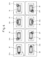
- image detection models each including each detection area, are generated in graphic image 24 of workpiece 18 viewed from virtual camera 22, as shown in Fig. 4 .
- the image detection models includes a model 30 for detecting features or holes 26, and models 32a to 32h for detecting each detection area.
- a processing program including data of teaching points for processing the segments of processing line 28 of workpiece 18 as shown in Fig. 5 .
- one teaching point is set to each straight line segment 28 and three teaching points are set to each corner segment.
- a processing program including a command line assigning the position of each teaching point and a processing speed at each teaching point, etc., is generated.
- the teaching points may be automatically set corresponding to the shape of each segment, otherwise, may be timely input by an operation such as a mouse click motion by an operator.
- a detection program is generated, by which a workpiece 18' to be processed is actually imaged or captured by a vision sensor such as a camera 22' corresponding to virtual camera 22, in the similar positional relationship of the layout as generated in step S1, as shown in Fig. 6 , and the position and orientation of each segment of workpiece 18' corresponding to each detection model generated in step S6 are detected. Further, a command line for calling the detection program is inserted into the above processing program.
- Fig. 6 shows an image obtained by the vision sensor and an example of a program into which the detection program (in the example, named as "VISION”) is inserted.
- a command line for calculating and obtaining an amount of change or a difference between the detection model and the actually captured image of the workpiece by the vision sensor, in relation to the position and the orientation of each segment, is generated and added to the processing program.
- There are two methods for calculating and obtaining the amount of change i.e., a method for obtaining correction data as the amount of change of the position and orientation, by a command in a detection program for detecting the position and orientation of each segment of the workpiece; and another method for generating a calculation program (for example, named as "CALC") for calculating the position and orientation of each segment as shown in Fig. 7 , and inserting a command calling the calculation program into the processing program.
- a calculation program for example, named as "CALC"
- step S10 based on the amount of change calculated in step S9, a correction program is inserted into the processing program, the correction program being capable of correcting the teaching point for processing each segment such as a corner or a straight line. Due to this, an actual trajectory of the tool relative to the workpiece at each segment is corrected.
- the amount of change of the position and orientation is calculated by comparing the image detection model of the three-dimensional model of the workpiece obtained by the virtual camera to the image of the workpiece actually captured by the vision sensor, and then the teaching point is corrected based on the amount of change. Therefore, even when the actual workpiece has a shape error, the shape error may be accommodated and the workpiece may be correctly processed along a desired processing line, whereby a processing accuracy of the workpiece may be significantly improved.
- the robot for carrying out processing and the vision sensor for capturing the workpiece are independently arranged.
- an imager such as a camera 22 may be attached to a robot 12 for processing a workpiece 18, whereby the position of the camera may be adjusted.
- the processing program of the invention may further generate an imager movement program using the robot.
- the procedure for generating the movement program will be explained with reference to a flowchart as shown in Fig. 9 .
- step S21 a three-dimensional model of a workpiece is assigned in PC 10. This assignment may be executed, for example, by mouse-clicking a workpiece to be assigned among workpieces indicated on display 12.
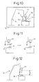
- a robot 14 is moved relative to a assigned workpiece 18 such that a virtual camera 22 of a vision sensor attached to a front end of a hand of the robot is moved generally directly above workpiece 18 and the orientation of virtual camera 22 is parallel to a processing surface 34 of workpiece 18, as shown in fig. 10 .
- a calibration by which camera 22 may present the above position and orientation is executed based on an user coordinate system 36 (In Fig. 10 , only X- and Z-axes are schematically indicated) including a X-Y plane parallel to processing surface 34.
- a graphic image of the three-dimensional model of workpiece 18 viewed from virtual camera 22 is indicated on display 12 of PC 10 (step S23), and the horizontal position of virtual camera 22 is adjusted such that processing surface 34 of the workpiece is positioned at the center of the image (step S24).
- a gap or displacement "d" between the center coordinate (for example, the center of gravity) of processing surface 34 and the center of an image obtained by virtual camera 22 (for example, the center of a lens of the camera) is calculated, and then the position and orientation of the robot are determined such that the center coordinate of processing surface 34 is positioned at the center of the graphic image of the three-dimensional model of workpiece 18 viewed from virtual camera 22.
- the height of the position of virtual camera 22 is adjusted to a predetermined value "h" by operating robot 14.
- the height "h,” defined as the distance from processing surface 34 to virtual camera 22, is predetermined such that virtual camera 22 can capture the whole of workpiece 18.
- the height "h” may be set by a user or operator, otherwise, may be determined based on a calculation or an experience.
- an imager movement program for moving robot 14 to the determined position and orientation is generated. Further, a teaching point is generated in relation to the determined position and orientation (step S26).
- a command or a program for capturing and detecting a workpiece to be imaged by using an actual vision sensor such as a camera is generated (step S27), and then the command or the program is inserted into the imager movement program.
- step S31 a processing line 28 of a workpiece 18 is assigned similarly in step S2 as described above, and then a processing program including data of a teaching point on processing line is generated. Similarly to the example of Fig. 5 , three teaching points are set to the corner segment and one teaching point is set to the straight line segment. Then, a processing program, including a command line assigning the position of each teaching point and a processing speed at each teaching point, etc., is generated.
- a graphic image of the three-dimensional model of workpiece 18 viewed from virtual camera 22 is indicated on display 12 of PC 10.
- the positional relationship between the virtual camera and the workpiece may be the same as shown in Fig. 1 .
- an image detection model having a reference surface and a processing surface of workpiece 18 is generated, on a graphic image model 24 of the three-dimensional model of the workpiece viewed from virtual camera 22.
- the image detection models includes a model 40 for detecting features or holes 26 of graphic image 24, a model 42 for detecting a processing surface 34 of the workpiece, and a model 44 for detecting a reference surface 38 of the workpiece.
- the height of the position of processing surface 34 relative to reference surface 38 may be obtained by using the three-dimensional model of the workpiece.
- a command or a program is generated, by which a workpiece 18' to be processed is actually imaged or captured by a vision sensor such as a camera 22', as shown in Fig. 16 , and the reference surface and the processing surface of workpiece 18' corresponding to each detection model generated in step S33 are detected from a captured image 24' obtained by camera 22'. Further, the generated command or the program thus generated is inserted into the processing program.
- a command or a program for calculating the heights of the positions of the reference surface and the processing surface of the workpiece to be processed, is generated.
- the difference of the sizes or the amount of change between an image of the workpiece actually capture by using vision sensor 22' ( Fig. 16 ) and the image detection model obtained by the virtual camera ( Fig. 15 ) is calculated, in relation to each of the reference surface and the processing surface, and the size is converted into the height.
- step S36 the teaching point in the processing program is corrected based on the calculation result.
- the height of the position of each teaching point in the processing program is corrected such that tool 16 contacts processing surface 34 of workpiece 18, based on the calculated height of the position of the processing surface.
- a clearance between a tool front point 16a of tool 16 and reference surface 38 of workpiece 18 is calculated based on the height of the position of the reference surface.
- a predetermined threshold e.g., as indicated in Fig. 17a by a solid line
- the tool may interfere with the reference surface in the actual processing. Therefore, as shown in Fig. 17b , the orientation of tool 16 at each teaching point is corrected (step S37), in order to make a clearance, between the tool and the reference surface, which is equal to or larger than the predetermined threshold.
- program generating device 10 of the invention has a processing line assigning part 10a for assigning a processing line on the three-dimensional model of the workpiece on the display; a processing line dividing part 10b for dividing the processing line into a plurality of line segments; a detection area determining part 10c for determining a plurality of detection areas, each including each segment obtained by the processing line dividing part, within a graphic image obtained by capturing the three-dimensional model of the workpiece by using the three-dimensional model of the vision sensor as a virtual camera; a teaching point generating part 10d for generating a teaching point by which each segment of the processing line divided by processing line dividing part 10b is processed; a detection model generating part 10e for generating an image detection model in each detection area based on the graphic image, such that the vision sensor may detect each detection area of the graphic image determined by detection area determining part 10c; a detecting part 10f for reading an image obtained by actually capturing a workpiece to be processed by
- Generating device 10 may further comprise a program generating part 10i for generating an imager movement robot program wherein the program generating part 10i being capable of assigning the three-dimensional model of the workpiece so as to move the robot to a position where the vision sensor mounted to the robot can capture the workpiece to be processed; moving the robot to a position and orientation so that the orientation of the vision sensor is parallel to a surface of the three dimensional model to be processed; calculating the position and orientation of the robot in which the vision sensor captures the center of the three dimensional model of the workpiece, based on the positional relationship between the three dimensional models of the vision sensor and the workpiece; and generating a teaching point by which the vision sensor captures the whole of the three dimensional model of the workpiece.
- Generating device may further comprise an automatic adjusting part 10j for automatically adjusting the position and orientation of the teaching point by detecting the height of the surface of the workpiece to be processed from a reference surface of the workpiece by means of the vision sensor.
- the vision sensor attached to the robot may be used to generate a teaching point for capturing the workpiece, whereby man-hours required for the teaching operation may be significantly reduced.
Landscapes
- Engineering & Computer Science (AREA)
- Robotics (AREA)
- Mechanical Engineering (AREA)
- Human Computer Interaction (AREA)
- Manufacturing & Machinery (AREA)
- Physics & Mathematics (AREA)
- General Physics & Mathematics (AREA)
- Automation & Control Theory (AREA)
- Numerical Control (AREA)
- Manipulator (AREA)
Abstract
Description
- The present application claims priority from Japanese Patent Application No.
2008-12736, filed on January 23, 2008 - The present invention relates to a generating device of a processing robot program for carrying out processing such as burring, by using a robot.
- In the prior art, when a workpiece is processed after the position and orientation of the workpiece is detected in a robot system having a vision sensor, the vision sensor captures an image of the shape of the workpiece. Then, the difference in the images between the detected workpiece and a reference workpiece is calculated, by which each teaching position in a processing program is corrected in order to accommodate a positional error of the workpiece.
- In some techniques, when the workpiece is captured by a vision sensor attached to a robot, the position and orientation of the robot, where the vision sensor may capture the workpiece, is finely adjusted by an operation such as a jog operation, in order to make a program for moving the robot to the imaging position. In some other techniques, a vision sensor does not detect the height of a surface of the workpiece to be processed relative to a reference surface, and the workpiece may be processed without correcting the position and orientation of a tool of a robot.
- Various techniques, regarding burring using a robot, have been proposed. For example, Japanese Unexamined Patent Publication (Kokai) No.
5-31659 5-31659 5-233048 - In the prior art, it is possible to detect the position and orientation of a workpiece by means of a vision sensor, in order to process the workpiece in view of a positional error of the workpiece. However, it is not possible to process the workpiece in view of a manufacturing error or an error in the shape of the workpiece. Therefore, it is difficult to process the workpiece while the tool of the robot precisely traces the shape of the workpiece.
- When the workpiece is captured by a vision sensor attached to a robot, it is necessary to finely adjust the position and orientation of the robot in order to determine the imaging position, which requires many man-hours.
- Further, when the workpiece is processed without correcting the position and orientation of the tool of the robot, the tool may interfere with the workpiece and therefore the tool cannot process the workpiece.
- Accordingly, an object of the present invention is to provide a generation device of a processing robot program used in a robot system having a vision sensor, capable of accommodating an error in the shape of a workpiece and reducing man-hours required for a teaching operation.
- According to the present invention, there is provided a generating device of a processing robot program, by which three-dimensional models of a robot, a workpiece and a vision sensor are displayed on a display and the robot processes the workpiece, the generating device comprising: a processing line assigning part for assigning a processing line on the three-dimensional model of the workpiece on the display; a processing line dividing part for dividing the processing line into a plurality of line segments; a detection area determining part for determining a plurality of detection areas, each including each segment obtained by the processing line dividing part, within a graphic image obtained by capturing the three-dimensional model of the workpiece by using the three-dimensional model of the vision sensor as a virtual camera; a teaching point generating part for generating a teaching point by which each segment of the processing line divided by the processing line dividing part is processed; a detection model generating part for generating an image detection model in each detection area based on the graphic image, such that the vision sensor may detect each detection area of the graphic image determined by the detection area determining part; a detecting part for reading an image obtained by actually capturing a workpiece to be processed by using a vision sensor, and detecting the position and the orientation of a portion of the workpiece corresponding to the image detection model; a change calculating part for calculating an amount of change between the position and the orientation of each image detection model and the position and the orientation of each teaching point included in the detection area corresponding to the image detection model; and a correcting part for correcting the position and the orientation of the teaching point included in the detection area corresponding to the image detection model, based on the amount of change.
- The generating device may further comprise a program generating part for generating an imager movement robot program wherein the program generating part being capable of assigning the three-dimensional model of the workpiece so as to move the robot to a position where the vision sensor mounted to the robot can capture the workpiece to be processed; moving the robot to a position and orientation so that the orientation of the vision sensor is parallel to a surface of the three dimensional model to be processed; calculating the position and orientation of the robot in which the vision sensor captures the center of the three dimensional model of the workpiece, based on the positional relationship between the three dimensional models of the vision sensor and the workpiece; and generating a teaching point by which the vision sensor captures the whole of the three dimensional model of the workpiece.
- The generating device may further comprise an automatic adjusting part for automatically adjusting the position and orientation of the teaching point by detecting the height of the surface of the workpiece to be processed from a reference surface of the workpiece by means of the vision sensor.
- The above and other objects, features and advantages of the present invention will be made more apparent by the following description of the preferred embodiments thereof, with reference to the accompanying drawings, wherein:
-
Fig. 1 is a diagram schematically showing one embodiment of a robot program generating device according to the invention; -
Fig. 2 is a flowchart showing a procedure by the program generating device ofFig. 1 ; -
Fig. 3 shows an example in which a processing line in a workpiece is divided into a plurality of segments; -
Fig. 4 shows a diagram explaining an image detection model of the workpiece; -
Fig. 5 shows an example of a processing program including data of teaching points of the workpiece; -
Fig. 6 shows an example in which each part of the workpiece corresponding to the image detection model is actually detected by a vision sensor, and also shows an example of a detection program therefor; -
Fig. 7 shows an example of a calculation program for calculating an amount of change of a difference between an image of the workpiece actually obtained by the vision sensor and the image detection model of the workpiece; -
Fig. 8 is similar toFig. 1 and shows an example in which a tool is attached to a robot; -
Fig. 9 is a flowchart showing an example of a procedure for adjusting the height of the position of the vision sensor; -
Fig. 10 shows an example in which the vision sensor is moved generally directly above the workpiece; -
Fig. 11 shows an example in which the horizontal position of the vision sensor is adjusted; -
Fig. 12 shows an example in which the position and orientation of the vision sensor are adjusted; -
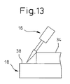
Fig. 13 shows a state in which the tool interferes with a reference surface of the workpiece; -
Fig. 14 is a flowchart showing an example of a procedure for adjusting the position and orientation of the tool at a teaching point; -
Fig. 15 shows a diagram indicating an image detection model of the workpiece; -
Fig. 16 shows an example in which the workpiece is actually detected by the vision sensor; -
Fig. 17a shows an example in which the height of the position of the tool is adjusted; -
Fig. 17b shows an example in which the orientation of the tool is adjusted; and -
Fig. 18 is a block diagram showing the robot program generating device according to the invention. - Concretely, a robot program generating device for processing according to the present invention may be a personal computer (hereinafter, referred to as a "PC") as schematically shown in
Fig. 1 . PC 10 has adisplay 12 capable indicating three-dimensional models of arobot 14, atool 16 attached torobot 14 for processing, aworkpiece 18 to be processed, a pedestal or ajig 20 forloading workpiece 18 thereon, and avision sensor 22 having a virtual camera forimaging workpiece 18 in PC 10.Display 12 of PC 10 can also indicate a graphic image of a three-dimensional model of workpiece 18 (in an illustrated embodiment, an image ofworkpiece 18 viewed from the above) captured byvirtual camera 22. In the illustrated embodiment,workpiece 18 has features, for example twoholes 26, for differentiating it from other workpieces.Workpiece 18 also has aprocessing line 28 or a site to be processed, which is used when the workpiece is processed (for example, burred) by usingtool 16. - A procedure carried out by PC 10 will be explained with reference to the flowchart shown in
Fig. 2 . First, in step S1, three-dimensional models of elements such asrobot 14 are indicated or located on the display so as to make a layout as shown inFig. 1 . Then, in step S2, aprocessing line 28 is assigned onworkpiece 18 which is used when the workpiece is actually processed bytool 16. - In the next step S3,
processing line 28 is divided into a plurality of line segments based on the shape of the processing line, as shown inFig. 3 . Concretely,processing line 28 is divided into segments each having a simple shape, such as a corner, a straight line and/or a curved line. In an example ofFig. 3 ,processing line 28 is divided into fourstraight line segments 28a and fourrounded corner segments 28b. - In the next step S4, in the layout as described above, a graphic image of
workpiece 18 viewed fromvirtual camera 22 is indicated on the display. Then, detection areas are determined in the graphic image viewed fromvirtual camera 22 such that each segment of the processing line generated in step S3 is included in the detection areas (step S5). At this point, since a teaching point included in the processing line is corrected in each divided segment as described below, it is preferable that there is a one-on-one relationship between each detection area and each segment. - In the next step S6, in order to actually detect the detection areas obtained in step S5 by using a vision sensor such as a camera, image detection models, each including each detection area, are generated in
graphic image 24 ofworkpiece 18 viewed fromvirtual camera 22, as shown inFig. 4 . As illustrated by using double-lined frames, the image detection models includes amodel 30 for detecting features orholes 26, and models 32a to 32h for detecting each detection area. - In the next step S7, in order to generate a program by which a robot can actually process a workpiece, a processing program, including data of teaching points for processing the segments of
processing line 28 ofworkpiece 18 as shown inFig. 5 , is generated. In an example ofFig. 5 , one teaching point is set to eachstraight line segment 28 and three teaching points are set to each corner segment. Then, a processing program, including a command line assigning the position of each teaching point and a processing speed at each teaching point, etc., is generated. The teaching points may be automatically set corresponding to the shape of each segment, otherwise, may be timely input by an operation such as a mouse click motion by an operator. - In the next step S8, a detection program is generated, by which a workpiece 18' to be processed is actually imaged or captured by a vision sensor such as a camera 22' corresponding to
virtual camera 22, in the similar positional relationship of the layout as generated in step S1, as shown inFig. 6 , and the position and orientation of each segment of workpiece 18' corresponding to each detection model generated in step S6 are detected. Further, a command line for calling the detection program is inserted into the above processing program.Fig. 6 shows an image obtained by the vision sensor and an example of a program into which the detection program (in the example, named as "VISION") is inserted. - In the next step S9, a command line, for calculating and obtaining an amount of change or a difference between the detection model and the actually captured image of the workpiece by the vision sensor, in relation to the position and the orientation of each segment, is generated and added to the processing program. There are two methods for calculating and obtaining the amount of change, i.e., a method for obtaining correction data as the amount of change of the position and orientation, by a command in a detection program for detecting the position and orientation of each segment of the workpiece; and another method for generating a calculation program (for example, named as "CALC") for calculating the position and orientation of each segment as shown in
Fig. 7 , and inserting a command calling the calculation program into the processing program. In an example ofFig. 7 , in aimage detection model 32h, the position or orientation of a processing line 28', included in a graphic image 24' of workpiece 18' actually captured by vision sensor 22', is different from the position or orientation of processingline 28 obtained by the virtual camera. In such a case, in the above calculation "CALC", the difference or the amount of change between thegraphic images 24' and 24, at each teaching point or some certain point on the processing line indetection model 32h. - Finally, in step S10, based on the amount of change calculated in step S9, a correction program is inserted into the processing program, the correction program being capable of correcting the teaching point for processing each segment such as a corner or a straight line. Due to this, an actual trajectory of the tool relative to the workpiece at each segment is corrected.
- According to the present invention, the amount of change of the position and orientation is calculated by comparing the image detection model of the three-dimensional model of the workpiece obtained by the virtual camera to the image of the workpiece actually captured by the vision sensor, and then the teaching point is corrected based on the amount of change. Therefore, even when the actual workpiece has a shape error, the shape error may be accommodated and the workpiece may be correctly processed along a desired processing line, whereby a processing accuracy of the workpiece may be significantly improved.
- In the above embodiment, the robot for carrying out processing and the vision sensor for capturing the workpiece are independently arranged. However, as in a preferred modification of
Fig. 8 , an imager such as acamera 22 may be attached to arobot 12 for processing aworkpiece 18, whereby the position of the camera may be adjusted. In this case, the processing program of the invention may further generate an imager movement program using the robot. Hereinafter, the procedure for generating the movement program will be explained with reference to a flowchart as shown inFig. 9 . - First, in step S21, a three-dimensional model of a workpiece is assigned in
PC 10. This assignment may be executed, for example, by mouse-clicking a workpiece to be assigned among workpieces indicated ondisplay 12. - In the next step S22, a
robot 14 is moved relative to a assignedworkpiece 18 such that avirtual camera 22 of a vision sensor attached to a front end of a hand of the robot is moved generally directly aboveworkpiece 18 and the orientation ofvirtual camera 22 is parallel to aprocessing surface 34 ofworkpiece 18, as shown infig. 10 . At this point, it is preferable that a calibration by whichcamera 22 may present the above position and orientation is executed based on an user coordinate system 36 (InFig. 10 , only X- and Z-axes are schematically indicated) including a X-Y plane parallel to processingsurface 34. - Then, a graphic image of the three-dimensional model of
workpiece 18 viewed fromvirtual camera 22 is indicated ondisplay 12 of PC 10 (step S23), and the horizontal position ofvirtual camera 22 is adjusted such thatprocessing surface 34 of the workpiece is positioned at the center of the image (step S24). Concretely, as shown inFig. 11 , a gap or displacement "d" between the center coordinate (for example, the center of gravity) ofprocessing surface 34 and the center of an image obtained by virtual camera 22 (for example, the center of a lens of the camera) is calculated, and then the position and orientation of the robot are determined such that the center coordinate ofprocessing surface 34 is positioned at the center of the graphic image of the three-dimensional model ofworkpiece 18 viewed fromvirtual camera 22. - In the next step S25, as shown in
Fig. 12 , the height of the position ofvirtual camera 22 is adjusted to a predetermined value "h" by operatingrobot 14. The height "h," defined as the distance from processingsurface 34 tovirtual camera 22, is predetermined such thatvirtual camera 22 can capture the whole ofworkpiece 18. The height "h" may be set by a user or operator, otherwise, may be determined based on a calculation or an experience. - After the position and orientation of
robot 14 by whichvirtual camera 22 can capture the whole ofworkpiece 18 are determined, an imager movement program for movingrobot 14 to the determined position and orientation is generated. Further, a teaching point is generated in relation to the determined position and orientation (step S26). - Finally, a command or a program for capturing and detecting a workpiece to be imaged by using an actual vision sensor such as a camera is generated (step S27), and then the command or the program is inserted into the imager movement program.
- Depending on the shape of a workpiece to be processed or a tool, it may be necessary to adjust the position and orientation of the tool at each teaching point. For example, in a case that workpiece 18 has a step portion as shown in
Fig. 13 , when processingsurface 34 or the upper surface of the step portion is to be processed by contactingtool 16 to processingsurface 34, the tool may interfere with areference surface 38 or the lower surface of the step portion, depending on the orientation of the tool. In such a case, it is necessary to modify the orientation oftool 16. Therefore, the modification of the position and/or orientation of the tool at the teaching point will be explained below, with reference to a flowchart as shown inFig. 14 . - First, in step S31, a
processing line 28 of aworkpiece 18 is assigned similarly in step S2 as described above, and then a processing program including data of a teaching point on processing line is generated. Similarly to the example ofFig. 5 , three teaching points are set to the corner segment and one teaching point is set to the straight line segment. Then, a processing program, including a command line assigning the position of each teaching point and a processing speed at each teaching point, etc., is generated. - In the next step S32, a graphic image of the three-dimensional model of
workpiece 18 viewed fromvirtual camera 22 is indicated ondisplay 12 ofPC 10. The positional relationship between the virtual camera and the workpiece may be the same as shown inFig. 1 . - In the next step S33, an image detection model having a reference surface and a processing surface of
workpiece 18 is generated, on agraphic image model 24 of the three-dimensional model of the workpiece viewed fromvirtual camera 22. Concretely, as illustrated inFig. 15 by using double-lined frames, the image detection models includes amodel 40 for detecting features or holes 26 ofgraphic image 24, amodel 42 for detecting aprocessing surface 34 of the workpiece, and amodel 44 for detecting areference surface 38 of the workpiece. The height of the position of processingsurface 34 relative to referencesurface 38 may be obtained by using the three-dimensional model of the workpiece. - In the next step S34, a command or a program is generated, by which a workpiece 18' to be processed is actually imaged or captured by a vision sensor such as a camera 22', as shown in
Fig. 16 , and the reference surface and the processing surface of workpiece 18' corresponding to each detection model generated in step S33 are detected from a captured image 24' obtained by camera 22'. Further, the generated command or the program thus generated is inserted into the processing program. - In the next step S35, a command or a program, for calculating the heights of the positions of the reference surface and the processing surface of the workpiece to be processed, is generated. Concretely, the difference of the sizes or the amount of change between an image of the workpiece actually capture by using vision sensor 22' (
Fig. 16 ) and the image detection model obtained by the virtual camera (Fig. 15 ) is calculated, in relation to each of the reference surface and the processing surface, and the size is converted into the height. - Finally, in step S36, the teaching point in the processing program is corrected based on the calculation result. In particular, as shown in
Fig. 17a , the height of the position of each teaching point in the processing program is corrected such thattool 16contacts processing surface 34 ofworkpiece 18, based on the calculated height of the position of the processing surface. Then, a clearance between a toolfront point 16a oftool 16 andreference surface 38 ofworkpiece 18 is calculated based on the height of the position of the reference surface. When the clearance is not sufficient or smaller than a predetermined threshold (e.g., as indicated inFig. 17a by a solid line), the tool may interfere with the reference surface in the actual processing. Therefore, as shown inFig. 17b , the orientation oftool 16 at each teaching point is corrected (step S37), in order to make a clearance, between the tool and the reference surface, which is equal to or larger than the predetermined threshold. - It should be understood by a person with ordinary skill in the art that the procedures as shown in
Figs. 2 ,9 and14 may be executed independently or in combination. - As described above, as shown in
Fig. 18 , program generating device 10 of the invention has a processing line assigning part 10a for assigning a processing line on the three-dimensional model of the workpiece on the display; a processing line dividing part 10b for dividing the processing line into a plurality of line segments; a detection area determining part 10c for determining a plurality of detection areas, each including each segment obtained by the processing line dividing part, within a graphic image obtained by capturing the three-dimensional model of the workpiece by using the three-dimensional model of the vision sensor as a virtual camera; a teaching point generating part 10d for generating a teaching point by which each segment of the processing line divided by processing line dividing part 10b is processed; a detection model generating part 10e for generating an image detection model in each detection area based on the graphic image, such that the vision sensor may detect each detection area of the graphic image determined by detection area determining part 10c; a detecting part 10f for reading an image obtained by actually capturing a workpiece to be processed by using a vision sensor, and detecting the position and the orientation of a portion of the workpiece corresponding to the image detection model; a change calculating part 10g for calculating an amount of change between the position and the orientation of each image detection model and the position and the orientation of each teaching point included in the detection area corresponding to the image detection model; and a correcting part 10h for correcting the position and the orientation of the teaching point included in the detection area corresponding to the image detection model, based on the amount of change. - Generating
device 10 may further comprise aprogram generating part 10i for generating an imager movement robot program wherein theprogram generating part 10i being capable of assigning the three-dimensional model of the workpiece so as to move the robot to a position where the vision sensor mounted to the robot can capture the workpiece to be processed; moving the robot to a position and orientation so that the orientation of the vision sensor is parallel to a surface of the three dimensional model to be processed; calculating the position and orientation of the robot in which the vision sensor captures the center of the three dimensional model of the workpiece, based on the positional relationship between the three dimensional models of the vision sensor and the workpiece; and generating a teaching point by which the vision sensor captures the whole of the three dimensional model of the workpiece. - Generating device may further comprise an
automatic adjusting part 10j for automatically adjusting the position and orientation of the teaching point by detecting the height of the surface of the workpiece to be processed from a reference surface of the workpiece by means of the vision sensor. - According to the generating device of the present invention, when the vision sensor is attached to the robot, the vision sensor attached to the robot may be used to generate a teaching point for capturing the workpiece, whereby man-hours required for the teaching operation may be significantly reduced.
- By detecting the height of the position of the processing surface of the workpiece from the reference surface and automatically correcting the position and orientation of the teaching point based on the detection result, interference between the workpiece and the tool for processing the workpiece may be avoided.
Claims (3)
- A generating device (10) of a processing robot program, by which three-dimensional models of a robot (14), a workpiece (18) and a vision sensor (22) are displayed on a display (12) and the robot (14) processes the workpiece (18), characterized in that the generating device comprises:a processing line assigning part (10a) for assigning a processing line (28) on the three-dimensional model of the workpiece (18) on the display (12);a processing line dividing part (10b) for dividing the processing line (28) into a plurality of line segments (28a, 28b);a detection area determining part (10c) for determining a plurality of detection areas, each including each segment (28a, 28b) obtained by the processing line dividing part (10b), within a graphic image obtained by capturing the three-dimensional model of the workpiece (18) by using the three-dimensional model of the vision sensor as a virtual camera (22);a teaching point generating part (10d) for generating a teaching point by which each segment (28a, 28b) of the processing line (28) divided by the processing line dividing part (10b) is processed;a detection model generating part (10e) for generating an image detection model in each detection area based on the graphic image, such that the vision sensor (22) may detect each detection area of the graphic image determined by the detection area determining part (10c);a detecting part (10f) for reading an image obtained by actually capturing a workpiece (18') to be processed by using a vision sensor (22'), and detecting the position and the orientation of a portion of the workpiece (18') corresponding to the image detection model;a change calculating part (10g) for calculating an amount of change between the position and the orientation of each image detection model and the position and the orientation of each teaching point included in the detection area corresponding to the image detection model; anda correcting part (10h) for correcting the position and the orientation of the teaching point included in the detection area corresponding to the image detection model, based on the amount of change.
- The generating device according to claim 1, characterized in that the generating device further comprises a program generating part (10i) for generating an imager movement robot program wherein the program generating part (10i) being capable of assigning the three-dimensional model of the workpiece (18) so as to move the robot (14) to a position where the vision sensor (22) mounted to the robot (14) can capture the workpiece (18) to be processed; moving the robot (14) to a position and orientation so that the orientation of the vision sensor (22) is parallel to a surface (34) of the three dimensional model to be processed; calculating the position and orientation of the robot (14) in which the vision sensor (22) captures the center of the three dimensional model of the workpiece (18), based on the positional relationship between the three dimensional models of the vision sensor (22) and the workpiece (18); and generating a teaching point by which the vision sensor (22) captures the whole of the three dimensional model of the workpiece (18).
- The generating device according to claim 1, characterized in that the generating device further comprises an automatic adjusting part (10j) for automatically adjusting the position and orientation of the teaching point by detecting the height of the surface (34) of the workpiece to be processed from a reference surface (38) of the workpiece (18) by means of the vision sensor (22).
Applications Claiming Priority (1)
| Application Number | Priority Date | Filing Date | Title |
|---|---|---|---|
| JP2008012736A JP4347386B2 (en) | 2008-01-23 | 2008-01-23 | Processing robot program creation device |
Publications (3)
| Publication Number | Publication Date |
|---|---|
| EP2082850A2 true EP2082850A2 (en) | 2009-07-29 |
| EP2082850A3 EP2082850A3 (en) | 2010-01-20 |
| EP2082850B1 EP2082850B1 (en) | 2011-05-25 |
Family
ID=40210460
Family Applications (1)
| Application Number | Title | Priority Date | Filing Date |
|---|---|---|---|
| EP08020097A Active EP2082850B1 (en) | 2008-01-23 | 2008-11-18 | Generating device of processing robot program |
Country Status (4)
| Country | Link |
|---|---|
| US (1) | US20090187276A1 (en) |
| EP (1) | EP2082850B1 (en) |
| JP (1) | JP4347386B2 (en) |
| CN (1) | CN101493682B (en) |
Cited By (7)
| Publication number | Priority date | Publication date | Assignee | Title |
|---|---|---|---|---|
| EP2369434A1 (en) * | 2010-03-26 | 2011-09-28 | Richard Meyer-Theilinger | Method for automatic removal of a material volume |
| EP2420360A1 (en) * | 2010-08-18 | 2012-02-22 | KUKA Roboter GmbH | Method and programming means for programming a robot |
| CN103085067A (en) * | 2011-11-08 | 2013-05-08 | 发那科株式会社 | Robot programming device |
| WO2014008949A1 (en) * | 2012-07-13 | 2014-01-16 | Abb Technology Ltd | A method for programming an industrial robot in a virtual environment |
| DE102014108956B4 (en) * | 2013-06-28 | 2016-12-15 | Fanuc Corporation | Device for deburring with visual sensor and force sensor |
| WO2019110270A1 (en) * | 2017-12-06 | 2019-06-13 | Kuka Deutschland Gmbh | Method and system for component processing by robot |
| US20230219223A1 (en) * | 2020-06-05 | 2023-07-13 | Fanuc Corporation | Programming device |
Families Citing this family (37)
| Publication number | Priority date | Publication date | Assignee | Title |
|---|---|---|---|---|
| JP2010131711A (en) * | 2008-12-05 | 2010-06-17 | Honda Motor Co Ltd | Method of controlling robot arm |
| JP5428639B2 (en) * | 2009-08-19 | 2014-02-26 | 株式会社デンソーウェーブ | Robot control apparatus and robot teaching method |
| US20110070342A1 (en) * | 2009-08-26 | 2011-03-24 | Wilkens Patrick J | Method for evaluating and orientating baked product |
| JP5324397B2 (en) * | 2009-11-02 | 2013-10-23 | 本田技研工業株式会社 | Information processing method, apparatus and program |
| CN102359783B (en) * | 2011-07-22 | 2013-08-07 | 北京大学 | Vision-based mobile robot positioning method |
| CN103827763A (en) * | 2011-09-28 | 2014-05-28 | 株式会社安川电机 | Robot system and workpiece production method |
| EP2590040B1 (en) * | 2011-11-04 | 2014-05-28 | Nivora IP B.V. | Method and device for aiding in manual handling of a work piece during machining |
| JP2013167481A (en) * | 2012-02-14 | 2013-08-29 | Olympus Corp | Image processor and program |
| JP2014102685A (en) * | 2012-11-20 | 2014-06-05 | Sony Corp | Information processing apparatus, information processing method, and program |
| JP5670416B2 (en) * | 2012-12-28 | 2015-02-18 | ファナック株式会社 | Robot system display device |
| JP2014222393A (en) * | 2013-05-13 | 2014-11-27 | キヤノン株式会社 | Moving body arrangement determination method, measuring apparatus, processing device, and program |
| JP6005299B2 (en) * | 2013-11-28 | 2016-10-12 | 三菱電機株式会社 | Robot system and control method of robot system |
| JP5815761B2 (en) * | 2014-01-23 | 2015-11-17 | ファナック株式会社 | Visual sensor data creation system and detection simulation system |
| JP5850958B2 (en) * | 2014-01-24 | 2016-02-03 | ファナック株式会社 | Robot programming device for creating a robot program for imaging a workpiece |
| JP5850962B2 (en) * | 2014-02-13 | 2016-02-03 | ファナック株式会社 | Robot system using visual feedback |
| CN106103012B (en) * | 2014-03-27 | 2017-12-12 | 松下知识产权经营株式会社 | robot control method |
| US9737990B2 (en) | 2014-05-16 | 2017-08-22 | Microsoft Technology Licensing, Llc | Program synthesis for robotic tasks |
| JP5927310B1 (en) * | 2015-01-14 | 2016-06-01 | ファナック株式会社 | Robot system simulation device |
| JP6294248B2 (en) | 2015-01-28 | 2018-03-14 | ファナック株式会社 | Scraping processing apparatus and scraping processing method using a robot |
| JP6062973B2 (en) * | 2015-01-30 | 2017-01-18 | ファナック株式会社 | Numerical control device capable of searching for nearby points in consideration of tool posture |
| CN105425721A (en) * | 2015-11-10 | 2016-03-23 | 佛山市新恒萃材料科技有限公司 | Intelligent teaching method of closed-loop control and device thereof |
| DE102015119806A1 (en) * | 2015-11-16 | 2017-05-18 | Grob-Werke Gmbh & Co. Kg | Method for displaying machining in a machine tool |
| WO2018072134A1 (en) * | 2016-10-19 | 2018-04-26 | Abb Schweiz Ag | Robot processing path automatic compensation method |
| JP6571723B2 (en) | 2017-07-11 | 2019-09-04 | ファナック株式会社 | PROGRAMMING DEVICE FOR GENERATING OPERATION PROGRAM AND PROGRAM GENERATION METHOD |
| TWI650626B (en) * | 2017-08-15 | 2019-02-11 | 由田新技股份有限公司 | Robot processing method and system based on 3d image |
| JP6795471B2 (en) * | 2017-08-25 | 2020-12-02 | ファナック株式会社 | Robot system |
| TWI672207B (en) | 2017-11-03 | 2019-09-21 | 財團法人工業技術研究院 | Posture positioning system for machine and the method thereof |
| JP6878391B2 (en) * | 2018-12-18 | 2021-05-26 | ファナック株式会社 | Robot system and its adjustment method |
| JP7376268B2 (en) * | 2019-07-22 | 2023-11-08 | ファナック株式会社 | 3D data generation device and robot control system |
| CN114080304B (en) * | 2019-08-22 | 2024-05-14 | 欧姆龙株式会社 | Control device, control method, and control program |
| JP7362453B2 (en) * | 2019-11-28 | 2023-10-17 | 株式会社日立製作所 | Model creation device and model creation method |
| CN112947307A (en) * | 2021-01-22 | 2021-06-11 | 青岛黄海学院 | Control method for surface appearance of high-speed cutting workpiece |
| TW202234184A (en) * | 2021-02-25 | 2022-09-01 | 日商發那科股份有限公司 | A simulation device using 3D position information obtained from the output of a vision sensor |
| JP2022159211A (en) * | 2021-03-31 | 2022-10-17 | 株式会社アットロボティクス | Tool floating mechanism, machining device, and machining device tool floating mechanism |
| CN117203590A (en) | 2021-05-31 | 2023-12-08 | 发那科株式会社 | programming device |
| CN118414587A (en) * | 2022-03-07 | 2024-07-30 | 发那科株式会社 | Device for generating search program of robot |
| JP7762613B2 (en) * | 2022-03-29 | 2025-10-30 | 大同マシナリー株式会社 | processing equipment |
Citations (3)
| Publication number | Priority date | Publication date | Assignee | Title |
|---|---|---|---|---|
| JPH0531659A (en) | 1991-07-26 | 1993-02-09 | Hitachi Ltd | Deburring method and device |
| JPH05233048A (en) | 1992-02-21 | 1993-09-10 | Hitachi Ltd | Deburring / polishing route teaching data generation method, deburring / polishing robot control method, and deburring / polishing robot system |
| JP2008012736A (en) | 2006-07-04 | 2008-01-24 | Dainippon Printing Co Ltd | Multicolor printing registration adjustment information presentation apparatus and method |
Family Cites Families (54)
| Publication number | Priority date | Publication date | Assignee | Title |
|---|---|---|---|---|
| JPS63196388A (en) * | 1987-02-06 | 1988-08-15 | 株式会社東芝 | Teaching device for remote control robot |
| JP2708458B2 (en) * | 1988-04-01 | 1998-02-04 | 株式会社豊田中央研究所 | Copy control robot |
| JPH041505A (en) * | 1990-04-18 | 1992-01-07 | Matsushita Electric Ind Co Ltd | 3D position measurement method of workpiece and workpiece capture method |
| JPH05165509A (en) * | 1991-12-12 | 1993-07-02 | Hitachi Ltd | Deburring robot path generation method |
| JPH07210687A (en) * | 1994-01-18 | 1995-08-11 | Matsushita Electric Ind Co Ltd | Shape detector |
| US5552575A (en) * | 1994-07-15 | 1996-09-03 | Tufts University | Scan welding method and apparatus |
| JP3376179B2 (en) * | 1995-08-03 | 2003-02-10 | キヤノン株式会社 | Surface position detection method |
| JP3687980B2 (en) * | 1996-11-07 | 2005-08-24 | 株式会社ミツトヨ | Measurement program creation in NC machining and machining management that executed this measurement program |
| JP3269005B2 (en) * | 1997-05-12 | 2002-03-25 | 川崎重工業株式会社 | Robot controller |
| JP3655083B2 (en) * | 1998-02-25 | 2005-06-02 | 富士通株式会社 | Interface device for positioning the robot |
| JP3951079B2 (en) * | 1998-09-14 | 2007-08-01 | 株式会社安川電機 | OFFLINE TEACHING METHOD, OFFLINE TEACHING DEVICE, AND RECORDING MEDIUM |
| WO2000037884A1 (en) * | 1998-12-22 | 2000-06-29 | Mitsubishi Denki Kabushiki Kaisha | Method and apparatus for measuring positioning error using index mark, and machining apparatus that corrects error based on measured result |
| US7092860B1 (en) * | 1999-02-03 | 2006-08-15 | Mitutoyo Corporation | Hardware simulation systems and methods for vision inspection systems |
| US6748104B1 (en) * | 2000-03-24 | 2004-06-08 | Cognex Corporation | Methods and apparatus for machine vision inspection using single and multiple templates or patterns |
| US20020133264A1 (en) * | 2001-01-26 | 2002-09-19 | New Jersey Institute Of Technology | Virtual reality system for creation of design models and generation of numerically controlled machining trajectories |
| JP3715537B2 (en) * | 2001-02-19 | 2005-11-09 | 本田技研工業株式会社 | Interference avoidance method and program for articulated robot |
| JP4739556B2 (en) * | 2001-03-27 | 2011-08-03 | 株式会社安川電機 | Remote adjustment and abnormality judgment device for control target |
| DE10144932B4 (en) * | 2001-09-12 | 2014-07-31 | Siemens Aktiengesellschaft | Visualization of workpieces in the simulation of milling processes |
| JP2003108609A (en) * | 2001-09-26 | 2003-04-11 | Mazda Motor Corp | Morphing method of structure shape, computer program thereof, and computer-readable storage medium |
| GB0125079D0 (en) * | 2001-10-18 | 2001-12-12 | Cimac Automation Ltd | Auto motion:robot guidance for manufacturing |
| JP2003150219A (en) * | 2001-11-12 | 2003-05-23 | Fanuc Ltd | Simulation device for work machine |
| JP3806342B2 (en) * | 2001-11-26 | 2006-08-09 | 三菱重工業株式会社 | Three-dimensional object welding method and apparatus |
| US6587752B1 (en) * | 2001-12-25 | 2003-07-01 | National Institute Of Advanced Industrial Science And Technology | Robot operation teaching method and apparatus |
| GB0130986D0 (en) * | 2001-12-27 | 2002-02-13 | Prophet Control Systems Ltd | Programming robots with offline design |
| CA2369845A1 (en) * | 2002-01-31 | 2003-07-31 | Braintech, Inc. | Method and apparatus for single camera 3d vision guided robotics |
| EP1472052A2 (en) * | 2002-01-31 | 2004-11-03 | Braintech Canada, Inc. | Method and apparatus for single camera 3d vision guided robotics |
| US7024272B2 (en) * | 2002-04-26 | 2006-04-04 | Delphi Technologies, Inc. | Virtual design, inspect and grind optimization process |
| SE524818C2 (en) * | 2003-02-13 | 2004-10-05 | Abb Ab | A method and system for programming an industrial robot to move relatively defined positions on an object |
| JP3708083B2 (en) * | 2003-02-28 | 2005-10-19 | ファナック株式会社 | Robot teaching device |
| JP2004294551A (en) * | 2003-03-25 | 2004-10-21 | Toshiba Corp | Optical proximity correction method, optical proximity correction apparatus, and program |
| JP2004299013A (en) * | 2003-03-31 | 2004-10-28 | Fanuc Ltd | Robot off-line programming device having error correction feed-back function |
| JP3797986B2 (en) * | 2003-07-03 | 2006-07-19 | ファナック株式会社 | Robot offline simulation equipment |
| JP3819883B2 (en) * | 2003-08-27 | 2006-09-13 | ファナック株式会社 | Robot program position correction device |
| DE10345743A1 (en) * | 2003-10-01 | 2005-05-04 | Kuka Roboter Gmbh | Method and device for determining the position and orientation of an image receiving device |
| JP2005108144A (en) * | 2003-10-02 | 2005-04-21 | Fanuc Ltd | Device for confirming correction data of robot |
| JP3732494B2 (en) * | 2003-10-31 | 2006-01-05 | ファナック株式会社 | Simulation device |
| US20070282480A1 (en) * | 2003-11-10 | 2007-12-06 | Pannese Patrick D | Methods and systems for controlling a semiconductor fabrication process |
| JP4098761B2 (en) * | 2004-08-17 | 2008-06-11 | ファナック株式会社 | Finishing method |
| US7857021B2 (en) * | 2004-09-09 | 2010-12-28 | Usnr/Kockums Cancar Company | System for positioning a workpiece |
| JP2006099260A (en) * | 2004-09-28 | 2006-04-13 | Fanuc Ltd | Robot program creating device |
| JP4087841B2 (en) * | 2004-12-21 | 2008-05-21 | ファナック株式会社 | Robot controller |
| US7643907B2 (en) * | 2005-02-10 | 2010-01-05 | Abb Research Ltd. | Method and apparatus for developing a metadata-infused software program for controlling a robot |
| JP4262690B2 (en) * | 2005-03-16 | 2009-05-13 | 株式会社日立ハイテクノロジーズ | Shape measuring apparatus and shape measuring method |
| JP4266946B2 (en) * | 2005-03-17 | 2009-05-27 | ファナック株式会社 | Offline teaching device |
| JP2006285899A (en) * | 2005-04-05 | 2006-10-19 | Sony Corp | Learning device and learning method, generating device and generating method, and program |
| JP2006289531A (en) * | 2005-04-07 | 2006-10-26 | Seiko Epson Corp | Movement control device for robot position teaching, robot position teaching device, movement control method for robot position teaching, robot position teaching method, and movement control program for robot position teaching |
| JP4737668B2 (en) * | 2005-05-30 | 2011-08-03 | コニカミノルタセンシング株式会社 | 3D measurement method and 3D measurement system |
| JP3971773B2 (en) * | 2005-10-12 | 2007-09-05 | ファナック株式会社 | Offline teaching device for robots |
| JP4153528B2 (en) * | 2006-03-10 | 2008-09-24 | ファナック株式会社 | Apparatus, program, recording medium and method for robot simulation |
| JP4238256B2 (en) * | 2006-06-06 | 2009-03-18 | ファナック株式会社 | Robot simulation device |
| JP4235214B2 (en) * | 2006-07-04 | 2009-03-11 | ファナック株式会社 | Apparatus, program, recording medium, and method for creating robot program |
| JP4271232B2 (en) * | 2006-12-20 | 2009-06-03 | ファナック株式会社 | Apparatus, method, program, and recording medium for executing offline programming of robot |
| US8053279B2 (en) * | 2007-06-19 | 2011-11-08 | Micron Technology, Inc. | Methods and systems for imaging and cutting semiconductor wafers and other semiconductor workpieces |
| JP5236507B2 (en) * | 2009-01-07 | 2013-07-17 | 本田技研工業株式会社 | Seam welding method and seam welding apparatus |
-
2008
- 2008-01-23 JP JP2008012736A patent/JP4347386B2/en active Active
- 2008-11-18 EP EP08020097A patent/EP2082850B1/en active Active
- 2008-11-19 US US12/273,730 patent/US20090187276A1/en not_active Abandoned
- 2008-12-18 CN CN2008101860071A patent/CN101493682B/en active Active
Patent Citations (3)
| Publication number | Priority date | Publication date | Assignee | Title |
|---|---|---|---|---|
| JPH0531659A (en) | 1991-07-26 | 1993-02-09 | Hitachi Ltd | Deburring method and device |
| JPH05233048A (en) | 1992-02-21 | 1993-09-10 | Hitachi Ltd | Deburring / polishing route teaching data generation method, deburring / polishing robot control method, and deburring / polishing robot system |
| JP2008012736A (en) | 2006-07-04 | 2008-01-24 | Dainippon Printing Co Ltd | Multicolor printing registration adjustment information presentation apparatus and method |
Cited By (10)
| Publication number | Priority date | Publication date | Assignee | Title |
|---|---|---|---|---|
| EP2369434A1 (en) * | 2010-03-26 | 2011-09-28 | Richard Meyer-Theilinger | Method for automatic removal of a material volume |
| EP2420360A1 (en) * | 2010-08-18 | 2012-02-22 | KUKA Roboter GmbH | Method and programming means for programming a robot |
| CN103085067A (en) * | 2011-11-08 | 2013-05-08 | 发那科株式会社 | Robot programming device |
| CN103085067B (en) * | 2011-11-08 | 2016-04-20 | 发那科株式会社 | Mechanical hand-knitted range device |
| WO2014008949A1 (en) * | 2012-07-13 | 2014-01-16 | Abb Technology Ltd | A method for programming an industrial robot in a virtual environment |
| DE102014108956B4 (en) * | 2013-06-28 | 2016-12-15 | Fanuc Corporation | Device for deburring with visual sensor and force sensor |
| US9724801B2 (en) | 2013-06-28 | 2017-08-08 | Fanuc Corporation | Deburring device including visual sensor and force sensor |
| WO2019110270A1 (en) * | 2017-12-06 | 2019-06-13 | Kuka Deutschland Gmbh | Method and system for component processing by robot |
| US20230219223A1 (en) * | 2020-06-05 | 2023-07-13 | Fanuc Corporation | Programming device |
| US12358134B2 (en) * | 2020-06-05 | 2025-07-15 | Fanuc Corporation | Programming device |
Also Published As
| Publication number | Publication date |
|---|---|
| EP2082850A3 (en) | 2010-01-20 |
| US20090187276A1 (en) | 2009-07-23 |
| JP4347386B2 (en) | 2009-10-21 |
| CN101493682B (en) | 2011-04-27 |
| EP2082850B1 (en) | 2011-05-25 |
| CN101493682A (en) | 2009-07-29 |
| JP2009175954A (en) | 2009-08-06 |
Similar Documents
| Publication | Publication Date | Title |
|---|---|---|
| EP2082850B1 (en) | Generating device of processing robot program | |
| CN112276936B (en) | Three-dimensional data generating device and robot control system | |
| JP3732494B2 (en) | Simulation device | |
| CN109940605B (en) | Compliant assembly system and method integrating three-dimensional vision and contact force analysis | |
| JP3596753B2 (en) | Apparatus and method for generating part program for image measuring device | |
| JP4021413B2 (en) | Measuring device | |
| TWI670153B (en) | Robot and robot system | |
| CN118314138B (en) | Laser processing method and system based on machine vision | |
| EP3910593A1 (en) | Image processing device, work robot, substrate inspection device, and specimen inspection device | |
| JP4171488B2 (en) | Offline programming device | |
| US20240351205A1 (en) | Command value generating device, method, and program | |
| JP6129058B2 (en) | Teaching point correction apparatus and teaching point correction method | |
| JP6885856B2 (en) | Robot system and calibration method | |
| KR20130075712A (en) | Laser vision sensor and its correction method | |
| CN104802186A (en) | Robot programming apparatus for creating robot program for capturing image of workpiece | |
| JP7414850B2 (en) | robot system | |
| CN116867619B (en) | Teaching device | |
| CN115697628B (en) | Image processing device and machine tool | |
| CN112643718B (en) | Image processing apparatus, control method therefor, and storage medium storing control program therefor | |
| JP7533265B2 (en) | Support system, image processing device, support method and program | |
| US12420424B2 (en) | Coordinate system setting system and position/orientation measurement system | |
| JP7483455B2 (en) | Image processing device, method and program for controlling the image processing device | |
| JP2012236266A (en) | Robot control system, robot system, and program | |
| JP2007071835A (en) | Part program generating apparatus for image measuring apparatus, part program generating method for image measuring apparatus, and part program generating program for image measuring apparatus | |
| JP2007026423A (en) | Image processing apparatus and image processing method |
Legal Events
| Date | Code | Title | Description |
|---|---|---|---|
| PUAI | Public reference made under article 153(3) epc to a published international application that has entered the european phase |
Free format text: ORIGINAL CODE: 0009012 |
|
| AK | Designated contracting states |
Kind code of ref document: A2 Designated state(s): AT BE BG CH CY CZ DE DK EE ES FI FR GB GR HR HU IE IS IT LI LT LU LV MC MT NL NO PL PT RO SE SI SK TR |
|
| AX | Request for extension of the european patent |
Extension state: AL BA MK RS |
|
| PUAL | Search report despatched |
Free format text: ORIGINAL CODE: 0009013 |
|
| AK | Designated contracting states |
Kind code of ref document: A3 Designated state(s): AT BE BG CH CY CZ DE DK EE ES FI FR GB GR HR HU IE IS IT LI LT LU LV MC MT NL NO PL PT RO SE SI SK TR |
|
| AX | Request for extension of the european patent |
Extension state: AL BA MK RS |
|
| RIC1 | Information provided on ipc code assigned before grant |
Ipc: G05B 19/408 20060101ALI20091214BHEP Ipc: B25J 9/16 20060101AFI20090114BHEP |
|
| 17P | Request for examination filed |
Effective date: 20100202 |
|
| 17Q | First examination report despatched |
Effective date: 20100308 |
|
| AKX | Designation fees paid |
Designated state(s): DE |
|
| RIC1 | Information provided on ipc code assigned before grant |
Ipc: G05B 19/408 20060101ALI20100903BHEP Ipc: B25J 9/16 20060101AFI20100903BHEP |
|
| GRAP | Despatch of communication of intention to grant a patent |
Free format text: ORIGINAL CODE: EPIDOSNIGR1 |
|
| RAP1 | Party data changed (applicant data changed or rights of an application transferred) |
Owner name: FANUC CORPORATION |
|
| GRAS | Grant fee paid |
Free format text: ORIGINAL CODE: EPIDOSNIGR3 |
|
| GRAA | (expected) grant |
Free format text: ORIGINAL CODE: 0009210 |
|
| AK | Designated contracting states |
Kind code of ref document: B1 Designated state(s): DE |
|
| REG | Reference to a national code |
Ref country code: DE Ref legal event code: R096 Ref document number: 602008007167 Country of ref document: DE Effective date: 20110707 |
|
| PLBE | No opposition filed within time limit |
Free format text: ORIGINAL CODE: 0009261 |
|
| STAA | Information on the status of an ep patent application or granted ep patent |
Free format text: STATUS: NO OPPOSITION FILED WITHIN TIME LIMIT |
|
| 26N | No opposition filed |
Effective date: 20120228 |
|
| REG | Reference to a national code |
Ref country code: DE Ref legal event code: R097 Ref document number: 602008007167 Country of ref document: DE Effective date: 20120228 |
|
| PGFP | Annual fee paid to national office [announced via postgrant information from national office to epo] |
Ref country code: DE Payment date: 20251022 Year of fee payment: 18 |