EP2082820A2 - Chipping tool - Google Patents
Chipping tool Download PDFInfo
- Publication number
- EP2082820A2 EP2082820A2 EP09000900A EP09000900A EP2082820A2 EP 2082820 A2 EP2082820 A2 EP 2082820A2 EP 09000900 A EP09000900 A EP 09000900A EP 09000900 A EP09000900 A EP 09000900A EP 2082820 A2 EP2082820 A2 EP 2082820A2
- Authority
- EP
- European Patent Office
- Prior art keywords
- recess
- cutting
- holder
- cutting plate
- cutting tool
- Prior art date
- Legal status (The legal status is an assumption and is not a legal conclusion. Google has not performed a legal analysis and makes no representation as to the accuracy of the status listed.)
- Withdrawn
Links
Images


Classifications
-
- B—PERFORMING OPERATIONS; TRANSPORTING
- B23—MACHINE TOOLS; METAL-WORKING NOT OTHERWISE PROVIDED FOR
- B23B—TURNING; BORING
- B23B27/00—Tools for turning or boring machines; Tools of a similar kind in general; Accessories therefor
- B23B27/04—Cutting-off tools
- B23B27/045—Cutting-off tools with chip-breaking arrangements
-
- B—PERFORMING OPERATIONS; TRANSPORTING
- B23—MACHINE TOOLS; METAL-WORKING NOT OTHERWISE PROVIDED FOR
- B23B—TURNING; BORING
- B23B27/00—Tools for turning or boring machines; Tools of a similar kind in general; Accessories therefor
- B23B27/08—Cutting tools with blade- or disc-like main parts
- B23B27/083—Cutting tools with disc-like main parts
-
- B—PERFORMING OPERATIONS; TRANSPORTING
- B23—MACHINE TOOLS; METAL-WORKING NOT OTHERWISE PROVIDED FOR
- B23B—TURNING; BORING
- B23B29/00—Holders for non-rotary cutting tools; Boring bars or boring heads; Accessories for tool holders
- B23B29/04—Tool holders for a single cutting tool
- B23B29/043—Tool holders for a single cutting tool with cutting-off, grooving or profile cutting tools, i.e. blade- or disc-like main cutting parts
-
- B—PERFORMING OPERATIONS; TRANSPORTING
- B23—MACHINE TOOLS; METAL-WORKING NOT OTHERWISE PROVIDED FOR
- B23B—TURNING; BORING
- B23B2200/00—Details of cutting inserts
- B23B2200/08—Rake or top surfaces
- B23B2200/086—Rake or top surfaces with one or more grooves
- B23B2200/088—Rake or top surfaces with one or more grooves for clamping
-
- B—PERFORMING OPERATIONS; TRANSPORTING
- B23—MACHINE TOOLS; METAL-WORKING NOT OTHERWISE PROVIDED FOR
- B23B—TURNING; BORING
- B23B2200/00—Details of cutting inserts
- B23B2200/16—Supporting or bottom surfaces
- B23B2200/167—Supporting or bottom surfaces with serrations
-
- B—PERFORMING OPERATIONS; TRANSPORTING
- B23—MACHINE TOOLS; METAL-WORKING NOT OTHERWISE PROVIDED FOR
- B23B—TURNING; BORING
- B23B2260/00—Details of constructional elements
- B23B2260/004—Adjustable elements
-
- B—PERFORMING OPERATIONS; TRANSPORTING
- B23—MACHINE TOOLS; METAL-WORKING NOT OTHERWISE PROVIDED FOR
- B23B—TURNING; BORING
- B23B2260/00—Details of constructional elements
- B23B2260/124—Screws
Definitions
- the two contact surfaces have an angle of 1 ° - 4 ° to each other.
- the thickness of the web is 0.75 to 1.5 times the height of the slot.
- the ratio between the height of the slot and the length of the slot 1: 2 to 1: 4 especially if the slot is a height from 1.5 to 3.0 mm and a length of 5 to 8 mm.
- the slot in particular its length adapted to the length of the cutting plate, on the one hand a sufficient elasticity of the remaining between the slot and the recess web is achieved so that it yields elastically upon insertion of the cutting plate into the recess and when the cutting plate completely in the recess is inserted, holding the same with a very high force.
- restricting the length of the slot prevents excessive weakening of the insert holder so that it remains stable even with high cutting forces received by the insert holder and keeps the insert in the desired position, thus ensuring precise and uniform cutting is possible.
- the cutting tool according to the invention can therefore absorb higher cutting forces.
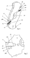
- the second edge portion 13b is disposed on an upper surface of the portion 12 and will therefore be referred to as an upper edge portion 13b hereinafter, whereas the third edge portion 13c is disposed on an underside of the portion 12 and therefore referred to as a lower edge portion 13c.
- the elevations 16 and the recesses 17 of the teeth 15 are each rounded and thus form a wave-shaped profile of the teeth 15.
- the teeth 18 of the cutting plate holder 3 in which case the elevations 16 are flattened.
- the rounded shape can be made particularly simple.
- the number of elevations 16 and depressions 17 of the teeth 15 and 18 depends in particular on the width of the cutting plate 6 and can therefore be different from the illustrated number.
- the insert holder 3 has a recess 5 spaced from the closed slot 22, which is arranged on that side of the recess 5, at the intended use of the cutting tool 1, the highest cutting force occurs.
- the cutting plate 6 in the illustration according to Fig. 7 indicated only by a dashed line, the skilled person is, however, readily understood that this is the side of the cutting edge 11 of the cutting plate 6 opposite.
- Fig. 7 in synopsis with Fig. 1 It is clear that the slot 22 at the opening 5a of the recess 5 opposite side, ie on the side at which the recess 5 is closed, does not extend beyond the longitudinal extension of the cutting plate 6 addition. As a result, an excessive weakening of the insert holder 3 is prevented, so that it remains stable even at high cutting forces.
- Fig. 9 shown in an enlarged sectional view adjusting device 26 has located on the cutting plate holder 3 inclined surface 27 and a screwed into the base holder 4 screw 28 having a corresponding with the inclined surface 27 of the insert holder 3 inclined surface 29.
- the insert holder 3 has not only two recesses 5, but also two inclined surfaces 27.
- the two inclined surfaces 27 and 29 are arranged relative to each other such that a rotation the adjusting screw 28 causes a rotation of the insert holder 3, since the adjusting screw slides in its rotation on the inclined surface 27 of the insert holder 3 along and thereby moves.
- a rotation of the cutting plate holder 3 in turn leads to an adjustment of the height or position of the arranged in the recess 5 of the cutting plate holder 3 cutting plate 6.
- the cutting plate 6 can be adjusted relative to the peak height of the workpiece 2.
- the inclined surfaces 27 and 29 of the adjusting screw 28 and the cutting plate holder 3 are formed in the present case each as a lateral surfaces of a truncated cone and preferably have an angle of about 45 °.
- a plurality, in particular two, parallel to each other arranged cutting plate holder 4 are mounted with corresponding inserts 6 on the base holder 4.
- a corresponding number of cuts can be introduced simultaneously into the workpiece 2.
- the central fixing screw 10 may extend through both insert holders 3 and the base holder 4 and be connected to a nut formed in a suitable manner.
Abstract
Description
Die Erfindung betrifft ein Zerspanungswerkzeug mit wenigstens einer Schneidplatte und mit wenigstens einem Schneidplattenhalter nach der im Oberbegriff von Anspruch 1 näher definierten Art.The invention relates to a cutting tool with at least one cutting plate and at least one insert holder according to the closer defined in the preamble of
Des weiteren betrifft die Erfindung ein Zerspanungswerkzeug mit einem Grundhalter, an dem wenigstens ein Schneidplattenhalter angebracht ist, welcher wenigstens eine Ausnehmung zur Aufnahme einer Schneidplatte aufweist, nach der im Oberbegriff von Anspruch 9 näher definierten Art.Furthermore, the invention relates to a cutting tool with a base holder on which at least one cutting plate holder is mounted, which has at least one recess for receiving a cutting plate, according to the closer defined in the preamble of
Ein gattungsgemäßes Zerspanungswerkzeug ist aus der
Aus der
Die
Ein weiteres Zerspanungswerkzeug mit einer eine Verzahnung aufweisenden Ausnehmung zur Aufnahme der Schneidplatte ist in der
Keine dieser Lösungen ermöglicht jedoch einen auch bei hohen Schnittkräften sicheren Halt der Schneidplatte innerhalb der Ausnehmung.However, none of these solutions enables a secure hold of the cutting plate within the recess, even at high cutting forces.
Ein Zerspanungswerkzeug gemäß dem Oberbegriff von Anspruch 9 ist aus der
Die
Ein weiteres Zerspanungswerkzeug ist in der
Es ist Aufgabe der vorliegenden Erfindung, ein Zerspanungswerkzeug mit einem Schneidplattenhalter und einer durch denselben gehaltenen Schneidplatte zu schaffen, welches einerseits einen sicheren Halt der Schneidplatte innerhalb der Ausnehmung des Schneidplattenhalters gewährleistet, welches andererseits jedoch auch bei hohen Schnittkräften nicht zum Brechen neigt.It is an object of the present invention to provide a cutting tool with a cutting plate holder and a cutting plate held by the same, which on the one hand ensures a secure hold of the cutting plate within the recess of the cutting plate holder, on the other hand, however, does not tend to break even at high cutting forces.
Erfindungsgemäß wird diese Aufgabe durch die in Anspruch 1 genannten Merkmale gelöst.According to the invention, this object is achieved by the features mentioned in
Durch die erfindungsgemäße Ausführung des Schlitzes, insbesondere dessen an die Länge der Schneidplatte angepasste Länge, wird einerseits eine ausreichende Elastizität des zwischen dem Schlitz und der Ausnehmung verbleibenden Stegs erreicht, so dass dieser beim Einführen der Schneidplatte in die Ausnehmung elastisch nachgibt und wenn die Schneidplatte vollständig in die Ausnehmung eingesetzt ist, dieselbe mit einer sehr hohen Kraft festhält. Andererseits wird durch die Beschränkung der Länge des Schlitzes eine zu starke Schwächung des Schneidplattenhalters verhindert, so dass dieser auch bei hohen Schnittkräften, die durch den Schneidplattenhalter aufgenommen werden, stabil bleibt und die Schneidplatte in der gewünschten Position hält, so dass eine präzise und gleichmäßige Zerspanung möglich ist. Gegenüber der bekannten Lösung kann das erfindungsgemäße Zerspanungswerkzeug also höhere Schnittkräfte aufnehmen.Due to the inventive design of the slot, in particular adapted to the length of the cutting plate Length, on the one hand sufficient elasticity of the remaining between the slot and the recess web is achieved so that it yields elastically upon insertion of the cutting plate into the recess and when the cutting plate is fully inserted into the recess, the same holds with a very high force. On the other hand, restricting the length of the slot prevents excessive weakening of the insert holder so that it remains stable even with high cutting forces received by the insert holder and keeps the insert in the desired position, thus ensuring precise and uniform cutting is possible. Compared to the known solution, the cutting tool according to the invention can therefore absorb higher cutting forces.
Dadurch, dass erfindungsgemäß ein sich zwischen der Ausnehmung und dem Schlitz befindlicher Steg des Schneidplattenhalters eine derartige Dicke aufweist, dass er elastisch verformbar ist, ergibt sich durch diese elastische Verformbarkeit des Stegs eine sehr gute Halterung der Schneidplatte in der Ausnehmung, da der Steg eine Haltekraft auf die Schneidplatte ausübt.Characterized in that according to the invention located between the recess and the slot web of the cutting plate holder has such a thickness that it is elastically deformable, results from this elastic deformability of the web a very good support of the cutting plate in the recess, since the web has a holding force on the cutting plate exercises.
Um den Steg in Eingriff mit der Schneidplatte zu bringen und so die Haltekraft des Schneidplattenhalters auf die Schneidplatte erheblich zu erhöhen, ist erfindungsgemäß vorgesehen, dass die Schneidplatte an ihrem dem Schlitz zugewandten Randabschnitt eine Aussparung aufweist, die sich an einer zu dem Schlitz benachbarten Stelle befindet. Dadurch verformt sich der Steg zwischen der Ausnehmung und dem Schlitz derart, dass er in die Aussparung der Schneidplatte eingreift und diese hält.In order to bring the web into engagement with the cutting plate and thus significantly increase the holding force of the cutting plate holder on the cutting plate, the invention provides that the cutting plate has a recess at its edge facing the slot, which is adjacent to a slot to the slot Place is located. As a result, the web deforms between the recess and the slot such that it engages in the recess of the cutting plate and holds it.
Wenn in einer vorteilhaften Weiterbildung der Erfindung zwei einander gegenüberliegende Anlageflächen der Ausnehmung nicht parallel zueinander ausgerichtet sind, wobei die Höhe der Ausnehmung sich von der Öffnung der Ausnehmung ausgehend verringert, so wird eine Erhöhung der Vorspannung, mit der die Schneidplatte in der Ausnehmung des Schneidplattenhalters aufgenommen wird, erzielt und es ist dennoch ein leichtes Einführen der Schneidplatte in die Ausnehmung möglich.If, in an advantageous embodiment of the invention, two mutually opposite contact surfaces of the recess are not aligned parallel to each other, wherein the height of the recess is reduced starting from the opening of the recess, an increase in the bias, with which the cutting plate is received in the recess of the insert holder is achieved, and it is still a slight insertion of the cutting plate in the recess possible.
Des weiteren kann vorgesehen sein, dass die beiden Anlageflächen einen Winkel von 1° - 4° zueinander aufweisen. Durch diese Maßnahme wird erreicht, dass die Schneidplatte zwar einfach in die Ausnehmung eingesetzt werden kann, dass aber insbesondere im hinteren Bereich der Ausnehmung, in der auch der Schlitz verläuft, eine bestimmte Vorspannung zum Halten der Schneidplatte erreicht wird.Furthermore, it can be provided that the two contact surfaces have an angle of 1 ° - 4 ° to each other. By this measure it is achieved that the insert can indeed be easily inserted into the recess, but that in particular in the rear region of the recess, in which the slot extends, a certain bias to hold the insert is achieved.
Als besonders vorteilhaft hinsichtlich einer solchen Vorspannung für die Schneidplatte hat es sich erwiesen, wenn die Ausnehmung eine geringere Höhe als die Höhe der Schneidplatte aufweist, insbesondere wenn die Höhe der Ausnehmung an ihrer engsten Stelle 0,15 bis 0,25 mm geringer ist als die Höhe der Schneidplatte.It has proven to be particularly advantageous with respect to such a bias for the cutting plate, if the recess has a lower height than the height of the cutting plate, in particular if the height of the recess at its narrowest point 0.15 to 0.25 mm lower than that Height of the cutting plate.
Um einen noch besseren Halt der Schneidplatte in der Ausnehmung erreichen zu können, kann in einer weiteren vorteilhaften Ausgestaltung der Erfindung vorgesehen sein, dass die Ausnehmung an einer ihrer Anlageflächen eine an eine Abschrägung der Schneidplatte angepasste Schrägfläche aufweist, deren Winkel 20 bis 50°, vorzugsweise 25 bis 40°, besonders bevorzugt ca. 30°, beträgt. Des weiteren trägt diese Lösung auch zu einer einfacheren Herstellbarkeit der Verzahnung der Schneidplatte bei, da die Schneidplatte dadurch sehr gut ausformbar ist, wenn sie beispielsweise durch Sintern hergestellt wird.In order to achieve an even better grip of the cutting plate in the recess can be provided in a further advantageous embodiment of the invention that the recess has on one of its contact surfaces adapted to a chamfer of the cutting plate inclined surface whose angle is 20 to 50 °, preferably 25 to 40 °, more preferably about 30 °. Furthermore, this solution also contributes to a simpler manufacturability of the toothing of the insert, as the insert is characterized very good formability, if it is produced for example by sintering.
Hinsichtlich der Elastizität des Steges hat es sich als besonders vorteilhaft herausgestellt, wenn die Dicke des Steges das 0, 75- bis 1,5-fache der Höhe des Schlitzes beträgt.With regard to the elasticity of the web, it has been found to be particularly advantageous if the thickness of the web is 0.75 to 1.5 times the height of the slot.
Hinsichtlich eines guten Verhältnisses aus Elastizität des Steges einerseits und Stabilität des Schneidplattenhalters andererseits hat es sich als besonders vorteilhaft erwiesen, wenn das Verhältnis zwischen der Höhe des Schlitzes und der Länge des Schlitzes 1:2 bis 1:4 beträgt, insbesondere wenn der Schlitz eine Höhe von 1,5 - 3,0 mm und eine Länge von 5 - 8 mm aufweist.With regard to a good ratio of elasticity of the web on the one hand and stability of the cutting plate holder on the other hand, it has proved to be particularly advantageous if the ratio between the height of the slot and the length of the slot 1: 2 to 1: 4, especially if the slot is a height from 1.5 to 3.0 mm and a length of 5 to 8 mm.
In einer weiteren vorteilhaften Ausgestaltung der Erfindung kann eine Einstelleinrichtung zum Einstellen der Lage des Schneidplattenhalters zu einem Grundhalter vorgesehen sein, wobei die Einstelleinrichtung eine sich an dem Schneidplattenhalter befindliche Schrägfläche und eine in den Grundhalter einschraubbare Stellschraube aufweist, welche eine mit der Schrägfläche des Schneidplattenhalters korrespondierende Schrägfläche aufweist, wobei die beiden Schrägflächen relativ zueinander derart angeordnet sind, dass eine Drehung der Stellschraube eine Drehung des Schneidplattenhalters verursacht.In a further advantageous embodiment of the invention, an adjusting device may be provided for adjusting the position of the cutting plate holder to a base holder, wherein the adjusting means located on the cutting board holder Inclined surface and a screwed into the base holder screw having a corresponding with the inclined surface of the cutting plate holder inclined surface, wherein the two inclined surfaces are arranged relative to each other such that rotation of the adjusting screw causes rotation of the cutting plate holder.
Eine solche Einstelleinrichtung, bei der die Schrägflächen der Schraube einerseits und des Schneidplattenhalters andererseits miteinander korrespondieren, ermöglicht die exakte Verstellung des Schneidplattenhalters durch eine entsprechende Positionierung der Stellschraube. Wenn also die Stellschraube verdreht wird, so bewegt sich dadurch der Schneidplattenhalter gegenüber dem Grundhalter und somit auch die in der Ausnehmung des Schneidplattenhalters aufgenommene Schneidplatte.Such an adjustment, in which the inclined surfaces of the screw on the one hand and the cutting plate holder on the other hand correspond to each other, allows the exact adjustment of the insert holder by a corresponding positioning of the screw. Thus, when the set screw is rotated, so moves the cutting plate holder relative to the base holder and thus also recorded in the recess of the cutting plate holder insert.
Des weiteren ist es Aufgabe der vorliegenden Erfindung, ein Zerspanungswerkzeug mit einem Grundhalter und einem an dem Grundhalter angebrachten Schneidplattenhalter zu schaffen, bei dem die Höhe der Schneidplatte möglichst einfach eingestellt werden kann.Furthermore, it is an object of the present invention to provide a cutting tool with a base holder and an attached to the base holder cutting plate holder, in which the height of the cutting plate can be adjusted as easily as possible.
Erfindungsgemäß wird diese Aufgabe durch die in Anspruch 9 genannten Merkmale gelöst.According to the invention this object is achieved by the features mentioned in
Die erfindungsgemäße Einstelleinrichtung, bei der die Schrägflächen der Schraube einerseits und des Schneidplattenhalters andererseits miteinander korrespondieren, ermöglicht die exakte Verstellung des Schneidplattenhalters durch eine entsprechende Positionierung der Stellschraube. Wenn also die Stellschraube verdreht wird, so bewegt sich dadurch der Schneidplattenhalter gegenüber dem Grundhalter und somit auch die in der Ausnehmung des Schneidplattenhalters aufgenommene Schneidplatte.The adjusting device according to the invention, in which the inclined surfaces of the screw on the one hand and the cutting plate holder on the other hand correspond with each other, allows the exact adjustment of the insert holder by a corresponding positioning of the adjusting screw. Thus, when the set screw is rotated, so moves the cutting plate holder relative to the base holder and thus also recorded in the recess of the cutting plate holder insert.
Erfindungsgemäß ergibt sich also eine sehr einfache und damit auch für weniger gut geübte Bediener gut nutzbare Möglichkeit zur Einstellung der Höhe bzw. der Position der Schneidplatte.Thus, according to the invention, a very simple and thus also less well-practiced operator makes it possible to adjust the height or the position of the cutting tip.
Eine besonders gute Anlage der beiden Schrägflächen und eine damit verbundene präzise Verstellmöglichkeit für den Schneidplattenhalter ist gewährleistet, wenn in einer vorteilhaften Weiterbildung der Erfindung die Schrägflächen der Stellschraube und des Schneidplattenhalters als Kegelstumpfmantelflächen ausgebildet sind.A particularly good investment of the two inclined surfaces and an associated precise adjustment for the cutting plate holder is ensured if, in an advantageous embodiment of the invention, the inclined surfaces of the screw and the cutting plate holder are formed as a truncated cone lateral surfaces.
Eine sichere Fixierung der Stellschraube verbunden mit einer einfachen Kopplung des Schneidplattenhalters mit dem Grundhalter ergibt sich, wenn die Stellschraube in eine Gewindebohrung des Grundhalters eingeschraubt ist.A secure fixation of the screw connected to a simple coupling of the insert holder with the basic holder results when the screw is screwed into a threaded hole in the base holder.
Um eine sehr exakte Führung der Stellschraube in dem Grundhalter und damit eine entsprechend genaue Einstellung der Höhe der Schneidplatte zu erreichen, kann des weiteren vorgesehen sein, dass die Stellschraube eine mit einer Bohrung des Grundhalters korrespondierende zylindrische Passfläche aufweist. Dadurch wird auch die Stabilität der Einstelleinrichtung erhöht.In order to achieve a very precise guidance of the adjusting screw in the base holder and thus a correspondingly accurate adjustment of the height of the cutting plate, it can further be provided that the adjusting screw having a corresponding with a bore of the base holder cylindrical mating surface. As a result, the stability of the adjustment is increased.
Wenn des weiteren vorgesehen ist, dass die Stellschraube mittels einer Fixierschraube in ihrer Position fixierbar ist, so wird eine unerwünschte Verstellung des auf die gewünschte Höhe eingestellten Schneidplattenhalters gewährleistet und es werden Vibrationen auf effektive Art und Weise verhindert. Mittels dieser Fixierschraube kann dadurch eine besonders hohe Kraft aufgebracht werden, dass die Stellschraube eine Freidrehung zur Anlage der Fixierschraube aufweist.If it is further provided that the screw is fixable by means of a fixing screw in position, an undesired adjustment of the set to the desired height cutting plate holder is ensured and it is effectively prevented vibrations. By means of this fixing screw, a particularly high force can be applied, characterized in that the adjusting screw has a free rotation for the installation of the fixing screw.
Um mit einem erfindungsgemäßen Zerspanungswerkzeug mehrere Schnitte vornehmen zu können, kann in einer weiteren vorteilhaften Ausgestaltung der Erfindung vorgesehen sein, dass an dem Grundhalter mehrere parallel zueinander angeordnete Schneidplattenhalter angebracht sind.In order to be able to make several cuts with a cutting tool according to the invention, it can be provided in a further advantageous embodiment of the invention that a plurality of cutting plate holders arranged parallel to one another are attached to the base holder.
In einer weiteren vorteilhaften Ausgestaltung der Erfindung kann vorgesehen sein, dass der Schneidplattenhalter eine von der Ausnehmung beabstandeten, geschlossenen Schlitz aufweist, welcher an derjenigen Seite der Ausnehmung angeordnet ist, an der bei bestimmungsgemäßer Verwendung des Zerspanungswerkzeugs die höchste Schnittkraft auftritt, und dass der Schlitz sich an der der Öffnung der Ausnehmung entgegengesetzten Seite nicht über die Längserstreckung der Schneidplatte hinaus erstreckt.In a further advantageous embodiment of the invention can be provided that the insert holder has a spaced from the recess, closed slot, which is arranged on that side of the recess on which the intended use of the cutting tool, the highest cutting force occurs, and that the slot itself at the opening opposite the recess Side does not extend beyond the longitudinal extent of the cutting edge.
Durch diese Ausführung des Schlitzes, insbesondere dessen an die Länge der Schneidplatte angepasste Länge, wird einerseits eine ausreichende Elastizität des zwischen dem Schlitz und der Ausnehmung verbleibenden Stegs erreicht, so dass dieser beim Einführen der Schneidplatte in die Ausnehmung elastisch nachgibt und wenn die Schneidplatte vollständig in die Ausnehmung eingesetzt ist, dieselbe mit einer sehr hohen Kraft festhält. Andererseits wird durch die Beschränkung der Länge des Schlitzes eine zu starke Schwächung des Schneidplattenhalters verhindert, so dass dieser auch bei hohen Schnittkräften, die durch den Schneidplattenhalter aufgenommen werden, stabil bleibt und die Schneidplatte in der gewünschten Position hält, so dass eine präzise und gleichmäßige Zerspanung möglich ist. Gegenüber der bekannten Lösung kann das erfindungsgemäße Zerspanungswerkzeug also höhere Schnittkräfte aufnehmen.By this embodiment of the slot, in particular its length adapted to the length of the cutting plate, on the one hand a sufficient elasticity of the remaining between the slot and the recess web is achieved so that it yields elastically upon insertion of the cutting plate into the recess and when the cutting plate completely in the recess is inserted, holding the same with a very high force. On the other hand, restricting the length of the slot prevents excessive weakening of the insert holder so that it remains stable even with high cutting forces received by the insert holder and keeps the insert in the desired position, thus ensuring precise and uniform cutting is possible. Compared to the known solution, the cutting tool according to the invention can therefore absorb higher cutting forces.
Weitere vorteilhafte Ausgestaltungen und Weiterbildungen ergeben sich aus den restlichen Unteransprüchen. Nachfolgend ist ein Ausführungsbeispiel der Erfindung anhand der Zeichnung prinzipmäßig dargestellt.Further advantageous embodiments and developments emerge from the remaining subclaims. Hereinafter, an embodiment of the invention with reference to the drawing is shown in principle.
Es zeigt:
- Fig. 1
- eine Seitenansicht eines erfindungsgemäßen Zerspanungswerkzeugs;
- Fig. 2
- eine Seitenansicht einer bei dem erfindungsgemäßen Zerspanungswerkzeug eingesetzten Schneidplatte in einer vergrößerten Darstellung;
- Fig. 3
- einen Schnitt nach der Linie III-III aus
Fig. 2 mit einem Teil des Schneidplattenhalters; - Fig. 4
- eine Vorderansicht der Schneidplatte gemäß dem Pfeil IV aus
Fig. 2 ; - Fig. 5
- eine Draufsicht auf die Schneidplatte gemäß dem Pfeil V aus
Fig. 2 ; - Fig. 6
- eine perspektivische Darstellung des Schneidplattenhalters des erfindungsgemäßen Zerspanungswerkzeugs;
- Fig. 7
- eine vergrößerte Darstellung der Ausnehmung des Schneidplattenhalters;
- Fig. 8
- eine perspektivische Ansicht des erfindungsgemäßen Zerspanungswerkzeugs;
- Fig. 9
- einen Schnitt nach der Linie IX-IX aus
Fig. 1 ; - Fig. 10
- eine Seitenansicht des erfindungsgemäßen Zerspanungswerkzeugs gemäß dem Pfeil X aus
Fig. 1 ; und - Fig. 11
- eine vergrößerte Darstellung einer bei dem erfindungsgemäßen Zerspanungswerkzeug eingesetzten Stellschraube.
- Fig. 1
- a side view of a cutting tool according to the invention;
- Fig. 2
- a side view of a cutting insert used in the cutting tool according to the invention in an enlarged view;
- Fig. 3
- a section along the line III-III
Fig. 2 with a part of the cutting board holder; - Fig. 4
- a front view of the cutting plate according to the arrow IV
Fig. 2 ; - Fig. 5
- a plan view of the cutting plate according to the arrow V from
Fig. 2 ; - Fig. 6
- a perspective view of the insert holder of the cutting tool according to the invention;
- Fig. 7
- an enlarged view of the recess of the insert holder;
- Fig. 8
- a perspective view of the cutting tool according to the invention;
- Fig. 9
- a section along the line IX-IX
Fig. 1 ; - Fig. 10
- a side view of the cutting tool according to the invention according to the arrow X from
Fig. 1 ; and - Fig. 11
- an enlarged view of an adjusting screw used in the cutting tool according to the invention.
Statt als Ein- oder Abstechdrehmeißel könnte das Zerspanungswerkzeug 1 auch in Form eines rotierenden Werkzeugs, also beispielsweise als Scheibenfräser oder Kreissäge, ausgebildet sein. Insbesondere bei der Ausführungsform des Zerspanungswerkzeugs 1 als Kreissäge oder als Scheibenfräser ist ein guter Sitz der Schneidplatte 6 in dem Schneidplattenhalter 3 wichtig, da auf die Schneidplatte 6 in diesem Fall teilweise sehr hohe Fliehkräfte wirken.Instead of a single or Abstechdrehmeißel the
Der Grundhalter 4 ist im vorliegenden Fall zweiteilig ausgeführt und weist einen im Querschnitt vorzugsweise rechteckig ausgeführten stangenförmigen Abschnitt 7, der in einer nicht dargestellten Haltevorrichtung aufgenommen wird, und einen teilkreisförmigen Abschnitt 8 auf, der mit dem stangenförmigen Abschnitt 7 mittels einer oder mehrerer Schrauben verbunden ist, von denen eine Schraube 9 dargestellt ist. Die Verbindung des Schneidplattenhalters 3 mit dem Grundhalter 4 erfolgt durch eine zentrale Fixierschraube 10, die den Schneidplattenhalter 3 im vorliegenden Fall mit dem teilkreisförmigen Abschnitt 8 des Grundhalters 4 verbindet.The
In
Wie in dem Schnitt gemäß
Durch die verbesserte Halterung der Schneidplatte 6 in der Ausnehmung 5 des Schneidplattenhalters 3 wird ein Verkippen der Schneidplatte 6 verhindert, was bei der Bearbeitung des Werkstücks 2 zu einer höheren Maßhaltigkeit und einer besseren Oberflächenqualität führt.Due to the improved support of the cutting
Im vorliegenden Fall sind die Erhebungen 16 und die Vertiefungen 17 der Verzahnungen 15 jeweils abgerundet und bilden somit ein wellenförmiges Profil der Verzahnungen 15. Gleiches gilt auch für die Verzahnungen 18 des Schneidplattenhalters 3, wobei hier die Erhebungen 16 abgeflacht sind. Selbstverständlich wären auch andere Profile bzw. Querschnitte der Verzahnungen 15 und 18 denkbar, wobei die abgerundete Form jedoch besonders einfach hergestellt werden kann. Die Anzahl der Erhebungen 16 und Vertiefungen 17 der Verzahnungen 15 und 18 hängt insbesondere von der Breite der Schneidplatte 6 ab und kann daher von der dargestellten Anzahl unterschiedlich sein.In the present case, the
Wie wiederum in
Eine weitere Erhöhung der Stabilität wird durch eine Aussparung 20 erreicht, die sich in dem unteren Randabschnitt 13c befindet und somit die Verzahnung 15 in diesem Bereich in zwei Abschnitte teilt. Diese Aussparung 20 stellt sicher, dass die Schneidplatte 6 an ihrem unteren Randabschnitt 13c an zwei Flächen gegenüber dem Schneidplattenhalter 3 aufliegt, und verhindert so ein Kippen der Schneidplatte 6 innerhalb der Ausnehmung 5 des Schneidplattenhalters 3.A further increase in stability is achieved by a
In der perspektivischen Ansicht von
In der vergrößerten Darstellung eines Teils des Schneidplattenhalters 3 gemäß
Zwischen der Ausnehmung 5 und dem Schlitz 22 befindet sich ein Steg 23, der eine derartige Dicke aufweist, dass er elastisch verformbar ist. Die Elastizität des Steges 23 sollte einerseits derart gering sein, dass die Kraft zum Einführen der Schneidplatte 6 in die Ausnehmung 5 nicht zu groß wird, und andererseits derart groß, dass eine ausreichende Haltekraft auf die Schneidplatte 6 ausgeübt wird.Between the
Die bevorzugte Höhe des Schlitzes 22 beträgt 1,5 bis 3,0 mm, die bevorzugte Länge desselben beträgt 5 bis 8 mm. Ein zu bevorzugendes Verhältnis zwischen der Höhe und der Länge des Schlitzes 22 beträgt 1:2 bis 1:4.The preferred height of the
Die Dicke des Steges 23, also der Abstand zwischen der Oberkante des Schlitzes 22 und dem unteren Randabschnitt 13c der Ausnehmung 5, beträgt, bis zum unteren Punkt der Vertiefungen 17 gemessen, im vorliegenden Fall das 0,5- bis 1,5-fache der Höhe des Schlitzes 22. Die Dicke des Steges 23 hängt jedoch auch von der Größe der Schneidplatte 6 ab, da beim Einführen einer größeren Schneidplatte 6 in die Ausnehmung 5 eine stärkere Verformung des Steges 23 auftritt. Beim Einführen der Schneidplatte 6 in die Ausnehmung 5 des Schneidplattenhalters 3 verformt sich durch die Verformung des Steges 23 auch der Schlitz 22.The thickness of the
Des weiteren ist in
Des weiteren geht aus
Um einen besseren Halt der Schneidplatte 6 in der Ausnehmung 5 zu erzielen, weist des weiteren die Ausnehmung 5 eine geringere Höhe als die Höhe der Schneidplatte 6 auf. Beispielsweise kann die Höhe der Ausnehmung 5 an ihrer engsten Stelle, also an ihrer der Öffnung 5a abgewandten Stelle, 0,15 bis 0,25 mm geringer sein als die Höhe der Schneidplatte 6.In order to achieve a better grip of the cutting
Die obere Anlagefläche 24a weist eine an die oben erwähnte Abschrägung 19 der Schneidplatte 6 angepasste Schrägfläche 25 auf, deren Winkel 20° bis 50°, vorzugsweise 25° bis 40° und besonders bevorzugt ca. 30° beträgt. Ein solcher Winkel der Schrägfläche 25 hat sich als guter Kompromiss zwischen einem guten Halt der Schneidplatte 6 in der Ausnehmung 5 und einer guten Herstellbarkeit der Schneidplatte 6 herausgestellt, insbesondere was die Herstellung der Verzahnungen 15 derselben betrifft.The
Die in
Während die Schrägfläche 27 des Schneidplattenhalters 3 in
Wie aus
Die Fixierung der Stellschraube 28 in ihrer eingestellten Position erfolgt mittels einer Fixierschraube 31, die sich in dem teilkreisförmigen Abschnitt 8 des Grundhalters 4 befindet und, wie insbesondere
In einer nicht dargestellten Ausführungsform kann vorgesehen sein, dass an dem Grundhalter 4 mehrere, insbesondere zwei, parallel zueinander angeordnete Schneidplattenhalter 4 mit entsprechenden Schneidplatten 6 angebracht sind. Dadurch kann eine entsprechende Anzahl an Schnitten gleichzeitig in das Werkstück 2 eingebracht werden. Wenn zwei der Schneidplattenhalter 3 an dem Grundhalter 4 angebracht sind, so kann sich die zentrale Fixierschraube 10 durch beide Schneidplattenhalter 3 sowie den Grundhalter 4 hindurch erstrecken und mit einer auf geeignete Art und Weise ausgeformten Mutter verbunden werden.In one embodiment, not shown, it may be provided that a plurality, in particular two, parallel to each other arranged cutting
Claims (15)
dadurch gekennzeichnet, dass
der Schlitz (22) sich an der der Öffnung (5a) der Ausnehmung (5) entgegengesetzten Seite nicht über die Längserstreckung der Schneidplatte (6) hinaus erstreckt, dass ein sich zwischen der Ausnehmung (5) und dem Schlitz (22) befindlicher Steg (23) des Schneidplattenhalters (3) eine derartige Dicke aufweist, dass er elastisch verformbar ist, und dass die Schneidplatte (6) an ihrem dem Schlitz (22) zugewandten Randabschnitt (13c) eine Aussparung (20) aufweist, die sich an einer zu dem Schlitz (22) benachbarten Stelle befindet.Cutting tool (1) with at least one cutting plate (6) and with at least one cutting plate holder (3), which at least one recess (5) for receiving the cutting plate (6), wherein each for abutment of edge portions (13a, 13b, 13c) of the Cutting plate (6) provided abutment surfaces (24a, 24b) of the recess (5) at least partially with an alternating elevations (16) and recesses (17) having toothing (15) are provided, wherein the recess (5) has an opening (5a) for inserting the cutting plate (6) into the recess (5), and wherein the cutting plate holder (3) has a closed slot (22) spaced from the recess (5), which is arranged on the side of the recess (5), at the intended use Using the cutting tool (1) the highest cutting force occurs
characterized in that
the slot (22) does not extend beyond the longitudinal extension of the cutting insert (6) at the side opposite the opening (5a) of the recess (5), that a web located between the recess (5) and the slot (22) ( 23) of the cutting tip holder (3) has a thickness such that it is elastically deformable, and that the cutting plate (6) at its the slot (22) facing edge portion (13 c) has a recess (20) located at one to the Slot (22) adjacent location.
dadurch gekennzeichnet, dass
zwei einander gegenüberliegende Anlageflächen (24a,24b) der Ausnehmung (5) nicht parallel zueinander ausgerichtet sind, wobei die Höhe der Ausnehmung (5) sich von der Öffnung (5a) der Ausnehmung (5) ausgehend verringert.Cutting tool according to claim 1,
characterized in that
two mutually opposite contact surfaces (24a, 24b) of the recess (5) are not aligned parallel to each other, wherein the height of the recess (5) from the opening (5a) of the recess (5) decreases starting.
dadurch gekennzeichnet dass
die beiden Anlageflächen (24a,24b) einen Winkel von 1° bis 4° zueinander aufweisen.Cutting tool according to claim 2,
characterized in that
the two contact surfaces (24a, 24b) at an angle of 1 ° to 4 ° to each other.
dadurch gekennzeichnet , dass
die Ausnehmung (5) eine geringere Höhe als die Höhe der Schneidplatte (6) aufweist, wobei die Höhe der Ausnehmung (5) an ihrer engsten Stelle 0,15 bis 0,25 mm geringer ist als die Höhe der Schneidplatte (6).Cutting tool according to claim 1, 2 or 3,
characterized in that
the recess (5) has a lower height than the height of the cutting plate (6), wherein the height of the recess (5) is at its narrowest point 0.15 to 0.25 mm less than the height of the cutting plate (6).
dadurch gekennzeichnet, dass
die Ausnehmung (5) an einer ihrer Anlageflächen (24a) eine an eine Abschrägung (19) der Schneidplatte (6) angepasste Schrägfläche (25) aufweist, deren Winkel 20 bis 50°, vorzugsweise 25 bis 40°, besonders bevorzugt ca. 30°, beträgt.Cutting tool according to one of claims 1 to 4,
characterized in that
the recess (5) on one of its contact surfaces (24a) has a bevel (19) of the cutting plate (6) adapted inclined surface (25) whose angle is 20 to 50 °, preferably 25 to 40 °, particularly preferably about 30 ° , is.
dadurch gekennzeichnet, dass
die Dicke des Steges (23) das 0,75- bis 1,5-fache der Höhe des Schlitzes (22) beträgt.Cutting tool according to one of claims 1 to 5,
characterized in that
the thickness of the web (23) is 0.75 to 1.5 times the height of the slot (22).
dadurch gekennzeichnet, dass
das Verhältnis zwischen der Höhe des Schlitzes (22) und der Länge des Schlitzes (22) 1:2 bis 1:4 beträgt, wobei der Schlitz (22) eine Höhe von 1,5 - 3,0 mm und eine Länge von 5 - 8 mm aufweist.Cutting tool according to one of claims 1 to 6,
characterized in that
the ratio between the height of the slot (22) and the length of the slot (22) is 1: 2 to 1: 4, wherein the slot (22) has a height of 1.5 - 3.0 mm and a length of 5 - 8 mm.
gekennzeichnet durch
eine Einstelleinrichtung (26) zum Einstellen der Lage des Schneidplattenhalters (3) zu einem Grundhalter (4), wobei die Einstelleinrichtung (26) eine sich an dem Schneidplattenhalter (3) befindliche Schrägfläche (27) und eine in den Grundhalter (4) einschraubbare Stellschraube (28) aufweist, welche eine mit der Schrägfläche (27) des Schneidplattenhalters (3) korrespondierende Schrägfläche (29) aufweist, wobei die beiden Schrägflächen (27,29) relativ zueinander derart angeordnet sind, dass eine Drehung der Stellschraube (28) eine Drehung des Schneidplattenhalters (3) verursacht.Cutting tool according to one of claims 1 to 7,
marked by
an adjusting device (26) for adjusting the position of the cutting plate holder (3) to a base holder (4), wherein the adjusting device (26) located on the cutting plate holder (3) inclined surface (27) and in the base holder (4) screwed adjusting screw (28), which has an inclined surface (29) corresponding to the inclined surface (27) of the cutting plate holder (3), wherein the two inclined surfaces (27,29) are arranged relative to each other such that rotation of the adjusting screw (28) rotation of the cutting board holder (3) caused.
dadurch gekennzeichnet, dass
die Einstelleinrichtung (26) eine in den Grundhalter (4) einschraubbare Stellschraube (28) aufweist, welche eine mit der Schrägfläche (27) des Schneidplattenhalters (3) korrespondierende Schrägfläche (29) aufweist, wobei die beiden Schrägflächen (27,29) relativ zueinander derart angeordnet sind, dass eine Drehung der Stellschraube (28) eine Drehung des Schneidplattenhalters (3) verursacht.Cutting tool (1) having a base holder (4) on which at least one cutting plate holder (3) is mounted, which has at least one recess (5) for receiving a cutting plate (6), and with an adjusting device (26) for adjusting the position of Insert holder (3) to the base holder (4), which has an inclined surface (27) located on the insert holder (3),
characterized in that
the adjusting device (26) has an adjusting screw (28) which can be screwed into the base holder (4) and which has an inclined surface (29) corresponding to the inclined surface (27) of the cutting plate holder (3), wherein the two inclined surfaces (27, 29) are relative to one another are arranged such that a rotation of the screw (28) causes a rotation of the insert holder (3).
dadurch gekennzeichnet, dass
die Schrägflächen (27,29) der Stellschraube (28) und des Schneidplattenhalters (3) als Kegelstumpfmantelfläche ausgebildet sind.Cutting tool according to claim 9,
characterized in that
the inclined surfaces (27,29) of the adjusting screw (28) and the cutting plate holder (3) are formed as a truncated cone lateral surface.
dadurch gekennzeichnet, dass
die Stellschraube (28) in eine Gewindebohrung (30) des Grundhalters (4) eingeschraubt ist.Cutting tool according to claim 9 or 10,
characterized in that
the adjusting screw (28) is screwed into a threaded bore (30) of the base holder (4).
dadurch gekennzeichnet, dass
die Stellschraube (28) eine mit einer Bohrung des Grundhalters (4) korrespondierende zylindrische Passfläche (32) aufweist.Cutting tool according to claim 11,
characterized in that
the adjusting screw (28) having a bore of the base holder (4) corresponding cylindrical mating surface (32).
dadurch gekennzeichnet, dass
die Stellschraube (28) mittels einer Fixierschraube (31) in ihrer Position fixierbar ist, und dass die Stellschraube (28) eine Freidrehung (33) zur Anlage der Fixierschraube (31) aufweist.Cutting tool according to one of claims 9 to 12,
characterized in that
the adjusting screw (28) can be fixed in its position by means of a fixing screw (31), and that the adjusting screw (28) has a free rotation (33) for the attachment of the fixing screw (31).
dadurch gekennzeichnet, dass
an dem Grundhalter (4) mehrere parallel zueinander angeordnete Schneidplattenhalter (3) angebracht sind.Cutting tool according to one of claims 9 to 13,
characterized in that
on the base holder (4) a plurality of parallel cutting insert holder (3) are mounted.
dadurch gekennzeichnet, dass
der Schneidplattenhalter (3) eine von der Ausnehmung (5) beabstandeten, geschlossenen Schlitz (22) aufweist, welcher an derjenigen Seite der Ausnehmung (5) angeordnet ist, an der bei bestimmungsgemäßer Verwendung des Zerspanungswerkzeugs (1) die höchste Schnittkraft auftritt, und dass der Schlitz (22) sich an der der Öffnung (5a) der Ausnehmung (5) entgegengesetzten Seite nicht über die Längserstreckung der Schneidplatte (6) hinaus erstreckt.Cutting tool according to one of claims 9 to 14,
characterized in that
the insert holder (3) has a closed slot (22) spaced from the recess (5), which is arranged on that side of the recess (5) at which the highest cutting force occurs when the cutting tool (1) is used as intended, and in that the slot (22) does not extend beyond the longitudinal extent of the cutting plate (6) on the side opposite the opening (5a) of the recess (5).
Applications Claiming Priority (2)
| Application Number | Priority Date | Filing Date | Title |
|---|---|---|---|
| DE200810005789 DE102008005789B3 (en) | 2008-01-23 | 2008-01-23 | Cutting tool has base holder at which cutting plate holder is attached, where cutting plate holder has recess for receiving cutting plate |
| DE200810005788 DE102008005788B3 (en) | 2008-01-23 | 2008-01-23 | Cutting tool has cutting plate and cutting plate holder, where cutting plate holder has recess for receiving cutting plate, and bar of cutting plate holder has thickness, such that it is deformed elastically |
Publications (2)
| Publication Number | Publication Date |
|---|---|
| EP2082820A2 true EP2082820A2 (en) | 2009-07-29 |
| EP2082820A3 EP2082820A3 (en) | 2009-09-09 |
Family
ID=40599617
Family Applications (1)
| Application Number | Title | Priority Date | Filing Date |
|---|---|---|---|
| EP09000900A Withdrawn EP2082820A3 (en) | 2008-01-23 | 2009-01-23 | Chipping tool |
Country Status (1)
| Country | Link |
|---|---|
| EP (1) | EP2082820A3 (en) |
Cited By (7)
| Publication number | Priority date | Publication date | Assignee | Title |
|---|---|---|---|---|
| WO2013041420A1 (en) * | 2011-09-19 | 2013-03-28 | Walter Ag | Insert and clamping holder having four-point contacts |
| US9579727B2 (en) | 2014-05-28 | 2017-02-28 | Kennametal Inc. | Cutting assembly with cutting insert having enhanced coolant delivery |
| US9586265B2 (en) | 2012-03-09 | 2017-03-07 | Kennametal Inc | Groove insert, clamping holder for a groove insert and groove cutting tool |
| WO2018047162A1 (en) * | 2016-09-06 | 2018-03-15 | Iscar Ltd. | Insert adaptor for parting off and tool assembly including such an adaptor |
| US20220001458A1 (en) * | 2020-07-02 | 2022-01-06 | Iscar, Ltd. | Replaceable tool head having serrated coupling portions and a tool holder therefor |
| EP4023374A1 (en) * | 2021-01-05 | 2022-07-06 | Tungaloy Corporation | Holder |
| EP4275821A1 (en) | 2022-05-10 | 2023-11-15 | Walter Ag | Turning insert, turning tool body and turning tool for cutting metal workpieces |
Citations (6)
| Publication number | Priority date | Publication date | Assignee | Title |
|---|---|---|---|---|
| US2779992A (en) | 1954-04-14 | 1957-02-05 | United States Steel Corp | Cutting tool with removable bit |
| EP0059602A1 (en) | 1981-03-03 | 1982-09-08 | Iscar Ltd. | Cutting tool assembly |
| DE4022966A1 (en) | 1989-08-18 | 1991-02-21 | Komet Stahlhalter Werkzeug | Turning tool holder with cutting depth adjustment - has play between screwed tool holder spindle and adjusting sleeve removed by preloading of spring collet |
| US6244790B1 (en) | 1994-12-08 | 2001-06-12 | Seco Tools Ab | Tool and insert for chip removal machining |
| DE69715462T2 (en) | 1996-01-25 | 2003-05-15 | Sandvik Ab | CUTTING INSERT FOR METAL METHOD REMOVING CHIPS |
| EP1666179A2 (en) | 2004-12-01 | 2006-06-07 | Präzisions-Drehteile Löcher GmbH | Cutting insert for grooving and cutting-off of work pieces and insert holder |
Family Cites Families (3)
| Publication number | Priority date | Publication date | Assignee | Title |
|---|---|---|---|---|
| DE4102826A1 (en) * | 1991-01-31 | 1992-08-06 | Loecher Praezisions Drehteile | TAKE-OFF DEVICE |
| IL120763A (en) * | 1997-05-02 | 2001-04-30 | Iscar Ltd | Cutting tool assembly and method of using the same |
| SE522490C2 (en) * | 2001-01-30 | 2004-02-10 | Sandvik Ab | Tool holder for cutting for chip separating machining with flexible side surface in cutting position |
-
2009
- 2009-01-23 EP EP09000900A patent/EP2082820A3/en not_active Withdrawn
Patent Citations (6)
| Publication number | Priority date | Publication date | Assignee | Title |
|---|---|---|---|---|
| US2779992A (en) | 1954-04-14 | 1957-02-05 | United States Steel Corp | Cutting tool with removable bit |
| EP0059602A1 (en) | 1981-03-03 | 1982-09-08 | Iscar Ltd. | Cutting tool assembly |
| DE4022966A1 (en) | 1989-08-18 | 1991-02-21 | Komet Stahlhalter Werkzeug | Turning tool holder with cutting depth adjustment - has play between screwed tool holder spindle and adjusting sleeve removed by preloading of spring collet |
| US6244790B1 (en) | 1994-12-08 | 2001-06-12 | Seco Tools Ab | Tool and insert for chip removal machining |
| DE69715462T2 (en) | 1996-01-25 | 2003-05-15 | Sandvik Ab | CUTTING INSERT FOR METAL METHOD REMOVING CHIPS |
| EP1666179A2 (en) | 2004-12-01 | 2006-06-07 | Präzisions-Drehteile Löcher GmbH | Cutting insert for grooving and cutting-off of work pieces and insert holder |
Cited By (14)
| Publication number | Priority date | Publication date | Assignee | Title |
|---|---|---|---|---|
| WO2013041420A1 (en) * | 2011-09-19 | 2013-03-28 | Walter Ag | Insert and clamping holder having four-point contacts |
| KR20140063654A (en) * | 2011-09-19 | 2014-05-27 | 발터 악티엔게젤샤프트 | Insert and clamping holder having four-point contacts |
| CN103857485A (en) * | 2011-09-19 | 2014-06-11 | 瓦尔特公开股份有限公司 | Insert and clamping holder having four-point contacts |
| CN103857485B (en) * | 2011-09-19 | 2016-07-06 | 瓦尔特公开股份有限公司 | There is blade and the clamping keeper of four point cantact |
| US9539656B2 (en) | 2011-09-19 | 2017-01-10 | Walter Ag | Insert and clamping holder having four-point contacts |
| US9586265B2 (en) | 2012-03-09 | 2017-03-07 | Kennametal Inc | Groove insert, clamping holder for a groove insert and groove cutting tool |
| US9579727B2 (en) | 2014-05-28 | 2017-02-28 | Kennametal Inc. | Cutting assembly with cutting insert having enhanced coolant delivery |
| WO2018047162A1 (en) * | 2016-09-06 | 2018-03-15 | Iscar Ltd. | Insert adaptor for parting off and tool assembly including such an adaptor |
| RU2735535C2 (en) * | 2016-09-06 | 2020-11-03 | Искар Лтд. | Adapter for cutting insert |
| US20220001458A1 (en) * | 2020-07-02 | 2022-01-06 | Iscar, Ltd. | Replaceable tool head having serrated coupling portions and a tool holder therefor |
| US11577323B2 (en) * | 2020-07-02 | 2023-02-14 | Iscar, Ltd. | Replaceable tool head having serrated coupling portions and a tool holder therefor |
| EP4023374A1 (en) * | 2021-01-05 | 2022-07-06 | Tungaloy Corporation | Holder |
| EP4275821A1 (en) | 2022-05-10 | 2023-11-15 | Walter Ag | Turning insert, turning tool body and turning tool for cutting metal workpieces |
| WO2023217481A1 (en) | 2022-05-10 | 2023-11-16 | Walter Ag | Turning insert, turning tool body and turning tool for cutting metal workpieces |
Also Published As
| Publication number | Publication date |
|---|---|
| EP2082820A3 (en) | 2009-09-09 |
Similar Documents
| Publication | Publication Date | Title |
|---|---|---|
| EP0674560B1 (en) | Drill with interchangeable cutting insert | |
| EP1995008B1 (en) | Cutting tool with attached cutting plates which can be removed | |
| EP2758197B1 (en) | Insert and clamp holder with four locating points | |
| EP2082820A2 (en) | Chipping tool | |
| EP0095062A1 (en) | Cutting tool with clamped cutting insert | |
| EP1213081B2 (en) | Material-removing precision machining tool | |
| EP1136158B1 (en) | Cutting insert holder for turning tools and grooving insert therefor | |
| EP2208566B1 (en) | Cutting tool with a machining cutting blade and method for attaching said cutting blade in said cutting tool | |
| EP0673701B2 (en) | Reamer | |
| EP2379268A1 (en) | Reamer, cutter plates therefor and method for adjusting the machining diameter of a reamer of this type | |
| EP0937526A1 (en) | Holder for chip cutting tool inserts | |
| EP1666179B1 (en) | Cutting insert for grooving and cutting-off of work pieces | |
| EP0381924B1 (en) | Reamer | |
| DE102008005789B3 (en) | Cutting tool has base holder at which cutting plate holder is attached, where cutting plate holder has recess for receiving cutting plate | |
| EP2125278B1 (en) | Punching tool, in particular slotting tool | |
| EP2200775B1 (en) | Reamer | |
| DE102008005788B3 (en) | Cutting tool has cutting plate and cutting plate holder, where cutting plate holder has recess for receiving cutting plate, and bar of cutting plate holder has thickness, such that it is deformed elastically | |
| EP3362213B1 (en) | Cutting insert, tool holder, and tool for machining a workpiece | |
| DE102005045751A1 (en) | Tool e.g. milling tool, for e.g. milling workpiece, has carrier body, and seat for receiving cutting plate, where seat is formed in adjusting unit that is rotatable around rotary axis relative to carrier body | |
| AT509926B1 (en) | CUTTING PLATE AND SAW BLADE WITH A VARIETY OF SUCH CUTTING PLATES | |
| EP3741483A1 (en) | Cutting insert, holder and cutting device | |
| DE10058226A1 (en) | Tool for machining bore surfaces | |
| DE2533495B2 (en) | Boring bar | |
| DE1502125B1 (en) | Cutter head for square indexable inserts | |
| DE19736598A1 (en) | Drill bit with changeable cutting insert |
Legal Events
| Date | Code | Title | Description |
|---|---|---|---|
| PUAI | Public reference made under article 153(3) epc to a published international application that has entered the european phase |
Free format text: ORIGINAL CODE: 0009012 |
|
| AK | Designated contracting states |
Kind code of ref document: A2 Designated state(s): AT BE BG CH CY CZ DE DK EE ES FI FR GB GR HR HU IE IS IT LI LT LU LV MC MK MT NL NO PL PT RO SE SI SK TR |
|
| AX | Request for extension of the european patent |
Extension state: AL BA RS |
|
| PUAL | Search report despatched |
Free format text: ORIGINAL CODE: 0009013 |
|
| AK | Designated contracting states |
Kind code of ref document: A3 Designated state(s): AT BE BG CH CY CZ DE DK EE ES FI FR GB GR HR HU IE IS IT LI LT LU LV MC MK MT NL NO PL PT RO SE SI SK TR |
|
| AX | Request for extension of the european patent |
Extension state: AL BA RS |
|
| AKX | Designation fees paid | ||
| STAA | Information on the status of an ep patent application or granted ep patent |
Free format text: STATUS: THE APPLICATION IS DEEMED TO BE WITHDRAWN |
|
| 18D | Application deemed to be withdrawn |
Effective date: 20100310 |
|
| REG | Reference to a national code |
Ref country code: DE Ref legal event code: 8566 |