EP2081658B1 - Amusement merry-go-round device - Google Patents
Amusement merry-go-round device Download PDFInfo
- Publication number
- EP2081658B1 EP2081658B1 EP07825672.4A EP07825672A EP2081658B1 EP 2081658 B1 EP2081658 B1 EP 2081658B1 EP 07825672 A EP07825672 A EP 07825672A EP 2081658 B1 EP2081658 B1 EP 2081658B1
- Authority
- EP
- European Patent Office
- Prior art keywords
- speed
- cylinders
- vehicle
- ride
- arms
- Prior art date
- Legal status (The legal status is an assumption and is not a legal conclusion. Google has not performed a legal analysis and makes no representation as to the accuracy of the status listed.)
- Active
Links
Images



Classifications
-
- A—HUMAN NECESSITIES
- A63—SPORTS; GAMES; AMUSEMENTS
- A63G—MERRY-GO-ROUNDS; SWINGS; ROCKING-HORSES; CHUTES; SWITCHBACKS; SIMILAR DEVICES FOR PUBLIC AMUSEMENT
- A63G1/00—Roundabouts
- A63G1/08—Roundabouts power-driven
- A63G1/10—Roundabouts power-driven electrically driven
-
- A—HUMAN NECESSITIES
- A63—SPORTS; GAMES; AMUSEMENTS
- A63G—MERRY-GO-ROUNDS; SWINGS; ROCKING-HORSES; CHUTES; SWITCHBACKS; SIMILAR DEVICES FOR PUBLIC AMUSEMENT
- A63G1/00—Roundabouts
- A63G1/30—Roundabouts with seats moving up-and-down, e.g. figure-seats
-
- A—HUMAN NECESSITIES
- A63—SPORTS; GAMES; AMUSEMENTS
- A63G—MERRY-GO-ROUNDS; SWINGS; ROCKING-HORSES; CHUTES; SWITCHBACKS; SIMILAR DEVICES FOR PUBLIC AMUSEMENT
- A63G1/00—Roundabouts
- A63G1/22—Roundabouts with bicycles serving as seats
Definitions
- the present invention concerns an amusement device in the form of a revolving ride, or meny-go-round.
- EP 1034823 describes a single amusement device comprising a seat to accommodate a child, two bicycle pedals and means for measuring the pedalling speed and consequently operating, in on-off mode, a device for lifting the seat which is substantially identical to the lifting devices used for moving pallets and similar.
- EP 1034823 only permits to vertically lift a single seat with a single child along a frame and to revolve the supporting platform of the same. Presumably for this reason, the use of device of EP 1034823 is restricted to children only, as can be read in the text and in claim 1.
- a further problem of EP 1034823 is that the lifting device is an hydraulic device and is directly operated by a motor.
- FR-A-2618690 describes a flight simulation device which, among the various embodiments shown, comprises the possibility for the user to operate a propeller by means of a pedal unit and, in said way, to lift the vehicle to a greater or lesser extent.
- the disadvantage of said embodiment is that the elevation of the vehicle is substantially directly connected to the movement of the pedal unit; the presence of a counterweight does not eliminate the problem of elevation of the vehicle depending on the muscular force of the passenger.
- the present invention provides a revolving ride according to claim 1 and a method of operating according to claim 10.
- the object of the present invention is to solve the above mentioned problems and to provide an amusement device in which the passengers are transported in one of a plurality of vehicles of a revolving ride and in which they can interact with the same to control the elevation of the vehicle by means of their own physical activity without a physical effort.
- a revolving ride or merry-go-round
- said lifting cylinders are dual-chamber cylinders and in that it comprises means that can be moved by at least one passenger on the vehicle at a speed that can be measured, means for measuring said speed of said movable means and for generating a corresponding signal and means for commanding operation of said cylinders according to said at least one speed.
- the system is a pneumatic system and there is at least one motor to operate at least one compressor which supplies compressed air to a tank from which the lifting cylinders draw.
- the system is an hydraulic system and there is at least one motor to operate a variable displacement pump, the motor being always working when the ride works.
- the means for controlling operation of said cylinders comprise a control unit, an electrovalve and a timer to delay activation of the electrovalve.
- the means movable by the passenger comprise a phonic wheel that can be operated by the pedals of one or more bicycles.
- the electrovalve has such a capacity to slowly and gradually lift and lower the vehicle.
- the vehicle is connected to the revolving ride by means of two arms positioned at different heights, said arms forming a parallelogram with said vehicle and said structure.
- the device allows to have a ride which is much more amusing than those obtained with the above discussed known devices, in particular the user is brought along a circumference together with other identical vehicles, for example 6 in all, and has the impression of being able to control the height of his vehicle according to the pedalling speed, but without having to make the corresponding physical effort.
- the device of the invention is of the revolving ride type and comprises a central structure composed of a base 2 and a revolving part 3.
- the base comprises at least one motor (not shown) to make the ride revolve and at least part of the fluidic circuit which operates the above discussed arms.
- the fluidic circuit which is present on base 2 comprises a motor to operate the means for pressurizing fluid, that means a compressor if a pneumatic circuit is used or a pump, preferably a variable displacement pump, if an hydraulic circuit is used.
- the revolving part 3 comprises part of the pneumatic or hydraulic system and a plurality of arms 5 supporting a corresponding plurality of vehicles 6.
- the vehicle 6 is preferably in the form of two bicycles 6A and 6B positioned side by side, provided with pedals 8, and is surmounted by a wing 12 with a shape similar to that of a hang-glider, but asymmetrical.
- the supporting structure 9 of the vehicle 6 is connected to the flange 10 of the revolving part 3 by means of the arm 5.
- the cylinder 7 is hinged on the arm 5 at its upper end, the lower end of the cylinder 7 being hinged to a flange 10' integral with the structure 3.
- the arm 5 is an additional arm 11, which extends from the supporting structure 9 of the vehicle, where it is hinged, to the above-mentioned flange 10 of the revolving portion 3; the two arms 5 and 11 thus form, with the structure 9 and the flange 10, a parallelogram which allows the vehicle to be tilted as it is raised, as can be seen in the figures, until reaching the maximum tilt value corresponding to the angle ⁇ of fig. 4 .
- Said angle is preferably between 12 and 21 degrees and more preferably of approximately 16 degrees.
- the invention comprises means that can be moved by at least one passenger present on the vehicle 6 at a measurable speed, means 13 for measuring the speed of the means moved, or operated, by the passenger and for generating a corresponding signal, as well as means for controlling the operation of the cylinders 7 according to the one or more signals generated by at least one measured speed.
- the means that can be moved by the passenger consist of the pedals 8 of the bicycle. Since two bicycles are positioned side by side to form the vehicle 6, preferably both bicycles are connected to speed measuring means 13 to measure the speed at which the pedals 8 of the bicycle are moved, thus permitting the lifting of the arm even if only one passenger is present.
- the two bicycles are connected to the means 13 preferably in a way that enables the measurement of the highest speed of the two bicycles, without interfering with their use by different passengers. This, for example, allows the device to be used simultaneously by an adult and a child.
- the means 13 are able to measure at least one speed of the pedals 8, i.e. they can operate in on/off mode and generate a signal if a pre-set and stored speed threshold is reached, or they can operate in proportional mode and generate signals corresponding to the speed at which the pedals are operated.
- Suitable means for on/off operation are, for example, phonic wheels (toothed wheels provided with a fixed proximity switch), centrifugal switches, magnetic systems and relative dedicated boards; suitable systems to generate proportional signals are dynamos, in particular speedometric dynamos, which generate a variable voltage.
- the phonic wheel is a preferred solution because it is reliable in the long term and easy to operate.
- a suitable phonic wheel comprises a number of teeth in the range between 20 and 30.
- the phonic wheel, or other means, 13 generates a signal which is sent to a central control unit 14, to which the other vehicles 6 are connected and which is connected to the electrovalves 15 which control the supply of fluid to the lifting cylinders.
- the valves 15 are operated and switched to the open position only when the signal generated by the phonic wheel(s) 13 is higher than a pre-set value.
- Each of the cylinders 7 is provided ( fig. 5 ) with a dual chamber, i.e. a lower smaller chamber referred to with 7A, and an upper larger chamber referred to with 7B.
- Chamber 7A has the function of lifting the vehicles when the ride starts working in order to avoid the contact with the ground
- the main chamber 7B causes the lift and the descent of the arm according to the opening of the correspondent electrovalve 15, which is opened or closed by the control unit 14 according to the signals coming to said control unit 14 from phonic wheels or other measurement means of the pedalling speed.
- a fluid (generally air) coming from one or more storage tanks is supplied to the cylinder 7B and the vehicle is raised; when the signal from 13 is below the pre-set value, the valve 15 is closed and the cylinder moves down.
- the closing step of valve 15 is also controlled by a timer 16 which maintains the supply of compressed air to the cylinder 7B even after the value of the signal generated by 13 has dropped below the pre-set threshold value.
- Said period of time is generally equal to a few seconds, for example four seconds, and prevents immediate lowering of the vehicle when the pedalling action is temporarily interrupted.
- the capacity of electrovalve 15 is regulated so as to generate a gradual filling and emptying of the corresponding chamber (or cylinder) of the piston 7B and therefore a gradual raising and descent of the vehicle 6.
- Fig. 6 shows the pneumatic system according to the invention.
- two compressors 18 operated by the relative motors 4 and 4' supply pressurized air to a circuit which comprises, on the fixed part 2 of the ride, together with the compressors, a spare tank 19, the remaining part of the circuit being generally housed on the revolving part of the ride.
- motors 4 and 4' also cause the rotation of part 3 on the base 2 for instance on bearings 17.
- the circuit comprises further tanks 20 which are connected by means of a filter 21 and a pressure reducer 22 to an air flow distribution block 23.
- the block 23 is connected to the electrovalves 15 which control the supply of the larger chamber 7B, and also of a further electrovalve 24 which controls, in a centralised and simultaneous way, the supply of air to a second distribution block 25 which is directly connected to the smaller chambers 7A.
- the smaller chamber 7A is fed with pressurized air when the ride is operated, so as to raise all the vehicles 6 to position A shown on the right of fig. 3 : in this position the vehicles 6 can be rotated with the ride by the arms 5 without the passengers coming into contact with the ground.
- the larger chamber 7B is fed when the control means 14 have detected the signal with pre-set threshold value, or proportionally to the signal generated (for example if a dynamo is used to generate a proportional signal).
- the vehicle 6 is raised from the passenger boarding position A to position B of fig. 3 and then to positions C and D of fig. 4 .
- Fig. 7 shows an embodiment of hydraulic circuit according to the invention.
- a motor 28 operates a pump 29 which draws from a tank 30 to which it can return all, nothing or part of the fluid drawn from it with line 31.
- Pump 29 is connected by means of line 32 with all the smaller chambers 7A by means of a single first electrovalve Ev1 which controls the supplying of oil to the chambers 7A of the cylinders 7.
- the pump 29 is also connected with larger chambers 7B of each cylinder 7 by means of correspondent electrovalves Ev2-Ev7, in a similar way to that above described for the embodiment concerning the hydraulic circuit.
- the larger chambers 7B of cylinders 7 are furthermore provided with accumulators 33 to allow a gradual raising of arms 5 when the signal of the means 13 reaches the pre-set threshold.
- An exhaust block 34 comprising an exchanger 35 completes the circuit.
- the working of the device is similar to the one described above for the pneumatic circuit.
- the motor 28 which operates the hydraulic pump 8 is always working and the machine cycle develops as follows:
- To the excitement of electrovalve EvX corresponds a fluid delivery in the upper chamber (long) 7B of the correspondent cylinder 7 and a correspondent lifting of the arm 5.
- To the dropping out of electrovalve EvX corresponds an oil flow from upper chamber (long) 7B of the cylinder 7 to tank 30 and a corresponding lowering of arm 5.
- variable displacement pump 29 is always working by means of motor 28 and adjusts its capacity according to the use requirements. In other words, if all electrovalves Ev2-Ev7 are dropped out, pump supplies no capacity, if all Ev are simultaneously excited, that is if all passengers simultaneously pedal and generate required signal, it supplies maximum available supply.
- the signal generated in 13 and transmitted to the control unit 14 is used to operate valve 15 (pneumatic or the electrovalved Ev2-Ev7) and not, as in the previous art, to operate motors.
- the cylinder 7B which causes the lifting or the lowering of vehicle 6, receives air from one of the tanks 20, in which pressurized air coming from the compressor is put in, or it receives oil from pump 29 which draws it from tank 30.
- the said tanks or pump also feed smaller cylinders 7A, which help the minimum lifting of the vehicle.
- the functioning of motors 4 and 4' or 28 is therefore not depending on pedalling speed or rather on the signal generated by the phonic wheel; for example, in one embodiment a continuous operating of the compressors during working of the ride is provided.
- the control unit 14 furthermore controls the operation of a further element, again according to the operating speed of the pedals 8.
- the element is a propeller 26 which is operated by a motor 27 preferably in a proportional way to the speed of the pedals for an improved simulation of the "flight" speed of the vehicle.
Landscapes
- Vehicle Body Suspensions (AREA)
- Body Structure For Vehicles (AREA)
- Jib Cranes (AREA)
Description
- The present invention concerns an amusement device in the form of a revolving ride, or meny-go-round.
- Revolving rides, or carousels, provided with arms bearing at each end a vehicle that can accommodate one or more passengers are known in the art. Generally, said rides comprise pneumatic or hydraulic means to lift the vehicle and then lower it either cyclically or in response to a passenger's command.
EP 1034823 describes a single amusement device comprising a seat to accommodate a child, two bicycle pedals and means for measuring the pedalling speed and consequently operating, in on-off mode, a device for lifting the seat which is substantially identical to the lifting devices used for moving pallets and similar. In other words,EP 1034823 only permits to vertically lift a single seat with a single child along a frame and to revolve the supporting platform of the same. Presumably for this reason, the use of device ofEP 1034823 is restricted to children only, as can be read in the text and in claim 1. A further problem ofEP 1034823 is that the lifting device is an hydraulic device and is directly operated by a motor. -
FR-A-2618690 - The present invention provides a revolving ride according to claim 1 and a method of operating according to
claim 10. - The object of the present invention is to solve the above mentioned problems and to provide an amusement device in which the passengers are transported in one of a plurality of vehicles of a revolving ride and in which they can interact with the same to control the elevation of the vehicle by means of their own physical activity without a physical effort.
- Said object is achieved by means of the present invention which concerns a revolving ride (or merry-go-round), comprising a plurality of arms bearing a vehicle, and means for lifting said arms comprising lifting cylinders, characterised in that said lifting cylinders are dual-chamber cylinders and in that it comprises means that can be moved by at least one passenger on the vehicle at a speed that can be measured, means for measuring said speed of said movable means and for generating a corresponding signal and means for commanding operation of said cylinders according to said at least one speed.
- According to an aspect of the invention, the system is a pneumatic system and there is at least one motor to operate at least one compressor which supplies compressed air to a tank from which the lifting cylinders draw.
- According to another aspect of the invention, the system is an hydraulic system and there is at least one motor to operate a variable displacement pump, the motor being always working when the ride works.
- According to another preferred aspect of the invention, the means for controlling operation of said cylinders comprise a control unit, an electrovalve and a timer to delay activation of the electrovalve.
- According to a further aspect of the invention, the means movable by the passenger comprise a phonic wheel that can be operated by the pedals of one or more bicycles.
- According to a further aspect of the invention, the electrovalve has such a capacity to slowly and gradually lift and lower the vehicle.
- According to a further aspect of the invention, the vehicle is connected to the revolving ride by means of two arms positioned at different heights, said arms forming a parallelogram with said vehicle and said structure.
- The invention has several advantages if compared with the known art. Firstly, the device allows to have a ride which is much more amusing than those obtained with the above discussed known devices, in particular the user is brought along a circumference together with other identical vehicles, for example 6 in all, and has the impression of being able to control the height of his vehicle according to the pedalling speed, but without having to make the corresponding physical effort.
- Moreover, by using a fluidic system in which the signal of the pedalling speed is related to the operation of the electrovalve, only, it was possible to move up from the single seat, vertically moving device of the known art to the merry-go-round having several arms and seats, of the present invention.
- Thanks to the timer and to the regulation of the capacity of the valve supplying air from the tank to the second chamber of the cylinder, said impression remains even if the device is of the non-proportional type, i.e. when raising and lowering of the vehicle depend on one single speed threshold being reached, above which the valve opens and the cylinder lifts the vehicle, and vice versa.
- These advantages will be further highlighted by the following description and by the drawings enclosed for illustrative and non-restrictive purposes, in which:
-
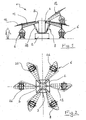
fig. 1 is a schematic side view of the device according to the invention; -
fig. 2 is a top view of the device shown infig. 1 ; -
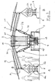
fig. 3 andfig. 4 are partially sectioned side views of the device with the vehicle at different heights; -
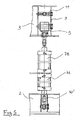
fig. 5 is a view of dual chamber piston according to the invention; -
fig. 6 is a scheme of a pneumatic system for operating the pistons of the device according to the invention; -
fig. 7 is a scheme of an hydraulic plant for operating the pistons of the device according to the invention; -
fig. 8 is a scheme of the control unit for operating a vehicle of the ride of the invention. - As shown in
figure 1 and 2 , the device of the invention is of the revolving ride type and comprises a central structure composed of abase 2 and a revolvingpart 3. The base comprises at least one motor (not shown) to make the ride revolve and at least part of the fluidic circuit which operates the above discussed arms. The fluidic circuit which is present onbase 2 comprises a motor to operate the means for pressurizing fluid, that means a compressor if a pneumatic circuit is used or a pump, preferably a variable displacement pump, if an hydraulic circuit is used. - The revolving
part 3 comprises part of the pneumatic or hydraulic system and a plurality ofarms 5 supporting a corresponding plurality ofvehicles 6. A cylinder 7, namely a dual-chamber cylinder, is also provided for eacharm 5 in order to operate saidarms 5. - In the embodiment shown in
fig. 3 ,4 and6 , in which a pneumatic circuit is described, on thebase 2 twomotors 4 and 4' are provided (fig. 3 ,4 and6 ) to operatecorrespondent compressors 18, while in the embodiment offig. 7 , which is referred to an hydraulic circuit, amotor 28 is present, which operates avariable displacement pump 29. - The
vehicle 6 is preferably in the form of two bicycles 6A and 6B positioned side by side, provided withpedals 8, and is surmounted by awing 12 with a shape similar to that of a hang-glider, but asymmetrical. The supporting structure 9 of thevehicle 6 is connected to theflange 10 of the revolvingpart 3 by means of thearm 5. The cylinder 7 is hinged on thearm 5 at its upper end, the lower end of the cylinder 7 being hinged to a flange 10' integral with thestructure 3. Above thearm 5 is anadditional arm 11, which extends from the supporting structure 9 of the vehicle, where it is hinged, to the above-mentionedflange 10 of the revolvingportion 3; the twoarms flange 10, a parallelogram which allows the vehicle to be tilted as it is raised, as can be seen in the figures, until reaching the maximum tilt value corresponding to the angle α offig. 4 . Said angle is preferably between 12 and 21 degrees and more preferably of approximately 16 degrees. - As mentioned above, the invention comprises means that can be moved by at least one passenger present on the
vehicle 6 at a measurable speed, means 13 for measuring the speed of the means moved, or operated, by the passenger and for generating a corresponding signal, as well as means for controlling the operation of the cylinders 7 according to the one or more signals generated by at least one measured speed. - With reference to
fig. 8 , in the embodiment shown the means that can be moved by the passenger consist of thepedals 8 of the bicycle. Since two bicycles are positioned side by side to form thevehicle 6, preferably both bicycles are connected to speed measuring means 13 to measure the speed at which thepedals 8 of the bicycle are moved, thus permitting the lifting of the arm even if only one passenger is present. The two bicycles are connected to themeans 13 preferably in a way that enables the measurement of the highest speed of the two bicycles, without interfering with their use by different passengers. This, for example, allows the device to be used simultaneously by an adult and a child. - The
means 13 are able to measure at least one speed of thepedals 8, i.e. they can operate in on/off mode and generate a signal if a pre-set and stored speed threshold is reached, or they can operate in proportional mode and generate signals corresponding to the speed at which the pedals are operated. Suitable means for on/off operation are, for example, phonic wheels (toothed wheels provided with a fixed proximity switch), centrifugal switches, magnetic systems and relative dedicated boards; suitable systems to generate proportional signals are dynamos, in particular speedometric dynamos, which generate a variable voltage. - The phonic wheel is a preferred solution because it is reliable in the long term and easy to operate. A suitable phonic wheel comprises a number of teeth in the range between 20 and 30.
- As shown in the scheme of
fig. 8 , the phonic wheel, or other means, 13, generates a signal which is sent to acentral control unit 14, to which theother vehicles 6 are connected and which is connected to theelectrovalves 15 which control the supply of fluid to the lifting cylinders. In the above-mentioned case, thevalves 15 are operated and switched to the open position only when the signal generated by the phonic wheel(s) 13 is higher than a pre-set value. - Each of the cylinders 7 is provided (
fig. 5 ) with a dual chamber, i.e. a lower smaller chamber referred to with 7A, and an upper larger chamber referred to with 7B.Chamber 7A has the function of lifting the vehicles when the ride starts working in order to avoid the contact with the ground, themain chamber 7B causes the lift and the descent of the arm according to the opening of the correspondent electrovalve 15, which is opened or closed by thecontrol unit 14 according to the signals coming to saidcontrol unit 14 from phonic wheels or other measurement means of the pedalling speed. - When the
electrovalve 15 is switched to the open position, a fluid (generally air) coming from one or more storage tanks is supplied to thecylinder 7B and the vehicle is raised; when the signal from 13 is below the pre-set value, thevalve 15 is closed and the cylinder moves down. - Preferably, the closing step of
valve 15 is also controlled by atimer 16 which maintains the supply of compressed air to thecylinder 7B even after the value of the signal generated by 13 has dropped below the pre-set threshold value. Said period of time is generally equal to a few seconds, for example four seconds, and prevents immediate lowering of the vehicle when the pedalling action is temporarily interrupted. In addition, the capacity of electrovalve 15 is regulated so as to generate a gradual filling and emptying of the corresponding chamber (or cylinder) of thepiston 7B and therefore a gradual raising and descent of thevehicle 6. -
Fig. 6 shows the pneumatic system according to the invention. Here twocompressors 18 operated by therelative motors 4 and 4' supply pressurized air to a circuit which comprises, on thefixed part 2 of the ride, together with the compressors, aspare tank 19, the remaining part of the circuit being generally housed on the revolving part of the ride. In one embodiment,motors 4 and 4' also cause the rotation ofpart 3 on thebase 2 for instance onbearings 17. - In particular, the circuit comprises
further tanks 20 which are connected by means of afilter 21 and apressure reducer 22 to an airflow distribution block 23. Theblock 23 is connected to theelectrovalves 15 which control the supply of thelarger chamber 7B, and also of afurther electrovalve 24 which controls, in a centralised and simultaneous way, the supply of air to asecond distribution block 25 which is directly connected to thesmaller chambers 7A. - The
smaller chamber 7A is fed with pressurized air when the ride is operated, so as to raise all thevehicles 6 to position A shown on the right offig. 3 : in this position thevehicles 6 can be rotated with the ride by thearms 5 without the passengers coming into contact with the ground. - The
larger chamber 7B is fed when the control means 14 have detected the signal with pre-set threshold value, or proportionally to the signal generated (for example if a dynamo is used to generate a proportional signal). When air is fed, thevehicle 6 is raised from the passenger boarding position A to position B offig. 3 and then to positions C and D offig. 4 . -
Fig. 7 shows an embodiment of hydraulic circuit according to the invention. As shown, amotor 28 operates apump 29 which draws from a tank 30 to which it can return all, nothing or part of the fluid drawn from it with line 31.Pump 29 is connected by means ofline 32 with all thesmaller chambers 7A by means of a single first electrovalve Ev1 which controls the supplying of oil to thechambers 7A of the cylinders 7. Thepump 29 is also connected withlarger chambers 7B of each cylinder 7 by means of correspondent electrovalves Ev2-Ev7, in a similar way to that above described for the embodiment concerning the hydraulic circuit. - The
larger chambers 7B of cylinders 7 are furthermore provided withaccumulators 33 to allow a gradual raising ofarms 5 when the signal of themeans 13 reaches the pre-set threshold. Anexhaust block 34 comprising an exchanger 35 completes the circuit. - The working of the device is similar to the one described above for the pneumatic circuit. The
motor 28 which operates thehydraulic pump 8 is always working and the machine cycle develops as follows: - 1) Start
- 2) Excitation of electrovalve Ev1: the lower jackets (short i.e. small chambers) 7A of cylinders 7 are fed and the arms raise from ground.
- 3) Starting of the rotation of the machine by means of the rotation motor, that, as above mentioned, is a standard electric motor and is not shown in the figures,
- 4) Depending on passengers' pedalling, one or more of the electrovalves Ev2-Ev7 excite (on/off), each independently from the others.
- To the excitement of electrovalve EvX corresponds a fluid delivery in the upper chamber (long) 7B of the correspondent cylinder 7 and a correspondent lifting of the
arm 5. To the dropping out of electrovalve EvX (no longer excited) corresponds an oil flow from upper chamber (long) 7B of the cylinder 7 to tank 30 and a corresponding lowering ofarm 5. - At the end of the cycle all valves Ev1, Ev2-Ev-7 are dropped out, arms lower and rotation is stopped at the same time.
- As in the previous case concerning the compressor, in the hydraulic circuit the
variable displacement pump 29 is always working by means ofmotor 28 and adjusts its capacity according to the use requirements. In other words, if all electrovalves Ev2-Ev7 are dropped out, pump supplies no capacity, if all Ev are simultaneously excited, that is if all passengers simultaneously pedal and generate required signal, it supplies maximum available supply. - As above mentioned, the signal generated in 13 and transmitted to the
control unit 14 is used to operate valve 15 (pneumatic or the electrovalved Ev2-Ev7) and not, as in the previous art, to operate motors. Thecylinder 7B, which causes the lifting or the lowering ofvehicle 6, receives air from one of thetanks 20, in which pressurized air coming from the compressor is put in, or it receives oil frompump 29 which draws it from tank 30. The said tanks or pump also feedsmaller cylinders 7A, which help the minimum lifting of the vehicle. The functioning ofmotors - In this way, that is by means of a pneumatic plant with storage tanks or by means of an hydraulic plant, it was possible to free the operation of motors from the signal connected with pedalling speed, said signal being instead connected, through
control unit 13, with the operation ofvalves 15 of lifting cylinders. Thanks to this it was possible to use only one or two motors for an embodiment as the shown one, which provides the presence of six vehicles with two seats each. In such embodiment motors are one with 12 Kw or two with 5,5 Kw and enable to reach 6 rpm (revolutions per minute) with an hourly capacity of up to 240 persons. - The
control unit 14 furthermore controls the operation of a further element, again according to the operating speed of thepedals 8. In this case the element is apropeller 26 which is operated by amotor 27 preferably in a proportional way to the speed of the pedals for an improved simulation of the "flight" speed of the vehicle.
Claims (10)
- A revolving ride (1) device comprising a plurality of arms (5) bearing a vehicle (6), and means for lifting said arms comprising lifting cylinders (7), whereby said lifting cylinders are dual-chamber cylinders (7A, 7B) and whereby the revolving ride device further comprises means (8) that can be moved by at least one passenger on the vehicle (6) at a measurable speed, means (13) for measuring said speed of said movable means and generating a corresponding signal and means (14, 15) for controlling operation of said cylinders (7) according to said at least one speed.
- Device as claimed in claim 1, wherein said means for controlling the operation of said cylinders comprises a control unit (14), a valve (15) which can be activated by said control unit and a timer (16) for delaying the activation of said valve (15).
- Device as claimed in claim 1 or 2 wherein said valve (15) is connected to a storage tank (20) of a pneumatic circuit.
- Device as claimed in claim 1 or 2 wherein said valve is connected to an hydraulic circuit comprising a motor and a variable displacement pump.
- Device as claimed in any claim 1 to 4, wherein said means (8) that can be moved by the passenger are bicycle pedals.
- Device as claimed in any claim 1 to 5, wherein said means (13) for measuring the speed of the movable means (8) comprise a phonic wheel that can be operated by the movable means.
- Device as claimed in any previous claim, wherein said vehicle (6) is connected to the revolving ride (1) by means of two arms (5, 11) positioned at different heights, said arms forming a parallelogram with said vehicle and said ride.
- Device as claimed in any claim 2 to 6, wherein said control unit (14) controls operation of at least one further device (27, 26) according to the signal received from said speed measuring means (13).
- Device as claimed in any previous claim, further comprising a dynamo to generate a proportional speed signal.
- A method to operate the lifting of at least one arm of a revolving ride device according to any previous claim, characterised in that it comprises the steps of pressurizing a fluidic circuit comprising dual chamber cylinders (7), measuring the operating speed of the user-movable means (8, 13) and controlling the opening of a valve (15) provided on a chamber (7B) of said cylinders when said operating speed exceeds a pre-set value.
Applications Claiming Priority (2)
| Application Number | Priority Date | Filing Date | Title |
|---|---|---|---|
| ITMI20062185 ITMI20062185A1 (en) | 2006-11-14 | 2006-11-14 | FUN ROTARY DEVICE FOR FUN |
| PCT/IB2007/003496 WO2008059356A2 (en) | 2006-11-14 | 2007-11-14 | Amusement merry-go-round device |
Publications (2)
| Publication Number | Publication Date |
|---|---|
| EP2081658A2 EP2081658A2 (en) | 2009-07-29 |
| EP2081658B1 true EP2081658B1 (en) | 2014-12-17 |
Family
ID=39249844
Family Applications (1)
| Application Number | Title | Priority Date | Filing Date |
|---|---|---|---|
| EP07825672.4A Active EP2081658B1 (en) | 2006-11-14 | 2007-11-14 | Amusement merry-go-round device |
Country Status (3)
| Country | Link |
|---|---|
| EP (1) | EP2081658B1 (en) |
| IT (1) | ITMI20062185A1 (en) |
| WO (1) | WO2008059356A2 (en) |
Cited By (1)
| Publication number | Priority date | Publication date | Assignee | Title |
|---|---|---|---|---|
| EP4552713A1 (en) * | 2023-11-13 | 2025-05-14 | Antonio Zamperla S.p.A. | Oscillating amusement ride |
Families Citing this family (9)
| Publication number | Priority date | Publication date | Assignee | Title |
|---|---|---|---|---|
| US8303426B2 (en) | 2010-08-11 | 2012-11-06 | Disney Enterprises, Inc. | Round ride with passenger-initiated motion profile |
| US8317632B2 (en) | 2010-09-08 | 2012-11-27 | Disney Enterprises, Inc. | High and low flyer ride |
| EP2632794A4 (en) | 2010-10-26 | 2014-05-07 | Aba Science Play Ltd | Helicopter amusement apparatus |
| KR101262339B1 (en) * | 2011-06-24 | 2013-05-08 | 안영남 | Multi flight play apparatus |
| WO2015070932A1 (en) * | 2013-11-18 | 2015-05-21 | Antonio Zamperla S.P.A. | Amusement ride |
| CN106999776A (en) | 2014-11-17 | 2017-08-01 | 安东尼奥赞佩拉股份公司 | Carriers for rotary carousels |
| EP3538233B1 (en) | 2016-11-11 | 2020-09-09 | Antonio Zamperla S.p.A. | Trackless amusement ride |
| IT201900023301A1 (en) * | 2019-12-06 | 2021-06-06 | Zamperla Antonio Spa | Carousel seat and system for boarding / alighting passengers onto / from at least one seat |
| US11583780B2 (en) * | 2020-07-13 | 2023-02-21 | Universal City Studios Llc | Carousel ride systems |
Family Cites Families (3)
| Publication number | Priority date | Publication date | Assignee | Title |
|---|---|---|---|---|
| US2922648A (en) * | 1956-07-02 | 1960-01-26 | Jr David E Bradley | Amusement ride |
| FR2618690B1 (en) * | 1987-07-28 | 1991-02-01 | Roche Jean Jose | ELEVATOR WITH ASCENDING EFFECT |
| IT1310948B1 (en) * | 1999-03-09 | 2002-02-27 | Memo Park Di Incerti Fornaciar | FUN MACHINE WITH MOBILE STATION. |
-
2006
- 2006-11-14 IT ITMI20062185 patent/ITMI20062185A1/en unknown
-
2007
- 2007-11-14 WO PCT/IB2007/003496 patent/WO2008059356A2/en not_active Ceased
- 2007-11-14 EP EP07825672.4A patent/EP2081658B1/en active Active
Cited By (1)
| Publication number | Priority date | Publication date | Assignee | Title |
|---|---|---|---|---|
| EP4552713A1 (en) * | 2023-11-13 | 2025-05-14 | Antonio Zamperla S.p.A. | Oscillating amusement ride |
Also Published As
| Publication number | Publication date |
|---|---|
| ITMI20062185A1 (en) | 2008-05-15 |
| EP2081658A2 (en) | 2009-07-29 |
| WO2008059356A3 (en) | 2008-07-10 |
| WO2008059356A2 (en) | 2008-05-22 |
Similar Documents
| Publication | Publication Date | Title |
|---|---|---|
| EP2081658A2 (en) | Amusement merry-go-round device | |
| CN102036874B (en) | Mobile body and its control method | |
| NL1035933C (en) | System, lifting column and method for energy-efficient lifting and lowering a load. | |
| CN201076593Y (en) | Massage chair | |
| JP2000508614A (en) | Method and apparatus for controlling a hydraulic lift | |
| CN101511667B (en) | Traveling vehicle | |
| JP2002020059A (en) | Elevator with counterweight also serving as plunger of drive aeromechanic device generating and controlling movement of elevator | |
| EP0824032B1 (en) | Device for accelerating and decelerating objects | |
| KR102055744B1 (en) | Drifting electric board | |
| CN104981277A (en) | Water amusement ride having floating body | |
| CN206189934U (en) | Two -layer parking equipment's of single motor guide pulley commutation drive mechanism | |
| US20180085675A1 (en) | Amusement ride for hang gliding simulation | |
| US5820469A (en) | Flying vehicle ride | |
| KR101626495B1 (en) | Air-cushion vehicle for amusement | |
| EP3221019B1 (en) | Vehicle for rotating carousel | |
| WO2001008767A1 (en) | Track-mounted ride powered by compressed gas | |
| KR101768808B1 (en) | Playing apparatus | |
| KR20090084620A (en) | Flying rides | |
| JPH08301556A (en) | Elevator | |
| ES2244390T3 (en) | ATTRACTION MACHINE WITH MOBILE SEAT. | |
| EP4552713B1 (en) | Oscillating amusement ride | |
| JP2002011257A (en) | Play facility and traveling body for play facility | |
| CN201082348Y (en) | Combined motion recreational machine | |
| JP4649660B2 (en) | Leg support device and vehicle seat provided with the leg support device | |
| ITUB20154882A1 (en) | ROTATING GIOSTRA |
Legal Events
| Date | Code | Title | Description |
|---|---|---|---|
| PUAI | Public reference made under article 153(3) epc to a published international application that has entered the european phase |
Free format text: ORIGINAL CODE: 0009012 |
|
| 17P | Request for examination filed |
Effective date: 20090504 |
|
| AK | Designated contracting states |
Kind code of ref document: A2 Designated state(s): AT BE BG CH CY CZ DE DK EE ES FI FR GB GR HU IE IS IT LI LT LU LV MC MT NL PL PT RO SE SI SK TR |
|
| DAX | Request for extension of the european patent (deleted) | ||
| GRAP | Despatch of communication of intention to grant a patent |
Free format text: ORIGINAL CODE: EPIDOSNIGR1 |
|
| INTG | Intention to grant announced |
Effective date: 20131015 |
|
| GRAP | Despatch of communication of intention to grant a patent |
Free format text: ORIGINAL CODE: EPIDOSNIGR1 |
|
| INTG | Intention to grant announced |
Effective date: 20140704 |
|
| GRAS | Grant fee paid |
Free format text: ORIGINAL CODE: EPIDOSNIGR3 |
|
| GRAA | (expected) grant |
Free format text: ORIGINAL CODE: 0009210 |
|
| AK | Designated contracting states |
Kind code of ref document: B1 Designated state(s): AT BE BG CH CY CZ DE DK EE ES FI FR GB GR HU IE IS IT LI LT LU LV MC MT NL PL PT RO SE SI SK TR |
|
| REG | Reference to a national code |
Ref country code: GB Ref legal event code: FG4D |
|
| REG | Reference to a national code |
Ref country code: CH Ref legal event code: EP |
|
| REG | Reference to a national code |
Ref country code: IE Ref legal event code: FG4D |
|
| REG | Reference to a national code |
Ref country code: AT Ref legal event code: REF Ref document number: 701465 Country of ref document: AT Kind code of ref document: T Effective date: 20150115 Ref country code: CH Ref legal event code: NV Representative=s name: KAMINSKI HARMANN PATENTANWAELTE AG, LI |
|
| REG | Reference to a national code |
Ref country code: NL Ref legal event code: T3 |
|
| REG | Reference to a national code |
Ref country code: DE Ref legal event code: R096 Ref document number: 602007039733 Country of ref document: DE Effective date: 20150129 |
|
| PG25 | Lapsed in a contracting state [announced via postgrant information from national office to epo] |
Ref country code: LT Free format text: LAPSE BECAUSE OF FAILURE TO SUBMIT A TRANSLATION OF THE DESCRIPTION OR TO PAY THE FEE WITHIN THE PRESCRIBED TIME-LIMIT Effective date: 20141217 Ref country code: FI Free format text: LAPSE BECAUSE OF FAILURE TO SUBMIT A TRANSLATION OF THE DESCRIPTION OR TO PAY THE FEE WITHIN THE PRESCRIBED TIME-LIMIT Effective date: 20141217 |
|
| REG | Reference to a national code |
Ref country code: LT Ref legal event code: MG4D |
|
| PG25 | Lapsed in a contracting state [announced via postgrant information from national office to epo] |
Ref country code: LV Free format text: LAPSE BECAUSE OF FAILURE TO SUBMIT A TRANSLATION OF THE DESCRIPTION OR TO PAY THE FEE WITHIN THE PRESCRIBED TIME-LIMIT Effective date: 20141217 Ref country code: SE Free format text: LAPSE BECAUSE OF FAILURE TO SUBMIT A TRANSLATION OF THE DESCRIPTION OR TO PAY THE FEE WITHIN THE PRESCRIBED TIME-LIMIT Effective date: 20141217 Ref country code: GR Free format text: LAPSE BECAUSE OF FAILURE TO SUBMIT A TRANSLATION OF THE DESCRIPTION OR TO PAY THE FEE WITHIN THE PRESCRIBED TIME-LIMIT Effective date: 20150318 |
|
| REG | Reference to a national code |
Ref country code: AT Ref legal event code: MK05 Ref document number: 701465 Country of ref document: AT Kind code of ref document: T Effective date: 20141217 |
|
| PG25 | Lapsed in a contracting state [announced via postgrant information from national office to epo] |
Ref country code: SK Free format text: LAPSE BECAUSE OF FAILURE TO SUBMIT A TRANSLATION OF THE DESCRIPTION OR TO PAY THE FEE WITHIN THE PRESCRIBED TIME-LIMIT Effective date: 20141217 Ref country code: CZ Free format text: LAPSE BECAUSE OF FAILURE TO SUBMIT A TRANSLATION OF THE DESCRIPTION OR TO PAY THE FEE WITHIN THE PRESCRIBED TIME-LIMIT Effective date: 20141217 Ref country code: ES Free format text: LAPSE BECAUSE OF FAILURE TO SUBMIT A TRANSLATION OF THE DESCRIPTION OR TO PAY THE FEE WITHIN THE PRESCRIBED TIME-LIMIT Effective date: 20141217 Ref country code: EE Free format text: LAPSE BECAUSE OF FAILURE TO SUBMIT A TRANSLATION OF THE DESCRIPTION OR TO PAY THE FEE WITHIN THE PRESCRIBED TIME-LIMIT Effective date: 20141217 Ref country code: RO Free format text: LAPSE BECAUSE OF FAILURE TO SUBMIT A TRANSLATION OF THE DESCRIPTION OR TO PAY THE FEE WITHIN THE PRESCRIBED TIME-LIMIT Effective date: 20141217 |
|
| PG25 | Lapsed in a contracting state [announced via postgrant information from national office to epo] |
Ref country code: IS Free format text: LAPSE BECAUSE OF FAILURE TO SUBMIT A TRANSLATION OF THE DESCRIPTION OR TO PAY THE FEE WITHIN THE PRESCRIBED TIME-LIMIT Effective date: 20150417 Ref country code: PL Free format text: LAPSE BECAUSE OF FAILURE TO SUBMIT A TRANSLATION OF THE DESCRIPTION OR TO PAY THE FEE WITHIN THE PRESCRIBED TIME-LIMIT Effective date: 20141217 Ref country code: AT Free format text: LAPSE BECAUSE OF FAILURE TO SUBMIT A TRANSLATION OF THE DESCRIPTION OR TO PAY THE FEE WITHIN THE PRESCRIBED TIME-LIMIT Effective date: 20141217 |
|
| REG | Reference to a national code |
Ref country code: DE Ref legal event code: R097 Ref document number: 602007039733 Country of ref document: DE |
|
| PLBE | No opposition filed within time limit |
Free format text: ORIGINAL CODE: 0009261 |
|
| STAA | Information on the status of an ep patent application or granted ep patent |
Free format text: STATUS: NO OPPOSITION FILED WITHIN TIME LIMIT |
|
| PG25 | Lapsed in a contracting state [announced via postgrant information from national office to epo] |
Ref country code: DK Free format text: LAPSE BECAUSE OF FAILURE TO SUBMIT A TRANSLATION OF THE DESCRIPTION OR TO PAY THE FEE WITHIN THE PRESCRIBED TIME-LIMIT Effective date: 20141217 |
|
| 26N | No opposition filed |
Effective date: 20150918 |
|
| PG25 | Lapsed in a contracting state [announced via postgrant information from national office to epo] |
Ref country code: SI Free format text: LAPSE BECAUSE OF FAILURE TO SUBMIT A TRANSLATION OF THE DESCRIPTION OR TO PAY THE FEE WITHIN THE PRESCRIBED TIME-LIMIT Effective date: 20141217 |
|
| PG25 | Lapsed in a contracting state [announced via postgrant information from national office to epo] |
Ref country code: BE Free format text: LAPSE BECAUSE OF FAILURE TO SUBMIT A TRANSLATION OF THE DESCRIPTION OR TO PAY THE FEE WITHIN THE PRESCRIBED TIME-LIMIT Effective date: 20141217 |
|
| PG25 | Lapsed in a contracting state [announced via postgrant information from national office to epo] |
Ref country code: MC Free format text: LAPSE BECAUSE OF FAILURE TO SUBMIT A TRANSLATION OF THE DESCRIPTION OR TO PAY THE FEE WITHIN THE PRESCRIBED TIME-LIMIT Effective date: 20141217 Ref country code: LU Free format text: LAPSE BECAUSE OF FAILURE TO SUBMIT A TRANSLATION OF THE DESCRIPTION OR TO PAY THE FEE WITHIN THE PRESCRIBED TIME-LIMIT Effective date: 20151114 |
|
| GBPC | Gb: european patent ceased through non-payment of renewal fee |
Effective date: 20151114 |
|
| REG | Reference to a national code |
Ref country code: IE Ref legal event code: MM4A |
|
| REG | Reference to a national code |
Ref country code: FR Ref legal event code: ST Effective date: 20160729 |
|
| REG | Reference to a national code |
Ref country code: CH Ref legal event code: NV Representative=s name: FABIANO, FRANKE AND MGT SAGL, CH |
|
| PG25 | Lapsed in a contracting state [announced via postgrant information from national office to epo] |
Ref country code: IE Free format text: LAPSE BECAUSE OF NON-PAYMENT OF DUE FEES Effective date: 20151114 Ref country code: GB Free format text: LAPSE BECAUSE OF NON-PAYMENT OF DUE FEES Effective date: 20151114 |
|
| PG25 | Lapsed in a contracting state [announced via postgrant information from national office to epo] |
Ref country code: FR Free format text: LAPSE BECAUSE OF NON-PAYMENT OF DUE FEES Effective date: 20151130 |
|
| PG25 | Lapsed in a contracting state [announced via postgrant information from national office to epo] |
Ref country code: HU Free format text: LAPSE BECAUSE OF FAILURE TO SUBMIT A TRANSLATION OF THE DESCRIPTION OR TO PAY THE FEE WITHIN THE PRESCRIBED TIME-LIMIT; INVALID AB INITIO Effective date: 20071114 Ref country code: BG Free format text: LAPSE BECAUSE OF FAILURE TO SUBMIT A TRANSLATION OF THE DESCRIPTION OR TO PAY THE FEE WITHIN THE PRESCRIBED TIME-LIMIT Effective date: 20141217 |
|
| PG25 | Lapsed in a contracting state [announced via postgrant information from national office to epo] |
Ref country code: CY Free format text: LAPSE BECAUSE OF FAILURE TO SUBMIT A TRANSLATION OF THE DESCRIPTION OR TO PAY THE FEE WITHIN THE PRESCRIBED TIME-LIMIT Effective date: 20141217 |
|
| PG25 | Lapsed in a contracting state [announced via postgrant information from national office to epo] |
Ref country code: MT Free format text: LAPSE BECAUSE OF FAILURE TO SUBMIT A TRANSLATION OF THE DESCRIPTION OR TO PAY THE FEE WITHIN THE PRESCRIBED TIME-LIMIT Effective date: 20141217 |
|
| PG25 | Lapsed in a contracting state [announced via postgrant information from national office to epo] |
Ref country code: PT Free format text: LAPSE BECAUSE OF FAILURE TO SUBMIT A TRANSLATION OF THE DESCRIPTION OR TO PAY THE FEE WITHIN THE PRESCRIBED TIME-LIMIT Effective date: 20141217 |
|
| REG | Reference to a national code |
Ref country code: CH Ref legal event code: PCAR Free format text: NEW ADDRESS: PIAZZETTA SAN CARLO 2, 6900 LUGANO (CH) |
|
| PGFP | Annual fee paid to national office [announced via postgrant information from national office to epo] |
Ref country code: NL Payment date: 20201014 Year of fee payment: 14 |
|
| PGFP | Annual fee paid to national office [announced via postgrant information from national office to epo] |
Ref country code: CH Payment date: 20201006 Year of fee payment: 14 |
|
| REG | Reference to a national code |
Ref country code: CH Ref legal event code: PL |
|
| REG | Reference to a national code |
Ref country code: NL Ref legal event code: MM Effective date: 20211201 |
|
| PG25 | Lapsed in a contracting state [announced via postgrant information from national office to epo] |
Ref country code: NL Free format text: LAPSE BECAUSE OF NON-PAYMENT OF DUE FEES Effective date: 20211201 |
|
| P01 | Opt-out of the competence of the unified patent court (upc) registered |
Effective date: 20230527 |
|
| PG25 | Lapsed in a contracting state [announced via postgrant information from national office to epo] |
Ref country code: LI Free format text: LAPSE BECAUSE OF NON-PAYMENT OF DUE FEES Effective date: 20220630 Ref country code: CH Free format text: LAPSE BECAUSE OF NON-PAYMENT OF DUE FEES Effective date: 20220630 |
|
| PGFP | Annual fee paid to national office [announced via postgrant information from national office to epo] |
Ref country code: DE Payment date: 20251119 Year of fee payment: 19 |
|
| PGFP | Annual fee paid to national office [announced via postgrant information from national office to epo] |
Ref country code: IT Payment date: 20251126 Year of fee payment: 19 |
|
| PGFP | Annual fee paid to national office [announced via postgrant information from national office to epo] |
Ref country code: TR Payment date: 20251110 Year of fee payment: 19 |