EP2081043A2 - Navigation system with apparatus for detecting accuracy failures - Google Patents
Navigation system with apparatus for detecting accuracy failures Download PDFInfo
- Publication number
- EP2081043A2 EP2081043A2 EP09150448A EP09150448A EP2081043A2 EP 2081043 A2 EP2081043 A2 EP 2081043A2 EP 09150448 A EP09150448 A EP 09150448A EP 09150448 A EP09150448 A EP 09150448A EP 2081043 A2 EP2081043 A2 EP 2081043A2
- Authority
- EP
- European Patent Office
- Prior art keywords
- solution
- processor
- navigation
- protection level
- level value
- Prior art date
- Legal status (The legal status is an assumption and is not a legal conclusion. Google has not performed a legal analysis and makes no representation as to the accuracy of the status listed.)
- Withdrawn
Links
Images


Classifications
-
- G—PHYSICS
- G01—MEASURING; TESTING
- G01S—RADIO DIRECTION-FINDING; RADIO NAVIGATION; DETERMINING DISTANCE OR VELOCITY BY USE OF RADIO WAVES; LOCATING OR PRESENCE-DETECTING BY USE OF THE REFLECTION OR RERADIATION OF RADIO WAVES; ANALOGOUS ARRANGEMENTS USING OTHER WAVES
- G01S19/00—Satellite radio beacon positioning systems; Determining position, velocity or attitude using signals transmitted by such systems
- G01S19/01—Satellite radio beacon positioning systems transmitting time-stamped messages, e.g. GPS [Global Positioning System], GLONASS [Global Orbiting Navigation Satellite System] or GALILEO
- G01S19/13—Receivers
- G01S19/20—Integrity monitoring, fault detection or fault isolation of space segment
Definitions
- navigation systems should also be able to provide users with timely warnings indicating when it is not safe/acceptable to use the navigation solution.
- a navigation system with this capability is, by definition, a navigation system with integrity.
- Satellite failures can occur which result in unpredictable deterministic range errors on the failing satellite. Satellite failures are rare (i.e., on the order of 1 every year), but safety-critical navigation systems must account for these errors.
- navigation systems e.g ., GPS Receivers
- position solution i.e ., horizontal position and altitude
- other navigation parameters such as ground speed and vertical velocity.
- a navigation system for a vehicle having a receiver operable to receive a plurality of signals from a plurality of transmitters includes a processor and a memory device.
- the memory device has stored thereon machine-readable instructions that, when executed by the processor, enable the processor to determine a set of pseudo-range measurements derived from the plurality of signals, employing at least one Kalman filter process, determine from the measurements an error covariance matrix for a main navigation solution, and using a solution separation technique, determine at least one protection level value based on the error covariance matrix.
- FIG. 1 shows a first navigation system incorporating embodiments of the present invention
- FIG. 2 shows a second navigation system incorporating embodiments of the present invention
- FIG. 3 shows a process according to an embodiment of the invention
- FIG. 4 shows a process according to the embodiment illustrated in FIG 3 ;
- FIG. 5 shows a process according to the embodiment illustrated in FIG 3 .
- An embodiment builds on many of the concepts applied to position integrity in order to provide integrity on the following navigation states: North Velocity, East Velocity, Ground Speed, Vertical Speed, Flight Path Angle, and Track Angle.
- One or more embodiments may include a bank of filters/solutions (whether Kalman Filter or Least Squares) that may be composed of a main solution that processes all satellite measurements along with a set of sub-solutions; where each sub-solution processes one satellite fewer than the main solution.
- filters/solutions whether Kalman Filter or Least Squares
- Navigation systems primarily employ one of the following implementations in order to calculate a navigation solution: a Kalman Filter or a Least Squares Solution.
- GPS receivers which have GPS satellite measurements (and possibly altitude aiding) use a Least Squares solution while Hybrid Inertial/GPS systems use a Kalman Filter. Both methods use a recursive algorithm which provides a solution via a weighted combination of predictions and measurements.
- a Least Squares Solution possesses minimal prediction capability and is therefore heavily influenced by measurements (in fact the weighting factor on predictions in a Least Squares Solution approaches zero with each iteration).
- a Kalman Filter on the other hand is able to take advantage of additional information about the problem; such as additional measurement data (e.g., inertial data) or additional information about system noise and/or measurement noise. This allows the Kalman Filter to continuously vary its weighting on its own predictions versus measurement inputs (this may be done via the Kalman Gain). A Kalman Filter with very low confidence in its own predictions (i.e., a very large Kalman Gain) will behave much like a Least Squares Solution.
- the Error Covariance Matrix may be a critical component of any fault detection and integrity limit algorithm.
- P may be a fundamental part of the recursive Kalman Filter process.
- a Kalman Filter navigation solution may not be produced without the P matrix.
- a Least-Squares solution calculation of the actual navigation solution may not require use of an error covariance matrix. Therefore, a Least Squares Solution may only produce a P matrix if it is desired to provide integrity with the navigation solution.
- Calculation of a P matrix for a Least Squares solution is based on the satellite geometry (line of sight from user to all satellites in view) and an estimate of the errors on the satellite measurements.
- FIG. 1 shows a radio navigation system 10 incorporating features of an embodiment of the present invention.
- the system includes several transmitters 1-N and user set 12.
- Transmitters 1-N may be a subset of the NAVSTAR GPS constellation of satellite transmitters, with each transmitter visible from the antenna of user set 12.
- Transmitters 1-N broadcast N respective signals indicating respective transmitter positions and signal transmission times to user set 12.
- User set 12 mounted to an aircraft (not shown), includes receiver 14, processor 16, and processor memory 18.
- Receiver 14, preferably NAVSTAR GPS compatible receives the signals, extracts the position and time data, and provides pseudorange measurements to processor 16. From the pseudorange measurements, processor 16 can derive a position solution for the user set.
- the satellites can transmit their positions in World Geodetic System of 1984 (WGS-84) coordinates, a Cartesian earth-centered earth-fixed system, an embodiment determines the position solution in a local reference frame L, which is level with the north-east coordinate plane and tangential to the Earth. This frame choice, however, is not critical, since it is well-understood how to transform coordinates from one frame to another.
- Processor 16 can also use the pseudorange measurements to detect satellite transmitter failures and to determine a worst-case error, or protection limit, both of which it outputs with the position solution to flight management system 20.
- Flight management system 20 compares the protection limit to an alarm limit corresponding to a particular aircraft flight phase. For example, during a pre-landing flight phase, such as nonprecision approach, the alarm limit (or allowable radial error) may be 0.3 nautical miles, but during a less-demanding oceanic flight phase, the alarm limit may be 2-10 nautical miles.
- the flight management system If the protection limit exceeds the alarm limit, the flight management system, or its equivalent, announces or signals an integrity failure to a navigational display (not shown) in the cockpit of the aircraft.
- the processor also signals whether it has detected any satellite transmitter failures.
- a second embodiment extends the radio navigation system 10 of FIG. 1 with the addition of inertial reference unit 22 for providing inertial data to processor 16 and pressure altitude sensor 27 for providing altitude data to processor 16.
- the resulting combination constitutes a hybrid navigation system 30.
- Altitude sensor 27 can also provide data to stabilize inertial reference unit, as known in the art, but for clarity the connection is not shown here.
- Inertial reference unit 22 mounted to the aircraft (not shown), preferably includes three accelerometers 24a-24c for measuring acceleration in three dimensions and three gyroscopes 26a-26c for measuring angular orientation, or attitude, relative a reference plane.
- Inertial reference unit 22 also includes inertial processor 25 which determines an inertial position solution r i , preferably a three-element vector in an earth-fixed reference frame.
- Inertial processor 26 also preferably converts the acceleration data into raw acceleration vector a raw and attitude data into raw angular velocity vector ⁇ raw .
- the preferred angular velocity vector defines the rotation of the body frame (fixed to the aircraft) in three dimensions, and the preferred inertial acceleration defines the three components of acceleration in body frame coordinates.
- Inertial processor 26 also determines a transformation matrix C for transforming body frame coordinates to local vertical frame L, a three-element rotation vector ⁇ IE which describes rotation of the earth-based frame E versus inertial frame I transformed to L frame, and rotation vector ⁇ EL which describes rotation of the L frame versus the earth-fixed frame E transformed to L frame.
- a transformation matrix C for transforming body frame coordinates to local vertical frame L
- ⁇ IE which describes rotation of the earth-based frame E versus inertial frame I transformed to L frame
- rotation vector ⁇ EL which describes rotation of the L frame versus the earth-fixed frame E transformed to L frame.
- Kalman Filters provide a solution based on a weighted combination of predictions and measurements.
- An embodiment of the invention involves the processor 16 determining integrity for: North Velocity, East Velocity, Groundspeed, Vertical Velocity, track angle, and flight path angle based on a hybrid solution which blends multiple position measurements via a Kalman Filter (e.g., GPS measurements blended with position/velocity data from an Inertial Reference System).
- An embodiment of the invention employs principles of a snapshot solution separation algorithm described in commonly owned U.S. Patent Application No. (Attorney Docket No.
- FIG. 3 illustrates a process 300, according to an embodiment of the invention, that can be implemented in one or both of systems 10 and 30.
- the process 300 is illustrated as a set of operations or steps shown as discrete blocks.
- the process 300 may be implemented in any suitable hardware, software, firmware, or combination thereof.
- the process 300 may be implemented in computer-executable instructions that can be transferred from one electronic device to a second electronic device via a communications medium.
- the order in which the operations are described is not to be necessarily construed as a limitation.
- the processor 16 determines an error state covariance matrix P used for a solution separation process described hereinafter.
- the error covariance matrix P may be determined as a result of a recursive Kalman Filter process illustrated and described in greater detail with reference to FIG. 4 . Note that ⁇ ⁇ x ⁇ k - represents the error state and P k - the error state covariance from a previous iteration of the recursive Kalman Filter process.
- H k ⁇ ⁇ ⁇ x ⁇ k - represents the Kalman Filter's prediction of the current measurements.
- the difference ⁇ ⁇ z k - H k ⁇ ⁇ ⁇ x ⁇ k - may be referred to as the innovations or measurement residuals.
- the processor 16 performs a solution separation process.
- VVPL j D j vert + a j vert
- HVPL and VVPL are based on the max values for all main/sub-solution combinations.
- ⁇ d j horz and ⁇ horz_ max are based on the error covariance matrices (using the horizontal and vertical velocity states) calculated for the main and sub-solutions at block 450 discussed above.
- the processor 16 calculates track angle, and flight path angle integrity values for hybrid solution.
- VVPL represents the hybrid integrity on the vertical velocity.
Landscapes
- Engineering & Computer Science (AREA)
- Radar, Positioning & Navigation (AREA)
- Remote Sensing (AREA)
- Computer Security & Cryptography (AREA)
- Computer Networks & Wireless Communication (AREA)
- Physics & Mathematics (AREA)
- General Physics & Mathematics (AREA)
- Position Fixing By Use Of Radio Waves (AREA)
- Navigation (AREA)
Abstract
A navigation system (12) for a vehicle having a receiver (14) operable to receive a plurality of signals from a plurality of transmitters includes a processor (16) and a memory device (18). The memory device (18) has stored thereon machine-readable instructions that, when executed by the processor, enable the processor (16) to determine a set of pseudo-range measurements derived from the plurality of signals, employing at least one Kalman filter process, determine from the measurements an error covariance matrix for a main navigation solution, and using a solution separation technique, determine at least one protection level value based on sed on the error covariance matrix.
Description
- In addition to providing a navigation solution, navigation systems should also be able to provide users with timely warnings indicating when it is not safe/acceptable to use the navigation solution. A navigation system with this capability is, by definition, a navigation system with integrity.
- With GPS for example, satellite failures can occur which result in unpredictable deterministic range errors on the failing satellite. Satellite failures are rare (i.e., on the order of 1 every year), but safety-critical navigation systems must account for these errors. Typically, navigation systems (e.g., GPS Receivers) provide integrity on their position solution (i.e., horizontal position and altitude), but do not provide integrity on other navigation parameters, such as ground speed and vertical velocity.
- In an embodiment of the invention, a navigation system for a vehicle having a receiver operable to receive a plurality of signals from a plurality of transmitters includes a processor and a memory device. The memory device has stored thereon machine-readable instructions that, when executed by the processor, enable the processor to determine a set of pseudo-range measurements derived from the plurality of signals, employing at least one Kalman filter process, determine from the measurements an error covariance matrix for a main navigation solution, and using a solution separation technique, determine at least one protection level value based on the error covariance matrix.
- Preferred and alternative embodiments of the present invention are described in detail below with reference to the following drawings.
-
FIG. 1 shows a first navigation system incorporating embodiments of the present invention; and -
FIG. 2 shows a second navigation system incorporating embodiments of the present invention; -
FIG. 3 shows a process according to an embodiment of the invention; -
FIG. 4 shows a process according to the embodiment illustrated inFIG 3 ; and -
FIG. 5 shows a process according to the embodiment illustrated inFIG 3 . - An embodiment builds on many of the concepts applied to position integrity in order to provide integrity on the following navigation states: North Velocity, East Velocity, Ground Speed, Vertical Speed, Flight Path Angle, and Track Angle.
- One or more embodiments may include a bank of filters/solutions (whether Kalman Filter or Least Squares) that may be composed of a main solution that processes all satellite measurements along with a set of sub-solutions; where each sub-solution processes one satellite fewer than the main solution.
- Navigation systems primarily employ one of the following implementations in order to calculate a navigation solution: a Kalman Filter or a Least Squares Solution. In general, GPS receivers which have GPS satellite measurements (and possibly altitude aiding) use a Least Squares solution while Hybrid Inertial/GPS systems use a Kalman Filter. Both methods use a recursive algorithm which provides a solution via a weighted combination of predictions and measurements. However, a Least Squares Solution possesses minimal prediction capability and is therefore heavily influenced by measurements (in fact the weighting factor on predictions in a Least Squares Solution approaches zero with each iteration). A Kalman Filter on the other hand is able to take advantage of additional information about the problem; such as additional measurement data (e.g., inertial data) or additional information about system noise and/or measurement noise. This allows the Kalman Filter to continuously vary its weighting on its own predictions versus measurement inputs (this may be done via the Kalman Gain). A Kalman Filter with very low confidence in its own predictions (i.e., a very large Kalman Gain) will behave much like a Least Squares Solution.
- The Error Covariance Matrix, often denoted by the symbol "P," within a navigation system represents the standard deviation of the error state estimates within a navigation solution. For example, given a 3x3 matrix representing the error covariance for the x, y, and z velocity states within a Kalman filter:

- We would expect (with a properly modeled Kalman Filter) that the absolute value of the difference between the true ground speed and the Kalman Filter's ground speed would not exceed


- The Error Covariance Matrix may be a critical component of any fault detection and integrity limit algorithm. For a Kalman Filter, P may be a fundamental part of the recursive Kalman Filter process. A Kalman Filter navigation solution may not be produced without the P matrix. With a Least-Squares solution, calculation of the actual navigation solution may not require use of an error covariance matrix. Therefore, a Least Squares Solution may only produce a P matrix if it is desired to provide integrity with the navigation solution. Calculation of a P matrix for a Least Squares solution is based on the satellite geometry (line of sight from user to all satellites in view) and an estimate of the errors on the satellite measurements.
- Once a navigation system has an error covariance matrix along with its actual navigation solution, fault detection and calculation of integrity can be performed via Solution Separation or Parity Space Based techniques.
-
FIG. 1 shows a radio navigation system 10 incorporating features of an embodiment of the present invention. The system includes several transmitters 1-N and user set 12. Transmitters 1-N may be a subset of the NAVSTAR GPS constellation of satellite transmitters, with each transmitter visible from the antenna of user set 12. Transmitters 1-N broadcast N respective signals indicating respective transmitter positions and signal transmission times to user set 12. -
User set 12, mounted to an aircraft (not shown), includes receiver 14,processor 16, andprocessor memory 18. Receiver 14, preferably NAVSTAR GPS compatible, receives the signals, extracts the position and time data, and provides pseudorange measurements toprocessor 16. From the pseudorange measurements,processor 16 can derive a position solution for the user set. Although the satellites can transmit their positions in World Geodetic System of 1984 (WGS-84) coordinates, a Cartesian earth-centered earth-fixed system, an embodiment determines the position solution in a local reference frame L, which is level with the north-east coordinate plane and tangential to the Earth. This frame choice, however, is not critical, since it is well-understood how to transform coordinates from one frame to another. -
Processor 16 can also use the pseudorange measurements to detect satellite transmitter failures and to determine a worst-case error, or protection limit, both of which it outputs with the position solution toflight management system 20.Flight management system 20 compares the protection limit to an alarm limit corresponding to a particular aircraft flight phase. For example, during a pre-landing flight phase, such as nonprecision approach, the alarm limit (or allowable radial error) may be 0.3 nautical miles, but during a less-demanding oceanic flight phase, the alarm limit may be 2-10 nautical miles. (For more details on these limits, see RTCA publication DO-208, which is incorporated herein by reference.) If the protection limit exceeds the alarm limit, the flight management system, or its equivalent, announces or signals an integrity failure to a navigational display (not shown) in the cockpit of the aircraft. The processor also signals whether it has detected any satellite transmitter failures. - As shown in
FIG. 2 , a second embodiment extends the radio navigation system 10 ofFIG. 1 with the addition ofinertial reference unit 22 for providing inertial data toprocessor 16 and pressure altitude sensor 27 for providing altitude data toprocessor 16. The resulting combination constitutes a hybrid navigation system 30. (Altitude sensor 27 can also provide data to stabilize inertial reference unit, as known in the art, but for clarity the connection is not shown here.) -
Inertial reference unit 22, mounted to the aircraft (not shown), preferably includes threeaccelerometers 24a-24c for measuring acceleration in three dimensions and three gyroscopes 26a-26c for measuring angular orientation, or attitude, relative a reference plane.Inertial reference unit 22 also includesinertial processor 25 which determines an inertial position solution r i , preferably a three-element vector in an earth-fixed reference frame. Inertial processor 26 also preferably converts the acceleration data into raw acceleration vector a raw and attitude data into raw angular velocity vector ω raw . The preferred angular velocity vector defines the rotation of the body frame (fixed to the aircraft) in three dimensions, and the preferred inertial acceleration defines the three components of acceleration in body frame coordinates. Inertial processor 26 also determines a transformation matrix C for transforming body frame coordinates to local vertical frame L, a three-element rotation vector ω IE which describes rotation of the earth-based frame E versus inertial frame I transformed to L frame, and rotation vector ω EL which describes rotation of the L frame versus the earth-fixed frame E transformed to L frame. The details of this inertial processing are well known in the art. - While least-squares solutions provide a solution based on measurement inputs, Kalman Filters provide a solution based on a weighted combination of predictions and measurements. An embodiment of the invention involves the
processor 16 determining integrity for: North Velocity, East Velocity, Groundspeed, Vertical Velocity, track angle, and flight path angle based on a hybrid solution which blends multiple position measurements via a Kalman Filter (e.g., GPS measurements blended with position/velocity data from an Inertial Reference System). An embodiment of the invention employs principles of a snapshot solution separation algorithm described in commonly owned U.S. Patent Application No. (Attorney Docket No. HOOO-1-1317), which is hereby incorporated by reference as if fully set forth herein, with a difference being the source of error covariance matrices. In this case the error covariance matrix is a direct by-product of the Kalman Filter process while for a snapshot solution it may be calculated via P = (H TH )-1. -
FIG. 3 illustrates a process 300, according to an embodiment of the invention, that can be implemented in one or both of systems 10 and 30. The process 300 is illustrated as a set of operations or steps shown as discrete blocks. The process 300 may be implemented in any suitable hardware, software, firmware, or combination thereof. As such the process 300 may be implemented in computer-executable instructions that can be transferred from one electronic device to a second electronic device via a communications medium. The order in which the operations are described is not to be necessarily construed as a limitation. - In an embodiment, and at a
block 310, theprocessor 16 determines a measurement Matrix as follows: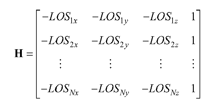
- In an embodiment, and at a
block 320, theprocessor 16 determines an error state covariance matrix P used for a solution separation process described hereinafter. The error covariance matrix P may be determined as a result of a recursive Kalman Filter process illustrated and described in greater detail with reference toFIG. 4 . Note that

- Referring now to
FIG. 4 , at ablock 410, theprocessor 16 computes the Kalman Gain as follows:
where Rk represents the Measurement Noise Covariance matrix. - At a
block 420, theprocessor 16 computes the current estimate of the error state based on the current measurements according to the following:
where Δzk represents the current measurements. Note that

- At a
block 430, theprocessor 16 computes the estimation error covariance matrix as follows:
- At a
block 440, theprocessor 16 projects the estimate of the error state ahead to the next time step as follows:
where Φ k represents the state transition matrix - At a
block 450, theprocessor 16 computes the prediction error covariance matrix (this represents the P matrix used for solution separation):
where Qk represents the system (also referred to as process) noise covariance matrix. - After completing
block 450, the process 300 ofFIG. 3 continues to ablock 330. Alternatively, the process illustrated inFIG. 4 returns to block 410 to repeat the above-described steps. - Referring back to
FIG. 3 , at ablock 330, theprocessor 16 performs a solution separation process. Referring now toFIG. 5 , at ablock 510, theprocessor 16 calculates a discriminator between main solution (subscript 0) and sub-solution j according to the following:

- At a
block 520, theprocessor 16 calculates a detection threshold according to the following:
- If the discriminator exceeds the threshold for any main/sub-solution combination, a satellite failure exists.
- At a
block 530, theprocessor 16 calculates the horizontal and vertical integrity for main least-squares solution according to the following:

- And similarly for vertical integrity:

- In an embodiment, HVPL and VVPL are based on the max values for all main/sub-solution combinations. Note that

block 450 discussed above. - Referring back to
FIG. 3 , at ablock 340, theprocessor 16 calculates track angle, and flight path angle integrity values for hybrid solution. - The hybrid North Velocity, East Velocity, and Ground Speed Integrity are all represented by HVPL calculated above. VVPL represents the hybrid integrity on the vertical velocity.
- Track Angle and Flight Path Angle integrity values are defined as follows:


where
- While a preferred embodiment of the invention has been illustrated and described, as noted above, many changes can be made without departing from the spirit and scope of the invention. Accordingly, the scope of the invention is not limited by the disclosure of the preferred embodiment. Instead, the invention should be determined entirely by reference to the claims that follow.
Claims (10)
- A navigation system (12) for a vehicle having a receiver (14) operable to receive a plurality of signals from a plurality of transmitters, the navigation system comprising:a processor (16); anda memory device (18) having stored thereon machine-readable instructions that, when executed by the processor, enable the processor (16) to:determine a set of pseudo-range measurements derived from the plurality of signals,employing at least one Kalman filter process, determine from the measurements an error covariance matrix for a main navigation solution including associated data characterizing at least one velocity state of the vehicle, andusing a solution separation technique, determine at least one protection level value based on the error covariance matrix.
- The system (12) of claim 1 wherein the instructions further enable the processor (16) to determine a set of error estimates corresponding to delta pseudo-range measurements derived from the plurality of signals.
- The system (12) of claim 1 wherein the instructions further enable the processor (16) to determine an error covariance matrix for at least one navigation sub-solution.
- The system (12) of claim 3 wherein determining at least one protection level value comprises determining a plurality of solution separation parameters, each solution separation parameter being based on statistics of a separation between the main navigation solution and a respective navigation sub-solution.
- The system (12) of claim 4 wherein determining at least one protection level value further comprises determining an error bound for the main navigation solution based on at least one of the solution separation parameters.
- The system (12) of claim 4 wherein determining at least one protection level value further comprises determining each solution separation parameter from a respective covariance matrix describing the statistics of the separation between the main navigation solution and the respective navigation sub-solution.
- The system (12) of claim 1 wherein the at least one protection level value comprises a vertical-velocity integrity value.
- The system (12) of claim 1 wherein the at least one protection level value comprises a flight-path-angle integrity value.
- The system (12) of claim 1 wherein the at least one protection level value comprises a track-angle integrity value.
- A navigation system (12) for a vehicle having a receiver (14) operable to receive a plurality of signals from a plurality of transmitters, the navigation system comprising:a processor (16); anda memory device (18) having stored thereon machine-readable instructions that, when executed by the processor, enable the processor (16) to:determine from the plurality of signals an error covariance matrix for a main navigation solution,determine from the matrix a set of values corresponding to horizontal and vertical velocity states of the vehicle, andbased on said set of values, determine at least one protection level value associated with said velocity states.
Applications Claiming Priority (1)
| Application Number | Priority Date | Filing Date | Title |
|---|---|---|---|
| US12/014,631 US20090182494A1 (en) | 2008-01-15 | 2008-01-15 | Navigation system with apparatus for detecting accuracy failures |
Publications (1)
| Publication Number | Publication Date |
|---|---|
| EP2081043A2 true EP2081043A2 (en) | 2009-07-22 |
Family
ID=40668200
Family Applications (1)
| Application Number | Title | Priority Date | Filing Date |
|---|---|---|---|
| EP09150448A Withdrawn EP2081043A2 (en) | 2008-01-15 | 2009-01-13 | Navigation system with apparatus for detecting accuracy failures |
Country Status (2)
| Country | Link |
|---|---|
| US (1) | US20090182494A1 (en) |
| EP (1) | EP2081043A2 (en) |
Cited By (3)
| Publication number | Priority date | Publication date | Assignee | Title |
|---|---|---|---|---|
| WO2011026961A1 (en) | 2009-09-07 | 2011-03-10 | Sagem Defense Securite | Method and system for determining protection limits with integrated extrapolation over a given time horizon |
| CN104019818A (en) * | 2014-06-19 | 2014-09-03 | 北京理工大学 | Layout optimization method of planet navigation orbiter based on prediction track |
| US11320540B2 (en) | 2019-04-10 | 2022-05-03 | Honeywell International Inc. | Integrity monitoring of primary and derived parameters |
Families Citing this family (9)
| Publication number | Priority date | Publication date | Assignee | Title |
|---|---|---|---|---|
| US8014948B2 (en) * | 2007-12-07 | 2011-09-06 | Honeywell International Inc. | Navigation system with apparatus for detecting accuracy failures |
| US20090182493A1 (en) * | 2008-01-15 | 2009-07-16 | Honeywell International, Inc. | Navigation system with apparatus for detecting accuracy failures |
| US20090182495A1 (en) * | 2008-01-15 | 2009-07-16 | Honeywell International, Inc. | Navigation system with apparatus for detecting accuracy failures |
| FR2947901B1 (en) * | 2009-07-10 | 2012-03-23 | Sagem Defense Securite | METHOD FOR DETERMINING BEARER NAVIGATION PARAMETERS AND HYBRIDIZATION DEVICE |
| CN101949702B (en) * | 2010-07-28 | 2013-04-03 | 北京泰豪联星技术有限公司 | Quick self-testing method for GNSS PVT quality by using MEMS accelerometer |
| US9341718B2 (en) | 2012-09-07 | 2016-05-17 | Honeywell International Inc. | Method and system for providing integrity for hybrid attitude and true heading |
| US9547086B2 (en) * | 2013-03-26 | 2017-01-17 | Honeywell International Inc. | Selected aspects of advanced receiver autonomous integrity monitoring application to kalman filter based navigation filter |
| US9784844B2 (en) | 2013-11-27 | 2017-10-10 | Honeywell International Inc. | Architectures for high integrity multi-constellation solution separation |
| CN111795708B (en) * | 2020-06-16 | 2022-05-06 | 湖南跨线桥航天科技有限公司 | Self-adaptive initial alignment method of land inertial navigation system under base shaking condition |
Family Cites Families (53)
| Publication number | Priority date | Publication date | Assignee | Title |
|---|---|---|---|---|
| NO148037C (en) * | 1977-12-22 | 1983-08-24 | Unilever Nv | LIQUID DETERGENT MIXTURE. |
| JPS54159416A (en) * | 1978-06-07 | 1979-12-17 | Lion Corp | Liquid detergent composition |
| US6239740B1 (en) * | 1991-04-15 | 2001-05-29 | The United States Of America As Represented By The Secretary Of The Navy | Efficient data association with multivariate Gaussian distributed states |
| US5512903A (en) * | 1994-05-23 | 1996-04-30 | Honeywell Inc. | Integrity limit apparatus and method |
| US5436632A (en) * | 1994-06-02 | 1995-07-25 | Trimble Navigation Limited | Integrity monitoring of differential satellite positioning system signals |
| US5931889A (en) * | 1995-01-24 | 1999-08-03 | Massachusetts Institute Of Technology | Clock-aided satellite navigation receiver system for monitoring the integrity of satellite signals |
| US5906665A (en) * | 1995-09-26 | 1999-05-25 | General Technology Applications, Inc. | High molecular weight fuel additive |
| US5808581A (en) * | 1995-12-07 | 1998-09-15 | Trimble Navigation Limited | Fault detection and exclusion method for navigation satellite receivers |
| FR2749665B1 (en) * | 1996-06-07 | 1998-09-11 | Sextant Avionique | SATELLITE SIGNAL RECEIVER WITH SPEED CALCULATION INTEGRITY CONTROL |
| US5786773A (en) * | 1996-10-02 | 1998-07-28 | The Boeing Company | Local-area augmentation system for satellite navigation precision-approach system |
| US6204806B1 (en) * | 1999-02-26 | 2001-03-20 | Rockwell Collins, Inc. | Method of enhancing receiver autonomous GPS navigation integrity monitoring and GPS receiver implementing the same |
| US6205377B1 (en) * | 1999-04-27 | 2001-03-20 | Trimble Navigation Ltd | Method for navigation of moving platform by using satellite data supplemented by satellite-calibrated baro data |
| US6281836B1 (en) * | 1999-05-21 | 2001-08-28 | Trimble Navigation Ltd | Horizontal/vertical protection level adjustment scheme for RAIM with baro measurements |
| US6760663B2 (en) * | 1999-09-14 | 2004-07-06 | Honeywell International Inc. | Solution separation method and apparatus for ground-augmented global positioning system |
| US6134484A (en) * | 2000-01-28 | 2000-10-17 | Motorola, Inc. | Method and apparatus for maintaining the integrity of spacecraft based time and position using GPS |
| US6317688B1 (en) * | 2000-01-31 | 2001-11-13 | Rockwell Collins | Method and apparatus for achieving sole means navigation from global navigation satelite systems |
| US6407701B2 (en) * | 2000-03-24 | 2002-06-18 | Clarion Co., Ltd. | GPS receiver capable of calculating accurate 2DRMS |
| US6570531B1 (en) * | 2000-04-27 | 2003-05-27 | Rockwell Collins, Inc. | Satellite navigation receiver designed for compatibility with aircraft automatic landing systems |
| US6466846B2 (en) * | 2000-07-10 | 2002-10-15 | United Parcel Service Of America, Inc. | Method, apparatus, system, and computer software program product for determining position integrity in a system having a global navigation satellite system (GNSS) component |
| US6691066B1 (en) * | 2000-08-28 | 2004-02-10 | Sirf Technology, Inc. | Measurement fault detection |
| US6711478B2 (en) * | 2000-12-15 | 2004-03-23 | Garmin At, Inc. | Receiver-autonomous vertical integrity monitoring |
| US6424914B1 (en) * | 2000-12-26 | 2002-07-23 | American Gnc Corporation | Fully-coupled vehicle positioning method and system thereof |
| US6577952B2 (en) * | 2001-01-08 | 2003-06-10 | Motorola, Inc. | Position and heading error-correction method and apparatus for vehicle navigation systems |
| US6769663B2 (en) * | 2001-06-25 | 2004-08-03 | Meadow Burke Products | Void forming and anchor positioning apparatus and method for concrete structures |
| US6757579B1 (en) * | 2001-09-13 | 2004-06-29 | Advanced Micro Devices, Inc. | Kalman filter state estimation for a manufacturing system |
| FR2830320B1 (en) * | 2001-09-28 | 2003-11-28 | Thales Sa | HYBRYDAL INERTIAL NAVIGATION CENTER WITH IMPROVED INTEGRITY |
| US6639549B2 (en) * | 2001-12-20 | 2003-10-28 | Honeywell International Inc. | Fault detection and exclusion for global position systems |
| US6944540B2 (en) * | 2002-03-28 | 2005-09-13 | Motorola, Inc. | Time determination in satellite positioning system receivers and methods therefor |
| US6860023B2 (en) * | 2002-12-30 | 2005-03-01 | Honeywell International Inc. | Methods and apparatus for automatic magnetic compensation |
| US6781542B2 (en) * | 2003-01-13 | 2004-08-24 | The Boeing Company | Method and system for estimating ionospheric delay using a single frequency or dual frequency GPS signal |
| US6847893B1 (en) * | 2003-01-22 | 2005-01-25 | Trimble Navigation, Ltd | Horizontal/vertical exclusion level determination scheme for RAIM fault detection and exclusion implementation |
| US7170447B2 (en) * | 2003-02-14 | 2007-01-30 | Qualcomm Incorporated | Method and apparatus for processing navigation data in position determination |
| US7027918B2 (en) * | 2003-04-07 | 2006-04-11 | Novariant, Inc. | Satellite navigation system using multiple antennas |
| US6856905B2 (en) * | 2003-04-29 | 2005-02-15 | Garmin At, Inc. | Systems and methods for fault detection and exclusion in navigational systems |
| US6798377B1 (en) * | 2003-05-31 | 2004-09-28 | Trimble Navigation, Ltd. | Adaptive threshold logic implementation for RAIM fault detection and exclusion function |
| US7148843B2 (en) * | 2003-07-02 | 2006-12-12 | Thales North America, Inc. | Enhanced real time kinematics determination method and apparatus |
| US7463956B2 (en) * | 2003-07-03 | 2008-12-09 | The Boeing Company | Constant vertical state maintaining cueing system |
| US7219013B1 (en) * | 2003-07-31 | 2007-05-15 | Rockwell Collins, Inc. | Method and system for fault detection and exclusion for multi-sensor navigation systems |
| US7400292B2 (en) * | 2003-11-04 | 2008-07-15 | The Boeing Company | GPS Navigation system with integrity and reliability monitoring channels |
| US20060047413A1 (en) * | 2003-12-02 | 2006-03-02 | Lopez Nestor Z | GNSS navigation solution integrity in non-controlled environments |
| US6861979B1 (en) * | 2004-01-16 | 2005-03-01 | Topcon Gps, Llc | Method and apparatus for detecting anomalous measurements in a satellite navigation receiver |
| FR2866423B1 (en) * | 2004-02-13 | 2006-05-05 | Thales Sa | DEVICE FOR MONITORING THE INTEGRITY OF THE INFORMATION DELIVERED BY AN INS / GNSS HYBRID SYSTEM |
| US7095369B1 (en) * | 2004-06-15 | 2006-08-22 | Lockheed Martin Corporation | Phase step alert signal for GPS integrity monitoring |
| US7365678B2 (en) * | 2004-12-16 | 2008-04-29 | Raytheon Company | Determining usability of a navigation augmentation system |
| US7783425B1 (en) * | 2005-06-29 | 2010-08-24 | Rockwell Collins, Inc. | Integrity-optimized receiver autonomous integrity monitoring (RAIM) |
| US7860651B2 (en) * | 2005-08-30 | 2010-12-28 | Honeywell International Inc. | Enhanced inertial system performance |
| US7688261B2 (en) * | 2006-03-15 | 2010-03-30 | The Boeing Company | Global position system (GPS) user receiver and geometric surface processing for all-in-view coherent GPS signal PRN codes acquisition and navigation solution |
| US7587296B2 (en) * | 2006-05-07 | 2009-09-08 | Applied Materials, Inc. | Adaptive multivariate fault detection |
| FR2906893B1 (en) * | 2006-10-06 | 2009-01-16 | Thales Sa | METHOD AND DEVICE FOR MONITORING THE INTEGRITY OF INFORMATION DELIVERED BY AN INS / GNSS HYBRID SYSTEM |
| JP2010538243A (en) * | 2007-06-08 | 2010-12-09 | クゥアルコム・インコーポレイテッド | GNSS positioning using pressure sensor |
| US8014948B2 (en) * | 2007-12-07 | 2011-09-06 | Honeywell International Inc. | Navigation system with apparatus for detecting accuracy failures |
| US20090182493A1 (en) * | 2008-01-15 | 2009-07-16 | Honeywell International, Inc. | Navigation system with apparatus for detecting accuracy failures |
| US20090182495A1 (en) * | 2008-01-15 | 2009-07-16 | Honeywell International, Inc. | Navigation system with apparatus for detecting accuracy failures |
-
2008
- 2008-01-15 US US12/014,631 patent/US20090182494A1/en not_active Abandoned
-
2009
- 2009-01-13 EP EP09150448A patent/EP2081043A2/en not_active Withdrawn
Cited By (9)
| Publication number | Priority date | Publication date | Assignee | Title |
|---|---|---|---|---|
| WO2011026961A1 (en) | 2009-09-07 | 2011-03-10 | Sagem Defense Securite | Method and system for determining protection limits with integrated extrapolation over a given time horizon |
| FR2949852A1 (en) * | 2009-09-07 | 2011-03-11 | Sagem Defense Securite | METHOD AND SYSTEM FOR DETERMINING PROTECTION LIMITS WITH INTEGRATED EXTRAPOLATION ON A TEMPORAL TIME HORIZON |
| CN102597703A (en) * | 2009-09-07 | 2012-07-18 | 萨热姆防务安全公司 | Method and system for determining protection limits with integrated extrapolation over a given time horizon |
| US8843243B2 (en) | 2009-09-07 | 2014-09-23 | Sagem Defense Securite | Method and system for determining protection limits with integrated extrapolation over a given time horizon |
| CN102597703B (en) * | 2009-09-07 | 2015-03-25 | 萨热姆防务安全公司 | Method and system for determining protection limits with integrated extrapolation over a given time horizon |
| RU2552160C2 (en) * | 2009-09-07 | 2015-06-10 | Сагем Дефенс Секьюрите | Method and system for determining protection limits with integrated extrapolation over given time horizon |
| CN104019818A (en) * | 2014-06-19 | 2014-09-03 | 北京理工大学 | Layout optimization method of planet navigation orbiter based on prediction track |
| CN104019818B (en) * | 2014-06-19 | 2016-08-24 | 北京理工大学 | A kind of planet based on prediction locus navigation orbiter, orbital vehicle layout optimization method |
| US11320540B2 (en) | 2019-04-10 | 2022-05-03 | Honeywell International Inc. | Integrity monitoring of primary and derived parameters |
Also Published As
| Publication number | Publication date |
|---|---|
| US20090182494A1 (en) | 2009-07-16 |
Similar Documents
| Publication | Publication Date | Title |
|---|---|---|
| EP2081043A2 (en) | Navigation system with apparatus for detecting accuracy failures | |
| EP2081042A2 (en) | Navigation system with apparatus for detecting accuracy failures | |
| EP2081044A2 (en) | Navigation system with apparatus for detecting accuracy failures | |
| EP2068165B1 (en) | Navigation system with apparatus for detecting accuracy failures | |
| EP3598177B1 (en) | Selected aspects of advanced receiver autonomous integrity monitoring application to kalman filter based navigation filter | |
| US5883595A (en) | Method and apparatus for mitigating multipath effects and smoothing groundtracks in a GPS receiver | |
| EP2706379B1 (en) | Method and system for providing integrity for hybrid attitude and true heading | |
| US11143765B2 (en) | Reducing bias impact on GNSS integrity | |
| US7724184B2 (en) | System and method for detecting false navigation signals | |
| US6760663B2 (en) | Solution separation method and apparatus for ground-augmented global positioning system | |
| US6711478B2 (en) | Receiver-autonomous vertical integrity monitoring | |
| CN101395443B (en) | Hybrid positioning method and device | |
| US8909471B1 (en) | Voting system and method using doppler aided navigation | |
| US6845304B1 (en) | Method of and system for deriving inertial-aided deviations for autoland systems during GPS signal interruptions | |
| US6298316B1 (en) | Failure detection system | |
| EP3722834B1 (en) | Integrity monitoring of primary and derived parameters | |
| JP5566598B2 (en) | Navigation system comprising a device for detecting inaccuracy | |
| Han et al. | GNSS/IMU tightly coupled scheme with weighting and FDE for rail applications | |
| US9562788B1 (en) | System and method for doppler aided navigation using weather radar | |
| CA2645697C (en) | Navigation system with apparatus for detecting accuracy failures | |
| EP1970723A1 (en) | Method for the computation of improved SBAS protection levels valid in non-controlled environments | |
| RU2389042C2 (en) | Method of determining protective limit around position of moving body calculated from satellite signals | |
| Bhatti | An improved sensor level integrity algorithm for GPS/INS integrated system | |
| Chan et al. | High-Integrity GPS/INS Integrated Navigation with Error Detection and Application to LAAS | |
| KR20220103553A (en) | Apparatus and method for screening doppler measurement fault, and apparatus and method for detecting gnss measurement fault |
Legal Events
| Date | Code | Title | Description |
|---|---|---|---|
| PUAI | Public reference made under article 153(3) epc to a published international application that has entered the european phase |
Free format text: ORIGINAL CODE: 0009012 |
|
| 17P | Request for examination filed |
Effective date: 20090113 |
|
| AK | Designated contracting states |
Kind code of ref document: A2 Designated state(s): AT BE BG CH CY CZ DE DK EE ES FI FR GB GR HR HU IE IS IT LI LT LU LV MC MK MT NL NO PL PT RO SE SI SK TR |
|
| AX | Request for extension of the european patent |
Extension state: AL BA RS |
|
| STAA | Information on the status of an ep patent application or granted ep patent |
Free format text: STATUS: THE APPLICATION HAS BEEN WITHDRAWN |
|
| 18W | Application withdrawn |
Effective date: 20120717 |