EP2081011A1 - Biosensor device - Google Patents
Biosensor device Download PDFInfo
- Publication number
- EP2081011A1 EP2081011A1 EP07807764A EP07807764A EP2081011A1 EP 2081011 A1 EP2081011 A1 EP 2081011A1 EP 07807764 A EP07807764 A EP 07807764A EP 07807764 A EP07807764 A EP 07807764A EP 2081011 A1 EP2081011 A1 EP 2081011A1
- Authority
- EP
- European Patent Office
- Prior art keywords
- biosensor
- light beam
- spectrometers
- detection apparatus
- measurement
- Prior art date
- Legal status (The legal status is an assumption and is not a legal conclusion. Google has not performed a legal analysis and makes no representation as to the accuracy of the status listed.)
- Withdrawn
Links
- 238000005259 measurement Methods 0.000 claims abstract description 56
- 238000001514 detection method Methods 0.000 claims abstract description 45
- 230000003287 optical effect Effects 0.000 claims abstract description 31
- 230000003595 spectral effect Effects 0.000 claims abstract description 18
- 238000009826 distribution Methods 0.000 claims abstract description 17
- 239000013307 optical fiber Substances 0.000 claims description 15
- 239000000758 substrate Substances 0.000 claims description 6
- 238000012545 processing Methods 0.000 abstract description 7
- 230000003993 interaction Effects 0.000 description 15
- 150000001875 compounds Chemical class 0.000 description 11
- 238000005286 illumination Methods 0.000 description 8
- 238000010586 diagram Methods 0.000 description 4
- 239000000463 material Substances 0.000 description 4
- 102000004169 proteins and genes Human genes 0.000 description 4
- 108090000623 proteins and genes Proteins 0.000 description 4
- 238000011002 quantification Methods 0.000 description 4
- 238000006243 chemical reaction Methods 0.000 description 3
- 238000012986 modification Methods 0.000 description 3
- 230000004048 modification Effects 0.000 description 3
- 239000000126 substance Substances 0.000 description 2
- 230000015556 catabolic process Effects 0.000 description 1
- 238000006731 degradation reaction Methods 0.000 description 1
- 239000003814 drug Substances 0.000 description 1
- 230000000694 effects Effects 0.000 description 1
- 238000000034 method Methods 0.000 description 1
- 230000001902 propagating effect Effects 0.000 description 1
- 230000003252 repetitive effect Effects 0.000 description 1
Images

Classifications
-
- G—PHYSICS
- G01—MEASURING; TESTING
- G01N—INVESTIGATING OR ANALYSING MATERIALS BY DETERMINING THEIR CHEMICAL OR PHYSICAL PROPERTIES
- G01N21/00—Investigating or analysing materials by the use of optical means, i.e. using sub-millimetre waves, infrared, visible or ultraviolet light
- G01N21/17—Systems in which incident light is modified in accordance with the properties of the material investigated
- G01N21/25—Colour; Spectral properties, i.e. comparison of effect of material on the light at two or more different wavelengths or wavelength bands
- G01N21/251—Colorimeters; Construction thereof
- G01N21/253—Colorimeters; Construction thereof for batch operation, i.e. multisample apparatus
-
- G—PHYSICS
- G01—MEASURING; TESTING
- G01N—INVESTIGATING OR ANALYSING MATERIALS BY DETERMINING THEIR CHEMICAL OR PHYSICAL PROPERTIES
- G01N2201/00—Features of devices classified in G01N21/00
- G01N2201/08—Optical fibres; light guides
- G01N2201/0826—Fibre array at source, distributing
-
- G—PHYSICS
- G01—MEASURING; TESTING
- G01N—INVESTIGATING OR ANALYSING MATERIALS BY DETERMINING THEIR CHEMICAL OR PHYSICAL PROPERTIES
- G01N2201/00—Features of devices classified in G01N21/00
- G01N2201/08—Optical fibres; light guides
- G01N2201/0833—Fibre array at detector, resolving
Definitions
- the present invention generally relates to a biosensor detection apparatus, and more particularly to a biosensor detection apparatus for obtaining a spectral intensity distribution of a light beam reflected from a biosensor.
- a biosensor which allows quantification of the interaction between a specific protein and each of different compounds simultaneously.
- a biosensor includes, for example, a substrate layer, a two-dimensional grating layer stacked on the substrate layer, a specific bonding substance immobilized on the surface of the two-dimensional grating layer, and the like.
- the cross-section of the grating layer has aperiodic repetitive pattern, such as rectangular waveform shape, sine waveform shape, or the like.
- a microtiter plate having a multitude of openings is stacked on the biosensor, and each region on the biosensor def ined by each opening of the microtiter plate is used as a measurement region in which the interaction between compounds (for example, between the specific protein and compound described above) takes place. Then, white light is emitted to the measurement region and a measurement target light beam reflected from the measurement region illuminated with the white light is spectrally analyzed, whereby the state of interaction between the compounds is quantified.
- the peak wavelength in the spectral intensity distribution of the light beam reflected from the measurement region shifts according to the state of interaction between the compounds, so that the state of interaction between the compounds can be quantified by measuring the shift amount of the peak wavelength.
- a biosensor detection apparatus having 8 measurement channels is known as described, for example, in U.S. Patent No. 7,023,544 .
- the biosensor detection apparatus includes a biosensor reaction vessel having measurement regions arranged in 8 rows by 12 columns, and the interaction between compounds taking place in each measurement region is quantified.
- 8 measurement regions in the 1 st column of each row of the biosensor reaction vessel are measured simultaneously through the 8 measurement channels, and then the measurement is sequentially performed for the 2 nd to 12 th columns using the 8 measurement channels.
- the biosensor detection apparatus described above includes, for each measurement channel, a spectral measurement unit having an illumination optical fiber for emitting white light, i.e., illumination light, to each measurement region, a detection optical fiber for guiding each light beam reflected from each measurement region illuminated with the white light, a spectrometer for spectrally separating the light beam outputted from the detection optical fiber, and an optical receiver for measuring the spectral intensity distribution of the spectrally separated light beam.
- the measurement using the 8 channels (using 8 spectral measurement units) is sequentially performed from the 1 st to 12 th columns, whereby all of the measurement regions of the biosensor are measured.
- the relative movement between the biosensor and spectral measurement units for sequentially measuring the 1 st to 12 th columns is implemented mechanically.
- the present invention has been developed in view of the circumstances described above, and it is an object of the present invention to provide a biosensor detection apparatus capable of providing increased processing power for the measurement while preventing structural complication and size increase in the apparatus.
- a biosensor detection apparatus of the present invention is an apparatus including:
- the one or more spectrometers may be constituted by one diffraction grating.
- the diffraction grating is also referred to as simply "grating".
- the one or more optical receivers may be constituted by one substrate on which a multitude of light receiving elements is disposed two-dimensionally.
- the biosensor detection apparatus may further includes detection optical fibers, each for separately receiving each reflected light beam at one end and guiding the light beam to the one or more spectrometers.
- the apparatus may include one spectrometer and one optical receiver described above.
- the apparatus includes one or more spectrometers configured to spectrally separate each light beam reflected from each of a plurality of measurement regions defined on a biosensor simultaneously, and one or more optical receivers configured to receive each light beam spectrally separated by the one or more spectrometers simultaneously and to obtain a spectral intensity distribution of each light beam separately.
- each light beam reflected from each of a plurality of measurement regions on the biosensor is spectrally separated simultaneously by the one or more spectrometers, and each light beam spectrally separated by the one or more spectrometers is received simultaneously by the one or more optical receivers and a spectral intensity distribution of each light beam is obtained separately.
- This allows the interaction between compounds occurred in each of all measurement regions to be quantified without relatively moving the spectrometers and biosensor as in the conventional biosensor detection apparatus.
- This may eliminate the mechanism employed in the conventional biosensor detection apparatus for relatively moving the spectral measurement unit constituted by spectrometers and optical receivers and the biosensor. Consequently, the time required for the relative movement may also be eliminated, so that the number of measurement regions processed per unit time may be increased.
- the biosensor detection apparatus described above may provide increased processing power for the measurement while preventing structural complication and size increase in the apparatus.
- the one or more spectrometers are constituted by one diffraction grating, the structural complication and size increase may be definitely prevented.
- the one or more optical receivers are constituted by one substrate on which a multitude of light receiving elements is disposed two-dimensionally, the structural complication and size increase may be definitely prevented.
- each light beam reflected from each measurement region may be reliably guided to the spectrometers, and further may prevent the degradation of S/N ratio due to mixing of light beams reflected from each measurement region, which allows more accurate quantification.
- the apparatus includes one spectrometer and one optical receiver described above, the structural complication and size increase may be further prevented.
- FIG. 1 is a conceptual diagram of a biosensor detection apparatus according to an embodiment of the present invention, illustrating the schematic configuration thereof.
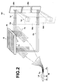
- Figure 2 is a conceptual diagram of a modification example of the biosensor detection apparatus described above, illustrating the schematic configuration thereof.
- Biosensor detection apparatus 100 includes one spectrometer 20 configured to spectrally separate each of light beams Lr1, Lr2, ----- (also, collectively referred to as "light beams Lr”) reflected from each of measurement regions R1, R2, ----- (also, collectively referred to as “measurement regions R”) defined on biosensor 10 simultaneously, and one optical receiver 30 configured to receive each of light beams Ls1, Ls2, ----- (also, collectively referred to as "light beams Ls”) simultaneously and to obtain a spectral intensity distribution of each light beam separately.
- Biosensor detection apparatus 100 further includes, between biosensor 10 and spectrometer 20, detection optical fibers Fk1, Fk2, ----- (also, collectively referred to as “detection optical fibers Fk”), each for separately receiving each of light beams Lr1, Lr2, ----- reflected from lower surface 11 of each of measurement regions R1, R2, ----- illuminated with white light Lw at one end and guiding each of light beams Lr1, Lr2, ----- to spectrometer 2 0, and collimator lenses Cp1, Cp2, ----- (also, collectively referred to as “collimator lenses Cp”), each provided for each of detection optical fibers Fk1, Fk2, ----- for collimating and outputting each of light beams Lr1, Lr2, ----- outputted from each of detection optical fibers Fk1, Fk2, ----- to a predetermined area of spectrometer 20.
- detection optical fibers Fk1, Fk2, ----- also, collectively referred to as "detection optical fibers Fk"
- Biosensor detection apparatus 100 further includes illumination system 50 having light source 51 for emitting white light Lw, i.e., illumination light, condenser lens 52 for condensing white light Lw emitted from light source 51, and illumination optical fibers Fs1, Fs2, -----, each for illuminating each of measurement regions R1, R2, ----- from the side of lower surface 11 by receiving white light Lw condensed by condenser lens 52 at first end Ta, propagating white light Lw to second end Tb, and emitting white light Lw from second end Tb toward each of measurement regions R1, R2, -----.
- illumination system 50 having light source 51 for emitting white light Lw, i.e., illumination light, condenser lens 52 for condensing white light Lw emitted from light source 51, and illumination optical fibers Fs1, Fs2, -----, each for illuminating each of measurement regions R1, R2, ----- from the side of lower surface 11 by receiving white light Lw condensed by condenser lens 52 at first end Ta
- spectrometer 20 is an elongated diffraction grating, and spectrally separates each of a plurality of inputted light beams simultaneously and outputs each of spectrally separated light beams to a different area of optical receiver 30.
- spectrometer 20 is not limited to the diffraction grating type and the other type, such as prism type or the like may be used.
- two or more spectrometers 20a, 20b may be provided, as described later, instead of one spectrometer 20.
- optical receiver 30 an optical receiver having a multitude of light receiving elements disposed two-dimensionally on one substrate may be used.
- a two-dimensional CCD array is used as optical receiver 30.
- Optical receiver 30 receives each light beam spectrally separated by spectrometer 20 and obtains a light amount distribution of the light beam from the position of each light receiving element and a light amount received by each light receiving element. This light amount distribution corresponds to the spectral intensity distribution. That is, the position of each light receiving element that receives the spectrally separated light beam corresponds to each wavelength and the light amount received by each light receiving element represents the light intensity of each wavelength, so that the spectral intensity distribution of the spectrally separated light beam can be obtained from the light amount distribution.
- optical receivers 30a, 30b may be provided, as described later, instead of one optical receiver 30.
- Biosensor 10 basically includes a one-dimensional grating layer with a high refractive index material, a low refractive index material layer, having a lower refractive index than that of the high refractive index material, for supporting the one-dimensional grating, and one or more specific bonding substances immobilized on the surface of the one-dimensional grating on the side opposite to the low refractive index material layer.
- biosensor 10 has 96 measurement regions in total, arranged in 8 rows by 12 columns, that is, biosensor 10 has a standardized 96-well format, but the other format, such as 384-well format, 1156-well format, or the like may be used.
- Each of the measurement regions of biosensor 10 may be defined by any known method, such as stacking a microtiter plate having a multitude of openings on biosensor 10.
- Biosensor 10 has an identical structure to that of the biosensor described in U.S. Patent No. 7,023,544 .
- Biosensor detection apparatus 100 includes 96 illumination optical fibers Fs, 96 detection optical fibers Fk, and 96 collimator lenses Cp.
- the elongated diffraction grating, spectrometer 20 has 96 different areas thereon for spectrally separating different light beams, and spectrally separated 96 light beams Ls1, Ls2,simultaneously by spectrometer 20 are received at 96 different areas on the two-dimensional CCD array, i.e., optical receiver 30, simultaneously.
- Each of light beams Lr reflected from each of measurement regions R illuminated with white light Lw is inputted to spectrometer 20 simultaneously through each of detection optical fibers Fk and each of collimator lenses Cp.
- Each of light beams Ls spectrally separated by spectrometer 20 is inputted to optical receiver simultaneously and the spectral intensity distribution of each of light beams Ls is obtained by optical receiver 30.
- the peak wavelength in the spectral intensity distribution of each light beam reflected from each of measurement regions R shifts according to the state of interaction, so that the interaction may be quantified by measuring the shift amount of the peak wavelength.
- the processing power for the measurement of the apparatus may be increased while preventing structural complication and size increase in the apparatus.
- Figure 2 illustrates a modification example of biosensor detection apparatus 100.
- components identical to those in Figure 1 are given the same reference symbols and will not be elaborated upon further here.
- Biosensor detection apparatus 101 shown in Figure 2 includes two or more spectrometers 20a, 20b, -----, instead of one spectrometer 20, and light beams Lr reflected from respective measurement regions R are spectrally separated simultaneously using two or more spectrometers 20a, 20b, -----. Further, biosensor detection apparatus 101 includes two or more optical receivers 30a, 30b, -----, instead of one optical receiver 30, and light beams Ls spectrally separated by spectrometers 20a, 20b, ----- are received by two or more optical receivers 30a, 30b, ----- simultaneously to obtain spectral intensity distributions of light beams Ls individually. Other structures and operations are identical to those of biosensor detection apparatus 100.
- a configuration may be adopted in which light beams Ls spectrally separated by one spectrometer 20 shown in Figure 1 are received simultaneously by two or more optical receivers 30a, 30b, -----, or light beams Ls spectrally separated by two or more spectrometers 20a, 20b, ----- shown in Figure 2 are received simultaneously by one optical receiver 30 shown in Figure 1 .
Landscapes
- Physics & Mathematics (AREA)
- Spectroscopy & Molecular Physics (AREA)
- Health & Medical Sciences (AREA)
- Life Sciences & Earth Sciences (AREA)
- Chemical & Material Sciences (AREA)
- Analytical Chemistry (AREA)
- Biochemistry (AREA)
- General Health & Medical Sciences (AREA)
- General Physics & Mathematics (AREA)
- Immunology (AREA)
- Pathology (AREA)
- Investigating Or Analysing Materials By Optical Means (AREA)
Abstract
Improving processing power of a biosensor detection apparatus for measurement while preventing structural complication and size increase in the apparatus. Providing one or more spectrometers (20) configured to spectrally separate each light beam (Lr) reflected from each of a plurality of measurement regions defined on a biosensor (10) simultaneously and one or more optical receivers (30) configured to receive each light beam (Ls) spectrally separated by the one or more spectrometers (20) simultaneously, thereby enabling the apparatus to obtain a spectral intensity distribution of each light beam (Ls) separately.
Description
- The present invention generally relates to a biosensor detection apparatus, and more particularly to a biosensor detection apparatus for obtaining a spectral intensity distribution of a light beam reflected from a biosensor.
- Studies have been conducted for investigating the interaction between a specific protein and a compound of candidate medicine. Further, devices for quantitatively measuring the interaction have also been known. As one of the sensors used in such devices, for example, a biosensor is known, which allows quantification of the interaction between a specific protein and each of different compounds simultaneously. Such a biosensor includes, for example, a substrate layer, a two-dimensional grating layer stacked on the substrate layer, a specific bonding substance immobilized on the surface of the two-dimensional grating layer, and the like. The cross-section of the grating layer has aperiodic repetitive pattern, such as rectangular waveform shape, sine waveform shape, or the like.
- A microtiter plate having a multitude of openings is stacked on the biosensor, and each region on the biosensor def ined by each opening of the microtiter plate is used as a measurement region in which the interaction between compounds (for example, between the specific protein and compound described above) takes place. Then, white light is emitted to the measurement region and a measurement target light beam reflected from the measurement region illuminated with the white light is spectrally analyzed, whereby the state of interaction between the compounds is quantified.
- That is, the peak wavelength in the spectral intensity distribution of the light beam reflected from the measurement region shifts according to the state of interaction between the compounds, so that the state of interaction between the compounds can be quantified by measuring the shift amount of the peak wavelength.
- According to the measurement using a biosensor reaction vessel having a multitude of measurement regions defined by stacking the microtiter plate having a multitude of openings described above, it is possible to quantitatively analyze each of several thousands of interactions taking place simultaneously on the biosensor.
- Further, as the device for performing quantification for a multitude of measurement regions described above, a biosensor detection apparatus having 8 measurement channels is known as described, for example, in
U.S. Patent No. 7,023,544 . The biosensor detection apparatus includes a biosensor reaction vessel having measurement regions arranged in 8 rows by 12 columns, and the interaction between compounds taking place in each measurement region is quantified. In the apparatus, 8 measurement regions in the 1st column of each row of the biosensor reaction vessel are measured simultaneously through the 8 measurement channels, and then the measurement is sequentially performed for the 2nd to 12th columns using the 8 measurement channels. - The biosensor detection apparatus described above includes, for each measurement channel, a spectral measurement unit having an illumination optical fiber for emitting white light, i.e., illumination light, to each measurement region, a detection optical fiber for guiding each light beam reflected from each measurement region illuminated with the white light, a spectrometer for spectrally separating the light beam outputted from the detection optical fiber, and an optical receiver for measuring the spectral intensity distribution of the spectrally separated light beam. The measurement using the 8 channels (using 8 spectral measurement units) is sequentially performed from the 1st to 12th columns, whereby all of the measurement regions of the biosensor are measured. The relative movement between the biosensor and spectral measurement units for sequentially measuring the 1st to 12th columns is implemented mechanically.
- In the mean time, with the recent advancement in biotechnology, the demand for shorter quantification time for the interaction between each of a great number of compounds, i.e., enhanced processing power for the quantitative measurement is growing. For example, in order to enhance the processing power of the 8-channel biosensor detection apparatus for the quantitative measurement, it is conceivable to increase the number of channels or channel scanning speed. If the number of channels for the biosensor detection apparatus is increased, however, the number of spectrometers is also increased in proportion to the increased number of channels. When the channel scanning speed is increased, the load on the scanning mechanism is also increased according to the speeding-up level. Therefore, enhancement of processing power for the apparatus will result in complicated structure and increased size.
- The present invention has been developed in view of the circumstances described above, and it is an object of the present invention to provide a biosensor detection apparatus capable of providing increased processing power for the measurement while preventing structural complication and size increase in the apparatus.
- A biosensor detection apparatus of the present invention is an apparatus including:
- one or more spectrometers configured to spectrally separate each light beam reflected from each of a plurality of measurement regions defined on a biosensor simultaneously; and
- one or more optical receivers configured to receive each light beam spectrally separated by the one or more spectrometers simultaneously and to obtain a spectral intensity distribution of each light beam separately.
- The one or more spectrometers may be constituted by one diffraction grating. The diffraction grating is also referred to as simply "grating".
- The one or more optical receivers may be constituted by one substrate on which a multitude of light receiving elements is disposed two-dimensionally.
- The biosensor detection apparatus may further includes detection optical fibers, each for separately receiving each reflected light beam at one end and guiding the light beam to the one or more spectrometers.
- The apparatus may include one spectrometer and one optical receiver described above.
- According to the biosensor detection apparatus of the present invention, the apparatus includes one or more spectrometers configured to spectrally separate each light beam reflected from each of a plurality of measurement regions defined on a biosensor simultaneously, and one or more optical receivers configured to receive each light beam spectrally separated by the one or more spectrometers simultaneously and to obtain a spectral intensity distribution of each light beam separately. This allows the measurement without requiring separate spectrometers, each corresponding to each measurement region and separate optical receivers, each corresponding to each spectrometer as in the conventional biosensor detection apparatus, whereby the number of spectrometers and the number of optical receivers to be provided in the apparatus may be reduced.
- Further, each light beam reflected from each of a plurality of measurement regions on the biosensor is spectrally separated simultaneously by the one or more spectrometers, and each light beam spectrally separated by the one or more spectrometers is received simultaneously by the one or more optical receivers and a spectral intensity distribution of each light beam is obtained separately. This allows the interaction between compounds occurred in each of all measurement regions to be quantified without relatively moving the spectrometers and biosensor as in the conventional biosensor detection apparatus. This may eliminate the mechanism employed in the conventional biosensor detection apparatus for relatively moving the spectral measurement unit constituted by spectrometers and optical receivers and the biosensor. Consequently, the time required for the relative movement may also be eliminated, so that the number of measurement regions processed per unit time may be increased.
- Because of the advantageous effects described above, the biosensor detection apparatus described above may provide increased processing power for the measurement while preventing structural complication and size increase in the apparatus.
- Further, if the one or more spectrometers are constituted by one diffraction grating, the structural complication and size increase may be definitely prevented.
- Still further, if the one or more optical receivers are constituted by one substrate on which a multitude of light receiving elements is disposed two-dimensionally, the structural complication and size increase may be definitely prevented.
- Further, where the apparatus further includes detection optical fibers, each for separately receiving each reflected light beam at one end and guiding the light beam to the one or more spectrometers, each light beam reflected from each measurement region may be reliably guided to the spectrometers, and further may prevent the degradation of S/N ratio due to mixing of light beams reflected from each measurement region, which allows more accurate quantification.
- Still further, if the apparatus includes one spectrometer and one optical receiver described above, the structural complication and size increase may be further prevented.
-
-
Figure 1 is a conceptual diagram of a biosensor detection apparatus according to an embodiment of the present invention, illustrating the schematic configuration thereof. -
Figure 2 is a conceptual diagram of a modification example of the biosensor detection apparatus according to the embodiment of the present invention, illustrating the schematic configuration thereof. - Hereinafter, embodiments of the present invention will be described with reference to the accompanying drawings.
Figure 1 is a conceptual diagram of a biosensor detection apparatus according to an embodiment of the present invention, illustrating the schematic configuration thereof.Figure 2 is a conceptual diagram of a modification example of the biosensor detection apparatus described above, illustrating the schematic configuration thereof. -
Biosensor detection apparatus 100 according to an embodiment of the present invention shown inFigure 1 includes onespectrometer 20 configured to spectrally separate each of light beams Lr1, Lr2, ----- (also, collectively referred to as "light beams Lr") reflected from each of measurement regions R1, R2, ----- (also, collectively referred to as "measurement regions R") defined onbiosensor 10 simultaneously, and oneoptical receiver 30 configured to receive each of light beams Ls1, Ls2, ----- (also, collectively referred to as "light beams Ls") simultaneously and to obtain a spectral intensity distribution of each light beam separately. -
Biosensor detection apparatus 100 further includes, betweenbiosensor 10 andspectrometer 20, detection optical fibers Fk1, Fk2, ----- (also, collectively referred to as "detection optical fibers Fk"), each for separately receiving each of light beams Lr1, Lr2, ----- reflected fromlower surface 11 of each of measurement regions R1, R2, ----- illuminated with white light Lw at one end and guiding each of light beams Lr1, Lr2, ----- to spectrometer 2 0, and collimator lenses Cp1, Cp2, ----- (also, collectively referred to as "collimator lenses Cp"), each provided for each of detection optical fibers Fk1, Fk2, ----- for collimating and outputting each of light beams Lr1, Lr2, ----- outputted from each of detection optical fibers Fk1, Fk2, ----- to a predetermined area ofspectrometer 20. -
Biosensor detection apparatus 100 further includesillumination system 50 havinglight source 51 for emitting white light Lw, i.e., illumination light,condenser lens 52 for condensing white light Lw emitted fromlight source 51, and illumination optical fibers Fs1, Fs2, -----, each for illuminating each of measurement regions R1, R2, ----- from the side oflower surface 11 by receiving white light Lw condensed bycondenser lens 52 at first end Ta, propagating white light Lw to second end Tb, and emitting white light Lw from second end Tb toward each of measurement regions R1, R2, -----. - Here,
spectrometer 20 is an elongated diffraction grating, and spectrally separates each of a plurality of inputted light beams simultaneously and outputs each of spectrally separated light beams to a different area ofoptical receiver 30. Note thatspectrometer 20 is not limited to the diffraction grating type and the other type, such as prism type or the like may be used. - It is also noted that two or
more spectrometers spectrometer 20. - As for
optical receiver 30, an optical receiver having a multitude of light receiving elements disposed two-dimensionally on one substrate may be used. Here, a two-dimensional CCD array is used asoptical receiver 30.Optical receiver 30 receives each light beam spectrally separated byspectrometer 20 and obtains a light amount distribution of the light beam from the position of each light receiving element and a light amount received by each light receiving element. This light amount distribution corresponds to the spectral intensity distribution. That is, the position of each light receiving element that receives the spectrally separated light beam corresponds to each wavelength and the light amount received by each light receiving element represents the light intensity of each wavelength, so that the spectral intensity distribution of the spectrally separated light beam can be obtained from the light amount distribution. - It is noted that two or more
optical receivers optical receiver 30. -
Biosensor 10 basically includes a one-dimensional grating layer with a high refractive index material, a low refractive index material layer, having a lower refractive index than that of the high refractive index material, for supporting the one-dimensional grating, and one or more specific bonding substances immobilized on the surface of the one-dimensional grating on the side opposite to the low refractive index material layer. Here,biosensor 10 has 96 measurement regions in total, arranged in 8 rows by 12 columns, that is,biosensor 10 has a standardized 96-well format, but the other format, such as 384-well format, 1156-well format, or the like may be used. Each of the measurement regions ofbiosensor 10 may be defined by any known method, such as stacking a microtiter plate having a multitude of openings onbiosensor 10. -
Biosensor 10 has an identical structure to that of the biosensor described inU.S. Patent No. 7,023,544 . - As described above,
biosensor 10 having 96 measurement regions in total, arranged in 8 rows by 12 columns, is used. Accordingly,Biosensor detection apparatus 100 includes 96 illumination optical fibers Fs, 96 detection optical fibers Fk, and 96 collimator lenses Cp. - The elongated diffraction grating,
spectrometer 20, has 96 different areas thereon for spectrally separating different light beams, and spectrally separated 96 light beams Ls1, Ls2,simultaneously byspectrometer 20 are received at 96 different areas on the two-dimensional CCD array, i.e.,optical receiver 30, simultaneously. - An operation of the embodiment using
biosensor detection apparatus 100 will now be described. - Each light beam of white light Lw outputted from
illumination system 50 through each of illumination optical fibers Fs illuminates each of measurement regions R separately and simultaneously from the side oflower surface 11. Each of light beams Lr reflected from each of measurement regions R illuminated with white light Lw is inputted tospectrometer 20 simultaneously through each of detection optical fibers Fk and each of collimator lenses Cp. Each of light beams Ls spectrally separated byspectrometer 20 is inputted to optical receiver simultaneously and the spectral intensity distribution of each of light beams Ls is obtained byoptical receiver 30. - If an interaction occurs, for example, between a protein and a compound in each of measurement regions R, the peak wavelength in the spectral intensity distribution of each light beam reflected from each of measurement regions R shifts according to the state of interaction, so that the interaction may be quantified by measuring the shift amount of the peak wavelength.
- In this way, the state of interaction of each of all measurement regions R may be quantified simultaneously.
- As described above, according to the present invention, the processing power for the measurement of the apparatus may be increased while preventing structural complication and size increase in the apparatus.
- For an individual operation in which one of the measurement regions of
biosensor 10 in the embodiment described above is measured, refer toU.S. Patent No. 7,023,544 . -
Figure 2 illustrates a modification example ofbiosensor detection apparatus 100. InFigure 2 , components identical to those inFigure 1 are given the same reference symbols and will not be elaborated upon further here. -
Biosensor detection apparatus 101 shown inFigure 2 includes two ormore spectrometers spectrometer 20, and light beams Lr reflected from respective measurement regions R are spectrally separated simultaneously using two ormore spectrometers biosensor detection apparatus 101 includes two or moreoptical receivers optical receiver 30, and light beams Ls spectrally separated byspectrometers optical receivers biosensor detection apparatus 100. - Further, a configuration may be adopted in which light beams Ls spectrally separated by one
spectrometer 20 shown inFigure 1 are received simultaneously by two or moreoptical receivers more spectrometers Figure 2 are received simultaneously by oneoptical receiver 30 shown inFigure 1 .
Claims (5)
- A biosensor detection apparatus comprising:one or more spectrometers configured to spectrally separate each light beam reflected from each of a plurality of measurement regions defined on a biosensor simultaneously; andone or more optical receivers configured to receive each light beam spectrally separated by the one or more spectrometers simultaneously and to obtain a spectral intensity distribution of each light beam separately.
- The biosensor detection apparatus of claim 1, characterized in that the one or more spectrometers comprise one diffraction grating.
- The biosensor detection apparatus of claim 1 or 2, characterized in that the one or more optical receivers comprise one substrate on which a multitude of light receiving elements is disposed two-dimensionally.
- The biosensor detection apparatus of any one of claims 1 to 3, further comprising detection optical fibers, each for separately receiving each reflected light beam at one end and guiding the light beam to the one or more spectrometers.
- The biosensor detection apparatus of any one of claims 1 to 4, characterized in that the apparatus comprises the one spectrometer and the one optical receiver.
Applications Claiming Priority (2)
| Application Number | Priority Date | Filing Date | Title |
|---|---|---|---|
| JP2006267353A JP2008089321A (en) | 2006-09-29 | 2006-09-29 | Biosensor detection device |
| PCT/JP2007/068433 WO2008041524A1 (en) | 2006-09-29 | 2007-09-21 | Biosensor device |
Publications (1)
| Publication Number | Publication Date |
|---|---|
| EP2081011A1 true EP2081011A1 (en) | 2009-07-22 |
Family
ID=39268386
Family Applications (1)
| Application Number | Title | Priority Date | Filing Date |
|---|---|---|---|
| EP07807764A Withdrawn EP2081011A1 (en) | 2006-09-29 | 2007-09-21 | Biosensor device |
Country Status (4)
| Country | Link |
|---|---|
| US (1) | US20100027005A1 (en) |
| EP (1) | EP2081011A1 (en) |
| JP (1) | JP2008089321A (en) |
| WO (1) | WO2008041524A1 (en) |
Cited By (6)
| Publication number | Priority date | Publication date | Assignee | Title |
|---|---|---|---|---|
| WO2010079338A3 (en) * | 2009-01-08 | 2010-11-18 | It-Is International Ltd | Optical system for chemical and/or biochemical reactions |
| US8797526B2 (en) | 2010-11-15 | 2014-08-05 | Roche Diagnostics Operations, Inc. | Instrument and method for the automated thermal treatment of liquid samples |
| US9482613B2 (en) | 2011-05-16 | 2016-11-01 | Roche Molecular Systems, Inc. | Instrument and method for detecting analytes |
| DE102016200271A1 (en) * | 2016-01-13 | 2017-07-13 | Institut Dr. Foerster Gmbh & Co. Kg | Device for generating and measuring an emission |
| DE102017223851A1 (en) * | 2017-12-28 | 2019-07-04 | Biochip Systems GmbH | Sensor arrangement for detecting at least one material property of a sample and microtiter plate with a plurality of sensor arrangements |
| DE102024201487A1 (en) * | 2024-02-19 | 2025-08-21 | Robert Bosch Gesellschaft mit beschränkter Haftung | Optical unit for fluorescence image display, in particular for an analysis device for detecting pathogens, and method for producing an optical unit |
Family Cites Families (11)
| Publication number | Priority date | Publication date | Assignee | Title |
|---|---|---|---|---|
| US7023544B2 (en) * | 2000-10-30 | 2006-04-04 | Sru Biosystems, Inc. | Method and instrument for detecting biomolecular interactions |
| US7070987B2 (en) * | 2000-10-30 | 2006-07-04 | Sru Biosystems, Inc. | Guided mode resonant filter biosensor using a linear grating surface structure |
| US7142296B2 (en) * | 2000-10-30 | 2006-11-28 | Sru Biosystems, Inc. | Method and apparatus for detecting biomolecular interactions |
| US7348587B2 (en) * | 2001-06-28 | 2008-03-25 | Fujifilm Corporation | Method for producing biochemical analysis data and apparatus used therefor |
| JP2003294630A (en) * | 2001-06-28 | 2003-10-15 | Fuji Photo Film Co Ltd | Method and apparatus for making biochemical analysis data |
| AU2003295805A1 (en) * | 2002-11-22 | 2004-06-18 | Solus Biosystems, Inc. | High throughput screening with parallel vibrational spectroscopy |
| US7151598B2 (en) * | 2003-04-04 | 2006-12-19 | Vladimir Poponin | Method and apparatus for enhanced nano-spectroscopic scanning |
| CA2521016C (en) * | 2003-04-04 | 2012-09-18 | Vp Holding, Llc | Method and apparatus for enhanced nano-spectroscopic scanning |
| US7262845B2 (en) * | 2003-05-27 | 2007-08-28 | Wayne State University | Diffractive imaging spectrometer |
| US7057720B2 (en) * | 2003-06-24 | 2006-06-06 | Corning Incorporated | Optical interrogation system and method for using same |
| US6829073B1 (en) * | 2003-10-20 | 2004-12-07 | Corning Incorporated | Optical reading system and method for spectral multiplexing of resonant waveguide gratings |
-
2006
- 2006-09-29 JP JP2006267353A patent/JP2008089321A/en not_active Abandoned
-
2007
- 2007-09-21 US US12/443,632 patent/US20100027005A1/en not_active Abandoned
- 2007-09-21 WO PCT/JP2007/068433 patent/WO2008041524A1/en not_active Ceased
- 2007-09-21 EP EP07807764A patent/EP2081011A1/en not_active Withdrawn
Non-Patent Citations (1)
| Title |
|---|
| See references of WO2008041524A1 * |
Cited By (16)
| Publication number | Priority date | Publication date | Assignee | Title |
|---|---|---|---|---|
| WO2010079338A3 (en) * | 2009-01-08 | 2010-11-18 | It-Is International Ltd | Optical system for chemical and/or biochemical reactions |
| EP2584344A3 (en) * | 2009-01-08 | 2013-07-31 | IT-IS International Limited | Optical system for chemical and/or biochemical reactions |
| EP3889586A1 (en) * | 2009-01-08 | 2021-10-06 | IT-IS International Ltd | Optical system for chemical and/or biochemical reactions |
| US9089828B2 (en) | 2009-01-08 | 2015-07-28 | It-Is International Limited | Optical system for chemical and/or biochemical reactions |
| JP2016095315A (en) * | 2009-01-08 | 2016-05-26 | アイティ−アイエス インターナショナル リミテッドIt−Is International Ltd | Optical system for chemical and / or biochemical reactions |
| US10029227B2 (en) | 2009-01-08 | 2018-07-24 | It-Is International Limited | Optical system for chemical and/or biochemical reactions |
| US9956559B2 (en) | 2010-11-15 | 2018-05-01 | Roche Molecular Systems, Inc. | Instrument and method for the automated thermal treatment of liquid samples |
| US9557269B2 (en) | 2010-11-15 | 2017-01-31 | Roche Molecular Systems, Inc. | Instrument and method for the automated thermal treatment of liquid samples |
| US8797526B2 (en) | 2010-11-15 | 2014-08-05 | Roche Diagnostics Operations, Inc. | Instrument and method for the automated thermal treatment of liquid samples |
| US9482613B2 (en) | 2011-05-16 | 2016-11-01 | Roche Molecular Systems, Inc. | Instrument and method for detecting analytes |
| US10393659B2 (en) | 2011-05-16 | 2019-08-27 | Roche Molecular Systems, Inc. | Instrument and method for detecting analytes |
| DE102016200271A1 (en) * | 2016-01-13 | 2017-07-13 | Institut Dr. Foerster Gmbh & Co. Kg | Device for generating and measuring an emission |
| US10605732B2 (en) | 2016-01-13 | 2020-03-31 | Institut Dr. Foerster Gmbh & Co. Kg | Portable device for detecting explosive substances comprising a device for generating and measuring the emission of an indicator |
| DE102017223851A1 (en) * | 2017-12-28 | 2019-07-04 | Biochip Systems GmbH | Sensor arrangement for detecting at least one material property of a sample and microtiter plate with a plurality of sensor arrangements |
| DE102017223851B4 (en) * | 2017-12-28 | 2020-08-06 | Biochip Systems GmbH | Sensor arrangement for the detection of at least one material property of a sample and microtiter plate with a plurality of sensor arrangements |
| DE102024201487A1 (en) * | 2024-02-19 | 2025-08-21 | Robert Bosch Gesellschaft mit beschränkter Haftung | Optical unit for fluorescence image display, in particular for an analysis device for detecting pathogens, and method for producing an optical unit |
Also Published As
| Publication number | Publication date |
|---|---|
| WO2008041524A1 (en) | 2008-04-10 |
| JP2008089321A (en) | 2008-04-17 |
| US20100027005A1 (en) | 2010-02-04 |
Similar Documents
| Publication | Publication Date | Title |
|---|---|---|
| EP2148188B1 (en) | Excitation and imaging optics for fluorescence detection | |
| US7692783B2 (en) | Methods and systems for simultaneous real-time monitoring of optical signals from multiple sources | |
| US6750457B2 (en) | System for high throughput analysis | |
| US6686582B1 (en) | Optical array system and reader for microtiter plates | |
| EP1303747B1 (en) | Scanning system and method for scanning a plurality of samples | |
| EP2594981B1 (en) | Confocal imaging methods and apparatus | |
| EP1681557B1 (en) | Imaging of fluorescence signals using telecentric excitation and imaging optics | |
| US6979830B2 (en) | Optical architectures for microvolume laser-scanning cytometers | |
| US8318094B1 (en) | Substrate analysis systems | |
| EP1681556B1 (en) | Imaging fluorescence signals using telecentricity | |
| EP2081011A1 (en) | Biosensor device | |
| US20080030628A1 (en) | Methods and systems for simultaneous real-time monitoring of optical signals from multiple sources | |
| US7813013B2 (en) | Hexagonal site line scanning method and system | |
| JP2001108684A (en) | DNA testing method and DNA testing device | |
| US7791013B2 (en) | Biological microarray line scanning method and system | |
| US6839179B2 (en) | Imaging system and method for reduction of interstitial images | |
| EP1515135A2 (en) | Imaging assay analysis for microsamples | |
| WO2021190991A1 (en) | Device and method for luminescence analysis of multiple samples | |
| JP2003232733A (en) | Fluorescent image detection method and apparatus, and DNA inspection method and apparatus | |
| EP1681558B1 (en) | Imaging fluorescence signals using telecentric optics on the excitation and the imaging side |
Legal Events
| Date | Code | Title | Description |
|---|---|---|---|
| PUAI | Public reference made under article 153(3) epc to a published international application that has entered the european phase |
Free format text: ORIGINAL CODE: 0009012 |
|
| 17P | Request for examination filed |
Effective date: 20090422 |
|
| AK | Designated contracting states |
Kind code of ref document: A1 Designated state(s): AT BE BG CH CY CZ DE DK EE ES FI FR GB GR HU IE IS IT LI LT LU LV MC MT NL PL PT RO SE SI SK TR |
|
| STAA | Information on the status of an ep patent application or granted ep patent |
Free format text: STATUS: THE APPLICATION HAS BEEN WITHDRAWN |
|
| 18W | Application withdrawn |
Effective date: 20110412 |