EP2080974A1 - Vapor contact-type heating device - Google Patents
Vapor contact-type heating device Download PDFInfo
- Publication number
- EP2080974A1 EP2080974A1 EP07831316A EP07831316A EP2080974A1 EP 2080974 A1 EP2080974 A1 EP 2080974A1 EP 07831316 A EP07831316 A EP 07831316A EP 07831316 A EP07831316 A EP 07831316A EP 2080974 A1 EP2080974 A1 EP 2080974A1
- Authority
- EP
- European Patent Office
- Prior art keywords
- vapor
- fluid
- pump
- liquid
- pressure
- Prior art date
- Legal status (The legal status is an assumption and is not a legal conclusion. Google has not performed a legal analysis and makes no representation as to the accuracy of the status listed.)
- Granted
Links
Images


Classifications
-
- F—MECHANICAL ENGINEERING; LIGHTING; HEATING; WEAPONS; BLASTING
- F04—POSITIVE - DISPLACEMENT MACHINES FOR LIQUIDS; PUMPS FOR LIQUIDS OR ELASTIC FLUIDS
- F04D—NON-POSITIVE-DISPLACEMENT PUMPS
- F04D5/00—Pumps with circumferential or transverse flow
- F04D5/002—Regenerative pumps
-
- A—HUMAN NECESSITIES
- A23—FOODS OR FOODSTUFFS; TREATMENT THEREOF, NOT COVERED BY OTHER CLASSES
- A23C—DAIRY PRODUCTS, e.g. MILK, BUTTER OR CHEESE; MILK OR CHEESE SUBSTITUTES; MAKING THEREOF
- A23C11/00—Milk substitutes, e.g. coffee whitener compositions
-
- A—HUMAN NECESSITIES
- A23—FOODS OR FOODSTUFFS; TREATMENT THEREOF, NOT COVERED BY OTHER CLASSES
- A23C—DAIRY PRODUCTS, e.g. MILK, BUTTER OR CHEESE; MILK OR CHEESE SUBSTITUTES; MAKING THEREOF
- A23C3/00—Preservation of milk or milk preparations
- A23C3/02—Preservation of milk or milk preparations by heating
- A23C3/03—Preservation of milk or milk preparations by heating the materials being loose unpacked
- A23C3/033—Preservation of milk or milk preparations by heating the materials being loose unpacked and progressively transported through the apparatus
- A23C3/037—Preservation of milk or milk preparations by heating the materials being loose unpacked and progressively transported through the apparatus in direct contact with the heating medium, e.g. steam
-
- A—HUMAN NECESSITIES
- A23—FOODS OR FOODSTUFFS; TREATMENT THEREOF, NOT COVERED BY OTHER CLASSES
- A23L—FOODS, FOODSTUFFS, OR NON-ALCOHOLIC BEVERAGES, NOT COVERED BY SUBCLASSES A21D OR A23B-A23J; THEIR PREPARATION OR TREATMENT, e.g. COOKING, MODIFICATION OF NUTRITIVE QUALITIES, PHYSICAL TREATMENT; PRESERVATION OF FOODS OR FOODSTUFFS, IN GENERAL
- A23L3/00—Preservation of foods or foodstuffs, in general, e.g. pasteurising, sterilising, specially adapted for foods or foodstuffs
- A23L3/16—Preservation of foods or foodstuffs, in general, e.g. pasteurising, sterilising, specially adapted for foods or foodstuffs by heating loose unpacked materials
- A23L3/18—Preservation of foods or foodstuffs, in general, e.g. pasteurising, sterilising, specially adapted for foods or foodstuffs by heating loose unpacked materials while they are progressively transported through the apparatus
- A23L3/22—Preservation of foods or foodstuffs, in general, e.g. pasteurising, sterilising, specially adapted for foods or foodstuffs by heating loose unpacked materials while they are progressively transported through the apparatus with transport through tubes
-
- F—MECHANICAL ENGINEERING; LIGHTING; HEATING; WEAPONS; BLASTING
- F04—POSITIVE - DISPLACEMENT MACHINES FOR LIQUIDS; PUMPS FOR LIQUIDS OR ELASTIC FLUIDS
- F04D—NON-POSITIVE-DISPLACEMENT PUMPS
- F04D31/00—Pumping liquids and elastic fluids at the same time
-
- F—MECHANICAL ENGINEERING; LIGHTING; HEATING; WEAPONS; BLASTING
- F04—POSITIVE - DISPLACEMENT MACHINES FOR LIQUIDS; PUMPS FOR LIQUIDS OR ELASTIC FLUIDS
- F04D—NON-POSITIVE-DISPLACEMENT PUMPS
- F04D7/00—Pumps adapted for handling specific fluids, e.g. by selection of specific materials for pumps or pump parts
- F04D7/02—Pumps adapted for handling specific fluids, e.g. by selection of specific materials for pumps or pump parts of centrifugal type
- F04D7/06—Pumps adapted for handling specific fluids, e.g. by selection of specific materials for pumps or pump parts of centrifugal type the fluids being hot or corrosive, e.g. liquid metals
-
- F—MECHANICAL ENGINEERING; LIGHTING; HEATING; WEAPONS; BLASTING
- F28—HEAT EXCHANGE IN GENERAL
- F28C—HEAT-EXCHANGE APPARATUS, NOT PROVIDED FOR IN ANOTHER SUBCLASS, IN WHICH THE HEAT-EXCHANGE MEDIA COME INTO DIRECT CONTACT WITHOUT CHEMICAL INTERACTION
- F28C3/00—Other direct-contact heat-exchange apparatus
- F28C3/06—Other direct-contact heat-exchange apparatus the heat-exchange media being a liquid and a gas or vapour
- F28C3/08—Other direct-contact heat-exchange apparatus the heat-exchange media being a liquid and a gas or vapour with change of state, e.g. absorption, evaporation, condensation
Definitions
- the present invention relates to a fluid heating device, especially a vapor contact-type heating device which heats a fluid by bringing vapor into direct contact with the fluid.
- Heating devices of this type are used for various fluid heating devices, for example, continuous liquid heating devices, continuous liquid sterilization devices, and hot water manufacturing devices.
- Examples of methods for sterilizing liquid foods include the indirect heating method in which the food is heated indirectly through a metal wall and the like, and the direct vapor heating method in which the liquid is directly heated by vapor.
- the direct vapor heating method which requires a shorter heating time, has small thermal effect on the liquid, and is capable of preventing degradation of the quality of the liquid is preferably used.
- Patent Document 1 discloses that a vapor blowing direct heat sterilizer comprising an injection heater in which the liquid is heated to a sterilization temperature by blowing vapor directly into the liquid to be sterilized.
- Patent Document 2 discloses a continuous fluid heating device which consists of a metering pump for transferring a fluid to be heated, and a static mixer which heats the fluid to be heated transferred from the metering pump by directly mixing steam into the fluid.
- Patent Document 2 describes that a dispersive mixer disclosed in Japanese Utility Model Publication No. 1995-37703 (Patent Document 3) can be used as the static mixer by which vapor (steam) is blown and mixed directly into the fluid to be heated.
- the dispersive mixer disclosed in Patent Document 3 mainly comprises, thereinside, a conduit pipe for passing a main fluid (fluid to be heated) on which a stirring element such as a twisted plate is fixed, a nozzle connected to the inside of this conduit pipe, and a header for infusing an infusion fluid (vapor) into the conduit pipe via this nozzle, and a force-feed means for force-feeding the infusion fluid to the header.
- the pressure of the fluid is high, and a correspondingly high liquid pressure is necessary for the fluid to pass through the stirring element as stated above. Therefore, in order to mix vapor into the fluid to be heated in the mixer arranged downstream of the pump, a vapor pressure higher than the discharge pressure of the pump is necessary, and a high vapor supply pressure is required as a result. In this manner, the fluid is unnecessarily heated at a temperature higher than the desired sterilization temperature, which may undesirably cause heat damage to the fluid to be heated and thus lowered quality of the fluid.
- a technical object of the present invention to provide a vapor contact-type heating device which can increase the mixing efficiency of vapor and realize a high-quality heat treatment by providing vapor at a relatively low pressure.
- the present invention provides a vapor contact-type heating device which comprises a fluid transfer means which transfers a fluid with an increase in pressure by the action of a rotor, and a vapor supply region which supplies vapor to the fluid, wherein the fluid transfer means is provided with an inlet and an outlet of the fluid, and a pressurizing duct is formed between the inlet and the outlet, and a vapor supply region is arranged in the pressurizing duct by providing a supply port of vapor on the pressurizing duct.
- the fluid is transferred by the action of the rotor, and simultaneously vapor is blown into the vapor supply region provided in the pressurizing duct via the vapor supply port, whereby mixing of the fluid and vapor inside the fluid transfer means and increasing the pressure of the mixed fluid are simultaneously carried out.
- the rotor arranged inside the fluid transfer means forms a pressurizing duct, or faces the duct, and therefore the fluid and the vapor provided for the fluid are agitated and mixed by rotating such a rotor. Accordingly, dynamic mixing of the fluid and vapor is made possible, and vapor can be mixed into the fluid uniformly.
- vapor By mixing vapor into the fluid which is in the pressurizing duct inside the fluid transfer means and is being transferred from the inlet to the outlet by an increase in the pressure, it is possible to supply vapor at a pressure lower than in a case where vapor is supplied after the pressure of the fluid has been increased as in a known example. Accordingly, the temperature of the vapor to be supplied can be relatively low, which causes no heat damage to the fluid to be heated caused by unnecessary heating, or deterioration of the quality of the fluid. Moreover, low-pressure vapor, which has a smaller fluctuation in pressure, allows stable heat treatment.
- arranging the vapor supply region in the pressurizing duct allows increasing the pressure of the fluid even after the vapor has been supplied, cavitation, which may be caused with an increase in the temperature of the liquid caused by supplying vapor, can be avoided as much as possible. This allows vapor to be uniformly dissolved into the fluid, achieving stable heat treatment with little variation.
- the fluid transfer means provided with the vapor supply region thereinside may be any device which comprises a rotor and is capable of increasing the pressure of the fluid and dynamically mix the same simultaneously by the rotational action of the rotor.
- Specific examples of such means include non-positive displacement pumps typically including centrifugal pumps and peripheral pumps, or rotary positive displacement pumps such as rotary pumps and screw pumps.
- the pressurization effect of the pump is normally produced by the rotor arranged inside the pump, which converts the rotation energy of itself into a pressure energy and imparts it to the fluid, and therefore the amount of pressure increased can be adjusted, for example, by the number of revolutions of the rotor.
- the fluid When the fluid is sterilized with heating by using the heating device according to the present invention, it is often the case that substantially effective and sufficient sterilization is carried out by retaining the fluid heated by a hold pipe arranged downstream of the fluid transfer means for supplying vapor for a certain period of time. Accordingly, the fluid pressure actually needs to be maintained at a high level further downstream of the fluid transfer means. From such a perspective, in the present invention, the pressure of the fluid at the outlet provided in the fluid transfer means and downstream thereof is maintained higher than the pressure of vapor at the supply port of vapor. More specifically, a back pressure regulating valve is provided downstream of the outlet of the fluid transfer means.
- the fluid pressure (outlet pressure) at the outlet of the fluid transfer means can be retained at a predetermined value. Accordingly, the vapor mixed fluid can be maintained at a high pressure so that the vapor which has once been dissolved in the fluid does not cause cavitation, achieving more stable heat sterilization.
- the pressure on the outlet side of the pump can be set as stated above, the pressure balance in the vapor supply region can be controlled more accurately by setting the number of revolutions of the pump simultaneously. Accordingly, visualization of adjustment parameters of the pressure balance is achieved, and precise and stable operation is made possible. In particular, in a heat sterilization process of a liquid food with which subtle adjustments are necessary, required sterilization temperature may vary depending on the food.
- a vapor pressure (temperature) which can be provided is determined based on a saturated vapor pressure depending on the sterilization temperature. Therefore, the back pressure and number of revolutions of the pump may be set so that such vapor can be provided. Accordingly, appropriate vapor which is desirable the fluid to be heated can be provided, and for example, various heat sterilization processes can be readily handled.
- a vapor contact-type heating device which can increase the mixing efficiency of vapor and realize a high-quality heat treatment by providing vapor at a relatively low pressure.
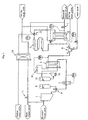
- the vapor contact-type heating device shown in Fig. 1 is used, for example, for heat sterilization of fluids, and comprises, as main components, a liquid tank 1 for storing and discharging a fluid which is an object of heat treatment, a transfer pump 2 for transferring the fluid in the liquid tank 1 to a heat exchanger 3 and a vapor mixing pump 4 described later, a heat exchanger 3 which preheats the fluid transferred from the transfer pump 2 for the purpose of bringing the temperature of the fluid close to that of the vapor to be mixed, a vapor mixing pump 4 for mixing vapor into the fluid preheated by the heat exchanger 3 and heating the fluid to a sterilization temperature, a hold pipe 5 which retains, for a certain period of time, the fluid heated by mixing vapor to stimulate the sterilizing action of the fluid, a main cooler 6 for cooling the fluid which has undergone the sterilization process in the hold pipe 5 to a predetermined temperature or lower, and a main back pressure regulating valve 7 which is arranged downstream of the main cooler 6 and retains
- numeral 8 represents a water tank which stores and discharges the water used for cleaning or sterilizing process of the fluid system (duct) in the vapor contact-type heating device
- numeral 9 represents a first switching valve which switches between a line from the liquid tank 1 and a line from the water tank 9 depending on operation conditions.
- numeral 10 represents a waste water cooler which cools the liquid so that the liquid which has been subjected to a process and the like can flow into a recovery line (waste water line) without any problem during a system sterilization process or when a sterilization process failure occurs;
- numeral 11 represents a waste water back pressure regulating valve which is provided downstream of the waste water cooler 10 and retains the back pressure of the waste water line at a constant level;
- numeral 12 represents a second switching valve for transferring the processed liquid into the recovery line (waste water line) when the liquid temperature on the outlet side of the vapor mixing pump 4 (downstream of the outlet 42 described later) or the liquid temperature on the outlet side of the hold pipe 5 falls outside a target sterilization temperature range.
- numerals 13, 14 and 15 represent a heat water tank for reserving a predetermined amount of heated water used for the heat exchanger 3 for preheating, a circulation pump for circulating hot water between the heat water tank 13 and the heat exchanger 3, and a heater which heats the hot water transferred from the circulation pump 14 to a predetermined temperature, respectively.
- a control unit for measuring and controlling the temperature and flow rate of various kinds of fluids is provided.
- numeral TICA-1 represents a sterilization temperature control unit which measures the temperature of the liquid on the outlet side of the vapor mixing pump 4 by a temperature sensor, and adjusts the amount of vapor supplied to the vapor mixing pump 4 based on this measurement value, so that the temperature of the liquid in this measurement portion falls within a required temperature range.
- numeral TICA-2 represents a cooling temperature control unit which measures the temperature of the liquid on the outlet side of the main cooler 6, and adjusts the amount of the cooling water supplied to the main cooler 6 based on this measurement value, so that the temperature of the liquid in this measurement portion falls within a required temperature range
- numeral TICA-3 represents a preheat temperature control unit which measures the temperature of the liquid on the outlet side of the heat exchanger 3, and adjusts the temperature (for example, the amount of heating by the heater 15) of the hot water used for the heat exchanger 3 based on this measurement value, so that the temperature of the liquid in this measurement portion falls within a required temperature range.
- numeral TIA-1 represents a sterilization temperature control unit which is used for switching the lines of the second switching valve 12, measures the temperature of the liquid on the outlet side of the hold pipe 5, and, when this measurement value (temperature) does not fall within a required sterilization temperature range, transmits this information to the second switching valve 12 or transmits a switch signal.
- numeral FICA-1 represents a flow rate control unit which measures the flow rate of the liquid on the outlet side of the transfer pump 2, and adjusts the number of revolutions (the frequency of an inverter in this case) of the transfer pump 2 based on this measurement value so that the flow rate of the liquid in this measurement portion falls within a predetermined range.
- Fig. 2 is a cross-sectional view of the vapor mixing pump 4 as the fluid transfer means provided with the vapor supply region thereinside, which is perpendicular to the shaft of the pump.
- the vapor mixing pump 4 comprises a casing 43 having an inlet 41 and an outlet 42 for the liquid, and a rotor 44 contained within the casing 43 and rotatably connected to the drive shaft of a motor, which is not shown, a liquid pressurizing duct 45 formed between an inner wall 43a of the casing 43 and the rotor 44, and a vapor supply port 46 which is provided on the casing 43 and opens to the pressurizing duct 45.
- a vapor supply region 47 for providing vapor to the liquid introduced into the pump 4 is formed in the opening portion of the vapor supply port 46.
- the vapor mixing pump 4 is constituted mainly of a cascade pump.
- a partition portion 48 is formed between the inlet 41 and the outlet 42, and the pressurizing duct 45, which serves as a fluid channel, is formed partly annularly along the outer periphery of the disk-shaped rotor 44 in a manner of connecting the inlet 41 and the outlet 42.
- This constitution causes the liquid which flows into the pressurizing duct 45 from the inlet 41 to flow the pressurizing duct 45 almost in a full circle of the rotor 44 and to be discharged from the outlet 42 to the outside.
- the rotor 44 is a so-called impeller in this illustrated example, and has a plurality of blade grooves 44a along its outer periphery.
- the vapor supply port 46 is provided on the side closer to the inlet 41 than the middle position of the pressurizing duct 45 in this embodiment.
- the liquid discharged from the liquid tank 1 is transferred to the heat exchanger 3 ⁇ positioned downstream of the transfer pump 2 by the transfer pump 2, and is subjected to a preheat treatment (for example, 50°C or higher but lower than 100°C) for bringing the temperature of the liquid close to that for heat treatment, which is described later.
- a preheat treatment for example, 50°C or higher but lower than 100°C
- the liquid which has bee subjected to a preheat treatment in such a manner is transferred to the vapor mixing pump 4 (fluid transfer means) positioned downstream thereof.
- the liquid transferred to the vapor mixing pump 4 is introduced into the pressurizing duct 45 from the direction of arrow a through the inlet 41, as shown in Fig. 2 .
- the rotor 44 connected to the drive shaft of the motor is rotated by driving the motor, which is not shown.
- the rotor rotates in the direction from the inlet 41 to the outlet 42 along the pressurizing duct 45 so that the liquid introduced into the pressurizing duct 45 is transferred to the side of the outlet 42 by an increase in the pressure.
- vapor is mixed into the liquid which is being transferred by an increased pressure in the vapor supply region 47 formed in the opening portion of the vapor supply port 46 by introducing vapor into the pressurizing duct 45 from the vapor supply port 46 provided on the casing 43 from the direction of arrow b.
- the liquid is heated to the heat sterilization temperature by providing vapor which is caused to have the temperature at which the heat sterilization is to be conducted or higher.
- the liquid provided with vapor is dynamically mixed (agitated) by the rotor 44, transferred toward the side of the outlet 42 through the pressurizing duct 45 while being pressurized, and is discharged to the outside (in Figs. 1 and 2 , in the direction of arrow c) via the outlet 42 with the end of the agitation and pressurization.
- the sterilization temperature control unit TICA-1 measures the temperature of the liquid on the outlet side of the vapor mixing pump 4 with a temperature sensor, and the amount of vapor supplied to the vapor mixing pump 4 is adjusted based on this measurement value, so that the temperature of the liquid in this measurement portion falls within a required temperature range. More specifically, opening and closing of a control valve arranged upstream of the vapor supply port 46 is controlled by the sterilization temperature control unit TICA-1 to adjust the flow rate of vapor.
- the liquid heated to a predetermined temperature (heat sterilization temperature) by supplying vapor is retained in the hold pipe 5 positioned downstream of the vapor mixing pump 4 for a certain period of time to carry out a substantial sterilization process of the fluid.
- a predetermined temperature heat sterilization temperature
- the liquid positioned at the outlet 42 of the vapor mixing pump 4 and downstream (including the inside of the hold pipe 5) thereof is retained under a constant pressure by the main back pressure regulating valve 7 arranged downstream of the hold pipe 5.
- the heat sterilization step is completed by cooling the liquid which has undergone the sterilization process in the hold pipe 5 to a predetermined temperature or lower in the main cooler 6 (for example, lower than 100°C).
- the liquid pressurizing duct 45 is provided within the vapor mixing pump 4 as a fluid transfer means, the vapor supply port 46 is provided on this pressurizing duct 45, and the vapor supply region 47 is formed within the pressurizing duct 45 is used for mixing vapor. Therefore, the liquid which is being pressurized and transferred can be supplied with vapor with agitation by the action of the rotor 44, which allows vapor to be uniformly mixed into the fluid, achieving stable heat treatment with little unevenness.
- the pressure of vapor required can be lower than in a conventional case where, for example, vapor is mixed downstream of the pump as in conventional devices, and the generation of cavitation during heating can be also suppressed. Therefore, it is possible to avoid heating the liquid above the required sterilization temperature and suppress heat damage to the liquid to a low level, whereby the degradation of the quality can be minimized and sufficient heat sterilization process can be carried out at the same time.
- the pump vapor mixing pump 4
- the amount of increase in the pressure of the liquid (pressurization gradient) in the pressurizing duct 45 can be adjusted by the number of revolutions of the rotor 44. Accordingly, quantitative control of the pressure of vapor supplied and the pressure of the fluid within the pump 4 are made possible. For example, necessary pressure of vapor supplied ( ⁇ saturated vapor pressure at the sterilization temperature) is determined depending on a desired sterilization temperature, and therefore it is also possible to adjust the number of revolutions (of the rotor 44) of the pump so that the liquid pressure in the vapor supply region 47 becomes slightly lower than the vapor pressure. Since the pressure balance can be adjusted by the number of revolutions of the pump 4 in such a manner, vapor having a temperature suitable for the liquid can be readily introduced, and the types of liquids which can be subjected to heat sterilization can be thus increased.
- the main back pressure regulating valve 7 is provided downstream of the outlet 42 of the vapor mixing pump 4, the fluid pressure can be retained at a predetermined value in the hold pipe 5 arranged downstream of the vapor mixing pump 4. Accordingly, the vapor-liquid mixture can be maintained at a high pressure so that the vapor in the liquid does not cause cavitation once it is dissolved therein, achieving more stable heat sterilization.
- the liquid pressure on the outlet side of the pump 4 is controlled by the main back pressure regulating valve 7, and therefore the number of revolutions of the pump 4 substantially controls the liquid pressure on the inlet side of the pump 4.
- more preferable heat sterilization control is achieved by adjusting the amount of vapor supplied by the sterilization temperature control unit TICA-1, measuring the pressure on the outlet side of the pump by a pressure sensor or the like, which is not illustrated, and controlling the amount of opening and closing of the main back pressure regulating valve 7 based on such a pressure value (flow rate). That is, more precise and stable heat sterilization process is achieved by using the number of revolutions of the vapor mixing pump 4, the temperature of the liquid on the outlet side of the pump, and the pressure of the liquid on the outlet side of the pump as control parameters. Therefore, precise and easy adjustment of a sterilization temperature required for a particular food is made possible even in the heat sterilization process of a liquid food with which subtle adjustments are necessary.
- a so-called cascade pump peripheral pump
- This type of pump can produce very high pressurization effect compared to other pumps. Therefore, the pump is suitable for applications where it is necessary to smoothly introduce vapor having as low pressure as possible into the liquid and high pressurization effect as well as heating is required for the purpose of preventing cavitation, as in this type of heat sterilization process.
- the present invention is not limited to this embodiment, and can be also applied to a vapor contact-type heating device having a constitution other than that described above.
- the portion (the vapor mixing pump 4 as a fluid transfer means) according to the features of the present invention is of course not limited to the form stated above, and various modifications can be made within the scope of the invention.
- the vapor supply port 46 for supplying vapor to the pressurizing duct 45 within the vapor mixing pump 4 is provided on the casing 43 in such a manner that it opens on the side closer to the inlet 41 than the middle position of the pressurizing duct 45 has been shown as an example, but the opening position can be optionally selected.
- the vapor supply port 46 can be provided on the casing 43 so that the opening opens on the side closer to the outlet 42 than the middle position of the pressurizing duct 45.
- pressurizing characteristics vary depending on the shapes of the pressurizing duct 45 and the rotor 44 for some types of the pump used as the vapor mixing pump 4, and therefore controlling may be easier in some cases if the position of the vapor supply port 46 arranged depending on the heat sterilization temperature and the type of its processed fluid are variable parameters.
- a peripheral pump was applied as the vapor mixing pump 4
- the pump is not limited to this, and various pumps can be used.
- examples of usable pumps include non-positive displacement pumps such as centrifugal pumps and the like, and rotary positive displacement pumps such as rotary pumps, screw pumps and the like.
- the shape of the rotor 44 is not critical either.
- various fluid transfer means other than pumps can be used as long as they comprise the rotor 44 and are capable of increasing the pressure of the fluid and dynamically mixing the same simultaneously by the rotational action thereof.
- control unit for measuring and controlling the fluid temperatures and flow rates of various kinds of fluids is provided to control the heat sterilization process. That is, the case where the heat sterilization temperature and the pressure balance within the vapor mixing pump 4 are controlled by using the temperature of the liquid on the outlet side of the pump, the number of revolutions of the pump and the flow rate of vapor as control parameters has been shown as an example, but of course controlling can be carried out by using other parameters as control parameters.
- control valves it is possible to open and close various kinds of control valves by feeding back the pressure value in each point (e.g., the value of the pressure of the liquid measured on the inlet side of the pump, the value of the pressure of vapor measured upstream of the vapor supply port 46) with a pressure sensor, so that the sterilization temperature and the pressure balance within the pump stated above, or the amount of vapor supplied, etc., are controlled.
- the sterilization process can be also controlled in a state that the number of revolutions of the pump is a fixed parameter.
- the sterilization process can be also controlled by adjusting the amount of vapor supplied by the sterilization temperature control unit TICA-1 with a fixed number of revolutions of the pump and the main back pressure regulating valve 7 being capable of adjusting the pressure of itself.
- the vapor contact-type heating device is applied to the heat sterilization process of the liquid, but of course the application of the device is not limited to this. It can be suitably used to heat various liquids as, for example, a continuous liquid heating device, a hot water manufacturing device, etc., utilizing its excellent heating temperature controllability and its stability.
- the vapor contact-type heating device according to the present invention was used to conduct a heat sterilization process of a fluid, and the processing performance in this process was evaluated.
- a pressure P2 MPa of the liquid on the outlet side (downstream of the outlet 42 of the vapor mixing pump 4) of the pump was set to have a predetermined value by the main back pressure regulating valve 7, and the pressure P1 MPa of the liquid on the inlet side of the pump was set to have a predetermined value by adjusting the number n Hz of revolutions of the pump.
- the amount of vapor supplied was controlled by the aforementioned control unit (sterilization temperature control unit TICA-1) based on a temperature T2 °C on the outlet side of the pump so that the liquid after vapor has been mixed thereinto had a target heat sterilization temperature T0 °C.
- T1 represents the temperature °C of the liquid on the inlet side of the pump
- P3 represents the pressure MPa of vapor introduced (the original pressure of the vapor introduced is shown on the left in the frame, and the pressure of the vapor at the inlet of the casing is shown on the right)
- P4 represents the pressure MPa of the liquid in the middle position of the pump (e.g., in Fig. 2 , the pressure of the liquid in the position indicated by the broken line)
- Q1 represents the flow rate UH of the liquid on the inlet side of the pump.
Abstract
Description
- The present invention relates to a fluid heating device, especially a vapor contact-type heating device which heats a fluid by bringing vapor into direct contact with the fluid.
- Heating devices of this type are used for various fluid heating devices, for example, continuous liquid heating devices, continuous liquid sterilization devices, and hot water manufacturing devices.
- Examples of methods for sterilizing liquid foods include the indirect heating method in which the food is heated indirectly through a metal wall and the like, and the direct vapor heating method in which the liquid is directly heated by vapor. Among these, there is a trend that as a method for sterilizing liquids which are easily burnt, such as coffee creamer and soybean milk, or liquids which are easily discolored, such as aojiru (juice of green, leafy vegetables), the direct vapor heating method which requires a shorter heating time, has small thermal effect on the liquid, and is capable of preventing degradation of the quality of the liquid is preferably used.
- For example, Japanese Unexamined Patent Publication No.
2004-201533 - Japanese Unexamined Patent Publication No.
2000-300976 -
Patent Document 2 describes that a dispersive mixer disclosed in Japanese Utility Model Publication No.1995-37703 Patent Document 3 mainly comprises, thereinside, a conduit pipe for passing a main fluid (fluid to be heated) on which a stirring element such as a twisted plate is fixed, a nozzle connected to the inside of this conduit pipe, and a header for infusing an infusion fluid (vapor) into the conduit pipe via this nozzle, and a force-feed means for force-feeding the infusion fluid to the header. - As mentioned above, static mixing methods are adopted as methods for mixing vapor into a liquid, as disclosed in
Patent Documents - Since the fluid to be heated and fed to the mixer stated above is transferred by a metering pump, the pressure of the fluid is high, and a correspondingly high liquid pressure is necessary for the fluid to pass through the stirring element as stated above. Therefore, in order to mix vapor into the fluid to be heated in the mixer arranged downstream of the pump, a vapor pressure higher than the discharge pressure of the pump is necessary, and a high vapor supply pressure is required as a result. In this manner, the fluid is unnecessarily heated at a temperature higher than the desired sterilization temperature, which may undesirably cause heat damage to the fluid to be heated and thus lowered quality of the fluid.
- In view of the foregoing, it is a technical object of the present invention to provide a vapor contact-type heating device which can increase the mixing efficiency of vapor and realize a high-quality heat treatment by providing vapor at a relatively low pressure.
- In order to achieve the object mentioned above, the present invention provides a vapor contact-type heating device which comprises a fluid transfer means which transfers a fluid with an increase in pressure by the action of a rotor, and a vapor supply region which supplies vapor to the fluid, wherein the fluid transfer means is provided with an inlet and an outlet of the fluid, and a pressurizing duct is formed between the inlet and the outlet, and a vapor supply region is arranged in the pressurizing duct by providing a supply port of vapor on the pressurizing duct.
- According to the constitution stated above, the fluid is transferred by the action of the rotor, and simultaneously vapor is blown into the vapor supply region provided in the pressurizing duct via the vapor supply port, whereby mixing of the fluid and vapor inside the fluid transfer means and increasing the pressure of the mixed fluid are simultaneously carried out. Normally, the rotor arranged inside the fluid transfer means forms a pressurizing duct, or faces the duct, and therefore the fluid and the vapor provided for the fluid are agitated and mixed by rotating such a rotor. Accordingly, dynamic mixing of the fluid and vapor is made possible, and vapor can be mixed into the fluid uniformly.
- By mixing vapor into the fluid which is in the pressurizing duct inside the fluid transfer means and is being transferred from the inlet to the outlet by an increase in the pressure, it is possible to supply vapor at a pressure lower than in a case where vapor is supplied after the pressure of the fluid has been increased as in a known example. Accordingly, the temperature of the vapor to be supplied can be relatively low, which causes no heat damage to the fluid to be heated caused by unnecessary heating, or deterioration of the quality of the fluid. Moreover, low-pressure vapor, which has a smaller fluctuation in pressure, allows stable heat treatment. Furthermore, since arranging the vapor supply region in the pressurizing duct allows increasing the pressure of the fluid even after the vapor has been supplied, cavitation, which may be caused with an increase in the temperature of the liquid caused by supplying vapor, can be avoided as much as possible. This allows vapor to be uniformly dissolved into the fluid, achieving stable heat treatment with little variation.
- The fluid transfer means provided with the vapor supply region thereinside may be any device which comprises a rotor and is capable of increasing the pressure of the fluid and dynamically mix the same simultaneously by the rotational action of the rotor. Specific examples of such means include non-positive displacement pumps typically including centrifugal pumps and peripheral pumps, or rotary positive displacement pumps such as rotary pumps and screw pumps. In this case, the pressurization effect of the pump is normally produced by the rotor arranged inside the pump, which converts the rotation energy of itself into a pressure energy and imparts it to the fluid, and therefore the amount of pressure increased can be adjusted, for example, by the number of revolutions of the rotor. This enables the quantitative control of the pressure of vapor supplied and the pressure of the fluid within the pump, and also readily realizes its automation. Moreover, since the pressure balance can be adjusted by the number of revolutions of the pump, vapor having a temperature desirable for the fluid can be readily introduced. This allows application of the heating device according to the present invention to various fluids.
- When the fluid is sterilized with heating by using the heating device according to the present invention, it is often the case that substantially effective and sufficient sterilization is carried out by retaining the fluid heated by a hold pipe arranged downstream of the fluid transfer means for supplying vapor for a certain period of time. Accordingly, the fluid pressure actually needs to be maintained at a high level further downstream of the fluid transfer means. From such a perspective, in the present invention, the pressure of the fluid at the outlet provided in the fluid transfer means and downstream thereof is maintained higher than the pressure of vapor at the supply port of vapor. More specifically, a back pressure regulating valve is provided downstream of the outlet of the fluid transfer means.
- By providing such a constituting, the fluid pressure (outlet pressure) at the outlet of the fluid transfer means can be retained at a predetermined value. Accordingly, the vapor mixed fluid can be maintained at a high pressure so that the vapor which has once been dissolved in the fluid does not cause cavitation, achieving more stable heat sterilization. Moreover, if the pressure on the outlet side of the pump can be set as stated above, the pressure balance in the vapor supply region can be controlled more accurately by setting the number of revolutions of the pump simultaneously. Accordingly, visualization of adjustment parameters of the pressure balance is achieved, and precise and stable operation is made possible. In particular, in a heat sterilization process of a liquid food with which subtle adjustments are necessary, required sterilization temperature may vary depending on the food. However, even in this case, a vapor pressure (temperature) which can be provided is determined based on a saturated vapor pressure depending on the sterilization temperature. Therefore, the back pressure and number of revolutions of the pump may be set so that such vapor can be provided. Accordingly, appropriate vapor which is desirable the fluid to be heated can be provided, and for example, various heat sterilization processes can be readily handled.
- As mentioned above, according to the present invention, it is possible to provide a vapor contact-type heating device which can increase the mixing efficiency of vapor and realize a high-quality heat treatment by providing vapor at a relatively low pressure.
- One embodiment of the vapor contact-type heating device according to the present invention will be described below with reference to drawings.
- The vapor contact-type heating device shown in
Fig. 1 is used, for example, for heat sterilization of fluids, and comprises, as main components, aliquid tank 1 for storing and discharging a fluid which is an object of heat treatment, atransfer pump 2 for transferring the fluid in theliquid tank 1 to aheat exchanger 3 and avapor mixing pump 4 described later, aheat exchanger 3 which preheats the fluid transferred from thetransfer pump 2 for the purpose of bringing the temperature of the fluid close to that of the vapor to be mixed, avapor mixing pump 4 for mixing vapor into the fluid preheated by theheat exchanger 3 and heating the fluid to a sterilization temperature, ahold pipe 5 which retains, for a certain period of time, the fluid heated by mixing vapor to stimulate the sterilizing action of the fluid, a main cooler 6 for cooling the fluid which has undergone the sterilization process in thehold pipe 5 to a predetermined temperature or lower, and a main back pressure regulating valve 7 which is arranged downstream of the main cooler 6 and retains the back pressure at a constant level. - In
Fig. 1 ,numeral 8 represents a water tank which stores and discharges the water used for cleaning or sterilizing process of the fluid system (duct) in the vapor contact-type heating device, andnumeral 9 represents a first switching valve which switches between a line from theliquid tank 1 and a line from thewater tank 9 depending on operation conditions. - In the same Fig.,
numeral 10 represents a waste water cooler which cools the liquid so that the liquid which has been subjected to a process and the like can flow into a recovery line (waste water line) without any problem during a system sterilization process or when a sterilization process failure occurs;numeral 11 represents a waste water back pressure regulating valve which is provided downstream of thewaste water cooler 10 and retains the back pressure of the waste water line at a constant level; andnumeral 12 represents a second switching valve for transferring the processed liquid into the recovery line (waste water line) when the liquid temperature on the outlet side of the vapor mixing pump 4 (downstream of theoutlet 42 described later) or the liquid temperature on the outlet side of thehold pipe 5 falls outside a target sterilization temperature range. - In the same Fig.,
numerals heat exchanger 3 for preheating, a circulation pump for circulating hot water between theheat water tank 13 and theheat exchanger 3, and a heater which heats the hot water transferred from thecirculation pump 14 to a predetermined temperature, respectively. - In this embodiment, a control unit for measuring and controlling the temperature and flow rate of various kinds of fluids is provided. For example, in
Fig. 1 , numeral TICA-1 represents a sterilization temperature control unit which measures the temperature of the liquid on the outlet side of thevapor mixing pump 4 by a temperature sensor, and adjusts the amount of vapor supplied to thevapor mixing pump 4 based on this measurement value, so that the temperature of the liquid in this measurement portion falls within a required temperature range. Similarly, numeral TICA-2 represents a cooling temperature control unit which measures the temperature of the liquid on the outlet side of the main cooler 6, and adjusts the amount of the cooling water supplied to the main cooler 6 based on this measurement value, so that the temperature of the liquid in this measurement portion falls within a required temperature range, and numeral TICA-3 represents a preheat temperature control unit which measures the temperature of the liquid on the outlet side of theheat exchanger 3, and adjusts the temperature (for example, the amount of heating by the heater 15) of the hot water used for theheat exchanger 3 based on this measurement value, so that the temperature of the liquid in this measurement portion falls within a required temperature range. - In
Fig. 1 , numeral TIA-1 represents a sterilization temperature control unit which is used for switching the lines of thesecond switching valve 12, measures the temperature of the liquid on the outlet side of thehold pipe 5, and, when this measurement value (temperature) does not fall within a required sterilization temperature range, transmits this information to thesecond switching valve 12 or transmits a switch signal. Moreover, numeral FICA-1 represents a flow rate control unit which measures the flow rate of the liquid on the outlet side of thetransfer pump 2, and adjusts the number of revolutions (the frequency of an inverter in this case) of thetransfer pump 2 based on this measurement value so that the flow rate of the liquid in this measurement portion falls within a predetermined range. - The constitution of the
vapor mixing pump 4 will be now described. -
Fig. 2 is a cross-sectional view of thevapor mixing pump 4 as the fluid transfer means provided with the vapor supply region thereinside, which is perpendicular to the shaft of the pump. As shown in this Fig., thevapor mixing pump 4 comprises acasing 43 having aninlet 41 and anoutlet 42 for the liquid, and arotor 44 contained within thecasing 43 and rotatably connected to the drive shaft of a motor, which is not shown, a liquid pressurizingduct 45 formed between aninner wall 43a of thecasing 43 and therotor 44, and avapor supply port 46 which is provided on thecasing 43 and opens to the pressurizingduct 45. According to such a constitution, during rotation of therotor 44 and introduction of vapor, avapor supply region 47 for providing vapor to the liquid introduced into thepump 4 is formed in the opening portion of thevapor supply port 46. - In this embodiment, the
vapor mixing pump 4 is constituted mainly of a cascade pump. Apartition portion 48 is formed between theinlet 41 and theoutlet 42, and thepressurizing duct 45, which serves as a fluid channel, is formed partly annularly along the outer periphery of the disk-shaped rotor 44 in a manner of connecting theinlet 41 and theoutlet 42. This constitution causes the liquid which flows into the pressurizingduct 45 from theinlet 41 to flow the pressurizingduct 45 almost in a full circle of therotor 44 and to be discharged from theoutlet 42 to the outside. Therotor 44 is a so-called impeller in this illustrated example, and has a plurality ofblade grooves 44a along its outer periphery. Moreover, thevapor supply port 46 is provided on the side closer to theinlet 41 than the middle position of the pressurizingduct 45 in this embodiment. - An example of the heat sterilization step of the processed liquid when the heating device having the constitution described above is used will be now described.
- First, as shown in
Fig. 1 , the liquid discharged from theliquid tank 1 is transferred to theheat exchanger 3□positioned downstream of thetransfer pump 2 by thetransfer pump 2, and is subjected to a preheat treatment (for example, 50°C or higher but lower than 100°C) for bringing the temperature of the liquid close to that for heat treatment, which is described later. The liquid which has bee subjected to a preheat treatment in such a manner is transferred to the vapor mixing pump 4 (fluid transfer means) positioned downstream thereof. - The liquid transferred to the
vapor mixing pump 4 is introduced into the pressurizingduct 45 from the direction of arrow a through theinlet 41, as shown inFig. 2 . At this time, therotor 44 connected to the drive shaft of the motor is rotated by driving the motor, which is not shown. In this embodiment, the rotor rotates in the direction from theinlet 41 to theoutlet 42 along the pressurizingduct 45 so that the liquid introduced into the pressurizingduct 45 is transferred to the side of theoutlet 42 by an increase in the pressure. Simultaneously, vapor is mixed into the liquid which is being transferred by an increased pressure in thevapor supply region 47 formed in the opening portion of thevapor supply port 46 by introducing vapor into the pressurizingduct 45 from thevapor supply port 46 provided on thecasing 43 from the direction of arrow b. The liquid is heated to the heat sterilization temperature by providing vapor which is caused to have the temperature at which the heat sterilization is to be conducted or higher. - The liquid provided with vapor is dynamically mixed (agitated) by the
rotor 44, transferred toward the side of theoutlet 42 through the pressurizingduct 45 while being pressurized, and is discharged to the outside (inFigs. 1 and2 , in the direction of arrow c) via theoutlet 42 with the end of the agitation and pressurization. In this embodiment, the sterilization temperature control unit TICA-1 measures the temperature of the liquid on the outlet side of thevapor mixing pump 4 with a temperature sensor, and the amount of vapor supplied to thevapor mixing pump 4 is adjusted based on this measurement value, so that the temperature of the liquid in this measurement portion falls within a required temperature range. More specifically, opening and closing of a control valve arranged upstream of thevapor supply port 46 is controlled by the sterilization temperature control unit TICA-1 to adjust the flow rate of vapor. - The liquid heated to a predetermined temperature (heat sterilization temperature) by supplying vapor is retained in the
hold pipe 5 positioned downstream of thevapor mixing pump 4 for a certain period of time to carry out a substantial sterilization process of the fluid. At this time, the liquid positioned at theoutlet 42 of thevapor mixing pump 4 and downstream (including the inside of the hold pipe 5) thereof is retained under a constant pressure by the main back pressure regulating valve 7 arranged downstream of thehold pipe 5. - Thereafter, the heat sterilization step is completed by cooling the liquid which has undergone the sterilization process in the
hold pipe 5 to a predetermined temperature or lower in the main cooler 6 (for example, lower than 100°C). - As mentioned above, a constitution in which the
liquid pressurizing duct 45 is provided within thevapor mixing pump 4 as a fluid transfer means, thevapor supply port 46 is provided on this pressurizingduct 45, and thevapor supply region 47 is formed within the pressurizingduct 45 is used for mixing vapor. Therefore, the liquid which is being pressurized and transferred can be supplied with vapor with agitation by the action of therotor 44, which allows vapor to be uniformly mixed into the fluid, achieving stable heat treatment with little unevenness. Moreover, by mixing vapor into the liquid which is being pressurized and transferred, the pressure of vapor required can be lower than in a conventional case where, for example, vapor is mixed downstream of the pump as in conventional devices, and the generation of cavitation during heating can be also suppressed. Therefore, it is possible to avoid heating the liquid above the required sterilization temperature and suppress heat damage to the liquid to a low level, whereby the degradation of the quality can be minimized and sufficient heat sterilization process can be carried out at the same time. - As in this embodiment, by applying the pump (vapor mixing pump 4) as the fluid transfer means, the amount of increase in the pressure of the liquid (pressurization gradient) in the pressurizing
duct 45 can be adjusted by the number of revolutions of therotor 44. Accordingly, quantitative control of the pressure of vapor supplied and the pressure of the fluid within thepump 4 are made possible. For example, necessary pressure of vapor supplied (≤ saturated vapor pressure at the sterilization temperature) is determined depending on a desired sterilization temperature, and therefore it is also possible to adjust the number of revolutions (of the rotor 44) of the pump so that the liquid pressure in thevapor supply region 47 becomes slightly lower than the vapor pressure. Since the pressure balance can be adjusted by the number of revolutions of thepump 4 in such a manner, vapor having a temperature suitable for the liquid can be readily introduced, and the types of liquids which can be subjected to heat sterilization can be thus increased. - In this embodiment, since the main back pressure regulating valve 7 is provided downstream of the
outlet 42 of thevapor mixing pump 4, the fluid pressure can be retained at a predetermined value in thehold pipe 5 arranged downstream of thevapor mixing pump 4. Accordingly, the vapor-liquid mixture can be maintained at a high pressure so that the vapor in the liquid does not cause cavitation once it is dissolved therein, achieving more stable heat sterilization. In this case, the liquid pressure on the outlet side of thepump 4 is controlled by the main back pressure regulating valve 7, and therefore the number of revolutions of thepump 4 substantially controls the liquid pressure on the inlet side of thepump 4. - Given the foregoing, more preferable heat sterilization control is achieved by adjusting the amount of vapor supplied by the sterilization temperature control unit TICA-1, measuring the pressure on the outlet side of the pump by a pressure sensor or the like, which is not illustrated, and controlling the amount of opening and closing of the main back pressure regulating valve 7 based on such a pressure value (flow rate). That is, more precise and stable heat sterilization process is achieved by using the number of revolutions of the
vapor mixing pump 4, the temperature of the liquid on the outlet side of the pump, and the pressure of the liquid on the outlet side of the pump as control parameters. Therefore, precise and easy adjustment of a sterilization temperature required for a particular food is made possible even in the heat sterilization process of a liquid food with which subtle adjustments are necessary. In particular, re-heating, which cannot be conducted in vapor contact type heating methods since the liquid is diluted, can be carried out in this heating device (heat sterilization control means) since highly accurate and stable heat sterilization process is possible, thereby offering a very effective means of heat sterilization process. - In this embodiment, a so-called cascade pump (peripheral pump) is used as the
vapor mixing pump 4. This type of pump can produce very high pressurization effect compared to other pumps. Therefore, the pump is suitable for applications where it is necessary to smoothly introduce vapor having as low pressure as possible into the liquid and high pressurization effect as well as heating is required for the purpose of preventing cavitation, as in this type of heat sterilization process. - One embodiment of the vapor contact-type heating device according to the present invention has been described above, but the present invention is not limited to this embodiment, and can be also applied to a vapor contact-type heating device having a constitution other than that described above. Moreover, the portion (the
vapor mixing pump 4 as a fluid transfer means) according to the features of the present invention is of course not limited to the form stated above, and various modifications can be made within the scope of the invention. - In the above embodiment, the case where the
vapor supply port 46 for supplying vapor to the pressurizingduct 45 within thevapor mixing pump 4 is provided on thecasing 43 in such a manner that it opens on the side closer to theinlet 41 than the middle position of the pressurizingduct 45 has been shown as an example, but the opening position can be optionally selected. For example, as shown by the broken line inFig. 2 , thevapor supply port 46 can be provided on thecasing 43 so that the opening opens on the side closer to theoutlet 42 than the middle position of the pressurizingduct 45. This is because the pressurizing characteristics vary depending on the shapes of the pressurizingduct 45 and therotor 44 for some types of the pump used as thevapor mixing pump 4, and therefore controlling may be easier in some cases if the position of thevapor supply port 46 arranged depending on the heat sterilization temperature and the type of its processed fluid are variable parameters. - In the above embodiment, the case where a peripheral pump was applied as the
vapor mixing pump 4 was described, but the pump is not limited to this, and various pumps can be used. Examples of usable pumps include non-positive displacement pumps such as centrifugal pumps and the like, and rotary positive displacement pumps such as rotary pumps, screw pumps and the like. The shape of therotor 44 is not critical either. Of course, various fluid transfer means other than pumps can be used as long as they comprise therotor 44 and are capable of increasing the pressure of the fluid and dynamically mixing the same simultaneously by the rotational action thereof. - In the above embodiment, the case where the control unit for measuring and controlling the fluid temperatures and flow rates of various kinds of fluids is provided to control the heat sterilization process has been described. That is, the case where the heat sterilization temperature and the pressure balance within the
vapor mixing pump 4 are controlled by using the temperature of the liquid on the outlet side of the pump, the number of revolutions of the pump and the flow rate of vapor as control parameters has been shown as an example, but of course controlling can be carried out by using other parameters as control parameters. For example, it is possible to open and close various kinds of control valves by feeding back the pressure value in each point (e.g., the value of the pressure of the liquid measured on the inlet side of the pump, the value of the pressure of vapor measured upstream of the vapor supply port 46) with a pressure sensor, so that the sterilization temperature and the pressure balance within the pump stated above, or the amount of vapor supplied, etc., are controlled. Of course, the sterilization process can be also controlled in a state that the number of revolutions of the pump is a fixed parameter. For example, the sterilization process can be also controlled by adjusting the amount of vapor supplied by the sterilization temperature control unit TICA-1 with a fixed number of revolutions of the pump and the main back pressure regulating valve 7 being capable of adjusting the pressure of itself. - In the above embodiment, the case where the vapor contact-type heating device is applied to the heat sterilization process of the liquid has been described, but of course the application of the device is not limited to this. It can be suitably used to heat various liquids as, for example, a continuous liquid heating device, a hot water manufacturing device, etc., utilizing its excellent heating temperature controllability and its stability.
-
-
Fig. 1 is a schematic diagram which shows a constitutional example of the vapor contact-type heating device according to the present invention. -
Fig. 2 is a cross-sectional view of the pump for mixing vapor perpendicular to the shaft of the pump. -
Fig. 3 shows the results of the liquid heating test in which the heating device according to the present invention was used. - To demonstrate the advantages of the present invention, the vapor contact-type heating device according to the present invention was used to conduct a heat sterilization process of a fluid, and the processing performance in this process was evaluated.
- More specifically, in the constitution according to
Fig. 1 , a pressure P2 MPa of the liquid on the outlet side (downstream of theoutlet 42 of the vapor mixing pump 4) of the pump was set to have a predetermined value by the main back pressure regulating valve 7, and the pressure P1 MPa of the liquid on the inlet side of the pump was set to have a predetermined value by adjusting the number n Hz of revolutions of the pump. Moreover, the amount of vapor supplied was controlled by the aforementioned control unit (sterilization temperature control unit TICA-1) based on a temperature T2 °C on the outlet side of the pump so that the liquid after vapor has been mixed thereinto had a target heat sterilization temperature T0 °C. - The results of the experiment are shown in
Fig. 3 . Herein, T1 represents the temperature °C of the liquid on the inlet side of the pump; P3 represents the pressure MPa of vapor introduced (the original pressure of the vapor introduced is shown on the left in the frame, and the pressure of the vapor at the inlet of the casing is shown on the right); P4 represents the pressure MPa of the liquid in the middle position of the pump (e.g., inFig. 2 , the pressure of the liquid in the position indicated by the broken line); and Q1 represents the flow rate UH of the liquid on the inlet side of the pump. These results shows that highly accurate temperature control with very little error is possible in any temperature setting, and in this case, the pressure of vapor supplied (pressure P3 of vapor introduced) is lower than pressure P2 on the outlet side of the pump. That is, it can be seen that the vapor pressure which can be supplied is equal to or lower than the saturated vapor pressure which varies depending to the above temperature setting, but, as inFig. 3 , controlling the pressure P1 on the inlet side of the pump and the pressure P2 on the outlet side enables supplying low-pressure (low-temperature) vapor. -
-
Fig. 1 is a schematic diagram which shows a constitutional example of the vapor contact-type heating device according to the present invention. -
Fig. 2 is a cross-sectional view of the pump for mixing vapor perpendicular to the shaft of the pump. -
Fig. 3 shows the results of the liquid heating test in which the heating device according to the present invention was used.
Claims (6)
- A vapor contact-type heating device comprising a fluid transfer means which transfers a fluid with an increase in pressure by the action of a rotor, and a vapor supply region which supplies vapor to the fluid,
wherein the fluid transfer means is provided with an inlet and an outlet of the fluid, a fluid pressurizing duct of the fluid is formed between the inlet and the outlet, and
a vapor supply region is arranged in the pressurizing duct by providing a supply port for the vapor on the pressurizing duct. - A vapor contact-type heating device according to claim 1, wherein the fluid transfer means is a non-positive displacement pump.
- A vapor contact-type heating device according to claim 2, wherein the pump is a centrifugal pump.
- A vapor contact-type heating device according to claim 2, wherein the pump is a peripheral pump.
- A vapor contact-type heating device according to claim 1, wherein the fluid transfer means is a rotary positive displacement pump.
- A vapor contact-type heating device according to claim 1, wherein the pressure of the fluid at the outlet and downstream thereof is maintained higher than that at the supply port of vapor.
Applications Claiming Priority (2)
| Application Number | Priority Date | Filing Date | Title |
|---|---|---|---|
| JP2006304429A JP4602311B2 (en) | 2006-11-09 | 2006-11-09 | Steam contact heat sterilizer |
| PCT/JP2007/071584 WO2008056683A1 (en) | 2006-11-09 | 2007-11-06 | Vapor contact-type heating device |
Publications (3)
| Publication Number | Publication Date |
|---|---|
| EP2080974A1 true EP2080974A1 (en) | 2009-07-22 |
| EP2080974A4 EP2080974A4 (en) | 2011-11-09 |
| EP2080974B1 EP2080974B1 (en) | 2014-05-14 |
Family
ID=39364498
Family Applications (1)
| Application Number | Title | Priority Date | Filing Date |
|---|---|---|---|
| EP07831316.0A Not-in-force EP2080974B1 (en) | 2006-11-09 | 2007-11-06 | Peripheral pump which mixes steam to the driven liquid |
Country Status (6)
| Country | Link |
|---|---|
| US (1) | US8262066B2 (en) |
| EP (1) | EP2080974B1 (en) |
| JP (1) | JP4602311B2 (en) |
| KR (1) | KR101393473B1 (en) |
| CN (1) | CN101535757B (en) |
| WO (1) | WO2008056683A1 (en) |
Cited By (2)
| Publication number | Priority date | Publication date | Assignee | Title |
|---|---|---|---|---|
| EP2255680A1 (en) * | 2009-05-28 | 2010-12-01 | SPX APV Danmark A/S | Food product heat treatment apparatus and method for heat treating food products |
| CN102652543A (en) * | 2012-05-22 | 2012-09-05 | 江南大学 | Floating type liquid food material heating device |
Families Citing this family (5)
| Publication number | Priority date | Publication date | Assignee | Title |
|---|---|---|---|---|
| JP2009268431A (en) * | 2008-05-09 | 2009-11-19 | Hisaka Works Ltd | Steam-mixing-type heat sterilizer |
| JP5838720B2 (en) * | 2011-10-25 | 2016-01-06 | 大日本印刷株式会社 | Sterilization treatment line and purification method thereof |
| US20140348988A1 (en) * | 2011-12-12 | 2014-11-27 | Bühler Barth Gmbh | Method and Device for the Pasteurization and/or Sterilization of a Food |
| CN103673663B (en) * | 2013-11-15 | 2016-01-20 | 苏州金宏气体股份有限公司 | A kind of method of saving during ultra-pure ammonia is produced the energy of vaporizing |
| DE102017004213A1 (en) * | 2017-04-29 | 2018-10-31 | Gea Tds Gmbh | Method and plant for controlling and / or regulating the treatment of heat-sensitive liquid food products |
Citations (6)
| Publication number | Priority date | Publication date | Assignee | Title |
|---|---|---|---|---|
| US2077227A (en) * | 1934-08-10 | 1937-04-13 | Bethune Gaston S P De | Continuous heat exchange between a condensing vapor and a liquid |
| US2492635A (en) * | 1947-01-17 | 1949-12-27 | Golden State Company Ltd | Method and apparatus for heating milk |
| US3182975A (en) * | 1961-05-04 | 1965-05-11 | Nodaway Valley Foods Inc | Steam injection heater |
| US3241475A (en) * | 1960-12-27 | 1966-03-22 | Swift & Co | Canning |
| US3973048A (en) * | 1973-12-21 | 1976-08-03 | Tetra Pak Development Sa | Method for sterilizing liquids by brief heating |
| JPH02294593A (en) * | 1989-05-09 | 1990-12-05 | Nikoku Kikai Kogyo Kk | Vortex flow pump |
Family Cites Families (17)
| Publication number | Priority date | Publication date | Assignee | Title |
|---|---|---|---|---|
| US1927376A (en) * | 1929-02-06 | 1933-09-19 | Schroder Einer | Process and apparatus for the mechanical production of froth |
| US2098378A (en) * | 1934-11-08 | 1937-11-09 | Adiel Y Dodge | Air-circulating equipment |
| US2577095A (en) * | 1946-10-25 | 1951-12-04 | American Well Works | Apparatus for dispersing material in a fluid stream |
| US2663556A (en) * | 1950-05-29 | 1953-12-22 | Kostka Franz | Device for selectively dispensing ordinary and carbonated water |
| US2717770A (en) * | 1951-01-15 | 1955-09-13 | Gibson John Edwin | Pump devices for producing foam |
| JPS412110B1 (en) * | 1964-02-12 | 1966-02-14 | ||
| US3837627A (en) * | 1972-06-07 | 1974-09-24 | Allis Chalmers | Method and apparatus for gasifying a liquid |
| JP2799341B2 (en) * | 1989-05-12 | 1998-09-17 | 株式会社日阪製作所 | Back pressure applying structure in heat sterilizer for solid-containing liquid |
| JPH0737703A (en) | 1993-07-16 | 1995-02-07 | Murata Mfg Co Ltd | Positive temperature characteristic resin composition |
| JPH0737703U (en) | 1993-12-27 | 1995-07-11 | トルク精密工業株式会社 | Flexible caster |
| US5582777A (en) * | 1995-05-01 | 1996-12-10 | Keepalive, Inc. | Live well aerator and method for aeration |
| US6394423B1 (en) * | 1997-11-19 | 2002-05-28 | Thomas Joseph Vento | Multi-stage aerator |
| JPH11262363A (en) * | 1998-03-17 | 1999-09-28 | Hisaka Works Ltd | Production of rice gruel, risotto or the like by continuous pasteurizer and apparatus for producing the same |
| US6050550A (en) * | 1998-07-09 | 2000-04-18 | Burgess; Harry L. | Apparatus for aeration and bottom agitation for aqua-culture systems |
| JP3352051B2 (en) | 1999-04-16 | 2002-12-03 | 株式会社ノリタケカンパニーリミテド | Low pressure tube continuous heating device |
| JP2004201533A (en) | 2002-12-24 | 2004-07-22 | Morinaga Milk Ind Co Ltd | Method for operating steam blowing-in type direct heating sterilizer |
| US6912972B1 (en) * | 2004-04-09 | 2005-07-05 | Ting Feng Tsai | Water aerating device for aquarium |
-
2006
- 2006-11-09 JP JP2006304429A patent/JP4602311B2/en active Active
-
2007
- 2007-11-06 CN CN2007800410377A patent/CN101535757B/en active Active
- 2007-11-06 KR KR1020097008643A patent/KR101393473B1/en active IP Right Grant
- 2007-11-06 EP EP07831316.0A patent/EP2080974B1/en not_active Not-in-force
- 2007-11-06 US US12/513,552 patent/US8262066B2/en not_active Expired - Fee Related
- 2007-11-06 WO PCT/JP2007/071584 patent/WO2008056683A1/en active Application Filing
Patent Citations (6)
| Publication number | Priority date | Publication date | Assignee | Title |
|---|---|---|---|---|
| US2077227A (en) * | 1934-08-10 | 1937-04-13 | Bethune Gaston S P De | Continuous heat exchange between a condensing vapor and a liquid |
| US2492635A (en) * | 1947-01-17 | 1949-12-27 | Golden State Company Ltd | Method and apparatus for heating milk |
| US3241475A (en) * | 1960-12-27 | 1966-03-22 | Swift & Co | Canning |
| US3182975A (en) * | 1961-05-04 | 1965-05-11 | Nodaway Valley Foods Inc | Steam injection heater |
| US3973048A (en) * | 1973-12-21 | 1976-08-03 | Tetra Pak Development Sa | Method for sterilizing liquids by brief heating |
| JPH02294593A (en) * | 1989-05-09 | 1990-12-05 | Nikoku Kikai Kogyo Kk | Vortex flow pump |
Non-Patent Citations (1)
| Title |
|---|
| See also references of WO2008056683A1 * |
Cited By (3)
| Publication number | Priority date | Publication date | Assignee | Title |
|---|---|---|---|---|
| EP2255680A1 (en) * | 2009-05-28 | 2010-12-01 | SPX APV Danmark A/S | Food product heat treatment apparatus and method for heat treating food products |
| WO2010136217A1 (en) * | 2009-05-28 | 2010-12-02 | Spx Apv Danmark A/S | Food product heat treatment apparatus and method for heat treating food products |
| CN102652543A (en) * | 2012-05-22 | 2012-09-05 | 江南大学 | Floating type liquid food material heating device |
Also Published As
| Publication number | Publication date |
|---|---|
| US8262066B2 (en) | 2012-09-11 |
| EP2080974B1 (en) | 2014-05-14 |
| EP2080974A4 (en) | 2011-11-09 |
| US20100065259A1 (en) | 2010-03-18 |
| WO2008056683A1 (en) | 2008-05-15 |
| CN101535757A (en) | 2009-09-16 |
| KR101393473B1 (en) | 2014-05-13 |
| KR20090086525A (en) | 2009-08-13 |
| CN101535757B (en) | 2011-06-22 |
| JP4602311B2 (en) | 2010-12-22 |
| JP2008121937A (en) | 2008-05-29 |
Similar Documents
| Publication | Publication Date | Title |
|---|---|---|
| US8262066B2 (en) | Vapor contact-type heating device | |
| EP3159632B1 (en) | Machine for making liquid and semi-liquid products comprising a thermodynamic system | |
| EP2082649B1 (en) | Machine and method for the treatment of liquid or semi-liquid food mixtures. | |
| US7584697B2 (en) | Isostatic press | |
| US11571009B2 (en) | Machine and method for thermally treating liquid or semi-liquid food products | |
| AU2011217569B2 (en) | Method and UHT installation for treating heat-sensitive liquid food products | |
| US11191284B2 (en) | Method and system for controlling and/or regulating the treatment of heat-sensitive liquid food products | |
| JP4065768B2 (en) | Food and beverage heating equipment | |
| JPS59205100A (en) | Liquid transfer system | |
| JP2009268431A (en) | Steam-mixing-type heat sterilizer | |
| CN205323673U (en) | Heat -conducting glue stirred vessel temperature control device | |
| JP6097561B2 (en) | Food heat treatment apparatus and food heat treatment method | |
| CN212790876U (en) | Whey protein micronizing system | |
| NZ758244B2 (en) | High-shrink, high-strength multilayer film | |
| NZ758244A (en) | Emergency lighting system | |
| EP3993640A1 (en) | Plant and process for producing puree and/or juice starting from a food product of vegetable origin | |
| JPH0726758B2 (en) | Indirect heating device | |
| ITBO20130127U1 (en) | MACHINE FOR THE TREATMENT OF LIQUID OR SEMILEQUID FOOD MIXTURES. |
Legal Events
| Date | Code | Title | Description |
|---|---|---|---|
| PUAI | Public reference made under article 153(3) epc to a published international application that has entered the european phase |
Free format text: ORIGINAL CODE: 0009012 |
|
| 17P | Request for examination filed |
Effective date: 20090513 |
|
| AK | Designated contracting states |
Kind code of ref document: A1 Designated state(s): AT BE BG CH CY CZ DE DK EE ES FI FR GB GR HU IE IS IT LI LT LU LV MC MT NL PL PT RO SE SI SK TR |
|
| RIN1 | Information on inventor provided before grant (corrected) |
Inventor name: TSUKAZAKI, HIDEO Inventor name: HIKITA, MAKOTO |
|
| A4 | Supplementary search report drawn up and despatched |
Effective date: 20111011 |
|
| RIC1 | Information provided on ipc code assigned before grant |
Ipc: A23L 3/22 20060101ALI20111005BHEP Ipc: A23C 3/037 20060101ALI20111005BHEP Ipc: F28C 3/08 20060101AFI20111005BHEP |
|
| DAX | Request for extension of the european patent (deleted) | ||
| 17Q | First examination report despatched |
Effective date: 20120727 |
|
| REG | Reference to a national code |
Ref country code: DE Ref legal event code: R079 Ref document number: 602007036751 Country of ref document: DE Free format text: PREVIOUS MAIN CLASS: F28C0003080000 Ipc: F04D0005000000 |
|
| GRAP | Despatch of communication of intention to grant a patent |
Free format text: ORIGINAL CODE: EPIDOSNIGR1 |
|
| RIC1 | Information provided on ipc code assigned before grant |
Ipc: F04D 31/00 20060101ALI20130722BHEP Ipc: F04D 5/00 20060101AFI20130722BHEP Ipc: F04D 7/06 20060101ALI20130722BHEP |
|
| INTG | Intention to grant announced |
Effective date: 20130820 |
|
| GRAP | Despatch of communication of intention to grant a patent |
Free format text: ORIGINAL CODE: EPIDOSNIGR1 |
|
| INTG | Intention to grant announced |
Effective date: 20140129 |
|
| GRAS | Grant fee paid |
Free format text: ORIGINAL CODE: EPIDOSNIGR3 |
|
| GRAA | (expected) grant |
Free format text: ORIGINAL CODE: 0009210 |
|
| AK | Designated contracting states |
Kind code of ref document: B1 Designated state(s): AT BE BG CH CY CZ DE DK EE ES FI FR GB GR HU IE IS IT LI LT LU LV MC MT NL PL PT RO SE SI SK TR |
|
| REG | Reference to a national code |
Ref country code: GB Ref legal event code: FG4D |
|
| REG | Reference to a national code |
Ref country code: AT Ref legal event code: REF Ref document number: 668489 Country of ref document: AT Kind code of ref document: T Effective date: 20140615 |
|
| REG | Reference to a national code |
Ref country code: IE Ref legal event code: FG4D |
|
| REG | Reference to a national code |
Ref country code: DE Ref legal event code: R096 Ref document number: 602007036751 Country of ref document: DE Effective date: 20140626 |
|
| REG | Reference to a national code |
Ref country code: SE Ref legal event code: TRGR |
|
| REG | Reference to a national code |
Ref country code: AT Ref legal event code: MK05 Ref document number: 668489 Country of ref document: AT Kind code of ref document: T Effective date: 20140514 Ref country code: NL Ref legal event code: VDEP Effective date: 20140514 |
|
| REG | Reference to a national code |
Ref country code: LT Ref legal event code: MG4D |
|
| PG25 | Lapsed in a contracting state [announced via postgrant information from national office to epo] |
Ref country code: FI Free format text: LAPSE BECAUSE OF FAILURE TO SUBMIT A TRANSLATION OF THE DESCRIPTION OR TO PAY THE FEE WITHIN THE PRESCRIBED TIME-LIMIT Effective date: 20140514 Ref country code: IS Free format text: LAPSE BECAUSE OF FAILURE TO SUBMIT A TRANSLATION OF THE DESCRIPTION OR TO PAY THE FEE WITHIN THE PRESCRIBED TIME-LIMIT Effective date: 20140914 Ref country code: GR Free format text: LAPSE BECAUSE OF FAILURE TO SUBMIT A TRANSLATION OF THE DESCRIPTION OR TO PAY THE FEE WITHIN THE PRESCRIBED TIME-LIMIT Effective date: 20140815 Ref country code: CY Free format text: LAPSE BECAUSE OF FAILURE TO SUBMIT A TRANSLATION OF THE DESCRIPTION OR TO PAY THE FEE WITHIN THE PRESCRIBED TIME-LIMIT Effective date: 20140514 Ref country code: LT Free format text: LAPSE BECAUSE OF FAILURE TO SUBMIT A TRANSLATION OF THE DESCRIPTION OR TO PAY THE FEE WITHIN THE PRESCRIBED TIME-LIMIT Effective date: 20140514 |
|
| PG25 | Lapsed in a contracting state [announced via postgrant information from national office to epo] |
Ref country code: ES Free format text: LAPSE BECAUSE OF FAILURE TO SUBMIT A TRANSLATION OF THE DESCRIPTION OR TO PAY THE FEE WITHIN THE PRESCRIBED TIME-LIMIT Effective date: 20140514 Ref country code: LV Free format text: LAPSE BECAUSE OF FAILURE TO SUBMIT A TRANSLATION OF THE DESCRIPTION OR TO PAY THE FEE WITHIN THE PRESCRIBED TIME-LIMIT Effective date: 20140514 Ref country code: AT Free format text: LAPSE BECAUSE OF FAILURE TO SUBMIT A TRANSLATION OF THE DESCRIPTION OR TO PAY THE FEE WITHIN THE PRESCRIBED TIME-LIMIT Effective date: 20140514 Ref country code: PL Free format text: LAPSE BECAUSE OF FAILURE TO SUBMIT A TRANSLATION OF THE DESCRIPTION OR TO PAY THE FEE WITHIN THE PRESCRIBED TIME-LIMIT Effective date: 20140514 |
|
| PG25 | Lapsed in a contracting state [announced via postgrant information from national office to epo] |
Ref country code: PT Free format text: LAPSE BECAUSE OF FAILURE TO SUBMIT A TRANSLATION OF THE DESCRIPTION OR TO PAY THE FEE WITHIN THE PRESCRIBED TIME-LIMIT Effective date: 20140915 |
|
| PG25 | Lapsed in a contracting state [announced via postgrant information from national office to epo] |
Ref country code: EE Free format text: LAPSE BECAUSE OF FAILURE TO SUBMIT A TRANSLATION OF THE DESCRIPTION OR TO PAY THE FEE WITHIN THE PRESCRIBED TIME-LIMIT Effective date: 20140514 Ref country code: DK Free format text: LAPSE BECAUSE OF FAILURE TO SUBMIT A TRANSLATION OF THE DESCRIPTION OR TO PAY THE FEE WITHIN THE PRESCRIBED TIME-LIMIT Effective date: 20140514 Ref country code: RO Free format text: LAPSE BECAUSE OF FAILURE TO SUBMIT A TRANSLATION OF THE DESCRIPTION OR TO PAY THE FEE WITHIN THE PRESCRIBED TIME-LIMIT Effective date: 20140514 Ref country code: CZ Free format text: LAPSE BECAUSE OF FAILURE TO SUBMIT A TRANSLATION OF THE DESCRIPTION OR TO PAY THE FEE WITHIN THE PRESCRIBED TIME-LIMIT Effective date: 20140514 Ref country code: SK Free format text: LAPSE BECAUSE OF FAILURE TO SUBMIT A TRANSLATION OF THE DESCRIPTION OR TO PAY THE FEE WITHIN THE PRESCRIBED TIME-LIMIT Effective date: 20140514 Ref country code: BE Free format text: LAPSE BECAUSE OF FAILURE TO SUBMIT A TRANSLATION OF THE DESCRIPTION OR TO PAY THE FEE WITHIN THE PRESCRIBED TIME-LIMIT Effective date: 20140514 |
|
| REG | Reference to a national code |
Ref country code: DE Ref legal event code: R097 Ref document number: 602007036751 Country of ref document: DE |
|
| PG25 | Lapsed in a contracting state [announced via postgrant information from national office to epo] |
Ref country code: NL Free format text: LAPSE BECAUSE OF FAILURE TO SUBMIT A TRANSLATION OF THE DESCRIPTION OR TO PAY THE FEE WITHIN THE PRESCRIBED TIME-LIMIT Effective date: 20140514 |
|
| PLBE | No opposition filed within time limit |
Free format text: ORIGINAL CODE: 0009261 |
|
| STAA | Information on the status of an ep patent application or granted ep patent |
Free format text: STATUS: NO OPPOSITION FILED WITHIN TIME LIMIT |
|
| 26N | No opposition filed |
Effective date: 20150217 |
|
| PG25 | Lapsed in a contracting state [announced via postgrant information from national office to epo] |
Ref country code: IT Free format text: LAPSE BECAUSE OF FAILURE TO SUBMIT A TRANSLATION OF THE DESCRIPTION OR TO PAY THE FEE WITHIN THE PRESCRIBED TIME-LIMIT Effective date: 20140514 |
|
| REG | Reference to a national code |
Ref country code: DE Ref legal event code: R097 Ref document number: 602007036751 Country of ref document: DE Effective date: 20150217 |
|
| PG25 | Lapsed in a contracting state [announced via postgrant information from national office to epo] |
Ref country code: LU Free format text: LAPSE BECAUSE OF FAILURE TO SUBMIT A TRANSLATION OF THE DESCRIPTION OR TO PAY THE FEE WITHIN THE PRESCRIBED TIME-LIMIT Effective date: 20141106 Ref country code: MC Free format text: LAPSE BECAUSE OF FAILURE TO SUBMIT A TRANSLATION OF THE DESCRIPTION OR TO PAY THE FEE WITHIN THE PRESCRIBED TIME-LIMIT Effective date: 20140514 |
|
| REG | Reference to a national code |
Ref country code: CH Ref legal event code: PL |
|
| PG25 | Lapsed in a contracting state [announced via postgrant information from national office to epo] |
Ref country code: SI Free format text: LAPSE BECAUSE OF FAILURE TO SUBMIT A TRANSLATION OF THE DESCRIPTION OR TO PAY THE FEE WITHIN THE PRESCRIBED TIME-LIMIT Effective date: 20140514 Ref country code: CH Free format text: LAPSE BECAUSE OF NON-PAYMENT OF DUE FEES Effective date: 20141130 Ref country code: LI Free format text: LAPSE BECAUSE OF NON-PAYMENT OF DUE FEES Effective date: 20141130 |
|
| REG | Reference to a national code |
Ref country code: IE Ref legal event code: MM4A |
|
| PG25 | Lapsed in a contracting state [announced via postgrant information from national office to epo] |
Ref country code: IE Free format text: LAPSE BECAUSE OF NON-PAYMENT OF DUE FEES Effective date: 20141106 |
|
| REG | Reference to a national code |
Ref country code: FR Ref legal event code: PLFP Year of fee payment: 9 |
|
| PG25 | Lapsed in a contracting state [announced via postgrant information from national office to epo] |
Ref country code: BG Free format text: LAPSE BECAUSE OF FAILURE TO SUBMIT A TRANSLATION OF THE DESCRIPTION OR TO PAY THE FEE WITHIN THE PRESCRIBED TIME-LIMIT Effective date: 20140514 |
|
| PG25 | Lapsed in a contracting state [announced via postgrant information from national office to epo] |
Ref country code: TR Free format text: LAPSE BECAUSE OF FAILURE TO SUBMIT A TRANSLATION OF THE DESCRIPTION OR TO PAY THE FEE WITHIN THE PRESCRIBED TIME-LIMIT Effective date: 20140514 Ref country code: HU Free format text: LAPSE BECAUSE OF FAILURE TO SUBMIT A TRANSLATION OF THE DESCRIPTION OR TO PAY THE FEE WITHIN THE PRESCRIBED TIME-LIMIT; INVALID AB INITIO Effective date: 20071106 Ref country code: MT Free format text: LAPSE BECAUSE OF FAILURE TO SUBMIT A TRANSLATION OF THE DESCRIPTION OR TO PAY THE FEE WITHIN THE PRESCRIBED TIME-LIMIT Effective date: 20140514 |
|
| REG | Reference to a national code |
Ref country code: FR Ref legal event code: PLFP Year of fee payment: 10 |
|
| REG | Reference to a national code |
Ref country code: FR Ref legal event code: PLFP Year of fee payment: 11 |
|
| PGFP | Annual fee paid to national office [announced via postgrant information from national office to epo] |
Ref country code: DE Payment date: 20181129 Year of fee payment: 12 Ref country code: SE Payment date: 20181126 Year of fee payment: 12 |
|
| PGFP | Annual fee paid to national office [announced via postgrant information from national office to epo] |
Ref country code: GB Payment date: 20181126 Year of fee payment: 12 Ref country code: FR Payment date: 20181127 Year of fee payment: 12 |
|
| REG | Reference to a national code |
Ref country code: DE Ref legal event code: R119 Ref document number: 602007036751 Country of ref document: DE |
|
| REG | Reference to a national code |
Ref country code: SE Ref legal event code: EUG |
|
| PG25 | Lapsed in a contracting state [announced via postgrant information from national office to epo] |
Ref country code: SE Free format text: LAPSE BECAUSE OF NON-PAYMENT OF DUE FEES Effective date: 20191107 |
|
| GBPC | Gb: european patent ceased through non-payment of renewal fee |
Effective date: 20191106 |
|
| PG25 | Lapsed in a contracting state [announced via postgrant information from national office to epo] |
Ref country code: FR Free format text: LAPSE BECAUSE OF NON-PAYMENT OF DUE FEES Effective date: 20191130 Ref country code: GB Free format text: LAPSE BECAUSE OF NON-PAYMENT OF DUE FEES Effective date: 20191106 Ref country code: DE Free format text: LAPSE BECAUSE OF NON-PAYMENT OF DUE FEES Effective date: 20200603 |