EP2080831A1 - Home washing machine - Google Patents
Home washing machine Download PDFInfo
- Publication number
- EP2080831A1 EP2080831A1 EP08150399A EP08150399A EP2080831A1 EP 2080831 A1 EP2080831 A1 EP 2080831A1 EP 08150399 A EP08150399 A EP 08150399A EP 08150399 A EP08150399 A EP 08150399A EP 2080831 A1 EP2080831 A1 EP 2080831A1
- Authority
- EP
- European Patent Office
- Prior art keywords
- compartment
- water
- detergent
- washing machine
- detergent container
- Prior art date
- Legal status (The legal status is an assumption and is not a legal conclusion. Google has not performed a legal analysis and makes no representation as to the accuracy of the status listed.)
- Granted
Links
- 238000005406 washing Methods 0.000 title claims abstract description 26
- XLYOFNOQVPJJNP-UHFFFAOYSA-N water Substances O XLYOFNOQVPJJNP-UHFFFAOYSA-N 0.000 claims abstract description 54
- 239000003599 detergent Substances 0.000 claims abstract description 47
- 230000001105 regulatory effect Effects 0.000 claims abstract description 5
- 230000005484 gravity Effects 0.000 claims description 7
- 239000000463 material Substances 0.000 claims description 6
- 238000000071 blow moulding Methods 0.000 description 3
- 238000004519 manufacturing process Methods 0.000 description 2
- 230000001419 dependent effect Effects 0.000 description 1
- 238000011144 upstream manufacturing Methods 0.000 description 1
Images

Classifications
-
- D—TEXTILES; PAPER
- D06—TREATMENT OF TEXTILES OR THE LIKE; LAUNDERING; FLEXIBLE MATERIALS NOT OTHERWISE PROVIDED FOR
- D06F—LAUNDERING, DRYING, IRONING, PRESSING OR FOLDING TEXTILE ARTICLES
- D06F39/00—Details of washing machines not specific to a single type of machines covered by groups D06F9/00 - D06F27/00
- D06F39/02—Devices for adding soap or other washing agents
- D06F39/028—Arrangements for selectively supplying water to detergent compartments
Definitions
- the present invention relates to a home washing machine.
- the present invention relates to the water supply pipe of the detergent drawer flush circuit of a front-loaded home washing machine, to which the following description refers purely by way of example.
- most front-loaded home washing machines have a detergent drawer at the front, which is normally divided into a number of compartments for wash detergent and/or softener; and a drawer flush circuit which, on command, selectively feeds a given amount of water into each drawer compartment to flush the detergent or softener out of the compartment in controlled manner and down into a catch tray located directly beneath the drawer and communicating with the wash tub of the machine.
- the detergent drawer flush circuit substantially comprises a water supply pipe, which terminates directly over the detergent drawer, and is designed at the end to selectively feed a dense shower of water droplets by gravity into the individual compartments of the detergent drawer underneath; and a number of electrically controlled on-off valves for regulating pressurized-water flow to the end of the water supply pipe, so as to selectively sprinkle each compartment in the drawer independently of the others.
- the water supply pipe comprises a sprinkler head located directly over the drawer and divided into a number of independent drip coils, each of which is located over a respective detergent drawer compartment and has a number of discharge nozzles for gravity feeding a dense shower of water droplets into the compartment underneath; and a number of connecting pipes, each for connecting the outlet of a respective on-off valve to the inlet of a corresponding drip coil of the sprinkler head.
- each on-off valve being connected directly to the water mains and therefore supplied with water at over 2-bar nominal pressure, each connecting pipe must be capable of safely withstanding pressure peaks (of a much as 8 bars) caused by clogging of the pipe at the sprinkler head inlet.
- the sprinkler head drip coils only function correctly with water at ambient pressure
- the sprinkler head has, at the inlet to each coil, a respective intermediate pressure-balancing chamber, through which the water from the connecting pipe flows, and which communicates directly with the outside to bring the water flowing into the drip coil to the same pressure as the surrounding air (i.e. to atmospheric pressure).
- the sprinkler head in fact, is hollow, made of rigid plastic material, operates at ambient pressure, and so need not be particularly resistant to water pressure; whereas the connecting pipes are tubular, made of plastic material with flexible parts, and must safely withstand pressure peaks of even three-four times nominal water mains pressure.
- a home washing machine as claimed in Claim 1 and preferably, though not necessarily, in any one of the dependent Claims.
- Number 1 in Figure 1 indicates as a whole a preferably, though not necessarily, front-loaded home washing machine, which substantially comprises a preferably, though not necessarily, parallelepiped-shaped casing 2; and a detergent drawer 3 housed removably inside a seat on the front face of casing 2, and having at least one compartment for a given amount of detergent and/or softener for use in the wash cycle.
- Washing machine 1 also comprises a drawer flush circuit 4, which, on command, feeds a given amount of water into the compartment of detergent drawer 3 to flush the detergent or softener out of the compartment in controlled manner and down into a catch tray 5 located directly beneath detergent drawer 3 and communicating with the wash tub (not shown) of the machine.
- a drawer flush circuit 4 which, on command, feeds a given amount of water into the compartment of detergent drawer 3 to flush the detergent or softener out of the compartment in controlled manner and down into a catch tray 5 located directly beneath detergent drawer 3 and communicating with the wash tub (not shown) of the machine.
- drawer flush circuit 4 comprises a water supply pipe 6, which terminates directly over detergent drawer 3, and is designed at the end to feed a dense shower of water droplets by gravity into the compartment of detergent drawer 3 underneath; and at least one electrically controlled on-off valve 7 interposed between water supply pipe 6 and the water mains 8 of the building in which the washing machine is installed, to regulate pressurized-water flow to the end of water supply pipe 6, so as to sprinkle the compartment of detergent drawer 3 on command.
- electrically controlled on-off valve 7 is a conventional controlled-open-close solenoid valve 7.
- Water supply pipe 6 comprises a sprinkler head 9 located directly over detergent drawer 3, to substantially cover the compartment of detergent drawer 3, and designed to form internally a coil 9a, which is located over the compartment of detergent drawer 3 and has a number of discharge nozzles for gravity feeding a dense shower of water droplets into the compartment underneath; and a connecting pipe 10, which connects the outlet of on-off valve 7 to the inlet of coil 9a of sprinkler head 9, and has at least one highly flexible corrugated portion 10a.
- sprinkler head 9 also comprises, at the inlet to coil 9a, a pressure-balancing chamber or cavity 9b, through which the water from connecting pipe 10 flows, and which communicates directly with the outside to bring the incoming water into coil 9a rapidly to the same pressure as the surrounding air (i.e. to atmospheric pressure).
- water supply pipe 6 is defined by a single blow-molded hollow part made of plastic material, and in which sprinkler head 9 and connecting pipe 10 are formed simultaneously, and the portion of supply pipe 6 corresponding to connecting pipe 10 also has two projecting longitudinal tabs 11, which project from opposite sides of connecting pipe 10, preferably, though not necessarily, along the whole length of the connecting pipe, or at least along the whole length of corrugated portion 10a of the connecting pipe, and are of a nominal width of over 2 millimetres.
- coil 9a, pressure-balancing cavity 9b, and connecting pipe 10 for connection to on-off valve 7 are formed in one piece from a single hose of plastic material by a blow molding process which also simultaneously forms two longitudinal tabs 11 of over 2 millimetres in width along at least the two opposite sides of corrugated portion 10a of connecting pipe 10.
- the two projecting longitudinal tabs 11 project from the sides of connecting pipe 10 along the whole length of connecting pipe 10, and are of a nominal width of over 3 millimetres.
- washing machine 1 Operation of washing machine 1 will be clear from the above description, with no further explanation required.
- drawer flush circuit 4 is cheaper to produce and faster to install on the washing machine, thus greatly reducing the manufacturing cost of washing machine 1.
- washing machine 1 and drawer flush circuit 4 may be made to washing machine 1 and drawer flush circuit 4 without, however, departing from the scope of the present invention.
- detergent drawer 3 may be divided into a number of compartments for detergent and/or softener for use in the wash cycle, and drawer flush circuit 4 feeds water selectively and independently into each drawer compartment to flush the detergent or similar out of the compartment in controlled manner.
- sprinkler head 9 of pipe 6 comprises a number of coils 9a, each of which is located over a respective compartment of detergent drawer 3, and has a number of nozzles for gravity feeding a dense shower of water droplets into the compartment underneath; and drawer flush circuit 4 comprises a number of on-off valves 7, each for regulating pressurized-water flow to a respective coil 9a of sprinkler head 9.
- water supply pipe 6 comprises a number of connecting pipes 10, each connecting the outlet of a respective on-off valve 7 to the inlet of a corresponding coil 9a of sprinkler head 9.
- the connecting pipes 10 are formed in one piece with sprinkler head 9, and have two projecting longitudinal tabs 11, of over 2 millimetres nominal width, on either side; and sprinkler 9 has a respective pressure-balancing chamber or cavity 9b at the inlet of each coil 9a.
Landscapes
- Engineering & Computer Science (AREA)
- Textile Engineering (AREA)
- Detail Structures Of Washing Machines And Dryers (AREA)
Abstract
Description
- The present invention relates to a home washing machine.
- More specifically, the present invention relates to the water supply pipe of the detergent drawer flush circuit of a front-loaded home washing machine, to which the following description refers purely by way of example.
- As is known, most front-loaded home washing machines have a detergent drawer at the front, which is normally divided into a number of compartments for wash detergent and/or softener; and a drawer flush circuit which, on command, selectively feeds a given amount of water into each drawer compartment to flush the detergent or softener out of the compartment in controlled manner and down into a catch tray located directly beneath the drawer and communicating with the wash tub of the machine.
- In currently marketed washing machines, the detergent drawer flush circuit substantially comprises a water supply pipe, which terminates directly over the detergent drawer, and is designed at the end to selectively feed a dense shower of water droplets by gravity into the individual compartments of the detergent drawer underneath; and a number of electrically controlled on-off valves for regulating pressurized-water flow to the end of the water supply pipe, so as to selectively sprinkle each compartment in the drawer independently of the others.
- More specifically, the water supply pipe comprises a sprinkler head located directly over the drawer and divided into a number of independent drip coils, each of which is located over a respective detergent drawer compartment and has a number of discharge nozzles for gravity feeding a dense shower of water droplets into the compartment underneath; and a number of connecting pipes, each for connecting the outlet of a respective on-off valve to the inlet of a corresponding drip coil of the sprinkler head.
- Each on-off valve being connected directly to the water mains and therefore supplied with water at over 2-bar nominal pressure, each connecting pipe must be capable of safely withstanding pressure peaks (of a much as 8 bars) caused by clogging of the pipe at the sprinkler head inlet.
- Conversely, because the sprinkler head drip coils only function correctly with water at ambient pressure, the sprinkler head has, at the inlet to each coil, a respective intermediate pressure-balancing chamber, through which the water from the connecting pipe flows, and which communicates directly with the outside to bring the water flowing into the drip coil to the same pressure as the surrounding air (i.e. to atmospheric pressure).
- Unfortunately, being of widely differing shape, size and operating performance, the sprinkler head the connecting pipes are currently manufactured using two different blow molding methods, thus resulting in two separate plastic parts that must be fixed together when assembling the machine.
- The sprinkler head, in fact, is hollow, made of rigid plastic material, operates at ambient pressure, and so need not be particularly resistant to water pressure; whereas the connecting pipes are tubular, made of plastic material with flexible parts, and must safely withstand pressure peaks of even three-four times nominal water mains pressure.
- Because of the need to ensure good pressure resistance, in fact, manufacturers have so far been forced to produce the connecting pipes using special molds capable of accommodating and blow molding a cylindrical hose of plastic material of a much smaller nominal diameter and much thicker than those of the hose used to mold the sprinkler head.
- It is an object of the present invention to reduce the manufacturing cost of the detergent drawer flush circuit, while at the same time also reducing the time taken to assemble it to the washing machine.
- According to the present invention, there is provided a home washing machine as claimed in
Claim 1 and preferably, though not necessarily, in any one of the dependent Claims. - A non-limiting embodiment of the present invention will be described by way of example with reference to the accompanying drawings, in which:
-
Figure 1 shows schematically, with parts in section and parts removed for clarity, the top portion of a home washing machine in accordance with the teachings of the present invention; -
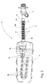
Figure 2 shows an underside view of the detergent drawer flush circuit inFigure 1 . -
Number 1 inFigure 1 indicates as a whole a preferably, though not necessarily, front-loaded home washing machine, which substantially comprises a preferably, though not necessarily, parallelepiped-shaped casing 2; and adetergent drawer 3 housed removably inside a seat on the front face ofcasing 2, and having at least one compartment for a given amount of detergent and/or softener for use in the wash cycle. -
Washing machine 1 also comprises adrawer flush circuit 4, which, on command, feeds a given amount of water into the compartment ofdetergent drawer 3 to flush the detergent or softener out of the compartment in controlled manner and down into acatch tray 5 located directly beneathdetergent drawer 3 and communicating with the wash tub (not shown) of the machine. - More specifically, with reference to
Figures 1 and2 ,drawer flush circuit 4 comprises awater supply pipe 6, which terminates directly overdetergent drawer 3, and is designed at the end to feed a dense shower of water droplets by gravity into the compartment ofdetergent drawer 3 underneath; and at least one electrically controlled on-offvalve 7 interposed betweenwater supply pipe 6 and the water mains 8 of the building in which the washing machine is installed, to regulate pressurized-water flow to the end ofwater supply pipe 6, so as to sprinkle the compartment ofdetergent drawer 3 on command. - In the example shown, electrically controlled on-off
valve 7 is a conventional controlled-open-close solenoid valve 7. -
Water supply pipe 6 comprises asprinkler head 9 located directly overdetergent drawer 3, to substantially cover the compartment ofdetergent drawer 3, and designed to form internally acoil 9a, which is located over the compartment ofdetergent drawer 3 and has a number of discharge nozzles for gravity feeding a dense shower of water droplets into the compartment underneath; and a connectingpipe 10, which connects the outlet of on-offvalve 7 to the inlet ofcoil 9a ofsprinkler head 9, and has at least one highly flexiblecorrugated portion 10a. - With reference to
Figures 1 and2 ,sprinkler head 9 also comprises, at the inlet to coil 9a, a pressure-balancing chamber orcavity 9b, through which the water from connectingpipe 10 flows, and which communicates directly with the outside to bring the incoming water intocoil 9a rapidly to the same pressure as the surrounding air (i.e. to atmospheric pressure). - Unlike known washing machines, however,
water supply pipe 6 is defined by a single blow-molded hollow part made of plastic material, and in whichsprinkler head 9 and connectingpipe 10 are formed simultaneously, and the portion ofsupply pipe 6 corresponding to connectingpipe 10 also has two projectinglongitudinal tabs 11, which project from opposite sides of connectingpipe 10, preferably, though not necessarily, along the whole length of the connecting pipe, or at least along the whole length ofcorrugated portion 10a of the connecting pipe, and are of a nominal width of over 2 millimetres. - In other words,
coil 9a, pressure-balancingcavity 9b, and connectingpipe 10 for connection to on-offvalve 7 are formed in one piece from a single hose of plastic material by a blow molding process which also simultaneously forms twolongitudinal tabs 11 of over 2 millimetres in width along at least the two opposite sides ofcorrugated portion 10a of connectingpipe 10. - In the example shown, the two projecting
longitudinal tabs 11 project from the sides of connectingpipe 10 along the whole length of connectingpipe 10, and are of a nominal width of over 3 millimetres. - Operation of
washing machine 1 will be clear from the above description, with no further explanation required. - As regards
drawer flush circuit 4 and, more specifically,water supply pipe 6, on the other hand, tests show that the twolongitudinal tabs 11, of over 2 mm in width, on the portion ofsupply pipe 6 forming connectingpipe 10, or at least thecorrugated portion 10a of connectingpipe 10, provide for firmly sticking the portions of the plastic hose not required to form connectingpipe 10, thus ensuring sufficient pressure resistance to withstand any pressure peaks caused by clogging of connectingpipe 10 immediately upstream from pressure-balancingcavity 9b. - The advantages of a one-piece
water supply pipe 6 are obvious :drawer flush circuit 4 is cheaper to produce and faster to install on the washing machine, thus greatly reducing the manufacturing cost ofwashing machine 1. - Clearly, changes may be made to washing
machine 1 anddrawer flush circuit 4 without, however, departing from the scope of the present invention. - For example,
detergent drawer 3 may be divided into a number of compartments for detergent and/or softener for use in the wash cycle, anddrawer flush circuit 4 feeds water selectively and independently into each drawer compartment to flush the detergent or similar out of the compartment in controlled manner. - In which case,
sprinkler head 9 ofpipe 6 comprises a number ofcoils 9a, each of which is located over a respective compartment ofdetergent drawer 3, and has a number of nozzles for gravity feeding a dense shower of water droplets into the compartment underneath; anddrawer flush circuit 4 comprises a number of on-offvalves 7, each for regulating pressurized-water flow to arespective coil 9a ofsprinkler head 9. - More specifically, in this variation,
water supply pipe 6 comprises a number of connectingpipes 10, each connecting the outlet of a respective on-offvalve 7 to the inlet of acorresponding coil 9a ofsprinkler head 9. - Obviously, in this case, too, the connecting
pipes 10 are formed in one piece withsprinkler head 9, and have two projectinglongitudinal tabs 11, of over 2 millimetres nominal width, on either side; andsprinkler 9 has a respective pressure-balancing chamber orcavity 9b at the inlet of eachcoil 9a.
Claims (7)
- A home washing machine (1) comprising an open-topped detergent container (3) having at least one compartment for detergent or similar for use in the wash cycle; and a container flush circuit (4) which, on command, feeds water into the compartment of said detergent container (3) to flush the detergent or similar out of the compartment in controlled manner; the container flush circuit (4) comprising a water supply pipe (6), which terminates directly over said detergent container (3) and has an end portion designed to sprinkle water into the compartment of the detergent container (3) underneath, and at least one controlled-open-close on-off valve (7) for regulating pressurized-water flow to the end portion of said water supply pipe (6) to sprinkle said compartment on command; the water supply pipe (6) comprising a sprinkler head (9) located directly over the detergent container (3) and designed to sprinkle water into the compartment of the detergent container (3) underneath, and a connecting pipe (10) having at least one flexible intermediate corrugated portion (10a), and connecting said on-off valve (7) to said sprinkler head (9); the home washing machine (1) being characterized in that the water supply pipe (6) is formed in one piece with said sprinkler head (9) and said connecting pipe (10), and comprises two longitudinal tabs (11) projecting on opposite sides of the connecting pipe (10), at least along the whole length of the flexible intermediate portion (10a) of the connecting pipe.
- A washing machine as claimed in Claim 1,
characterized in that said water supply pipe (6) is made of plastic material and blow molded in one piece. - A washing machine as claimed in Claim 1 or 2, characterized in that said sprinkler head (9) is designed to form at least one coil (9a) located over said at least one compartment of the detergent container (3) and having a number of nozzles for gravity sprinkling water into the compartment underneath; and at least one pressure-balancing chamber (9b), which is interposed between the coil (9a) and the connecting pipe (10), is fed through with the water from said connecting pipe (10), and communicates directly with the outside to bring the pressure of the incoming water to said coil (9a) rapidly to the same pressure as the surrounding air.
- A washing machine as claimed in any one of the foregoing Claims, characterized in that said longitudinal tabs (11) are of a nominal width of over 2 millimetres.
- A washing machine as claimed in any one of the foregoing Claims, characterized in that said detergent container (3) comprises a number of compartments for detergent or similar for use in the wash cycle; and said container flush circuit (4) feeds water, on command, into each compartment of said detergent container (3) selectively and independently of the others.
- A washing machine as claimed in Claim 5,
characterized in that said sprinkler head (9) is divided into a number of independent coils (9a), each located over a respective compartment of said detergent container (3), and having a number of nozzles for gravity sprinkling water into the compartment underneath; and said container flush circuit (4) comprises a number of controlled-open-close on-off valves (7), each for regulating pressurized-water flow to a respective coil (9a) of the sprinkler head (9), to sprinkle the respective compartment on command. - A washing machine as claimed in any one of the foregoing Claims, characterized in that said detergent container (3) is a detergent drawer (3) housed removably in a seat formed in the casing (2) of said washing machine (1).
Priority Applications (3)
| Application Number | Priority Date | Filing Date | Title |
|---|---|---|---|
| EP08150399A EP2080831B1 (en) | 2008-01-18 | 2008-01-18 | Home washing machine |
| AT08150399T ATE554216T1 (en) | 2008-01-18 | 2008-01-18 | HOUSEHOLD WASHING MACHINE |
| PCT/EP2008/010732 WO2009089887A1 (en) | 2008-01-18 | 2008-12-17 | Home washing machine |
Applications Claiming Priority (1)
| Application Number | Priority Date | Filing Date | Title |
|---|---|---|---|
| EP08150399A EP2080831B1 (en) | 2008-01-18 | 2008-01-18 | Home washing machine |
Publications (2)
| Publication Number | Publication Date |
|---|---|
| EP2080831A1 true EP2080831A1 (en) | 2009-07-22 |
| EP2080831B1 EP2080831B1 (en) | 2012-04-18 |
Family
ID=39619348
Family Applications (1)
| Application Number | Title | Priority Date | Filing Date |
|---|---|---|---|
| EP08150399A Not-in-force EP2080831B1 (en) | 2008-01-18 | 2008-01-18 | Home washing machine |
Country Status (3)
| Country | Link |
|---|---|
| EP (1) | EP2080831B1 (en) |
| AT (1) | ATE554216T1 (en) |
| WO (1) | WO2009089887A1 (en) |
Cited By (2)
| Publication number | Priority date | Publication date | Assignee | Title |
|---|---|---|---|---|
| WO2011047451A1 (en) * | 2009-10-21 | 2011-04-28 | Whirpool S.A. | Cleaning supply dispenser for clothes washing machines |
| WO2015065301A1 (en) * | 2013-11-01 | 2015-05-07 | Arcelik Anonim Sirketi | A washing machine comprising a cleaning agent dispenser |
Citations (3)
| Publication number | Priority date | Publication date | Assignee | Title |
|---|---|---|---|---|
| DE1610147A1 (en) * | 1967-06-09 | 1970-11-19 | Siemens Elektrogeraete Gmbh | Household machine with automatic addition of detergent and detergent |
| DE8603895U1 (en) * | 1986-02-14 | 1986-05-15 | Bauknecht Hausgeräte GmbH, 70565 Stuttgart | Washing machine with a device to prevent water damage |
| EP0688895A1 (en) * | 1994-06-20 | 1995-12-27 | TECNOPLASTICA PREALPINA S.p.A. | A distribution valve-mixing draw assembly for the selective supply of detergents or other substances to the washing machine or the like |
-
2008
- 2008-01-18 AT AT08150399T patent/ATE554216T1/en active
- 2008-01-18 EP EP08150399A patent/EP2080831B1/en not_active Not-in-force
- 2008-12-17 WO PCT/EP2008/010732 patent/WO2009089887A1/en not_active Ceased
Patent Citations (3)
| Publication number | Priority date | Publication date | Assignee | Title |
|---|---|---|---|---|
| DE1610147A1 (en) * | 1967-06-09 | 1970-11-19 | Siemens Elektrogeraete Gmbh | Household machine with automatic addition of detergent and detergent |
| DE8603895U1 (en) * | 1986-02-14 | 1986-05-15 | Bauknecht Hausgeräte GmbH, 70565 Stuttgart | Washing machine with a device to prevent water damage |
| EP0688895A1 (en) * | 1994-06-20 | 1995-12-27 | TECNOPLASTICA PREALPINA S.p.A. | A distribution valve-mixing draw assembly for the selective supply of detergents or other substances to the washing machine or the like |
Cited By (2)
| Publication number | Priority date | Publication date | Assignee | Title |
|---|---|---|---|---|
| WO2011047451A1 (en) * | 2009-10-21 | 2011-04-28 | Whirpool S.A. | Cleaning supply dispenser for clothes washing machines |
| WO2015065301A1 (en) * | 2013-11-01 | 2015-05-07 | Arcelik Anonim Sirketi | A washing machine comprising a cleaning agent dispenser |
Also Published As
| Publication number | Publication date |
|---|---|
| ATE554216T1 (en) | 2012-05-15 |
| WO2009089887A1 (en) | 2009-07-23 |
| EP2080831B1 (en) | 2012-04-18 |
Similar Documents
| Publication | Publication Date | Title |
|---|---|---|
| EP1319360B1 (en) | Domestic dishwasher with a front loading door having a recessed panel and a detergent measurer/dispenser supported by the upper rack | |
| ITMI20010972A1 (en) | FILTER HOLDER OF A COFFEE STAIN AND PROCEDURE TO PRODUCE A COFFEE BEVERAGE | |
| KR100335475B1 (en) | Iron and steam brush for business use | |
| EP2859820B1 (en) | Self-cleaning milk foaming device | |
| CN101437662B (en) | Barrel gas exhaust device | |
| EP2080831B1 (en) | Home washing machine | |
| KR200417397Y1 (en) | Wrinkle remover of car seat | |
| CN1953688A (en) | Device for foaming milk, comprising external suction equipment | |
| JP2017031601A (en) | Sanitary washing device and toilet device | |
| JP2007529337A (en) | Cleaning method of ink chamber of printing unit, cleaning system thereof, and cleaning nozzle in cleaning system | |
| KR20180103383A (en) | Dishwasher and Controlling method therefor | |
| CN106436190B (en) | Automatic feeding system of washing machine and washing machine with automatic feeding system | |
| CN112411154B (en) | Household appliance comprising a tank for generating pressurized steam | |
| JP2011024943A (en) | Automatic cleaning apparatus for bathtub | |
| CN102628293A (en) | Health washing device | |
| KR101231844B1 (en) | Hand drying apparatus | |
| EP2216180A3 (en) | A system for supplying ink to a printing machine | |
| KR100717472B1 (en) | Dishwasher and its water supply method | |
| KR100821680B1 (en) | Bidet with draw-out dry nozzle | |
| CN106400406A (en) | Automatic dispensing system of washing machine and washing machine with same | |
| JP2016098632A (en) | Toilet bowl device | |
| JP2016166452A (en) | Hot water washing toilet seat device | |
| CN221588898U (en) | Cleaning apparatus | |
| KR200456912Y1 (en) | Hot water circulation system | |
| JP2010240150A (en) | Heating device for steam apparatus |
Legal Events
| Date | Code | Title | Description |
|---|---|---|---|
| PUAI | Public reference made under article 153(3) epc to a published international application that has entered the european phase |
Free format text: ORIGINAL CODE: 0009012 |
|
| AK | Designated contracting states |
Kind code of ref document: A1 Designated state(s): AT BE BG CH CY CZ DE DK EE ES FI FR GB GR HR HU IE IS IT LI LT LU LV MC MT NL NO PL PT RO SE SI SK TR |
|
| AX | Request for extension of the european patent |
Extension state: AL BA MK RS |
|
| 17P | Request for examination filed |
Effective date: 20091222 |
|
| AKX | Designation fees paid |
Designated state(s): AT BE BG CH CY CZ DE DK EE ES FI FR GB GR HR HU IE IS IT LI LT LU LV MC MT NL NO PL PT RO SE SI SK TR |
|
| RAP1 | Party data changed (applicant data changed or rights of an application transferred) |
Owner name: ELECTROLUX HOME PRODUCTS CORPORATION N.V. |
|
| RAP1 | Party data changed (applicant data changed or rights of an application transferred) |
Owner name: ELECTROLUX HOME PRODUCTS CORPORATION N.V. |
|
| GRAP | Despatch of communication of intention to grant a patent |
Free format text: ORIGINAL CODE: EPIDOSNIGR1 |
|
| GRAS | Grant fee paid |
Free format text: ORIGINAL CODE: EPIDOSNIGR3 |
|
| GRAA | (expected) grant |
Free format text: ORIGINAL CODE: 0009210 |
|
| AK | Designated contracting states |
Kind code of ref document: B1 Designated state(s): AT BE BG CH CY CZ DE DK EE ES FI FR GB GR HR HU IE IS IT LI LT LU LV MC MT NL NO PL PT RO SE SI SK TR |
|
| REG | Reference to a national code |
Ref country code: GB Ref legal event code: FG4D |
|
| REG | Reference to a national code |
Ref country code: CH Ref legal event code: EP |
|
| REG | Reference to a national code |
Ref country code: IE Ref legal event code: FG4D |
|
| REG | Reference to a national code |
Ref country code: AT Ref legal event code: REF Ref document number: 554216 Country of ref document: AT Kind code of ref document: T Effective date: 20120515 |
|
| REG | Reference to a national code |
Ref country code: DE Ref legal event code: R096 Ref document number: 602008014858 Country of ref document: DE Effective date: 20120614 |
|
| REG | Reference to a national code |
Ref country code: NL Ref legal event code: VDEP Effective date: 20120418 |
|
| REG | Reference to a national code |
Ref country code: AT Ref legal event code: MK05 Ref document number: 554216 Country of ref document: AT Kind code of ref document: T Effective date: 20120418 |
|
| LTIE | Lt: invalidation of european patent or patent extension |
Effective date: 20120418 |
|
| PG25 | Lapsed in a contracting state [announced via postgrant information from national office to epo] |
Ref country code: PL Free format text: LAPSE BECAUSE OF FAILURE TO SUBMIT A TRANSLATION OF THE DESCRIPTION OR TO PAY THE FEE WITHIN THE PRESCRIBED TIME-LIMIT Effective date: 20120418 Ref country code: FI Free format text: LAPSE BECAUSE OF FAILURE TO SUBMIT A TRANSLATION OF THE DESCRIPTION OR TO PAY THE FEE WITHIN THE PRESCRIBED TIME-LIMIT Effective date: 20120418 Ref country code: SE Free format text: LAPSE BECAUSE OF FAILURE TO SUBMIT A TRANSLATION OF THE DESCRIPTION OR TO PAY THE FEE WITHIN THE PRESCRIBED TIME-LIMIT Effective date: 20120418 Ref country code: CY Free format text: LAPSE BECAUSE OF FAILURE TO SUBMIT A TRANSLATION OF THE DESCRIPTION OR TO PAY THE FEE WITHIN THE PRESCRIBED TIME-LIMIT Effective date: 20120418 Ref country code: LT Free format text: LAPSE BECAUSE OF FAILURE TO SUBMIT A TRANSLATION OF THE DESCRIPTION OR TO PAY THE FEE WITHIN THE PRESCRIBED TIME-LIMIT Effective date: 20120418 Ref country code: NO Free format text: LAPSE BECAUSE OF FAILURE TO SUBMIT A TRANSLATION OF THE DESCRIPTION OR TO PAY THE FEE WITHIN THE PRESCRIBED TIME-LIMIT Effective date: 20120718 Ref country code: IS Free format text: LAPSE BECAUSE OF FAILURE TO SUBMIT A TRANSLATION OF THE DESCRIPTION OR TO PAY THE FEE WITHIN THE PRESCRIBED TIME-LIMIT Effective date: 20120818 |
|
| PG25 | Lapsed in a contracting state [announced via postgrant information from national office to epo] |
Ref country code: HR Free format text: LAPSE BECAUSE OF FAILURE TO SUBMIT A TRANSLATION OF THE DESCRIPTION OR TO PAY THE FEE WITHIN THE PRESCRIBED TIME-LIMIT Effective date: 20120418 Ref country code: PT Free format text: LAPSE BECAUSE OF FAILURE TO SUBMIT A TRANSLATION OF THE DESCRIPTION OR TO PAY THE FEE WITHIN THE PRESCRIBED TIME-LIMIT Effective date: 20120820 Ref country code: GR Free format text: LAPSE BECAUSE OF FAILURE TO SUBMIT A TRANSLATION OF THE DESCRIPTION OR TO PAY THE FEE WITHIN THE PRESCRIBED TIME-LIMIT Effective date: 20120719 Ref country code: SI Free format text: LAPSE BECAUSE OF FAILURE TO SUBMIT A TRANSLATION OF THE DESCRIPTION OR TO PAY THE FEE WITHIN THE PRESCRIBED TIME-LIMIT Effective date: 20120418 Ref country code: LV Free format text: LAPSE BECAUSE OF FAILURE TO SUBMIT A TRANSLATION OF THE DESCRIPTION OR TO PAY THE FEE WITHIN THE PRESCRIBED TIME-LIMIT Effective date: 20120418 |
|
| PG25 | Lapsed in a contracting state [announced via postgrant information from national office to epo] |
Ref country code: BE Free format text: LAPSE BECAUSE OF FAILURE TO SUBMIT A TRANSLATION OF THE DESCRIPTION OR TO PAY THE FEE WITHIN THE PRESCRIBED TIME-LIMIT Effective date: 20120418 |
|
| PG25 | Lapsed in a contracting state [announced via postgrant information from national office to epo] |
Ref country code: CZ Free format text: LAPSE BECAUSE OF FAILURE TO SUBMIT A TRANSLATION OF THE DESCRIPTION OR TO PAY THE FEE WITHIN THE PRESCRIBED TIME-LIMIT Effective date: 20120418 Ref country code: SK Free format text: LAPSE BECAUSE OF FAILURE TO SUBMIT A TRANSLATION OF THE DESCRIPTION OR TO PAY THE FEE WITHIN THE PRESCRIBED TIME-LIMIT Effective date: 20120418 Ref country code: RO Free format text: LAPSE BECAUSE OF FAILURE TO SUBMIT A TRANSLATION OF THE DESCRIPTION OR TO PAY THE FEE WITHIN THE PRESCRIBED TIME-LIMIT Effective date: 20120418 Ref country code: DK Free format text: LAPSE BECAUSE OF FAILURE TO SUBMIT A TRANSLATION OF THE DESCRIPTION OR TO PAY THE FEE WITHIN THE PRESCRIBED TIME-LIMIT Effective date: 20120418 Ref country code: AT Free format text: LAPSE BECAUSE OF FAILURE TO SUBMIT A TRANSLATION OF THE DESCRIPTION OR TO PAY THE FEE WITHIN THE PRESCRIBED TIME-LIMIT Effective date: 20120418 Ref country code: NL Free format text: LAPSE BECAUSE OF FAILURE TO SUBMIT A TRANSLATION OF THE DESCRIPTION OR TO PAY THE FEE WITHIN THE PRESCRIBED TIME-LIMIT Effective date: 20120418 Ref country code: EE Free format text: LAPSE BECAUSE OF FAILURE TO SUBMIT A TRANSLATION OF THE DESCRIPTION OR TO PAY THE FEE WITHIN THE PRESCRIBED TIME-LIMIT Effective date: 20120418 |
|
| PLBE | No opposition filed within time limit |
Free format text: ORIGINAL CODE: 0009261 |
|
| STAA | Information on the status of an ep patent application or granted ep patent |
Free format text: STATUS: NO OPPOSITION FILED WITHIN TIME LIMIT |
|
| 26N | No opposition filed |
Effective date: 20130121 |
|
| PG25 | Lapsed in a contracting state [announced via postgrant information from national office to epo] |
Ref country code: ES Free format text: LAPSE BECAUSE OF FAILURE TO SUBMIT A TRANSLATION OF THE DESCRIPTION OR TO PAY THE FEE WITHIN THE PRESCRIBED TIME-LIMIT Effective date: 20120729 |
|
| PGFP | Annual fee paid to national office [announced via postgrant information from national office to epo] |
Ref country code: DE Payment date: 20130122 Year of fee payment: 6 Ref country code: FR Payment date: 20130213 Year of fee payment: 6 Ref country code: GB Payment date: 20130122 Year of fee payment: 6 |
|
| REG | Reference to a national code |
Ref country code: DE Ref legal event code: R097 Ref document number: 602008014858 Country of ref document: DE Effective date: 20130121 |
|
| PG25 | Lapsed in a contracting state [announced via postgrant information from national office to epo] |
Ref country code: BG Free format text: LAPSE BECAUSE OF FAILURE TO SUBMIT A TRANSLATION OF THE DESCRIPTION OR TO PAY THE FEE WITHIN THE PRESCRIBED TIME-LIMIT Effective date: 20120718 |
|
| PG25 | Lapsed in a contracting state [announced via postgrant information from national office to epo] |
Ref country code: MC Free format text: LAPSE BECAUSE OF NON-PAYMENT OF DUE FEES Effective date: 20130131 |
|
| REG | Reference to a national code |
Ref country code: CH Ref legal event code: PL |
|
| REG | Reference to a national code |
Ref country code: IE Ref legal event code: MM4A |
|
| PG25 | Lapsed in a contracting state [announced via postgrant information from national office to epo] |
Ref country code: LI Free format text: LAPSE BECAUSE OF NON-PAYMENT OF DUE FEES Effective date: 20130131 Ref country code: CH Free format text: LAPSE BECAUSE OF NON-PAYMENT OF DUE FEES Effective date: 20130131 |
|
| PG25 | Lapsed in a contracting state [announced via postgrant information from national office to epo] |
Ref country code: IE Free format text: LAPSE BECAUSE OF NON-PAYMENT OF DUE FEES Effective date: 20130118 |
|
| PG25 | Lapsed in a contracting state [announced via postgrant information from national office to epo] |
Ref country code: MT Free format text: LAPSE BECAUSE OF FAILURE TO SUBMIT A TRANSLATION OF THE DESCRIPTION OR TO PAY THE FEE WITHIN THE PRESCRIBED TIME-LIMIT Effective date: 20120418 |
|
| REG | Reference to a national code |
Ref country code: DE Ref legal event code: R119 Ref document number: 602008014858 Country of ref document: DE |
|
| GBPC | Gb: european patent ceased through non-payment of renewal fee |
Effective date: 20140118 |
|
| REG | Reference to a national code |
Ref country code: DE Ref legal event code: R119 Ref document number: 602008014858 Country of ref document: DE Effective date: 20140801 |
|
| PG25 | Lapsed in a contracting state [announced via postgrant information from national office to epo] |
Ref country code: DE Free format text: LAPSE BECAUSE OF NON-PAYMENT OF DUE FEES Effective date: 20140801 |
|
| REG | Reference to a national code |
Ref country code: FR Ref legal event code: ST Effective date: 20140930 |
|
| PG25 | Lapsed in a contracting state [announced via postgrant information from national office to epo] |
Ref country code: FR Free format text: LAPSE BECAUSE OF NON-PAYMENT OF DUE FEES Effective date: 20140131 Ref country code: GB Free format text: LAPSE BECAUSE OF NON-PAYMENT OF DUE FEES Effective date: 20140118 |
|
| PG25 | Lapsed in a contracting state [announced via postgrant information from national office to epo] |
Ref country code: TR Free format text: LAPSE BECAUSE OF FAILURE TO SUBMIT A TRANSLATION OF THE DESCRIPTION OR TO PAY THE FEE WITHIN THE PRESCRIBED TIME-LIMIT Effective date: 20120418 |
|
| PG25 | Lapsed in a contracting state [announced via postgrant information from national office to epo] |
Ref country code: HU Free format text: LAPSE BECAUSE OF FAILURE TO SUBMIT A TRANSLATION OF THE DESCRIPTION OR TO PAY THE FEE WITHIN THE PRESCRIBED TIME-LIMIT; INVALID AB INITIO Effective date: 20080118 Ref country code: LU Free format text: LAPSE BECAUSE OF NON-PAYMENT OF DUE FEES Effective date: 20130118 |
|
| PG25 | Lapsed in a contracting state [announced via postgrant information from national office to epo] |
Ref country code: IT Free format text: LAPSE BECAUSE OF NON-PAYMENT OF DUE FEES Effective date: 20140118 |