EP2080704A1 - Box body - Google Patents
Box body Download PDFInfo
- Publication number
- EP2080704A1 EP2080704A1 EP07830688A EP07830688A EP2080704A1 EP 2080704 A1 EP2080704 A1 EP 2080704A1 EP 07830688 A EP07830688 A EP 07830688A EP 07830688 A EP07830688 A EP 07830688A EP 2080704 A1 EP2080704 A1 EP 2080704A1
- Authority
- EP
- European Patent Office
- Prior art keywords
- container
- constituting
- lid
- folding
- folding surface
- Prior art date
- Legal status (The legal status is an assumption and is not a legal conclusion. Google has not performed a legal analysis and makes no representation as to the accuracy of the status listed.)
- Withdrawn
Links
Images









Classifications
-
- B—PERFORMING OPERATIONS; TRANSPORTING
- B65—CONVEYING; PACKING; STORING; HANDLING THIN OR FILAMENTARY MATERIAL
- B65D—CONTAINERS FOR STORAGE OR TRANSPORT OF ARTICLES OR MATERIALS, e.g. BAGS, BARRELS, BOTTLES, BOXES, CANS, CARTONS, CRATES, DRUMS, JARS, TANKS, HOPPERS, FORWARDING CONTAINERS; ACCESSORIES, CLOSURES, OR FITTINGS THEREFOR; PACKAGING ELEMENTS; PACKAGES
- B65D5/00—Rigid or semi-rigid containers of polygonal cross-section, e.g. boxes, cartons or trays, formed by folding or erecting one or more blanks made of paper
- B65D5/02—Rigid or semi-rigid containers of polygonal cross-section, e.g. boxes, cartons or trays, formed by folding or erecting one or more blanks made of paper by folding or erecting a single blank to form a tubular body with or without subsequent folding operations, or the addition of separate elements, to close the ends of the body
- B65D5/0227—Rigid or semi-rigid containers of polygonal cross-section, e.g. boxes, cartons or trays, formed by folding or erecting one or more blanks made of paper by folding or erecting a single blank to form a tubular body with or without subsequent folding operations, or the addition of separate elements, to close the ends of the body with end closures formed by inward folding of flaps and securing them by heat-sealing, by applying adhesive to the flaps or by staples
-
- B—PERFORMING OPERATIONS; TRANSPORTING
- B65—CONVEYING; PACKING; STORING; HANDLING THIN OR FILAMENTARY MATERIAL
- B65D—CONTAINERS FOR STORAGE OR TRANSPORT OF ARTICLES OR MATERIALS, e.g. BAGS, BARRELS, BOTTLES, BOXES, CANS, CARTONS, CRATES, DRUMS, JARS, TANKS, HOPPERS, FORWARDING CONTAINERS; ACCESSORIES, CLOSURES, OR FITTINGS THEREFOR; PACKAGING ELEMENTS; PACKAGES
- B65D5/00—Rigid or semi-rigid containers of polygonal cross-section, e.g. boxes, cartons or trays, formed by folding or erecting one or more blanks made of paper
- B65D5/02—Rigid or semi-rigid containers of polygonal cross-section, e.g. boxes, cartons or trays, formed by folding or erecting one or more blanks made of paper by folding or erecting a single blank to form a tubular body with or without subsequent folding operations, or the addition of separate elements, to close the ends of the body
- B65D5/10—Rigid or semi-rigid containers of polygonal cross-section, e.g. boxes, cartons or trays, formed by folding or erecting one or more blanks made of paper by folding or erecting a single blank to form a tubular body with or without subsequent folding operations, or the addition of separate elements, to close the ends of the body with end closures formed by inward-folding of self-locking flaps hinged to tubular body
- B65D5/103—Rigid or semi-rigid containers of polygonal cross-section, e.g. boxes, cartons or trays, formed by folding or erecting one or more blanks made of paper by folding or erecting a single blank to form a tubular body with or without subsequent folding operations, or the addition of separate elements, to close the ends of the body with end closures formed by inward-folding of self-locking flaps hinged to tubular body one of the self-locking flaps having a tongue engaging into an opening of an opposite flap
- B65D5/106—Rigid or semi-rigid containers of polygonal cross-section, e.g. boxes, cartons or trays, formed by folding or erecting one or more blanks made of paper by folding or erecting a single blank to form a tubular body with or without subsequent folding operations, or the addition of separate elements, to close the ends of the body with end closures formed by inward-folding of self-locking flaps hinged to tubular body one of the self-locking flaps having a tongue engaging into an opening of an opposite flap the opening being a slot
-
- B—PERFORMING OPERATIONS; TRANSPORTING
- B65—CONVEYING; PACKING; STORING; HANDLING THIN OR FILAMENTARY MATERIAL
- B65D—CONTAINERS FOR STORAGE OR TRANSPORT OF ARTICLES OR MATERIALS, e.g. BAGS, BARRELS, BOTTLES, BOXES, CANS, CARTONS, CRATES, DRUMS, JARS, TANKS, HOPPERS, FORWARDING CONTAINERS; ACCESSORIES, CLOSURES, OR FITTINGS THEREFOR; PACKAGING ELEMENTS; PACKAGES
- B65D5/00—Rigid or semi-rigid containers of polygonal cross-section, e.g. boxes, cartons or trays, formed by folding or erecting one or more blanks made of paper
- B65D5/42—Details of containers or of foldable or erectable container blanks
- B65D5/4204—Inspection openings or windows
-
- B—PERFORMING OPERATIONS; TRANSPORTING
- B65—CONVEYING; PACKING; STORING; HANDLING THIN OR FILAMENTARY MATERIAL
- B65D—CONTAINERS FOR STORAGE OR TRANSPORT OF ARTICLES OR MATERIALS, e.g. BAGS, BARRELS, BOTTLES, BOXES, CANS, CARTONS, CRATES, DRUMS, JARS, TANKS, HOPPERS, FORWARDING CONTAINERS; ACCESSORIES, CLOSURES, OR FITTINGS THEREFOR; PACKAGING ELEMENTS; PACKAGES
- B65D5/00—Rigid or semi-rigid containers of polygonal cross-section, e.g. boxes, cartons or trays, formed by folding or erecting one or more blanks made of paper
- B65D5/42—Details of containers or of foldable or erectable container blanks
- B65D5/44—Integral, inserted or attached portions forming internal or external fittings
- B65D5/46—Handles
- B65D5/46072—Handles integral with the container
- B65D5/46088—Handles integral with the container formed by extensions of closure flaps, by closure flaps or by extensions of side flaps of a container formed by folding a blank to form a tubular body
-
- B—PERFORMING OPERATIONS; TRANSPORTING
- B65—CONVEYING; PACKING; STORING; HANDLING THIN OR FILAMENTARY MATERIAL
- B65D—CONTAINERS FOR STORAGE OR TRANSPORT OF ARTICLES OR MATERIALS, e.g. BAGS, BARRELS, BOTTLES, BOXES, CANS, CARTONS, CRATES, DRUMS, JARS, TANKS, HOPPERS, FORWARDING CONTAINERS; ACCESSORIES, CLOSURES, OR FITTINGS THEREFOR; PACKAGING ELEMENTS; PACKAGES
- B65D5/00—Rigid or semi-rigid containers of polygonal cross-section, e.g. boxes, cartons or trays, formed by folding or erecting one or more blanks made of paper
- B65D5/42—Details of containers or of foldable or erectable container blanks
- B65D5/72—Contents-dispensing means
- B65D5/726—Means for discharging contents through the bottom of containers
Definitions
- the present invention relates to a container, which is preferably applied to a carton containing a plurality of small sized articles, to be handled, such as PET bottles, cans, cigarettes, pencils, and filled parts and a package box for various kinds of electric equipment or the like. More particularly, it relates to a container, one of container-constituting surfaces of which has an opening with a predetermined size, which is provided with five container-constituting portions that make mountain or valley fold, the container-constituting portions having predetermined shapes and sizes.
- the container is constituted so that a lid-closing part and an intermediate lid-pushing part are successively inserted into a slit of a first lid-constituting part, the intermediate lid-pushing part covers the first lid-constituting part and a second lid-constituting part covers the intermediate lid-pushing part so that the lid-closing part wraps a container-constituting part, and the other lid-closing part is engaged with the container-constituting portion with the other lid-closing part wrapping the lid-closing part.
- the container By configuring the container so as to be so, it is possible to close the opening doubly by the first and second lid-constituting parts and the intermediate lid-pushing part as well as it is possible to open the opening only by pulling the lid-constituting parts and the lid-closing parts from a side of the container-constituting portion to a side of the container-constituting surface.
- a plurality of small sized articles, to be handled such as PET bottles, cans, cigarettes, pencils, and filled parts has been often distributed with a desired carton containing them or various kinds of electric equipment or the like have been often distributed with a package box using corrugated cardboard containing them.
- a carton or a package box is made by performing the taking of measurements on carton material or box material with a predetermined size, creating a development of the container, cutting notches into predetermined portions of the developed container and erecting the container by making mountain or valley fold on the carton material or box material.
- a packing case for supplement of article and a method of supplementing the article for a vending machine using the same have been disclosed in Japanese Patent Application Publication No. Hei05-04640 .
- the articles are contained in the container so that they are aligned in a longitudinal direction thereof.
- the articles are bound by a band for fixing the articles.
- the band is fixed into the container at forward and rearward ends thereof.
- the container is set onto the vending machine with a forward end thereof being positioned at a downward direction. It is constituted that after setting, a perforated portion is separated so that the forward end is opened, and then, the band for fixing the articles is disengaged.
- a package box has been disclosed in Japanese Patent Application Publication No. 2001-02057 .
- This package box has an outer container with a predetermined size and a triangular opening in an outer container configuration surface.
- an inner container is provided within the outer container.
- the inner container uses corrugated cardboard vertically.
- a lid-constituting portion is provided so as to extend from side surfaces of the outer container to an upper surface thereof continuously and is closed by a string on a predetermined position on the upper surface of the outer container.
- it is configured that a stripe pattern of the corrugated cardboard of the inner container is exposed from the triangular opening.
- a package with a dispenser has been disclosed in Japanese Patent Application Publication No. 2005-53555 .
- a carton having the dispenser at its forward end portion is provided and in the dispenser, a separation part is defined by cutting carton-constituting portion that is constituted of side walls, an upper surface and a bottom surface of the forward end portion of the carton-constituting portion into one with a predetermined size and an opening is obtained by folding a part by which a side of this separation part is common in the carton-constituting portion and pulling out the separation part to a side of the carton-constituting portion.
- the opening when such an opened package is held so that its posture is directed to a vertical direction, the opening is positioned at a low position.
- the opening has such a size that allows a predetermined article contained in the package to be removed therefrom.
- a carton having the dispenser at its forward end portion is provided and in the dispenser, a displaceable portion is defined by cutting carton-constituting portion that is constituted of side walls, an upper surface and a bottom surface of the forward end portion of the carton-constituting portion into one with a predetermined size and an opening is obtained by folding a part by which a side of this displaceable portion is common in the carton-constituting portion and tearing up the displaceable portion near a user.
- the opening when such an opened package is held so that its posture is directed to a horizontal direction, the opening is positioned at an upper position.
- the opening has such a size that allows a predetermined article contained in the carton to be removed therefrom.
- the dispenser is formed by cutting carton-constituting portion that is constituted of side walls, an upper surface and a bottom surface of the forward end portion of the carton-constituting surfaces into one with a predetermined size.
- the container is installed into a vending machine or an automatic machine such as a binding machine and various kinds of power tools and the articles to be contained therein is provided (supplied) but a filling space is blocked in three directions when it has a dispenser configuration like ones disclosed in Japanese Patent Application Publication No. Hei05-04640 , Japanese Patent Application Publication No. 2001-02057 , Japanese Patent Application Publication No. 2005-53555 and Japanese Patent Application Publication No. 2005-53584 , there is such a problem that any workability is deteriorated because an operator's hand does not reach the right and left side surfaces and a rear surface of the filling space.
- a container according to the present invention in which one of container-constituting surfaces forms an opening with a predetermined size is characterized in that if two constituting surfaces standing facing each other across the opening are supposed as first and second constituting surfaces, it is provided with a first folding surface that makes a mountain fold on the first constituting surface, the first folding surface having a length extending beyond the opening, a second folding surface that makes a valley fold on the first folding surface, a third folding surface that makes a valley fold on the second folding surface, a fourth folding surface that makes a mountain fold on the second constituting surface, the fourth folding surface having a predetermined length, and at a predetermined position, a slit portion for allowing the fourth folding surface to be inserted, wherein when the opening is closed, the fourth folding surface is inserted into the slit portion for allowing the folding surface to be inserted, the fourth folding surface covers the first folding surface and the second folding surface covers the fourth folding surface so that the third folding surface is engaged with the first constituting surface.
- the first, second and third folding surfaces and the fourth folding surface are assembled so that the first and second folding surfaces can cover the opening and the first, second and fourth folding surfaces can close the opening doubly. Further, it is possible to open the opening easily and simply only by pulling the first folding surface and the second folding surface from a side of the first constituting surface toward a side of the first constituting surface. Accordingly, the articles contained in the container can be discharged downwardly with a good reproducibility in a state where its opening side stands facing downwards under pull-out operation to the side of the first constituting surface. This enables it to be amply applied to a charge and storage of the articles to the vending machine or various kinds of part cassettes.
- the present invention has an object to provide a container by which when one of container-constituting surfaces forms an opening with a predetermined size, the opening may be closed doubly by devising a closure mechanism and may be opened easily only by pulling a part of the closure mechanism.
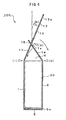
- the container 100 shown in FIG. 1 is applicable to a package box for a plurality of small sized articles, to be handled, such as PET bottles, cans, cigarettes, pencils, and filled parts and for various kinds of electric equipment or the like and one of container-constituting surfaces forms an opening 6 with a predetermined size. In other words, one of the six surfaces constituting the container 100 is opened.
- the following will describe the container-constituting surface as a container-constituting part.
- a size of the entire container 100 is constituted of a height H1, a length L1 and a width W1 and a size of the opening 6 is obtained by multiplying L1 by W1.
- a first lid-constituting part 11 constituting a first folding surface is unfolded onto the container-constituting part 1 as a side wall.
- the lid-constituting part 11 extends continuously from a side prescribing the length L1 of the container-constituting part 1 up to a length similar to the width W1 of the opening 6.
- the lid-constituting part 11 has a length extending beyond the opening 6 of L1 multiplied by W1 and has at a predetermined position a slit portion 11a with a width w1 for allowing the folding surface to be inserted.
- the lid-constituting part 11 folds and makes a mountain fold on the container-constituting part 1 on the basis of outside of the container.
- a second lid-constituting part 12 constituting a second folding surface is unfolded onto the lid-constituting part 11.
- the lid-constituting part 12 extends continuously from a side prescribing the length L1 of the lid-constituting part 11 up to a length similar to the width W1 of the opening 6.
- the lid-constituting part 12 has a size similar to that of the lid-constituting part 11 and folds and makes a valley fold on the lid-constituting part 11.
- a first lid-closing part 13 constituting a third folding surface is unfolded onto the lid-constituting part 12.
- the lid-closing part 13 extends continuously tapered from a side prescribing the length L1 of the container-constituting part 12 up to a predetermined length.
- the lid-closing part 13 has a predetermined shape and a size and folds and makes a valley fold on the lid-constituting part 12.
- the lid-closing part 13 is shaped so as to become a trapezoid with a protrusion 13a.
- the protrusion 13a constitutes a tag.
- the intermediate lid-pushing part 14 constituting a fourth folding surface is unfolded onto a container-constituting part 2 as the other side wall.
- the intermediate lid-pushing part 14 has a length across the opening 6, for example, a length similar to a width W1 of the opening 6 and folds and makes a mountain fold on the container-constituting part 2.
- the intermediate lid-pushing part 14 is positioned at a position facing at the slit portion 11a and is set to have a width meeting the width w1 of the slit portion 11a.
- a second lid-closing part 15 constituting a fifth folding surface is unfolded onto the intermediate lid-pushing part 14.
- the lid-closing part 15 has a predetermined protruded length and folds and makes a mountain fold on the intermediate lid-pushing part 14.
- the intermediate lid-pushing part 14 and the lid-closing part 15 are inserted into the above-mentioned slit portion 11a.
- the slit portion 11a is set at a position that is deviated slightly from a folded line between the lid-constituting part 11 and the lid-constituting part 12 near a side of the container-constituting part 1 and is an almost middle thereof (L1/2) and its width w1 is almost L1/3.
- L1/2 long-constituting part
- the width w1 may be set based on the length L1.
- container-constituting parts 3, 4 are disposed between the container-constituting parts 1, 2 and the container-constituting part 3 fills so as to constitute a side wall.
- the container-constituting part 4 fills so as to constitute the other side wall.
- a container-constituting part 5 fills at a side of bottom shown in FIG. 1 .
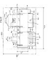
- the container material 101 of a size, for example, one shown in FIG. 2 is prepared if manufacturing the container 100 as shown in FIG. 1 .
- the container material 101 for example, coated cardboard with paper quality of 350 g/m 2 is used.
- a development may be drawn so that a coated surface thereof forms an inside of the container 100. This is because the articles contained in the container 100 are easy to slide inside the container and are easy to be loaded into an automatic machine or the like when setting parts.
- the coated cardboard has a size constituted of a vertical length W0 and a horizontal length L0. Though depending on a finished measurement of the container 100, the vertical one W0 may be almost 4W1+ H1 or more and the horizontal one L0 may be almost 2L1+2W1+a margin for connection or more.
- the container material 101 is not limited to the coated cardboard but corrugated cardboard, plastic panel with a predetermined thickness may be used therefor according to containing uses. If a container which can be used repeatedly again and again is formed, the container using the plastic panel can be increased in its used times more than that of a paper container.
- the container-constituting part 1 or 2 of length L1 and height H1 the container-constituting part 3 or 4 of width W1 and height H1
- the margin 7 for connection of height H1 are drawn below almost a half of the container material 101 and the container-constituting parts 1 and 2, the container-constituting parts 3 and 4 and the margin 7 for connection are continuously arranged so that they are aligned horizontally.
- the lid-constituting part 11 or 12 of length L1 and width W1, the trapezoidal lid-closing part 13, and the protrusion 13a having a predetermined shape are drawn on an upper part of the container-constituting part 1 so that the lid-constituting parts 11 and 12, the lid-closing part 13 and the protrusion 13a are arranged at positions that are continuous with the container-constituting part 1.
- the slit portion 11a is drawn in the lid-constituting part 11 and then is opened.
- the intermediate lid-pushing part 14 of length W1 and width w1 and the lid-closing part 15 with the predetermined length are drawn on an upper part of the container-constituting part 2 and the intermediate lid-pushing part 14 and the lid-closing part 15 are arranged at positions that are continuous with the container-constituting part 2.
- a shape of a bottom of the container 100 for example, if folding double door type, a container-constituting part 5 of length L next to the container-constituting part 2, a container-constituting piece 5a of length W1 next to the container-constituting part 3, a container-constituting part 5 of length L next to the container-constituting part 1, and a container-constituting piece 5b of length W1 next to the container-constituting part 4 are drawn.
- a container-constituting piece 8a may be disposed on a position over the container-constituting part 3 shown by alternate long and two short dashes line and a container-constituting piece 8b may be disposed on a position over the container-constituting part 4 shown thereby.
- the container-constituting piece 8a constitutes a sixth folding surface and folds and makes a mountain fold on the container-constituting part 3 next to the container-constituting part 1.
- the container-constituting piece 8b constitutes a seventh folding surface and folds and makes a mountain fold on the container-constituting part 4 next to the container-constituting part 2. Disposition of the container-constituting pieces 8a, 8b enables the strength of the entire container 100 to be increased. Of course, the disposition of the container-constituting pieces 8a, 8b may be omitted.
- broken lines show positions for mountain or valley folding.
- FIG. 1 when cutting the container material 100 along a solid line by using a cutter, scissors or the like, an exploded shape of the container 100 is completed as shown in FIG. 1 . Further, when assembling it by folding and making mountain or valley folds along the broken lines, the container 100 as shown in FIG. 9 can be completed.
- the container 100 shown in FIG. 3 is prepared.
- the container 100 is formed so that each of the container-constituting parts 1 through 4 and the margin 7 for connection in the exploded form shown in FIG. 2 folds and makes a mountain fold to form the container-constituting parts 1 through 4 as a box and the container-constituting part 4 is connected with the margin 7 for connection by an adhesive, a staple or the like.
- the container-constituting pieces 5a, 5b are then folded inwardly in advance to build up a bottom surface and the container-constituting parts 5 fold and make mountain folds onto the container-constituting pieces 5a, 5b.
- the container 100 is obtained such that the lid-constituting parts 11, 12, the lid-closing part 13 and the protrusion 13a extend upwards in succession from the container-constituting part 1; the intermediate lid-pushing part 14 and the lid-closing part 15 extend upwards in succession from the container-constituting part 2; and the opening 6 is defined.
- articles 30 are loaded into the container 100 through the opening 6 shown in FIG. 3 .
- the articles 30 are , for example, a plurality of small sized ones, to be handled, such as PET bottles, cans, cigarettes, pencils, and filled parts, various kinds of electric equipment or the like.
- the opening 6 is closed.
- the lid-constituting part 11 and the intermediate lid-pushing part 14 fold and make mountain folds on the folding positions (i), (iv) and the lid-closing part 15 and the intermediate lid-pushing part 14 are successively inserted into the slit portion 11a for allowing the folding surface to be inserted.
- the intermediate lid-pushing part 14 pushes an upper portion of the lid-constituting part 11 down and the lid-constituting part 12 folds and makes a valley fold on the folding position (ii) so that the lid-constituting part 12 covers the upper portion of the intermediate lid-pushing part 14.
- the lid-closing part 15 then folds and makes a mountain fold on the folding position (v) so that the lid-closing part 15 wraps the container-constituting part 1.
- the lid-closing part 13 folds and makes a mountain fold on the folding position (iii) and the lid-closing part 13 is engaged with the container-constituting part 1 with the lid-closing part 13 wrapping the lid-closing part 15.
- a double-sided tape sticks the protrusion 13a and the container-constituting part 1.
- a sticking method is not limited thereto.
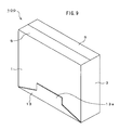
- the opening 6 in the container 100 can be firmly closed (see FIG. 9 ).
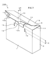
- the container-constituting part 1 shown in FIG. 7 has a pair of slit portions 1a, 1b for allowing folding parts to be engaged at predetermined positions. A length of each of the slits 1a, 1b is 12.
- the slits 1a, 1b are provided at positions of the container-constituting part 1 which lid-closing pieces 13b, 13c face when the lid-closing part 13 closes over the container-constituting part 1.
- the lid-closing pieces 13b, 13c constituting first and second folding pieces with a predetermined width w2 are provided at both sides of the protrusion 13a extending from the lid-closing part 13.
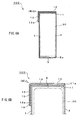
- the lid-closing part 13 on the occasion of its engagement with reference to FIGS. 8A and 8B .
- the lid-closing piece 13b is inserted into the slit portion 1a shown in FIG. 7 and the lid-closing piece 13c is inserted into the slit portion 1b, respectively.
- the lid-closing piece 13b shown in FIG. 8A is inserted into the slit 1a and it is configured that by catching the lid-closing piece 13b in the slit 1a, the lid-closing part 13 shown in FIG. 8B is engaged with the container-constituting part 1.
- the lid-closing piece 13c also acts similarly.
- the lid-closing part 13 can be firmly fixed onto the container-constituting part 1. Even if the container-constituting parts 5 direct upward and a double-lid-structure part directs downward, it is capable to keep the opening shown in FIG. 7 firmly closed.
- Such a configuration of the container 100 enables the articles that are subject to scattering to be easily handled by the container-constituting parts 1 through 5 and the lid-constituting parts 11, 12. That enables the contents therein to be protected when carrying them or transporting them.
- the container 100 is set to the automatic machine 400 or the like with a side of its lid-closing part directing downward.
- the automatic machine 400 shown in FIG. 10 is a vending machine, a binding machine, various kinds of power tools or the like and has a loading space 401 for loading the container 100 as shown in FIG. 7 .
- the loading space 401 is blocked in its three directions. Namely, there is a situation such that an operator's hand cannot enter into right and left side surfaces and a back surface of the loading space 401.
- a side of a bottom surface of the loading space 401 becomes parts-loading space 402, which has often such a structure that an operator's hand cannot enter into it depending on a type of automatic machine 400.
- the container 100 with double-lid structure according to the present invention is loaded into the automatic machine 400 having such a loading space 401, the container 100 is laded (set) so that it directs from an upper part of the loading space 401 to a lower part thereof or from a front surface thereof to a back surface thereof.
- a mechanism of stopping the container 100 at a middle of the loading space 401 is provided.
- a stopper mechanism is provided at the right or left side surface or a back surface of the loading space 401 and it is configured that when dropping the container 100 from the upper part of the loading space 401 to a lower part thereof along the space, the stopper mechanism stops movement of the container 100.
- Such a mechanism enables to be realized a structure in which the operator's hand can enter into a lower part of the loading space 401 under the container 100 stopping at a middle thereof, thereby keeping any working space.
- it is configured that the lid-constituting parts 11 and 12 are opened by pulling the lid-closing part 13 positioned at this side under a situation where the container 100 is set into the above-mentioned loading space 401.
- FIGS. 12A and 12B through 14 a lid-opening example of the container 100 with reference to FIGS. 12A and 12B through 14 .
- a case is illustrated where the container 100 in which the lid-closing pieces 13b, 13c shown in FIG. 7 have been engaged with the slits 1a, 1b is opened.
- the opening 6, not shown is opened by pulling the lid-closing part 13 out of the container-constituting part 1 as shown in FIG. 12A
- the lid-closing pieces 13b, 13c are disengaged with the slits 1a, 1b and the protrusion 13a is also disengaged with the container-constituting part 1.
- the lid-closing part 13 is pulled toward this side.
- FIG. 12B where this portion is enlarged, the lid-closing piece 13b is pulled out of the slit portion 1a and the lid-closing piece 13c is pulled out of the slit portion 1b as well as the lid-closing piece 13b is separated from the slit portion 1a and the lid-closing piece 13c is separated from the slit portion 1b.
- the intermediate lid-pushing part 14 under the lid-constituting part 11 becomes a state just before it becomes free.
- the intermediate lid-pushing part 14 and the lid-closing part 15 are successively pulled out of the slit portion 11a for allowing the folding surface to be inserted, as shown in FIG. 13A .
- a user is pulling the lid-closing part 13 toward this side.
- FIG. 13B where this portion is enlarged, the lid-closing part 15 and the intermediate lid-pushing part 14 are pulled out of the slit portion 11a in this order.
- the lid-constituting parts 11, 12 and the lid-closing part 13 are disengaged from the intermediate lid-pushing part 14 and the lid-closing part 15 so that the lid-constituting parts 11, 12 covering the opening 6 can be opened.
- the intermediate lid-pushing part 14 and the lid-closing part 15 go back by being pushed by the articles 30. This enables the opening 6 to be formed, thereby allowing the articles 30 loaded in the container 100 to be fallen freely and allowing the articles 30 to be loaded into the automatic machine 400 shown in FIG. 10 .
- the lid-constituting parts 11, 12 and the lid-closing part 13 are combined with the intermediate lid-pushing part 14 and the lid-closing part 15 so that the lid-constituting parts 11, 12 can cover the opening 6 and the opening 6 can be closed doubly by the lid-constituting parts 11, 12 and the intermediate lid-pushing part 14. Further, it is possible to open the opening 6 only by pulling the lid-constituting parts 11, 12 at a side of the container-constituting part 1.
- slits 1d, 1e for assisting opening and closure are provided in a container-constituting part 1 on a vertical direction thereof.
- the slits 1d, 1e are provided in the container 200 at a side of disposition of double-lid structure and are provided at right and left two positions on a surface lying on the same plane of the container-constituting part 1.
- Length of each of the slits 1d, 1e is 13.
- the length 13 is almost a half of a height H1 of the container 200. This is figured out to enable the lid-constituting part 11 to be further pulled toward this side. It is possible to open the opening 6 wider than that of the first embodiment, which is easy to set the articles 30 in the container to the automatic machine 400 or the like.
- a handle 5e and an opening 5f for the handle are provided on an upper part of the container 200 so that the container 200 is easy to be carried.
- the handle 5e and the opening 5f are disposed on the container-constituting part 2 at an opposite position to the disposed position of the intermediate lid-pushing part 14.
- a container-constituting part 5c is provided on the container 200 at an opposite position to the disposed position of the double-lid structure thereof.
- a circular window portion 5d is provided so that the articles 30, not shown, in the container can be checked through visual inspection. This is because an occasion in which the articles 30 in the container are checked from outside by their color or the like may arise.
- the slits 1d, 1e may be provided at a side of the container-constituting part 2.
- the slits 1d, 1e are provided at positions of the container-constituting part 2, which are identical to those of the container-constituting part 1.
- the disposition of the double-lid structure directs downwards and the lid-closing part 13 is removed to open the opening 6.
- the lid-closing part 13 is removed from the container-constituting part 1 as shown in FIG. 16 and the lid-closing part 13 is pulled toward this side.
- the container-constituting part 1 is curved due to the slits 1d, 1e provided on a vertical direction by a larger amount than that of the first embodiment so that it is possible to open the opening 6 much wider.
- the container material 201 As shown in FIG. 17 , if the container 200 as shown in FIG. 15 is manufactured, the container material 201 having, for example, a size shown in FIG. 17 is prepared.
- the container material 201 coated cardboard with paper quality of 350 g/m 2 is used, similar to the first embodiment. In this embodiment, a development may be also drawn so that a coated surface thereof forms an inside of the container 200. The reason therefor has been described in the first embodiment, the description of which will be omitted.
- the coated cardboard has a size constituted of a vertical length W0' and a horizontal length L0.
- the container material 201 that is larger than that of the first embodiment is prepared to form the handle 5e and the container-constituting part 5c. Though depending on a finished measurement of the container 200, the vertical length W0' may be almost 5W1+ H1 or more and the horizontal one L0 may be almost 2L1+2W1+a margin for connection or more.
- the container material 201 is not limited to the coated cardboard but the ones described in the first embodiment may be used therefor.
- the slits 1d, 1e are drawn so that they are provided in the container-constituting part 1 and slits 1f, 1g are drawn so that they are provided in the container-constituting part 2.
- the handle 5e and the opening 5f are drawn so that they extend continuously from the container-constituting part 2 at an opposite side of the disposed position of the double-lid structure.
- the handle 5e and the opening 5f are reinforced through the double structure to obtain any strength.
- the handle 5e' and the opening 5f' are reversed patterns of the handle 5e and the opening 5f.
- the handle 5e' is set so that its projection length is larger than that of the handle 5e.
- both sides of each of the handles 5e, 5e' make mountain folds and bends inwardly to each other to maintain the strength thereof and both of the triangular mountain-folded portions are folded inwardly. This enables both sides of each of the handles 5e, 5e' to be formed slantwise as shown in FIG. 15 .
- the container-constituting part 5c is drawn at a position of the container 200 so that it extends continuously from the container-constituting part 1 at an opposite side of the disposed position of the double-lid structure.
- a circular window portion 5d is disposed in the container-constituting part 5c.
- Other parts thereof are similar to those of FIG. 2 , the description of which will be omitted.
- the slits 1d, 1e or the like are provided at both of the right and left sides of the container-constituting part 1 on a vertical direction so that it is possible to curve the container-constituting part 1 by a large amount when opening the lid. Accordingly, the opening 6 can be opened by larger amount, thereby enabling operability at a front surface to be improved as compared by that of the first embodiment.
- a container 300 As a third embodiment with reference to FIG. 18 .
- a case is illustrated where the opening 6' is broader than that of the first embodiment.
- a height of the container is H3, a length thereof is L3 and a width thereof is W3.
- a size of the opening 6' is obtained by multiplying L3 by W3.
- the embodiment is a case where, of the container, the height is less than that of the first embodiment, H3 ⁇ H1 and the size of the opening 6' is broader, L3 by W3>L1 by W1.
- the double-lid structure directing downwards has been described in the first embodiment, it may be used with the double-lid structure directing upwards as shown in the third embodiment.
- This enables the double-lid structure at upper surface thereof to be opened by one operation. It is possible to expose the opening 6' with a single touch.
- the lid-constituting part 31 extends continuously from a side prescribing the length L3 of a container-constituting part 1' up to a length that is almost identical to the width W3 of he opening 6'.
- the lid-constituting part 31 has a length across the opening 6' of L3 by W3, and has at a predetermined position a slit portion 31a for allowing the folding surface to be inserted with a width w3.
- the lid-constituting part 31 folds and makes a mountain fold on the container-constituting part 1' on the basis of outside of the container.
- a lid-constituting part 32 is unfolded onto the lid-constituting part 31.
- the lid-constituting part 32 extends continuously from a side prescribing the length L3 of the lid-constituting part 31 up to a length that is almost identical to the width W3 of he opening 6'.
- the lid-constituting part 32 has a size similar to that of the lid-constituting part 31 and folds and makes a valley fold on the lid-constituting part 31.
- a lid-closing part 33 is unfolded onto the lid-constituting part 32.
- the lid-closing part 33 extends continuously from a side prescribing the length L3 of the container-constituting part 32 up to a predetermined length.
- the lid-closing part 33 has predetermined shape and size and folds and makes a valley fold on the lid-constituting part 32.
- the lid-closing part 33 is shaped so as to become a trapezoid with a protrusion 33a.
- the protrusion 33a constitutes a tag.
- the intermediate lid-pushing part 34 is unfolded onto a container-constituting part 2', not shown, as the other side wall.
- the intermediate lid-pushing part 34 has a length across the opening 6', for example, a length that is almost identical to a width W3 of the opening 6' and folds and makes a mountain fold on the container-constituting part 2'.
- the intermediate lid-pushing part 34 is positioned at a position facing at the slit portion 31a and is set to have a width meeting the width w3 of the slit portion 31a.
- a lid-closing part 35 is unfolded onto the intermediate lid-pushing part 34.
- the lid-closing part 35 has a predetermined protruded length and folds and makes a mountain fold on the intermediate lid-pushing part 34.
- the intermediate lid-pushing part 34 and the lid-closing part 35 are inserted into the above-mentioned slit portion 31a.
- the slit portion 31a is set at a position that is deviated slightly from a folded line between the lid-constituting part 31 and the lid-constituting part 32 near a side of the container-constituting part 1' and is a middle thereof (L3/2) and its width w3 is almost L3/3.
- L3/2 middle thereof
- the width w3 may be set based on the length L3.
- the lid-constituting parts 31, 32 and the lid-closing part 33 are combined with the intermediate lid-pushing part 34 and the lid-closing part 35 so that the lid-constituting parts 31, 32 can cover the opening 6' and the opening 6' can be closed doubly by the lid-constituting parts 31, 32 and the intermediate lid-pushing part 34. Further, it is possible to open the opening 6' only by pulling the lid-constituting parts 31, 32 at a side of the container-constituting part 1'.
- the present invention is very preferably applicable to a carton containing a plurality of small sized articles, to be handled, such as PET bottles, cans, cigarettes, pencils, and filled parts and a package box for various kinds of electric equipment, an appliance or the like.
Landscapes
- Engineering & Computer Science (AREA)
- Mechanical Engineering (AREA)
- Cartons (AREA)
- Packages (AREA)
Abstract
A container is provided with, as shown in FIG. 1 , an opening 6, a lid-constituting part 11 that makes a mountain fold on a container-constituting part 1 and has a slit portion 11a, a lid-constituting part 12 that makes a valley fold on the lid-constituting part 11 and has the same size as that thereof, a lid-closing part 13 that makes a valley fold on the lid-constituting part 12 and has a predetermined shape and a size, an intermediate lid-pushing part 14 that makes a mountain fold on a container-constituting part 2 and has a length extending beyond the opening 6, and a lid-closing part 15 that makes a mountain fold on the intermediate lid-pushing part 14 and has a predetermined extended length. The lid-closing part 15 and the intermediate lid-pushing part 14 are successively inserted into the slit portion 11a, the intermediate lid-pushing part 14 covers the lid-constituting part 11 and the lid-constituting part 12 covers the intermediate lid-pushing part 14. By taking such a configuration, it is possible to close the opening doubly as well as it is possible to open the opening easily.
Description
- The present invention relates to a container, which is preferably applied to a carton containing a plurality of small sized articles, to be handled, such as PET bottles, cans, cigarettes, pencils, and filled parts and a package box for various kinds of electric equipment or the like. More particularly, it relates to a container, one of container-constituting surfaces of which has an opening with a predetermined size, which is provided with five container-constituting portions that make mountain or valley fold, the container-constituting portions having predetermined shapes and sizes. The container is constituted so that a lid-closing part and an intermediate lid-pushing part are successively inserted into a slit of a first lid-constituting part, the intermediate lid-pushing part covers the first lid-constituting part and a second lid-constituting part covers the intermediate lid-pushing part so that the lid-closing part wraps a container-constituting part, and the other lid-closing part is engaged with the container-constituting portion with the other lid-closing part wrapping the lid-closing part. By configuring the container so as to be so, it is possible to close the opening doubly by the first and second lid-constituting parts and the intermediate lid-pushing part as well as it is possible to open the opening only by pulling the lid-constituting parts and the lid-closing parts from a side of the container-constituting portion to a side of the container-constituting surface.
- Conventionally, a plurality of small sized articles, to be handled, such as PET bottles, cans, cigarettes, pencils, and filled parts has been often distributed with a desired carton containing them or various kinds of electric equipment or the like have been often distributed with a package box using corrugated cardboard containing them. Such a carton or a package box is made by performing the taking of measurements on carton material or box material with a predetermined size, creating a development of the container, cutting notches into predetermined portions of the developed container and erecting the container by making mountain or valley fold on the carton material or box material.
- In accordance with such a container, a packing case for supplement of article and a method of supplementing the article for a vending machine using the same have been disclosed in Japanese Patent Application Publication No.
Hei05-04640 - Further, a package box has been disclosed in Japanese Patent Application Publication No.
2001-02057 - Further, a package with a dispenser has been disclosed in Japanese Patent Application Publication No.
2005-53555 - An opening assist for a dispensing carton has been disclosed in Japanese Patent Application Publication No.
2005-53584 - According to the conventional containers each having the opening, however, as disclosed in Japanese Patent Application Publication No.
Hei05-04640 2001-02057 2005-53555 2005-53584 Hei05-04640 2001-02057 2005-53555 2005-53584 - Particularly, if a plurality of small articles each having a complicated shape is installed into the automatic machine or the like when the container with the dispenser disclosed in any of Japanese Patent Application Publication No.
Hei05-04640 2001-02057 2005-53555 2005-53584 - A container according to the present invention in which one of container-constituting surfaces forms an opening with a predetermined size, is characterized in that if two constituting surfaces standing facing each other across the opening are supposed as first and second constituting surfaces, it is provided with a first folding surface that makes a mountain fold on the first constituting surface, the first folding surface having a length extending beyond the opening, a second folding surface that makes a valley fold on the first folding surface, a third folding surface that makes a valley fold on the second folding surface, a fourth folding surface that makes a mountain fold on the second constituting surface, the fourth folding surface having a predetermined length, and at a predetermined position, a slit portion for allowing the fourth folding surface to be inserted, wherein when the opening is closed, the fourth folding surface is inserted into the slit portion for allowing the folding surface to be inserted, the fourth folding surface covers the first folding surface and the second folding surface covers the fourth folding surface so that the third folding surface is engaged with the first constituting surface.
- In the container according to the present invention, when the opening formed by one of the container-constituting surfaces is closed, the first, second and third folding surfaces and the fourth folding surface are assembled so that the first and second folding surfaces can cover the opening and the first, second and fourth folding surfaces can close the opening doubly. Further, it is possible to open the opening easily and simply only by pulling the first folding surface and the second folding surface from a side of the first constituting surface toward a side of the first constituting surface. Accordingly, the articles contained in the container can be discharged downwardly with a good reproducibility in a state where its opening side stands facing downwards under pull-out operation to the side of the first constituting surface. This enables it to be amply applied to a charge and storage of the articles to the vending machine or various kinds of part cassettes.
-
- [
FIG. 1 ] is a conceptual diagram showing a configuration example of acontainer 100 as an embodiment according to the present invention. - [
FIG. 2 ] is a diagram showing an example of measurements incontainer material 101. - [
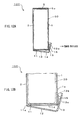
FIG. 3 ] is an assembly process diagram showing a lid closure example (part one thereof) of thecontainer 100 according to a first embodiment. - [
FIG. 4 ] is the assembly process diagram showing the lid closure example (part two thereof) of thecontainer 100. - [
FIG. 5A ] is the assembly process diagram showing the lid closure example (part three thereof) of thecontainer 100. - [
FIG. 5B ] is an enlarged diagram showing the lid closure example in thecontainer 100. - [
FIG. 6A ] is the assembly process diagram showing the lid closure example (part four thereof) of thecontainer 100. - [
FIG. 6B ] is an enlarged diagram showing the lid closure example in thecontainer 100. - [
FIG. 7 ] is a perspective view showing another engaging example of a lid-closingpart 13. - [
FIG. 8A ] is a cross sectional view showing a configuration example of the lid-closingpart 13 on the occasion of its engagement. - [
FIG. 8B ] is an enlarged view showing a configuration example of the lid-closingpart 13 on the occasion of its engagement. - [
FIG. 9 ] is a perspective view showing an aspect example of thecontainer 100 on the occasion of a completion of the lid closure. - [
FIG. 10 ] is a perspective view showing a configuration example when thecontainer 100 is loaded to anautomatic machine 400 or the like. - [
FIG. 11 ] is a perspective view showing a loaded example of thecontainer 100. - [
FIG. 12A ] is a cross sectional view showing a lid-opening example (part one thereof) of thecontainer 100. - [
FIG. 12B ] is an enlarged view showing the lid-opening example of thecontainer 100. - [
FIG. 13A ] is a cross sectional view showing the lid-opening example (part two thereof) of thecontainer 100. - [
FIG. 13B ] is an enlarged view showing the lid-opening example of thecontainer 100. - [
FIG. 14 ] is a cross sectional view showing the lid-opening example (part three thereof) of thecontainer 100. - [
FIG. 15 ] is a perspective view showing a configuration example of acontainer 200 as a second embodiment. - [
FIG. 16 ] is a perspective view showing an opening example of theopening 6 in thecontainer 200. - [
FIG. 17 ] is a diagram showing an example of measurements incontainer material 201. - [
FIG. 18 ] is a perspective view showing an aspect example of acontainer 300 as a third embodiment. - The present invention has an object to provide a container by which when one of container-constituting surfaces forms an opening with a predetermined size, the opening may be closed doubly by devising a closure mechanism and may be opened easily only by pulling a part of the closure mechanism.
- The following will describe embodiments of a container according to the present invention with reference to drawings. The
container 100 shown inFIG. 1 is applicable to a package box for a plurality of small sized articles, to be handled, such as PET bottles, cans, cigarettes, pencils, and filled parts and for various kinds of electric equipment or the like and one of container-constituting surfaces forms anopening 6 with a predetermined size. In other words, one of the six surfaces constituting thecontainer 100 is opened. The following will describe the container-constituting surface as a container-constituting part. - A size of the
entire container 100 is constituted of a height H1, a length L1 and a width W1 and a size of theopening 6 is obtained by multiplying L1 by W1. In thecontainer 100, if two container-constituting parts standing facing each other across theopening 6 are supposed as first and second container-constitutingparts part 11 constituting a first folding surface is unfolded onto the container-constitutingpart 1 as a side wall. In this embodiment, the lid-constitutingpart 11 extends continuously from a side prescribing the length L1 of the container-constitutingpart 1 up to a length similar to the width W1 of theopening 6. The lid-constitutingpart 11 has a length extending beyond theopening 6 of L1 multiplied by W1 and has at a predetermined position a slit portion 11a with a width w1 for allowing the folding surface to be inserted. The lid-constitutingpart 11 folds and makes a mountain fold on the container-constitutingpart 1 on the basis of outside of the container. - A second lid-constituting
part 12 constituting a second folding surface is unfolded onto the lid-constitutingpart 11. In this embodiment, the lid-constitutingpart 12 extends continuously from a side prescribing the length L1 of the lid-constitutingpart 11 up to a length similar to the width W1 of theopening 6. The lid-constitutingpart 12 has a size similar to that of the lid-constitutingpart 11 and folds and makes a valley fold on the lid-constitutingpart 11. A first lid-closingpart 13 constituting a third folding surface is unfolded onto the lid-constitutingpart 12. In this embodiment, the lid-closingpart 13 extends continuously tapered from a side prescribing the length L1 of the container-constitutingpart 12 up to a predetermined length. The lid-closingpart 13 has a predetermined shape and a size and folds and makes a valley fold on the lid-constitutingpart 12. In this embodiment, the lid-closingpart 13 is shaped so as to become a trapezoid with aprotrusion 13a. Theprotrusion 13a constitutes a tag. - The intermediate lid-pushing
part 14 constituting a fourth folding surface is unfolded onto a container-constitutingpart 2 as the other side wall. In this embodiment, the intermediate lid-pushingpart 14 has a length across theopening 6, for example, a length similar to a width W1 of theopening 6 and folds and makes a mountain fold on the container-constitutingpart 2. The intermediate lid-pushingpart 14 is positioned at a position facing at the slit portion 11a and is set to have a width meeting the width w1 of the slit portion 11a. A second lid-closingpart 15 constituting a fifth folding surface is unfolded onto the intermediate lid-pushingpart 14. The lid-closingpart 15 has a predetermined protruded length and folds and makes a mountain fold on the intermediate lid-pushingpart 14. - The intermediate lid-pushing
part 14 and the lid-closingpart 15 are inserted into the above-mentioned slit portion 11a. The slit portion 11a is set at a position that is deviated slightly from a folded line between the lid-constitutingpart 11 and the lid-constitutingpart 12 near a side of the container-constitutingpart 1 and is an almost middle thereof (L1/2) and its width w1 is almost L1/3. Of course, it is not limited thereto but it may be almost L1/4. The width w1 may be set based on the length L1. This is because the strength of the lid-constitutingpart 11, the lid-constitutingpart 12 and the like is kept by balancing the strength of theopening 6 and any portion other than theopening 6 when the intermediate lid-pushingpart 14 and the lid-closingpart 15 are inserted into the slit portion 11a. Regarding other container-constituting parts, container-constitutingparts parts part 3 fills so as to constitute a side wall. The container-constitutingpart 4 fills so as to constitute the other side wall. A container-constitutingpart 5 fills at a side of bottom shown inFIG. 1 . Thus, thecontainer 100 with a double lid structure is configured. - The following will describe a method of manufacturing the
container 100 with reference toFIG. 2 . According to a measurement example of a container material 101 (exploded example of the container 100) shown inFIG 2 , thecontainer material 101 of a size, for example, one shown inFIG. 2 is prepared if manufacturing thecontainer 100 as shown inFIG. 1 . As thecontainer material 101, for example, coated cardboard with paper quality of 350 g/m2 is used. A development may be drawn so that a coated surface thereof forms an inside of thecontainer 100. This is because the articles contained in thecontainer 100 are easy to slide inside the container and are easy to be loaded into an automatic machine or the like when setting parts. - The coated cardboard has a size constituted of a vertical length W0 and a horizontal length L0. Though depending on a finished measurement of the
container 100, the vertical one W0 may be almost 4W1+ H1 or more and the horizontal one L0 may be almost 2L1+2W1+a margin for connection or more. Thecontainer material 101 is not limited to the coated cardboard but corrugated cardboard, plastic panel with a predetermined thickness may be used therefor according to containing uses. If a container which can be used repeatedly again and again is formed, the container using the plastic panel can be increased in its used times more than that of a paper container. - According to the expanded example of the
container 101 shown inFIG. 2 , the container-constitutingpart part margin 7 for connection of height H1 are drawn below almost a half of thecontainer material 101 and the container-constitutingparts parts margin 7 for connection are continuously arranged so that they are aligned horizontally. Further, the lid-constitutingpart part 13, and theprotrusion 13a having a predetermined shape are drawn on an upper part of the container-constitutingpart 1 so that the lid-constitutingparts part 13 and theprotrusion 13a are arranged at positions that are continuous with the container-constitutingpart 1. The slit portion 11a is drawn in the lid-constitutingpart 11 and then is opened. - Further, the intermediate lid-pushing
part 14 of length W1 and width w1 and the lid-closingpart 15 with the predetermined length are drawn on an upper part of the container-constitutingpart 2 and the intermediate lid-pushingpart 14 and the lid-closingpart 15 are arranged at positions that are continuous with the container-constitutingpart 2. Further, regarding a shape of a bottom of thecontainer 100, for example, if folding double door type, a container-constitutingpart 5 of length L next to the container-constitutingpart 2, a container-constituting piece 5a of length W1 next to the container-constitutingpart 3, a container-constitutingpart 5 of length L next to the container-constitutingpart 1, and a container-constitutingpiece 5b of length W1 next to the container-constitutingpart 4 are drawn. - It is to be noted that, in the figure, a container-constituting piece 8a may be disposed on a position over the container-constituting
part 3 shown by alternate long and two short dashes line and a container-constituting piece 8b may be disposed on a position over the container-constitutingpart 4 shown thereby. The container-constituting piece 8a constitutes a sixth folding surface and folds and makes a mountain fold on the container-constitutingpart 3 next to the container-constitutingpart 1. The container-constituting piece 8b constitutes a seventh folding surface and folds and makes a mountain fold on the container-constitutingpart 4 next to the container-constitutingpart 2. Disposition of the container-constituting pieces 8a, 8b enables the strength of theentire container 100 to be increased. Of course, the disposition of the container-constituting pieces 8a, 8b may be omitted. - In the figure, broken lines show positions for mountain or valley folding. In this example, when cutting the
container material 100 along a solid line by using a cutter, scissors or the like, an exploded shape of thecontainer 100 is completed as shown inFIG. 1 . Further, when assembling it by folding and making mountain or valley folds along the broken lines, thecontainer 100 as shown inFIG. 9 can be completed. - The following will describe a lid closure example (part one through three thereof) of the
container 100 according to a first embodiment with reference toFIGS. 3 through 6A and 6B . Triangle marks (i) through (v) in white shown inFIGS. 3 through 5A and 5B are all folding positions. - First, the
container 100 shown inFIG. 3 is prepared. Thecontainer 100 is formed so that each of the container-constitutingparts 1 through 4 and themargin 7 for connection in the exploded form shown inFIG. 2 folds and makes a mountain fold to form the container-constitutingparts 1 through 4 as a box and the container-constitutingpart 4 is connected with themargin 7 for connection by an adhesive, a staple or the like. The container-constitutingpieces 5a, 5b are then folded inwardly in advance to build up a bottom surface and the container-constitutingparts 5 fold and make mountain folds onto the container-constitutingpieces 5a, 5b. It is constituted that butt portions of the container-constitutingparts 5 are stuck onto each other by a tape or the like. Thus, as shown inFIG. 3 , thecontainer 100 is obtained such that the lid-constitutingparts part 13 and theprotrusion 13a extend upwards in succession from the container-constitutingpart 1; the intermediate lid-pushingpart 14 and the lid-closingpart 15 extend upwards in succession from the container-constitutingpart 2; and theopening 6 is defined. - In this embodiment,
articles 30 are loaded into thecontainer 100 through theopening 6 shown inFIG. 3 . thearticles 30 are , for example, a plurality of small sized ones, to be handled, such as PET bottles, cans, cigarettes, pencils, and filled parts, various kinds of electric equipment or the like. Next, as shown inFIG. 4 , theopening 6 is closed. In this moment, the lid-constitutingpart 11 and the intermediate lid-pushingpart 14 fold and make mountain folds on the folding positions (i), (iv) and the lid-closingpart 15 and the intermediate lid-pushingpart 14 are successively inserted into the slit portion 11a for allowing the folding surface to be inserted. - Further, as shown in
FIGS. 5A and 5B , the intermediate lid-pushingpart 14 pushes an upper portion of the lid-constitutingpart 11 down and the lid-constitutingpart 12 folds and makes a valley fold on the folding position (ii) so that the lid-constitutingpart 12 covers the upper portion of the intermediate lid-pushingpart 14. The lid-closingpart 15 then folds and makes a mountain fold on the folding position (v) so that the lid-closingpart 15 wraps the container-constitutingpart 1. At the same time, as shown inFIGS. 6A and 6B , the lid-closingpart 13 folds and makes a mountain fold on the folding position (iii) and the lid-closingpart 13 is engaged with the container-constitutingpart 1 with the lid-closingpart 13 wrapping the lid-closingpart 15. In this embodiment, a double-sided tape sticks theprotrusion 13a and the container-constitutingpart 1. Of course, a sticking method is not limited thereto. Thus, theopening 6 in thecontainer 100 can be firmly closed (seeFIG. 9 ). - The following will describe another engaging method of the lid-closing
part 13 in thecontainer 100 with reference toFIG. 7 . The container-constitutingpart 1 shown inFIG. 7 has a pair of slit portions 1a, 1b for allowing folding parts to be engaged at predetermined positions. A length of each of the slits 1a, 1b is 12. The slits 1a, 1b are provided at positions of the container-constitutingpart 1 which lid-closing pieces 13b, 13c face when the lid-closingpart 13 closes over the container-constitutingpart 1. The lid-closing pieces 13b, 13c constituting first and second folding pieces with a predetermined width w2 are provided at both sides of theprotrusion 13a extending from the lid-closingpart 13. The width w2 of each of the lid-closing pieces 13b, 13c is set so as to be almost 12 (w2=12). Both of the lid-closing pieces 13b, 13c fold and make mountain folds on theprotrusion 13a. Forward end of each of the lid-closing pieces 13b, 13c has a shape of circular arc. This is because they cause the articles loaded in thecontainer 100 to be protected. - Here, the following will describe a configuration example of the lid-closing
part 13 on the occasion of its engagement with reference toFIGS. 8A and 8B . In this embodiment, it is configured that when the lid-closingpart 13 is engaged with the container-constitutingpart 1, the lid-closing piece 13b is inserted into the slit portion 1a shown inFIG. 7 and the lid-closing piece 13c is inserted into the slit portion 1b, respectively. In other words, the lid-closing piece 13b shown inFIG. 8A is inserted into the slit 1a and it is configured that by catching the lid-closing piece 13b in the slit 1a, the lid-closingpart 13 shown inFIG. 8B is engaged with the container-constitutingpart 1. The lid-closing piece 13c also acts similarly. - Then, the following will describe an aspect example of the
container 100 on the occasion of a completion of the lid closure with reference toFIG. 9 . According to thecontainer 100 shown inFIG. 9 , the lid-closingpart 13 can be firmly fixed onto the container-constitutingpart 1. Even if the container-constitutingparts 5 direct upward and a double-lid-structure part directs downward, it is capable to keep the opening shown inFIG. 7 firmly closed. Such a configuration of thecontainer 100 enables the articles that are subject to scattering to be easily handled by the container-constitutingparts 1 through 5 and the lid-constitutingparts container 100 into any automatic machine, a power tool or the like, it is possible to open the lid-constitutingparts container 100 is set on the machine, tool or the like. - The following will describe a loaded example of the
container 100 with reference toFIGS. 10 and11 . In this embodiment, thecontainer 100 is set to theautomatic machine 400 or the like with a side of its lid-closing part directing downward. Theautomatic machine 400 shown inFIG. 10 is a vending machine, a binding machine, various kinds of power tools or the like and has aloading space 401 for loading thecontainer 100 as shown inFIG. 7 . Theloading space 401 is blocked in its three directions. Namely, there is a situation such that an operator's hand cannot enter into right and left side surfaces and a back surface of theloading space 401. A side of a bottom surface of theloading space 401 becomes parts-loading space 402, which has often such a structure that an operator's hand cannot enter into it depending on a type ofautomatic machine 400. When thecontainer 100 with double-lid structure according to the present invention is loaded into theautomatic machine 400 having such aloading space 401, thecontainer 100 is laded (set) so that it directs from an upper part of theloading space 401 to a lower part thereof or from a front surface thereof to a back surface thereof. - According to the loaded example of the
container 100 shown inFIG. 11 , a mechanism of stopping thecontainer 100 at a middle of theloading space 401 is provided. For example, a stopper mechanism, not shown, is provided at the right or left side surface or a back surface of theloading space 401 and it is configured that when dropping thecontainer 100 from the upper part of theloading space 401 to a lower part thereof along the space, the stopper mechanism stops movement of thecontainer 100. Such a mechanism enables to be realized a structure in which the operator's hand can enter into a lower part of theloading space 401 under thecontainer 100 stopping at a middle thereof, thereby keeping any working space. In this embodiment, it is configured that the lid-constitutingparts part 13 positioned at this side under a situation where thecontainer 100 is set into the above-mentionedloading space 401. - The following will describe a lid-opening example of the
container 100 with reference toFIGS. 12A and 12B through 14 . In this embodiment, a case is illustrated where thecontainer 100 in which the lid-closing pieces 13b, 13c shown inFIG. 7 have been engaged with the slits 1a, 1b is opened. First, when theopening 6, not shown, is opened by pulling the lid-closingpart 13 out of the container-constitutingpart 1 as shown inFIG. 12A , the lid-closing pieces 13b, 13c are disengaged with the slits 1a, 1b and theprotrusion 13a is also disengaged with the container-constitutingpart 1. In this moment, it is configured that the lid-closingpart 13 is pulled toward this side. According toFIG. 12B where this portion is enlarged, the lid-closing piece 13b is pulled out of the slit portion 1a and the lid-closing piece 13c is pulled out of the slit portion 1b as well as the lid-closing piece 13b is separated from the slit portion 1a and the lid-closing piece 13c is separated from the slit portion 1b. By such a separation operation, the intermediate lid-pushingpart 14 under the lid-constitutingpart 11 becomes a state just before it becomes free. - Next, it is configured that the intermediate lid-pushing
part 14 and the lid-closingpart 15 are successively pulled out of the slit portion 11a for allowing the folding surface to be inserted, as shown inFIG. 13A . In this moment, it is configured that a user is pulling the lid-closingpart 13 toward this side. According toFIG. 13B where this portion is enlarged, the lid-closingpart 15 and the intermediate lid-pushingpart 14 are pulled out of the slit portion 11a in this order. By such a pulling operation, thearticles 30 loaded in thecontainer 100 are barely held by sections of the lid-constitutingpart 11 and the intermediate lid-pushingpart 14 so as to become a situation just before thearticles 30 drop. - According to the
container 100 shown inFIG. 14 , by keeping further pulling the lid-closingpart 13 toward this side, the lid-constitutingparts part 13 are disengaged from the intermediate lid-pushingpart 14 and the lid-closingpart 15 so that the lid-constitutingparts opening 6 can be opened. In this moment, by keeping further pulling the lid-closingpart 13 toward this side, the intermediate lid-pushingpart 14 and the lid-closingpart 15 go back by being pushed by thearticles 30. This enables theopening 6 to be formed, thereby allowing thearticles 30 loaded in thecontainer 100 to be fallen freely and allowing thearticles 30 to be loaded into theautomatic machine 400 shown inFIG. 10 . - Thus, according to the
container 100 as the first embodiment, when closing theopening 6 constituting one of the six container-constituting parts, the lid-constitutingparts part 13 are combined with the intermediate lid-pushingpart 14 and the lid-closingpart 15 so that the lid-constitutingparts opening 6 and theopening 6 can be closed doubly by the lid-constitutingparts part 14. Further, it is possible to open theopening 6 only by pulling the lid-constitutingparts part 1. Accordingly, it is possible to take thearticles 30 contained in thecontainer 100 out thereof downwardly with a good reproducibility under the situation where the side of theopening 6 directs downward by pulling operation at a side of the container-constitutingpart 1. Thus, it is capable of being sufficiently applied to a loading and containing system of thearticles 30 to various kinds of parts cassettes of a vending machine, binder device, a power tool or the like. It is also not necessary to enter the hand into a machine, a tool or the like so that safety is given and by allowing the lower-surface-double-lid-body to be opened by only one operation, it is possible to load parts or the like onto theloading space 401 under one-touch control. - The following will describe a configuration example of a
container 200 as a second embodiment with reference toFIG. 15 . According to thecontainer 200 shown inFIG. 15 , slits 1d, 1e for assisting opening and closure are provided in a container-constitutingpart 1 on a vertical direction thereof. The slits 1d, 1e are provided in thecontainer 200 at a side of disposition of double-lid structure and are provided at right and left two positions on a surface lying on the same plane of the container-constitutingpart 1. Length of each of the slits 1d, 1e is 13. Thelength 13 is almost a half of a height H1 of thecontainer 200. This is figured out to enable the lid-constitutingpart 11 to be further pulled toward this side. It is possible to open theopening 6 wider than that of the first embodiment, which is easy to set thearticles 30 in the container to theautomatic machine 400 or the like. - In this embodiment, it is designed that a handle 5e and an opening 5f for the handle are provided on an upper part of the
container 200 so that thecontainer 200 is easy to be carried. The handle 5e and the opening 5f are disposed on the container-constitutingpart 2 at an opposite position to the disposed position of the intermediate lid-pushingpart 14. A container-constituting part 5c is provided on thecontainer 200 at an opposite position to the disposed position of the double-lid structure thereof. In the container-constituting part 5c, a circular window portion 5d is provided so that thearticles 30, not shown, in the container can be checked through visual inspection. This is because an occasion in which thearticles 30 in the container are checked from outside by their color or the like may arise. It is to be noted that the slits 1d, 1e may be provided at a side of the container-constitutingpart 2. For example, the slits 1d, 1e are provided at positions of the container-constitutingpart 2, which are identical to those of the container-constitutingpart 1. Thus, it is possible to open theopening 6 much wider than that of the first embodiment, which is easier to set thearticles 30 in the container. - Here, the following will describe an opening example of the
opening 6 in thecontainer 200 with reference toFIG. 16 . In this embodiment, it is also configured that the disposition of the double-lid structure directs downwards and the lid-closingpart 13 is removed to open theopening 6. In this embodiment, it is configured that the lid-closingpart 13 is removed from the container-constitutingpart 1 as shown inFIG. 16 and the lid-closingpart 13 is pulled toward this side. In this moment, the container-constitutingpart 1 is curved due to the slits 1d, 1e provided on a vertical direction by a larger amount than that of the first embodiment so that it is possible to open theopening 6 much wider. - The following will describe a method of manufacturing the
container 200 with reference toFIG. 17 . According to an example of measurements in container material 201 (an exploded example of the container 200) shown inFIG. 17 , if thecontainer 200 as shown inFIG. 15 is manufactured, thecontainer material 201 having, for example, a size shown inFIG. 17 is prepared. As thecontainer material 201, coated cardboard with paper quality of 350 g/m2 is used, similar to the first embodiment. In this embodiment, a development may be also drawn so that a coated surface thereof forms an inside of thecontainer 200. The reason therefor has been described in the first embodiment, the description of which will be omitted. - The coated cardboard has a size constituted of a vertical length W0' and a horizontal length L0. The
container material 201 that is larger than that of the first embodiment is prepared to form the handle 5e and the container-constituting part 5c. Though depending on a finished measurement of thecontainer 200, the vertical length W0' may be almost 5W1+ H1 or more and the horizontal one L0 may be almost 2L1+2W1+a margin for connection or more. Thecontainer material 201 is not limited to the coated cardboard but the ones described in the first embodiment may be used therefor. - According to the
container material 201 shown inFIG. 17 , the slits 1d, 1e are drawn so that they are provided in the container-constitutingpart 1 and slits 1f, 1g are drawn so that they are provided in the container-constitutingpart 2. In this embodiment, the handle 5e and the opening 5f are drawn so that they extend continuously from the container-constitutingpart 2 at an opposite side of the disposed position of the double-lid structure. The handle 5e and the opening 5f are reinforced through the double structure to obtain any strength. In the figure, the handle 5e' and the opening 5f' are reversed patterns of the handle 5e and the opening 5f. The handle 5e' is set so that its projection length is larger than that of the handle 5e. This is because the projection portion thereof is inserted into the container. Further, it has such a structure that both sides of each of the handles 5e, 5e' make mountain folds and bends inwardly to each other to maintain the strength thereof and both of the triangular mountain-folded portions are folded inwardly. This enables both sides of each of the handles 5e, 5e' to be formed slantwise as shown inFIG. 15 . - Further, the container-constituting part 5c is drawn at a position of the
container 200 so that it extends continuously from the container-constitutingpart 1 at an opposite side of the disposed position of the double-lid structure. In the container-constituting part 5c, a circular window portion 5d is disposed. Other parts thereof are similar to those ofFIG. 2 , the description of which will be omitted. Thus, a development of thecontainer 200 is constituted and folding it allows thecontainer 200 shown inFIG. 15 to be obtained. - Thus, according to the
container 200 as the second embodiment, the slits 1d, 1e or the like are provided at both of the right and left sides of the container-constitutingpart 1 on a vertical direction so that it is possible to curve the container-constitutingpart 1 by a large amount when opening the lid. Accordingly, theopening 6 can be opened by larger amount, thereby enabling operability at a front surface to be improved as compared by that of the first embodiment. - The following will describe an aspect example of a
container 300 as a third embodiment with reference toFIG. 18 . According to thecontainer 300 shown inFIG. 18 , a case is illustrated where the opening 6' is broader than that of the first embodiment. A height of the container is H3, a length thereof is L3 and a width thereof is W3. A size of the opening 6' is obtained by multiplying L3 by W3. The embodiment is a case where, of the container, the height is less than that of the first embodiment, H3<H1 and the size of the opening 6' is broader, L3 by W3>L1 by W1. Although a case where it is used with the double-lid structure directing downwards has been described in the first embodiment, it may be used with the double-lid structure directing upwards as shown in the third embodiment. This enables the double-lid structure at upper surface thereof to be opened by one operation. It is possible to expose the opening 6' with a single touch. - In the
container 300, the lid-constitutingpart 31 extends continuously from a side prescribing the length L3 of a container-constituting part 1' up to a length that is almost identical to the width W3 of he opening 6'. The lid-constitutingpart 31 has a length across the opening 6' of L3 by W3, and has at a predetermined position a slit portion 31a for allowing the folding surface to be inserted with a width w3. The lid-constitutingpart 31 folds and makes a mountain fold on the container-constituting part 1' on the basis of outside of the container. - A lid-constituting
part 32 is unfolded onto the lid-constitutingpart 31. In this embodiment, the lid-constitutingpart 32 extends continuously from a side prescribing the length L3 of the lid-constitutingpart 31 up to a length that is almost identical to the width W3 of he opening 6'. The lid-constitutingpart 32 has a size similar to that of the lid-constitutingpart 31 and folds and makes a valley fold on the lid-constitutingpart 31. A lid-closingpart 33 is unfolded onto the lid-constitutingpart 32. In this embodiment, the lid-closingpart 33 extends continuously from a side prescribing the length L3 of the container-constitutingpart 32 up to a predetermined length. The lid-closingpart 33 has predetermined shape and size and folds and makes a valley fold on the lid-constitutingpart 32. In this embodiment, the lid-closingpart 33 is shaped so as to become a trapezoid with a protrusion 33a. The protrusion 33a constitutes a tag. - The intermediate lid-pushing
part 34 is unfolded onto a container-constituting part 2', not shown, as the other side wall. In this embodiment, the intermediate lid-pushingpart 34 has a length across the opening 6', for example, a length that is almost identical to a width W3 of the opening 6' and folds and makes a mountain fold on the container-constituting part 2'. The intermediate lid-pushingpart 34 is positioned at a position facing at the slit portion 31a and is set to have a width meeting the width w3 of the slit portion 31a. A lid-closingpart 35 is unfolded onto the intermediate lid-pushingpart 34. The lid-closingpart 35 has a predetermined protruded length and folds and makes a mountain fold on the intermediate lid-pushingpart 34. - The intermediate lid-pushing
part 34 and the lid-closingpart 35 are inserted into the above-mentioned slit portion 31a. The slit portion 31a is set at a position that is deviated slightly from a folded line between the lid-constitutingpart 31 and the lid-constitutingpart 32 near a side of the container-constituting part 1' and is a middle thereof (L3/2) and its width w3 is almost L3/3. Of course, it is not limited thereto but it may be almost L3/4. The width w3 may be set based on the length L3. - Thus, according to the
container 300 as the third embodiment, when closing the opening 6', the lid-constitutingparts part 33 are combined with the intermediate lid-pushingpart 34 and the lid-closingpart 35 so that the lid-constitutingparts parts part 34. Further, it is possible to open the opening 6' only by pulling the lid-constitutingparts container 300 out thereof upwardly with a good reproducibility under the situation where the side of the opening 6' directs upward by pulling operation at a side of the container-constituting part 1'. Thus, it is capable of being sufficiently applied to a package box for various kinds of electric equipment such as a hot plate and a fish oven, or for an appliance such as a decorated plate and a trey. - The present invention is very preferably applicable to a carton containing a plurality of small sized articles, to be handled, such as PET bottles, cans, cigarettes, pencils, and filled parts and a package box for various kinds of electric equipment, an appliance or the like.
Claims (6)
- A container in which one of container-constituting surfaces forms an opening with a predetermined size, characterized in that if two constituting surfaces standing facing each other across the opening are supposed as first and second constituting surfaces, it is provided with:a first folding surface that makes a mountain fold on the first constituting surface, the first folding surface having a length extending beyond the opening;a second folding surface that makes a valley fold on the first folding surface;a third folding surface that makes a valley fold on the second folding surface;a fourth folding surface that makes a mountain fold on the second constituting surface, the fourth folding surface having a predetermined length; andat a predetermined position, a slit portion for allowing the fourth folding surface to be inserted,wherein when the opening is closed,the fourth folding surface is inserted into the slit portion for allowing the folding surface to be inserted,the fourth folding surface covers the first folding surface and the second folding surface covers the fourth folding surface so that the third folding surface is engaged with the first constituting surface.
- The container according to Claim 1 characterized in that the slit portion for allowing the fourth folding surface to be inserted is provided on a boundary line between the first folding surface and the second folding surface, on the first folding surface or on the second folding surface.
- The container according to Claim 1 characterized in that if the slit portion for allowing the folding surface to be inserted is provided at a predetermined position on the first folding surface, it is provided with a fifth folding surface that makes a mountain fold on the fourth folding surface, the fifth folding surface having a predetermined extended length,
Wherein when the opening is closed,
the fifth folding surface and the fourth folding surface are inserted into the slit portion for allowing the folding surface to be inserted,
the fourth folding surface covers the first folding surface and the second folding surface covers the fourth folding surface so that the fifth folding surface wraps the first constituting surface, and the third folding surface is engaged with the first constituting surface with the third folding surface wrapping the fifth folding surface. - The container according to Claim 1 characterized in that the first constituting surface has a pair of slit portions for engaging folding pieces at predetermined positions;
the third folding surface has first and second folding pieces that make mountain folds; and
when the third folding surface is engaged with the first constituting surface, the first folding piece is engaged with one slit portion for engaging a folding piece in the first constituting surface and the second folding piece is engaged with the other slit portion for engaging the folding piece in the first constituting surface. - The container according to Claim 3 characterized in that when the opening is opened,
the third folding surface is disengaged with the first constituting surface and the third folding surface is pulled toward a side of the first constituting surface and the fourth folding surface and the fifth folding surface are pulled out of the slit portions of the first folding surface. - The container according to Claim 1 characterized in that it is provided with a sixth folding surface that makes a mountain fold on a third constituting surface that is adjacent to the first constituting surface and a seventh folding surface that makes a mountain fold on a fourth constituting surface that is adjacent to the second constituting surface.
Applications Claiming Priority (2)
| Application Number | Priority Date | Filing Date | Title |
|---|---|---|---|
| JP2006293293A JP2008110767A (en) | 2006-10-27 | 2006-10-27 | Box body |
| PCT/JP2007/070954 WO2008050872A1 (en) | 2006-10-27 | 2007-10-26 | Box body |
Publications (1)
| Publication Number | Publication Date |
|---|---|
| EP2080704A1 true EP2080704A1 (en) | 2009-07-22 |
Family
ID=39324656
Family Applications (1)
| Application Number | Title | Priority Date | Filing Date |
|---|---|---|---|
| EP07830688A Withdrawn EP2080704A1 (en) | 2006-10-27 | 2007-10-26 | Box body |
Country Status (5)
| Country | Link |
|---|---|
| US (1) | US20090261150A1 (en) |
| EP (1) | EP2080704A1 (en) |
| JP (1) | JP2008110767A (en) |
| CN (1) | CN101528552A (en) |
| WO (1) | WO2008050872A1 (en) |
Cited By (1)
| Publication number | Priority date | Publication date | Assignee | Title |
|---|---|---|---|---|
| GB2443963B (en) * | 2006-11-16 | 2011-05-25 | Ds Smith Packaging Ltd | Packaging carton |
Families Citing this family (1)
| Publication number | Priority date | Publication date | Assignee | Title |
|---|---|---|---|---|
| US20190256242A1 (en) * | 2018-02-22 | 2019-08-22 | Justin Tidwell | Child-Resistant Packaging and Related Methods |
Family Cites Families (19)
| Publication number | Priority date | Publication date | Assignee | Title |
|---|---|---|---|---|
| US2663485A (en) * | 1951-05-02 | 1953-12-22 | Container Corp | Container with carrying handle |
| US2779527A (en) * | 1952-12-06 | 1957-01-29 | Crown Zellerbach Corp | Battery shipping container |
| US2974853A (en) * | 1959-07-22 | 1961-03-14 | Diamond National Corp | Easily opened and reclosed carton |
| US3107039A (en) * | 1961-03-20 | 1963-10-15 | Claude D Painter | One piece collapsible and glueless egg carton |
| US4171763A (en) * | 1978-07-14 | 1979-10-23 | Champion International Corporation | Display carry container |
| JPS55115513U (en) * | 1979-02-05 | 1980-08-14 | ||
| US4230259A (en) * | 1979-06-04 | 1980-10-28 | H. Goodman & Sons Inc. | Self-locking cartons |
| DE3636666A1 (en) * | 1986-10-28 | 1988-05-19 | Faller Kg August | FOLDING BOX |
| US4895295A (en) * | 1987-04-03 | 1990-01-23 | Weyerhaeuser Company | Multiple product wraparound carrier |
| JPH0364212U (en) * | 1989-10-24 | 1991-06-24 | ||
| US5096114A (en) * | 1990-03-30 | 1992-03-17 | Corrugated Container Corporation | Disposable container for hazardous waste products |
| JPH054640A (en) | 1991-01-30 | 1993-01-14 | Sharp Corp | Packing case for product replenishment and method of replenishing product for vending machine using the same |
| CH685937A5 (en) * | 1992-04-24 | 1995-11-15 | Dixalve Finance Sa | Recipient for toxic waste. |
| US5230463A (en) * | 1992-07-02 | 1993-07-27 | General Mills, Inc. | Package including a gable-shaped top |
| US5507428A (en) * | 1995-01-27 | 1996-04-16 | Why Wrap? Incorporated | Self-locking box |
| JP4097846B2 (en) | 1999-06-23 | 2008-06-11 | 株式会社マルタボール | Packaging box |
| JP4017063B2 (en) * | 2002-01-15 | 2007-12-05 | トーイン株式会社 | Goods storage container |
| US7147143B2 (en) | 2003-08-01 | 2006-12-12 | Meadwestvaco Packaging Systems, Llc | Opening assist to dispensing carton |
| JP2005053555A (en) | 2003-08-06 | 2005-03-03 | Meadwestvaco Packaging Systems Llc | Package having dispenser |
-
2006
- 2006-10-27 JP JP2006293293A patent/JP2008110767A/en active Pending
-
2007
- 2007-10-26 EP EP07830688A patent/EP2080704A1/en not_active Withdrawn
- 2007-10-26 WO PCT/JP2007/070954 patent/WO2008050872A1/en not_active Ceased
- 2007-10-26 US US12/447,186 patent/US20090261150A1/en not_active Abandoned
- 2007-10-26 CN CNA2007800399611A patent/CN101528552A/en active Pending
Non-Patent Citations (1)
| Title |
|---|
| See references of WO2008050872A1 * |
Cited By (1)
| Publication number | Priority date | Publication date | Assignee | Title |
|---|---|---|---|---|
| GB2443963B (en) * | 2006-11-16 | 2011-05-25 | Ds Smith Packaging Ltd | Packaging carton |
Also Published As
| Publication number | Publication date |
|---|---|
| WO2008050872A1 (en) | 2008-05-02 |
| US20090261150A1 (en) | 2009-10-22 |
| CN101528552A (en) | 2009-09-09 |
| JP2008110767A (en) | 2008-05-15 |
Similar Documents
| Publication | Publication Date | Title |
|---|---|---|
| US12116185B2 (en) | Dual cell, efficient box with top slide openings and view windows | |
| US11661232B2 (en) | Dual compartment dispensing box with lateral slide openings | |
| US20130001284A1 (en) | Slide Opening Box with Integral Liner | |
| MXPA06008500A (en) | Fully enclosed pack with interlocking separator pad and dispenser. | |
| EP0589854A2 (en) | Box with a sealed closure guaranteeing the product contained therein, and with a reclosable product delivery spout | |
| MX2013008615A (en) | Carton with slidable opener. | |
| EP3259193B1 (en) | Reclosable carton with carrying handle | |
| US3987955A (en) | Bipartite box and blank for manufacturing the same | |
| KR20180087242A (en) | Pack for consumer goods | |
| US20090261150A1 (en) | Box body | |
| EP3137386B1 (en) | Carton, carton blank and method of erecting and filling the carton | |
| WO2009018400A2 (en) | Carton with pour spout | |
| JP7286634B2 (en) | Containers containing tamper-evident closures | |
| EP2202165B1 (en) | Box body | |
| JP7537204B2 (en) | Content removal container | |
| JP2012240721A (en) | Shake-out carton | |
| EP2125541B1 (en) | Container | |
| EP1923331A1 (en) | Cigarette box and blank set for the same | |
| EP4442591A1 (en) | A blank configured to be erected into a package, and a method for removing goods from the package | |
| JP5930283B2 (en) | Swing cartons | |
| JP5076933B2 (en) | carton | |
| KR20240046611A (en) | Box with integrated cover closure system | |
| CA3230399A1 (en) | Carton with integral cover system | |
| JP2009149310A (en) | paper box | |
| JP2013159364A (en) | Shake-out carton |
Legal Events
| Date | Code | Title | Description |
|---|---|---|---|
| PUAI | Public reference made under article 153(3) epc to a published international application that has entered the european phase |
Free format text: ORIGINAL CODE: 0009012 |
|
| 17P | Request for examination filed |
Effective date: 20090424 |
|
| AK | Designated contracting states |
Kind code of ref document: A1 Designated state(s): AT BE BG CH CY CZ DE DK EE ES FI FR GB GR HU IE IS IT LI LT LU LV MC MT NL PL PT RO SE SI SK TR |
|
| STAA | Information on the status of an ep patent application or granted ep patent |
Free format text: STATUS: THE APPLICATION HAS BEEN WITHDRAWN |
|
| 18W | Application withdrawn |
Effective date: 20091023 |