EP2080674A1 - Emergency system for a vehicle - Google Patents
Emergency system for a vehicle Download PDFInfo
- Publication number
- EP2080674A1 EP2080674A1 EP08100482A EP08100482A EP2080674A1 EP 2080674 A1 EP2080674 A1 EP 2080674A1 EP 08100482 A EP08100482 A EP 08100482A EP 08100482 A EP08100482 A EP 08100482A EP 2080674 A1 EP2080674 A1 EP 2080674A1
- Authority
- EP
- European Patent Office
- Prior art keywords
- video
- vehicle
- security system
- emergency
- sensor
- Prior art date
- Legal status (The legal status is an assumption and is not a legal conclusion. Google has not performed a legal analysis and makes no representation as to the accuracy of the status listed.)
- Granted
Links
- 238000004891 communication Methods 0.000 claims description 66
- 230000006854 communication Effects 0.000 claims description 66
- 238000000034 method Methods 0.000 claims description 6
- 230000005540 biological transmission Effects 0.000 claims 1
- 230000006835 compression Effects 0.000 description 4
- 238000007906 compression Methods 0.000 description 4
- 230000004044 response Effects 0.000 description 3
- 238000010586 diagram Methods 0.000 description 2
- 230000002123 temporal effect Effects 0.000 description 2
- 230000007175 bidirectional communication Effects 0.000 description 1
- 230000000994 depressogenic effect Effects 0.000 description 1
- 238000004880 explosion Methods 0.000 description 1
- 238000010295 mobile communication Methods 0.000 description 1
- 230000001902 propagating effect Effects 0.000 description 1
Images


Classifications
-
- G—PHYSICS
- G07—CHECKING-DEVICES
- G07C—TIME OR ATTENDANCE REGISTERS; REGISTERING OR INDICATING THE WORKING OF MACHINES; GENERATING RANDOM NUMBERS; VOTING OR LOTTERY APPARATUS; ARRANGEMENTS, SYSTEMS OR APPARATUS FOR CHECKING NOT PROVIDED FOR ELSEWHERE
- G07C5/00—Registering or indicating the working of vehicles
- G07C5/008—Registering or indicating the working of vehicles communicating information to a remotely located station
-
- G—PHYSICS
- G07—CHECKING-DEVICES
- G07C—TIME OR ATTENDANCE REGISTERS; REGISTERING OR INDICATING THE WORKING OF MACHINES; GENERATING RANDOM NUMBERS; VOTING OR LOTTERY APPARATUS; ARRANGEMENTS, SYSTEMS OR APPARATUS FOR CHECKING NOT PROVIDED FOR ELSEWHERE
- G07C5/00—Registering or indicating the working of vehicles
- G07C5/08—Registering or indicating performance data other than driving, working, idle, or waiting time, with or without registering driving, working, idle or waiting time
- G07C5/0841—Registering performance data
- G07C5/085—Registering performance data using electronic data carriers
- G07C5/0866—Registering performance data using electronic data carriers the electronic data carrier being a digital video recorder in combination with video camera
-
- G—PHYSICS
- G07—CHECKING-DEVICES
- G07C—TIME OR ATTENDANCE REGISTERS; REGISTERING OR INDICATING THE WORKING OF MACHINES; GENERATING RANDOM NUMBERS; VOTING OR LOTTERY APPARATUS; ARRANGEMENTS, SYSTEMS OR APPARATUS FOR CHECKING NOT PROVIDED FOR ELSEWHERE
- G07C5/00—Registering or indicating the working of vehicles
- G07C5/08—Registering or indicating performance data other than driving, working, idle, or waiting time, with or without registering driving, working, idle or waiting time
- G07C5/0841—Registering performance data
- G07C5/0875—Registering performance data using magnetic data carriers
- G07C5/0891—Video recorder in combination with video camera
-
- B—PERFORMING OPERATIONS; TRANSPORTING
- B60—VEHICLES IN GENERAL
- B60R—VEHICLES, VEHICLE FITTINGS, OR VEHICLE PARTS, NOT OTHERWISE PROVIDED FOR
- B60R21/00—Arrangements or fittings on vehicles for protecting or preventing injuries to occupants or pedestrians in case of accidents or other traffic risks
- B60R2021/0027—Post collision measures, e.g. notifying emergency services
Definitions
- This invention relates to an emergency reporting network system for vehicles such as automotive vehicles.
- This invention also relates to a security device used in an emergency reporting network system.
- a known emergency communication apparatus for a vehicle is automatically started when the vehicle causes an accident.
- the known apparatus can also be started when a trigger button is depressed by vehicle's driver (a user).
- the known apparatus calls an emergency report receiving center by radio and hence tries to connect with the center.
- the known apparatus implements emergency data communication (or emergency speech communication) with the center.
- the emergency reporting apparatus comprises a communication device and means for, in cases where an emergency occurs in the vehicle, using the communication device to report the emergency to an emergency report receiving center.
- the emergency reporting apparatus informs a user of an operating condition of the communication device when the communication device is used by the first means.
- According the known apparatus sent voice signals and sensor signals to be received at the receiving centre.
- Generating video signals from the interior of a vehicle is also known.
- a system to supervise the interior and to detect persons on the seats of the vehicle is disclosed.
- the video signal is used to avoid air back explosions around empty seats.
- the video signal is not used outside the vehicle but in the inside system to control the security features.
- the GB 2358325 discloses a video camera system that sends signals via a GSM link to a network.
- the camera is a forward looking camera to publish the live stream of a driving vehicle.
- the system is not incorporated into a security system
- the security device has the advantage that in case of accident better information can be provided to the emergency centre.
- the video camera allows sending the video data in case of accident to the centre, so that the emergency service teams have an overview about the situation of persons in the vehicle. This allows a better and well adapted deployment of resources as for example a helicopter or ambulances.
- An emergency system includes emergency device which are mounted as security device on vehicles respectively.
- the emergency system also includes an emergency centre which operates as a host apparatus and receives the emergency messages.
- the security device can be connected with the emergency centre via a radio communication network such as a mobile telephone network, a GSM or a UMTS, a EDGE network or another air interface network as a dedicated short range connection with a beacon system along the streets.
- FIG. 1 shows a security device according to a first embodiment of this invention.
- the security device is at least partly hidden mounted on a vehicle such as an automotive vehicle.
- a security device 6 includes a microcontroller 1 , a GPS receiver device 2, an accident detector 3, an video input device 4 and, and a communication device 5.
- the accident detector 3 is connected to the controller 1.
- the controller 1 is connected to the GPS receiver 2.
- the controller 1 is also connected to the communication device 5, the accident detector 3 and the video input device 4.
- the accident detector 3 includes a collision sensor for detecting a collision of the related vehicle with another object, or a crash sensor for detecting a crash of the related vehicle against another object.
- the accident detector 3 detects the occurrence of an accident caused by the related vehicle, the accident detector 3 outputs an accident-occurrence indicating signal to the controller 1.
- the accident detector 3 informs the controller 1 of the occurrence of an accident caused by the related vehicle.
- the controller 1 includes a microcomputer, a CPU, or a similar device having a combination of an input/output port, a signal processing section, a RAM, and a ROM and a memory.
- the controller 1 operates in accordance with a program stored in the ROM.
- the memory is accessed by the controller 1.
- a signal representing the current position of the related vehicle is stored into the memory by the controller 1.
- the vehicle position signal can be read out from the memory by the controller 1.
- the GPS (Global Positioning System) receiver 2 works as positioning sensor for substantially continuously detecting the current position of the related vehicle.
- the GPS receiver 2 informs the controller 1 of the detected current position of the related vehicle.
- the communication device 5 includes a radio transceiver, a radio communication device, or a mobile telephone set which can be controlled by the controller 1.
- the communication device 5 can output and feed a radio signal to the antenna.
- the radio signal is radiated by the antenna.
- the radiated radio signal can propagate to an emergency report receiving center (not shown).
- the antenna can receive a radio signal from the emergency report receiving center.
- the received radio signal is fed from the antenna to the communication device 5.
- the communication device 5 can communicate with the emergency center by radio.
- the communication device 5 can communicate with a base station of a communication network by radio.
- the video input senor 4 is a common CCD sensor with an internal possibility to reduce data by compression methods.
- a wide variety of methods are used to compress video streams.
- Video data contains spatial and temporal redundancy, making uncompressed video streams extremely inefficient.
- spatial redundancy is reduced by registering differences between parts of a single frame; this task is known as intra frame compression and is closely related to image compression.
- temporal redundancy can be reduced by registering differences between frames; this task is known as inter frame compression, including motion compensation and other techniques.
- the most common modern standards are MPEG-2, used for DVD and satellite television, and MPEG-4.
- the security device in FIG. 1 operates as follows.
- the GPS receiver 2 substantially continuously detects the current position of the related vehicle.
- the GPS receiver 2 generates data of the detected current vehicle position.
- the GPS receiver 2 outputs the data of the detected current vehicle position to the controller 1.
- the GPS receiver 2 may further include a gyro-based direction sensor and a vehicle speed sensor.
- the controller 1 writes the data of the current vehicle position into the memory.
- the current vehicle position data in the memory are updated in accordance with the lapse of time.
- the accident detector 3 Upon the occurrence of an accident caused by the related vehicle, the accident detector 3 outputs an accident-occurrence indicating signal to the controller 1.
- the controller 1 feeds a signal of a connection requirement to the communication device 5 in response to the accident-occurrence indicating signal. Thereby, the controller 1 requires the communication device 5 to execute a step of establishing radio connection with the emergency center.
- the communication device 5 generates a radio connection requirement signal in response to the connection requirement fed from the controller 1.
- the communication device 2 outputs the radio connection-requirement signal to the antenna.
- the radio connection-requirement signal is radiated by the antenna before propagating to the emergency center.
- the emergency report receiving center returns a radio answer signal in response to the radio connection-requirement signal.
- the radio answer signal is received by the antenna.
- the received radio answer signal is fed from the antenna to the communication device 52.
- the radio answer signal fed to the communication device 5 represents that radio connection between the communication device 5 and the emergency center has been established.
- the communication device 5 informs the controller 1 of the establishment of radio connection between the communication device 5 and the emergency center.
- the controller 1 Immediately after the controller 1 is informed of the establishment of radio connection, the controller 1 reads out the data of the current vehicle position from the memory. The controller 1 feeds the data of the current vehicle position to the communication device 5. The controller 1 controls the communication device 5, thereby transmitting the data of the current vehicle position from the communication device 5 to the emergency center by radio on a data communication basis.
- the controller 1 starts the video input sensor 4, which is a sleep mode.
- Video input sensor 4 records the pictures of the users of the vehicle and bring them into a compressed data form.
- the compressed data are fed to the controller and to the communication device 5.
- the communication device sent the compressed video data stream via the antenna to the emergency center.
- the communication device 5 informs the controller 1 of the disconnection.
- the controller restart the program to establish a connection to emergency center again.
- FIG. 2 Shows an embodiment of the invention.
- An interior rear view mirror 8 is installed in each vehicle.
- the interior mirror has a reflective surface7 in a bezel of plastic which established the housing of the interior mirror.
- the interior mirror includes a video sensor 9 at a random position on or at the mirror.
- the position of the video sensor is defined by an optimized view of the sensor to allow seeing all passengers in one picture.
- An alternative position of the video sensor 9 is behind the reflecting surface which is in this case a semi transparent for the video sensor at least at the sensor's position.
- the use of a hidden video sensor 9 behind the reflecting surface is mainly recommended when a self dimming mirror is installed.
- Fig. 3 shows also an interior mirror.
- a GPS module 10 and a GSM module 11 is installed in the interior mirror.
- the mirror base 12 Via the mirror base 12 the electrical connections to the several modules and devices are possible.
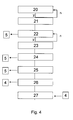
- Fig. 4 is a flowchart of a segment of the program for the controller 1.
- a first step 20 of the program segment decides whether or not an accident-occurrence indicating signal is received. When an accident-occurrence indicating signal is not received, the step 20 is repeated. On the other hand, when an accident-occurrence indicating signal is received, the program advances from the step 20 to a step 21.
- the step 21 feeds a signal of a connection requirement to the communication device 5. Thereby, the step 21 requires the communication device 5 to execute a step of establishing radio connection with the emergency center.
- Step 22 decides whether or not radio connection between the communication device 5 and the emergency center has been established by referring to information fed from the communication device 5. When radio connection has not yet been established, the step 22 is repeated. On the other hand, when radio connection has been established, the program advances from the step 22 to a step 23.
- the step 23 reads out the data of the current vehicle position from the memory.
- a step 24 following the step 23 feeds the data of the current vehicle position to the communication device 5.
- a step 25 subsequent to the step 24 controls the communication device 2, thereby transmitting the data of the current vehicle position from the communication device 2 to the emergency report receiving center by radio on a data communication basis. With the feed back of emergency center that the position data are well received controller goes to step 26 and start the video record. In step 27 the video record data are connected to the communication device 5 to be transferred to emergency center too.
- the communication device is a mobile communication device, a normal mobile phone for example, that is connected to the vehicle's security device.
- This connection is possible via diverse interfaces as a fixed car set for the mobile phone or a special retainer connected to the security device 6 or a Bluetooth interace.
- the controller trigger a number dial with a fixed emergency center call number.
- a bidirectional communication between passengers and the emergency center can be established.
- This solution has the advantage that the support persons at the emergency center can ask for details to improve the level of support.
- the mobile phone has an electrical powering system independent from the vehicle. In special cases an accident will interrupt electrical connections. If for example the interior mirror with is destroyed the communication using a GSM module 11 is impossible. In this case the mobile phone can at least establish a voice communication to emergency center.
- step 28 the video data transmitting is disconnected after a pre-defined time or after pre-defined numbers of frames and the bi directional voice connection is established.
- MMS multimedia messaging service
- MMS multimedia messaging service
- the advantage of the invention emergency system is that the communication devices are flexible.
- the emergency system works with each of the known or planned communication devices and makes the driver independent from the new development and from the need to adapt emergency system to a changed communication environment.
Landscapes
- Physics & Mathematics (AREA)
- General Physics & Mathematics (AREA)
- Engineering & Computer Science (AREA)
- Multimedia (AREA)
- Mobile Radio Communication Systems (AREA)
- Alarm Systems (AREA)
Abstract
Description
- This invention relates to an emergency reporting network system for vehicles such as automotive vehicles. This invention also relates to a security device used in an emergency reporting network system.
- A known emergency communication apparatus for a vehicle is automatically started when the vehicle causes an accident. The known apparatus can also be started when a trigger button is depressed by vehicle's driver (a user). After the start, the known apparatus calls an emergency report receiving center by radio and hence tries to connect with the center. When the radio connection with the center has been established, the known apparatus implements emergency data communication (or emergency speech communication) with the center.
From theUS 6337641 an emergency reporting apparatus for a vehicle is known. The emergency reporting apparatus comprises a communication device and means for, in cases where an emergency occurs in the vehicle, using the communication device to report the emergency to an emergency report receiving center. The emergency reporting apparatus informs a user of an operating condition of the communication device when the communication device is used by the first means. - According the known apparatus sent voice signals and sensor signals to be received at the receiving centre.
- The normal sensor data and potential voice data are insufficient, if in case of an accident a rescue operation should be started. For an efficient rescue planning a video image of the situation of the persons in vehicle is helpful.
- Generating video signals from the interior of a vehicle is also known. In the
EP1298013 a system to supervise the interior and to detect persons on the seats of the vehicle is disclosed. The video signal is used to avoid air back explosions around empty seats. The video signal is not used outside the vehicle but in the inside system to control the security features.
TheGB 2358325 - It is a first object of this invention to provide an improved emergency reporting network system able to receive vehicle interior images and to send them to an emergency centre.
- It is a second object of this invention to provide an improved security device in an emergency reporting network system installed in a car.
- The security device has the advantage that in case of accident better information can be provided to the emergency centre. The video camera allows sending the video data in case of accident to the centre, so that the emergency service teams have an overview about the situation of persons in the vehicle. This allows a better and well adapted deployment of resources as for example a helicopter or ambulances.
-
-
FIG. 1 is a block diagram of an emergency reporting apparatus according to a first embodiment of this invention. -
FIG.2 and 3 shows embodiments of the position of a video sensor. -
FIG. 4 is a flow diagram of the security system - An emergency system includes emergency device which are mounted as security device on vehicles respectively. The emergency system also includes an emergency centre which operates as a host apparatus and receives the emergency messages. The security device can be connected with the emergency centre via a radio communication network such as a mobile telephone network, a GSM or a UMTS, a EDGE network or another air interface network as a dedicated short range connection with a beacon system along the streets.
-
FIG. 1 shows a security device according to a first embodiment of this invention. The security device is at least partly hidden mounted on a vehicle such as an automotive vehicle. - As shown in
FIG. 1 asecurity device 6 includes amicrocontroller 1 , aGPS receiver device 2, anaccident detector 3, anvideo input device 4 and, and acommunication device 5. - The
accident detector 3 is connected to thecontroller 1. Thecontroller 1 is connected to theGPS receiver 2. Thecontroller 1 is also connected to thecommunication device 5, theaccident detector 3 and thevideo input device 4. - The
accident detector 3 includes a collision sensor for detecting a collision of the related vehicle with another object, or a crash sensor for detecting a crash of the related vehicle against another object. When theaccident detector 3 detects the occurrence of an accident caused by the related vehicle, theaccident detector 3 outputs an accident-occurrence indicating signal to thecontroller 1. Thus, theaccident detector 3 informs thecontroller 1 of the occurrence of an accident caused by the related vehicle. - The
controller 1 includes a microcomputer, a CPU, or a similar device having a combination of an input/output port, a signal processing section, a RAM, and a ROM and a memory. Thecontroller 1 operates in accordance with a program stored in the ROM. The memory is accessed by thecontroller 1. A signal representing the current position of the related vehicle is stored into the memory by thecontroller 1. The vehicle position signal can be read out from the memory by thecontroller 1.
The GPS (Global Positioning System)receiver 2 works as positioning sensor for substantially continuously detecting the current position of the related vehicle. TheGPS receiver 2 informs thecontroller 1 of the detected current position of the related vehicle. - The
communication device 5 includes a radio transceiver, a radio communication device, or a mobile telephone set which can be controlled by thecontroller 1. Thecommunication device 5 can output and feed a radio signal to the antenna. The radio signal is radiated by the antenna. The radiated radio signal can propagate to an emergency report receiving center (not shown). The antenna can receive a radio signal from the emergency report receiving center. The received radio signal is fed from the antenna to thecommunication device 5. In this way, thecommunication device 5 can communicate with the emergency center by radio. Furthermore, thecommunication device 5 can communicate with a base station of a communication network by radio. - The
video input senor 4 is a common CCD sensor with an internal possibility to reduce data by compression methods. A wide variety of methods are used to compress video streams. Video data contains spatial and temporal redundancy, making uncompressed video streams extremely inefficient. Broadly speaking, spatial redundancy is reduced by registering differences between parts of a single frame; this task is known as intra frame compression and is closely related to image compression. Likewise, temporal redundancy can be reduced by registering differences between frames; this task is known as inter frame compression, including motion compensation and other techniques. The most common modern standards are MPEG-2, used for DVD and satellite television, and MPEG-4. - The security device in
FIG. 1 operates as follows. TheGPS receiver 2 substantially continuously detects the current position of the related vehicle. TheGPS receiver 2 generates data of the detected current vehicle position. TheGPS receiver 2 outputs the data of the detected current vehicle position to thecontroller 1. TheGPS receiver 2 may further include a gyro-based direction sensor and a vehicle speed sensor. Thecontroller 1 writes the data of the current vehicle position into the memory. The current vehicle position data in the memory are updated in accordance with the lapse of time. - Upon the occurrence of an accident caused by the related vehicle, the
accident detector 3 outputs an accident-occurrence indicating signal to thecontroller 1.
Thecontroller 1 feeds a signal of a connection requirement to thecommunication device 5 in response to the accident-occurrence indicating signal. Thereby, thecontroller 1 requires thecommunication device 5 to execute a step of establishing radio connection with the emergency center. - The
communication device 5 generates a radio connection requirement signal in response to the connection requirement fed from thecontroller 1. Thecommunication device 2 outputs the radio connection-requirement signal to the antenna. The radio connection-requirement signal is radiated by the antenna before propagating to the emergency center. When the emergency center is unoccupied and is able to accept radio communication, the emergency report receiving center returns a radio answer signal in response to the radio connection-requirement signal. The radio answer signal is received by the antenna. The received radio answer signal is fed from the antenna to the communication device 52. The radio answer signal fed to thecommunication device 5 represents that radio connection between thecommunication device 5 and the emergency center has been established. Thecommunication device 5 informs thecontroller 1 of the establishment of radio connection between thecommunication device 5 and the emergency center. - Immediately after the
controller 1 is informed of the establishment of radio connection, thecontroller 1 reads out the data of the current vehicle position from the memory. Thecontroller 1 feeds the data of the current vehicle position to thecommunication device 5. Thecontroller 1 controls thecommunication device 5, thereby transmitting the data of the current vehicle position from thecommunication device 5 to the emergency center by radio on a data communication basis. - After this step or parallel to this process step the
controller 1 starts thevideo input sensor 4, which is a sleep mode.Video input sensor 4 records the pictures of the users of the vehicle and bring them into a compressed data form. The compressed data are fed to the controller and to thecommunication device 5. The communication device sent the compressed video data stream via the antenna to the emergency center. - In the case where the radio connection between the
communication device 5 and the emergency center is cut off, that is, in the case where thecommunication device 5 and the emergency center are disconnected from each other, thecommunication device 5 informs thecontroller 1 of the disconnection. The controller restart the program to establish a connection to emergency center again. -
FIG. 2 Shows an embodiment of the invention. An interiorrear view mirror 8 is installed in each vehicle. The interior mirror has a reflective surface7 in a bezel of plastic which established the housing of the interior mirror. The interior mirror includes avideo sensor 9 at a random position on or at the mirror. The position of the video sensor is defined by an optimized view of the sensor to allow seeing all passengers in one picture. An alternative position of thevideo sensor 9 is behind the reflecting surface which is in this case a semi transparent for the video sensor at least at the sensor's position. The use of ahidden video sensor 9 behind the reflecting surface is mainly recommended when a self dimming mirror is installed. -
Fig. 3 shows also an interior mirror. In addition in this embodiment aGPS module 10 and aGSM module 11 is installed in the interior mirror. Via themirror base 12 the electrical connections to the several modules and devices are possible. -
Fig. 4 is a flowchart of a segment of the program for thecontroller 1. Afirst step 20 of the program segment decides whether or not an accident-occurrence indicating signal is received. When an accident-occurrence indicating signal is not received, thestep 20 is repeated. On the other hand, when an accident-occurrence indicating signal is received, the program advances from thestep 20 to astep 21. - The
step 21 feeds a signal of a connection requirement to thecommunication device 5. Thereby, thestep 21 requires thecommunication device 5 to execute a step of establishing radio connection with the emergency center.
Step 22 decides whether or not radio connection between thecommunication device 5 and the emergency center has been established by referring to information fed from thecommunication device 5. When radio connection has not yet been established, thestep 22 is repeated. On the other hand, when radio connection has been established, the program advances from thestep 22 to astep 23. - The
step 23 reads out the data of the current vehicle position from the memory. Astep 24 following thestep 23 feeds the data of the current vehicle position to thecommunication device 5. Astep 25 subsequent to thestep 24 controls thecommunication device 2, thereby transmitting the data of the current vehicle position from thecommunication device 2 to the emergency report receiving center by radio on a data communication basis. With the feed back of emergency center that the position data are well received controller goes to step 26 and start the video record. Instep 27 the video record data are connected to thecommunication device 5 to be transferred to emergency center too. - In another embodiment of the invention the communication device is a mobile communication device, a normal mobile phone for example, that is connected to the vehicle's security device. This connection is possible via diverse interfaces as a fixed car set for the mobile phone or a special retainer connected to the
security device 6 or a Bluetooth interace. In case of emergency the controller trigger a number dial with a fixed emergency center call number. - In this embodiment of the invention a bidirectional communication between passengers and the emergency center can be established. This solution has the advantage that the support persons at the emergency center can ask for details to improve the level of support. In addition the mobile phone has an electrical powering system independent from the vehicle. In special cases an accident will interrupt electrical connections. If for example the interior mirror with is destroyed the communication using a
GSM module 11 is impossible. In this case the mobile phone can at least establish a voice communication to emergency center. - In detail the program running on the
controller 1 is modified. Thecommunication device 5 is activated instep 22. In this case the controller triggers the mobile phone to dial the emergency center number. An additional step is also established. Afterstep 27 in which the video record data are connected to thecommunication device 5 to be transferred to emergency center, step 28 follows. In step 28 the video data transmitting is disconnected after a pre-defined time or after pre-defined numbers of frames and the bi directional voice connection is established. - Another preferred embodiment replaces the sensing of a full video stream by using a video picture or less expensive a photo sensor to sent out single pictures succeeding recorded.
Both video streams or single pictures are sent by using multimedia messaging service MMS.MMS is a part of the 3GPP (third Generation Partnership Program) standards developed for GSM and UMTS communication. MMS-enabled mobile phones enable subscribers to compose and send messages with one or more multimedia parts. Multimedia parts may include text, images, audio and video. These content types should conform to the MMS Standards. For example a phone can send an MPEG-4 video in AVI format, but the other party who is receiving the MMS may not be able to interpret it. To avoid this, all mobiles should follow the standards defined by OMA. Mobile phones with built-in or attached cameras, or with built-in MP3 players are very likely to also have an MMS messaging client-a software program that interacts with the mobile subscriber to compose, address, send, receive, and view MMS messages. - The advantage of the invention emergency system is that the communication devices are flexible. The emergency system works with each of the known or planned communication devices and makes the driver independent from the new development and from the need to adapt emergency system to a changed communication environment.
Claims (10)
- A security system for a vehicle including a remote emergency centre reachable by a mobile connection, a security device (6) installed in the vehicle including a controller (1), a GPS receiver (2), at least one accident sensor (3), at least one video sensor (4,9) and a radio communication mean (5), wherein the radio communication mean (5) is sending in case of an accident, characterized in that the radio communication mean (2) enables the transmission of picture information of the vehicle interior to the emergency centre.
- A security system according claim 1 characterized in that the at least one video sensor (9) is placed in the interior mirror of the vehicle.
- A security system according claim 2 characterized in that the interior mirror of the vehicle comprise the GPS receiver (10) and a radio communication mean (11).
- A security system according claim 1 characterized in that the video signal is a sent as a video stream.
- A security system according claim 1 characterized in that the video signal is sent in a MMS format.
- A security system according claim 1 characterized in that the video sensor is replaced by a photo sensor.
- A security system according claim 1 characterized in that the communication mean (5) establishes a voice communication.
- A security system according claim 1 characterized in that the communication device is a mobile phone.
- Method to run a security system in a vehicle including a security device installed in the vehicle with a controller, a GPS receiver, at least one accident sensor, at least one video sensor and a radio communication mean, wherein the radio communication mean is sending in case of an accident, characterized by the steps:Deciding that an accident was happening (20)Connecting the communication device (21)Establishing a radio communication (22)Reading the position data of the vehicle (23)Sending the position to emergency center (24)Controlling the communication (25)Starting video record (26)Sending video data (27)
- Method to run a security system according claim 9, replacing video sensors by photo sensors and video data by picture data.
Priority Applications (3)
| Application Number | Priority Date | Filing Date | Title |
|---|---|---|---|
| DE602008005700T DE602008005700D1 (en) | 2008-01-15 | 2008-01-15 | Emergency system for a vehicle |
| EP08100482A EP2080674B1 (en) | 2008-01-15 | 2008-01-15 | Emergency system for a vehicle |
| US12/353,525 US20090183209A1 (en) | 2008-01-15 | 2009-01-14 | Emergency system for a vehicle |
Applications Claiming Priority (1)
| Application Number | Priority Date | Filing Date | Title |
|---|---|---|---|
| EP08100482A EP2080674B1 (en) | 2008-01-15 | 2008-01-15 | Emergency system for a vehicle |
Publications (2)
| Publication Number | Publication Date |
|---|---|
| EP2080674A1 true EP2080674A1 (en) | 2009-07-22 |
| EP2080674B1 EP2080674B1 (en) | 2011-03-23 |
Family
ID=39494574
Family Applications (1)
| Application Number | Title | Priority Date | Filing Date |
|---|---|---|---|
| EP08100482A Expired - Fee Related EP2080674B1 (en) | 2008-01-15 | 2008-01-15 | Emergency system for a vehicle |
Country Status (3)
| Country | Link |
|---|---|
| US (1) | US20090183209A1 (en) |
| EP (1) | EP2080674B1 (en) |
| DE (1) | DE602008005700D1 (en) |
Cited By (2)
| Publication number | Priority date | Publication date | Assignee | Title |
|---|---|---|---|---|
| EP2743141A1 (en) * | 2012-12-12 | 2014-06-18 | Volvo Car Corporation | Control arrangement for vehicle |
| US9055425B2 (en) | 2012-09-27 | 2015-06-09 | Nokia Technologies Oy | Method and apparatus for enhancing emergency calling with mobile devices |
Families Citing this family (9)
| Publication number | Priority date | Publication date | Assignee | Title |
|---|---|---|---|---|
| US8239905B2 (en) * | 2009-01-22 | 2012-08-07 | Microsoft Corporation | Lecture capture and broadcast system |
| CN102404539A (en) * | 2010-09-14 | 2012-04-04 | 北京首科软件及系统集成有限责任公司 | Novel mobile and printable video law enforcement terminal system |
| US12122299B2 (en) | 2012-01-24 | 2024-10-22 | SMR Patents S.à.r.l. | External rearview device, external rearview device kit and vehicle |
| US11273764B2 (en) * | 2012-01-24 | 2022-03-15 | SMR Patents S.à.r.l. | External rearview device, external rearview device kit and vehicle |
| GB201219230D0 (en) * | 2012-10-25 | 2012-12-12 | Nycz Krzysztof M | Lifesaver - both a smartphone application and a car modification/kit compatible together to save human lives |
| CN108900600A (en) * | 2018-06-27 | 2018-11-27 | 中南大学湘雅医院 | Intelligent digital ambulance system |
| US11615200B2 (en) * | 2020-04-14 | 2023-03-28 | Toyota Motor North America, Inc. | Providing video evidence |
| US11450099B2 (en) | 2020-04-14 | 2022-09-20 | Toyota Motor North America, Inc. | Video accident reporting |
| US11508189B2 (en) | 2020-04-14 | 2022-11-22 | Toyota Motor North America, Inc. | Processing of accident report |
Citations (4)
| Publication number | Priority date | Publication date | Assignee | Title |
|---|---|---|---|---|
| GB2358325A (en) | 1999-12-20 | 2001-07-18 | Nicholas Kennedy | A mobile information system which displays live information from a moving object as an internet or other broadcast |
| US6337641B1 (en) | 1999-01-29 | 2002-01-08 | Matsushita Electric Industrial Co., Ltd. | Emergency reporting system and terminal apparatus therein |
| EP1298013A2 (en) | 2001-09-27 | 2003-04-02 | Kabushiki Kaisha Tokai Rika Denki Seisakusho | Passenger compartment monitoring apparatus |
| US20050230947A1 (en) * | 2004-04-16 | 2005-10-20 | Hon Hai Precision Industry Co., Ltd. | Electronic safety device for a motor vehicle |
Family Cites Families (17)
| Publication number | Priority date | Publication date | Assignee | Title |
|---|---|---|---|---|
| US5808564A (en) * | 1992-02-06 | 1998-09-15 | Simms Security Corp. | Personal security system with remote activation |
| US5223844B1 (en) * | 1992-04-17 | 2000-01-25 | Auto Trac Inc | Vehicle tracking and security system |
| US6172613B1 (en) * | 1998-02-18 | 2001-01-09 | Donnelly Corporation | Rearview mirror assembly incorporating vehicle information display |
| US6389340B1 (en) * | 1998-02-09 | 2002-05-14 | Gary A. Rayner | Vehicle data recorder |
| US6545601B1 (en) * | 1999-02-25 | 2003-04-08 | David A. Monroe | Ground based security surveillance system for aircraft and other commercial vehicles |
| WO2001064481A2 (en) * | 2000-03-02 | 2001-09-07 | Donnelly Corporation | Video mirror systems incorporating an accessory module |
| US6522267B2 (en) * | 2000-05-17 | 2003-02-18 | Omega Patents, L.L.C. | Vehicle tracker conserving codes and related methods |
| JP4293723B2 (en) * | 2000-11-01 | 2009-07-08 | 日産自動車株式会社 | Vehicle information presentation device |
| US6559769B2 (en) * | 2001-10-01 | 2003-05-06 | Eric Anthony | Early warning real-time security system |
| JP3951231B2 (en) * | 2002-12-03 | 2007-08-01 | オムロン株式会社 | Safe travel information mediation system, safe travel information mediation device used therefor, and safe travel information confirmation method |
| US7299127B2 (en) * | 2003-05-02 | 2007-11-20 | Sony Corporation | Shared oscillator for vehicle mirror display |
| JP2005112043A (en) * | 2003-10-03 | 2005-04-28 | Nissan Motor Co Ltd | Emergency call system for vehicles |
| US20050186941A1 (en) * | 2004-02-10 | 2005-08-25 | General Motors Corporation | Verification of telematic unit in fail to voice situation |
| US20050185052A1 (en) * | 2004-02-25 | 2005-08-25 | Raisinghani Vijay S. | Automatic collision triggered video system |
| KR20060014765A (en) * | 2004-08-12 | 2006-02-16 | 주식회사 현대오토넷 | Emergency rescue service system and method using telematics system |
| US20070100521A1 (en) * | 2005-10-31 | 2007-05-03 | Eric Grae | Reporting information related to a vehicular accident |
| JP4872733B2 (en) * | 2007-03-16 | 2012-02-08 | 株式会社デンソー | In-vehicle emergency call device |
-
2008
- 2008-01-15 EP EP08100482A patent/EP2080674B1/en not_active Expired - Fee Related
- 2008-01-15 DE DE602008005700T patent/DE602008005700D1/en active Active
-
2009
- 2009-01-14 US US12/353,525 patent/US20090183209A1/en not_active Abandoned
Patent Citations (4)
| Publication number | Priority date | Publication date | Assignee | Title |
|---|---|---|---|---|
| US6337641B1 (en) | 1999-01-29 | 2002-01-08 | Matsushita Electric Industrial Co., Ltd. | Emergency reporting system and terminal apparatus therein |
| GB2358325A (en) | 1999-12-20 | 2001-07-18 | Nicholas Kennedy | A mobile information system which displays live information from a moving object as an internet or other broadcast |
| EP1298013A2 (en) | 2001-09-27 | 2003-04-02 | Kabushiki Kaisha Tokai Rika Denki Seisakusho | Passenger compartment monitoring apparatus |
| US20050230947A1 (en) * | 2004-04-16 | 2005-10-20 | Hon Hai Precision Industry Co., Ltd. | Electronic safety device for a motor vehicle |
Cited By (2)
| Publication number | Priority date | Publication date | Assignee | Title |
|---|---|---|---|---|
| US9055425B2 (en) | 2012-09-27 | 2015-06-09 | Nokia Technologies Oy | Method and apparatus for enhancing emergency calling with mobile devices |
| EP2743141A1 (en) * | 2012-12-12 | 2014-06-18 | Volvo Car Corporation | Control arrangement for vehicle |
Also Published As
| Publication number | Publication date |
|---|---|
| EP2080674B1 (en) | 2011-03-23 |
| DE602008005700D1 (en) | 2011-05-05 |
| US20090183209A1 (en) | 2009-07-16 |
Similar Documents
| Publication | Publication Date | Title |
|---|---|---|
| EP2080674B1 (en) | Emergency system for a vehicle | |
| US7580697B2 (en) | Method and emergency call device for triggering an emergency call from a vehicle | |
| JP2002166803A (en) | Communication system for vehicle, communication device for vehicle, vehicle, communication method, and computer-readable storage medium | |
| US20110143751A1 (en) | Flexible Telematics System and Method for Providing Telematics to a Vehicle | |
| EP3480060B1 (en) | A method of integrating cameras in vehicles, corresponding system, circuit, kit and vehicle | |
| JP2008244674A (en) | Wireless terminal, in-vehicle wireless terminal holder, server, and drive recorder system | |
| EP3518200A1 (en) | Method for motorcycle accident detection and notification | |
| CN106080516A (en) | A kind of method and apparatus that vehicle is monitored | |
| JP2011171798A (en) | Mobile phone functioning as drive recorder, program and drive recording method | |
| US20170171733A1 (en) | Vehicle head unit, user terminal and method for notification of emergency state of vehicle | |
| JP2010114588A (en) | Method of reporting accident situation using cellular phone terminal, cellular phone terminal having accident information reporting function, and program | |
| EP1143752A1 (en) | Mobile telephone with silent mode for emergencies | |
| KR20140128840A (en) | Image-processing Apparatus for Car and Method of Controlling The Same | |
| CN118354295A (en) | Vehicle communication method, related device and communication system | |
| JP3960148B2 (en) | Video phone system | |
| KR101477913B1 (en) | Black box for vehicle having event notifying function over wifi communication | |
| CN208836130U (en) | A kind of talkback unit and system | |
| KR20050102540A (en) | Response mode conversion apparatus and method for mobile station | |
| JP2008236385A (en) | Portable terminal device | |
| JP2004330965A (en) | Vehicle interior pet monitoring system | |
| US20150116491A1 (en) | Private and automatic transmission of photograph via occupant's cell phone following impact event | |
| KR20050112932A (en) | Method for furnishing the information of car accident using mobile terminal | |
| CN120956390B (en) | Communication method, device, vehicle, terminal, chip and storage medium | |
| JP7829799B2 (en) | Information processing device | |
| JP7685071B2 (en) | COMMUNICATION SYSTEM, INFORMATION PROCESSING APPARATUS, INFORMATION PROCESSING METHOD, PROGRAM, AND RECORDING MEDIUM |
Legal Events
| Date | Code | Title | Description |
|---|---|---|---|
| PUAI | Public reference made under article 153(3) epc to a published international application that has entered the european phase |
Free format text: ORIGINAL CODE: 0009012 |
|
| 17P | Request for examination filed |
Effective date: 20080715 |
|
| AK | Designated contracting states |
Kind code of ref document: A1 Designated state(s): AT BE BG CH CY CZ DE DK EE ES FI FR GB GR HR HU IE IS IT LI LT LU LV MC MT NL NO PL PT RO SE SI SK TR |
|
| AX | Request for extension of the european patent |
Extension state: AL BA MK RS |
|
| RAP1 | Party data changed (applicant data changed or rights of an application transferred) |
Owner name: SMR PATENTS S.A.R.L. |
|
| AKX | Designation fees paid |
Designated state(s): AT BE BG CH CY CZ DE DK EE ES FI FR GB GR HR HU IE IS IT LI LT LU LV MC MT NL NO PL PT RO SE SI SK TR |
|
| AXX | Extension fees paid |
Extension state: RS Payment date: 20100122 Extension state: MK Payment date: 20100122 Extension state: BA Payment date: 20100122 Extension state: AL Payment date: 20100122 |
|
| GRAP | Despatch of communication of intention to grant a patent |
Free format text: ORIGINAL CODE: EPIDOSNIGR1 |
|
| RBV | Designated contracting states (corrected) |
Designated state(s): DE FR GB |
|
| GRAS | Grant fee paid |
Free format text: ORIGINAL CODE: EPIDOSNIGR3 |
|
| GRAA | (expected) grant |
Free format text: ORIGINAL CODE: 0009210 |
|
| AK | Designated contracting states |
Kind code of ref document: B1 Designated state(s): DE FR GB |
|
| REG | Reference to a national code |
Ref country code: GB Ref legal event code: FG4D |
|
| REF | Corresponds to: |
Ref document number: 602008005700 Country of ref document: DE Date of ref document: 20110505 Kind code of ref document: P |
|
| REG | Reference to a national code |
Ref country code: DE Ref legal event code: R096 Ref document number: 602008005700 Country of ref document: DE Effective date: 20110505 |
|
| PLBE | No opposition filed within time limit |
Free format text: ORIGINAL CODE: 0009261 |
|
| STAA | Information on the status of an ep patent application or granted ep patent |
Free format text: STATUS: NO OPPOSITION FILED WITHIN TIME LIMIT |
|
| 26N | No opposition filed |
Effective date: 20111227 |
|
| REG | Reference to a national code |
Ref country code: DE Ref legal event code: R097 Ref document number: 602008005700 Country of ref document: DE Effective date: 20111227 |
|
| PGFP | Annual fee paid to national office [announced via postgrant information from national office to epo] |
Ref country code: FR Payment date: 20120206 Year of fee payment: 5 |
|
| PGFP | Annual fee paid to national office [announced via postgrant information from national office to epo] |
Ref country code: DE Payment date: 20120123 Year of fee payment: 5 |
|
| PGFP | Annual fee paid to national office [announced via postgrant information from national office to epo] |
Ref country code: GB Payment date: 20120120 Year of fee payment: 5 |
|
| REG | Reference to a national code |
Ref country code: DE Ref legal event code: R082 Ref document number: 602008005700 Country of ref document: DE Representative=s name: JONES DAY RECHTSANWAELTE PATENTANWAELTE, DE |
|
| GBPC | Gb: european patent ceased through non-payment of renewal fee |
Effective date: 20130115 |
|
| REG | Reference to a national code |
Ref country code: FR Ref legal event code: ST Effective date: 20130930 |
|
| PG25 | Lapsed in a contracting state [announced via postgrant information from national office to epo] |
Ref country code: DE Free format text: LAPSE BECAUSE OF NON-PAYMENT OF DUE FEES Effective date: 20130801 |
|
| REG | Reference to a national code |
Ref country code: DE Ref legal event code: R119 Ref document number: 602008005700 Country of ref document: DE Effective date: 20130801 |
|
| PG25 | Lapsed in a contracting state [announced via postgrant information from national office to epo] |
Ref country code: FR Free format text: LAPSE BECAUSE OF NON-PAYMENT OF DUE FEES Effective date: 20130131 Ref country code: GB Free format text: LAPSE BECAUSE OF NON-PAYMENT OF DUE FEES Effective date: 20130115 |