EP2080631B1 - Method of drumhead imaging - Google Patents
Method of drumhead imaging Download PDFInfo
- Publication number
- EP2080631B1 EP2080631B1 EP08251094A EP08251094A EP2080631B1 EP 2080631 B1 EP2080631 B1 EP 2080631B1 EP 08251094 A EP08251094 A EP 08251094A EP 08251094 A EP08251094 A EP 08251094A EP 2080631 B1 EP2080631 B1 EP 2080631B1
- Authority
- EP
- European Patent Office
- Prior art keywords
- image
- substrate
- membrane
- comprised
- providing
- Prior art date
- Legal status (The legal status is an assumption and is not a legal conclusion. Google has not performed a legal analysis and makes no representation as to the accuracy of the status listed.)
- Active
Links
Images


Classifications
-
- B—PERFORMING OPERATIONS; TRANSPORTING
- B41—PRINTING; LINING MACHINES; TYPEWRITERS; STAMPS
- B41M—PRINTING, DUPLICATING, MARKING, OR COPYING PROCESSES; COLOUR PRINTING
- B41M5/00—Duplicating or marking methods; Sheet materials for use therein
- B41M5/025—Duplicating or marking methods; Sheet materials for use therein by transferring ink from the master sheet
- B41M5/0256—Duplicating or marking methods; Sheet materials for use therein by transferring ink from the master sheet the transferable ink pattern being obtained by means of a computer driven printer, e.g. an ink jet or laser printer, or by electrographic means
-
- G—PHYSICS
- G10—MUSICAL INSTRUMENTS; ACOUSTICS
- G10D—STRINGED MUSICAL INSTRUMENTS; WIND MUSICAL INSTRUMENTS; ACCORDIONS OR CONCERTINAS; PERCUSSION MUSICAL INSTRUMENTS; AEOLIAN HARPS; SINGING-FLAME MUSICAL INSTRUMENTS; MUSICAL INSTRUMENTS NOT OTHERWISE PROVIDED FOR
- G10D13/00—Percussion musical instruments; Details or accessories therefor
- G10D13/10—Details of, or accessories for, percussion musical instruments
- G10D13/24—Material for manufacturing percussion musical instruments; Treatment of the material
Definitions
- the present invention relates generally to the area of musical instruments. More particularly, the invention is directed to a method for forming a dye sublimation image of a simulated animal skin or some other graphic in a vibrating membrane employed in a musical instrument.
- drumheads used for timpani drums and for ethnic drums including, for example, congas, bongos, Djembes and Doumbeks, which in the past have used heads made from actual animal skins. Synthetic drumheads then replaced the animal skins to improve the longevity of the heads, which resisted moisture brought about by changing climate and other weather conditions.
- US-A1-2003/017 311 describes sublistatic printing on solid plastic objects, e.g. guitars or woodwinds.
- the technology of the present invention provides the ability to apply a graphic to a drumhead, including one that so realistically simulates a genuine animal skin such as the timpani and ethnic drums mentioned earlier, whilst maintaining and even enhancing the quality of the synthetic drumhead sounds in the process. Except for some small, though important, advances in the art involving the use of simulated animal skins or other kinds of graphics with synthetic heads, nothing, until now, has succeeded in achieving a method for producing a synthetic drumhead with the superior musical sound qualities and the delamination and wear resistant properties of the present invention.
- the present invention results in a significantly superior dye sublimation imaging method for drumhead membranes than heretofore were unattainable in the prior art.
- An embodiment of the present invention provides a method for forming a dye sublimation image in a vibrating membrane employed in a musical instrument comprising the steps of: providing an image, digitally prepared or otherwise, consisting of a simulated animal skin or another form of graphic; printing the image on a substrate employing a heat transfer ink dye; joining the substrate with the printed image with a sheet of a gas permeable membrane having a plurality of surface pores and vibrating and musical note producing capability; applying a combination of heat and pressure to the joined substrate with the printed image and the membrane to cause the individual surface pores to expand to enable the dye to gasify and permeate the surface pores to transfer the image; and, cooling the membrane to enable the surface pores to seal closed and encase the image within the surface of the membrane to protect against delamination and wear when the membrane vibrates which results from the intense and constant pounding of a drumstick, a mallet, a person's hand or some other rigid-like object.
- Embodiments of the present invention provide an improved method to more effectively and permanently form a dye sublimation image within a vibrating membrane employed in a musical instrument.
- embodiments of the present invention provide an improved method to more effectively and permanently form a dye sublimation image within a vibrating membrane that can resist normal delamination and wear when constantly pounded by a rigid object.
- the tonal qualities produced by a musical instrument can be enhanced, the visual qualities of the musical instrument can be enhanced, and/or the image of an authentic animal skin can be produced.
- Embodiments of the present invention enable the mass production of a variety of musical drumheads with integrated dye sublimation images, using a technique that is easy and cost effective to use.
- FIGS. 1 through 6 An embodiment of the present invention will be described in more detail with reference to the preferred embodiment shown in FIGS. 1 through 6 .
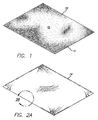
- FIG. 1 is a perspective view of a transfer substrate 10 typically comprised of a standard presentation grade paper or any other suitable medium.
- a desired image 12 such as a simulated animal skin or some other graphic, is prepared using any conventional method or means, including, for example, a computer.
- the computer instructs a printer to print a digital image 12 onto the transfer substrate 10, in this example, a standard presentation grade paper, using standard dye-sublimation or heat transfer inks 11.
- the paper onto which image 12 is transferred simply acts as a carrier for the inked image, which is eventually transferred to another, usually more permanent substrate 14.
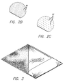
- FIG. 2A is a perspective view of permanent substrate 14, typically a polyester membrane for the purpose of this embodiment, but may be comprised of any other suitable material, synthetic or otherwise.
- Transfer substrate 10 and permanent substrate 14 are joined and then exposed concurrently to heat between 250 and 394 degrees Fahrenheit and pressure between 20 and 100 PSI for a period of 30 seconds to 3 minutes. Variance in the temperature, pressure and time depend on the material composition of the substrates.
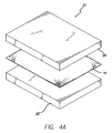
- FIGS 2B and 2C are cross-sections of substrate 14 shown in FIG. 2A .
- FIG 2B shows multiple closed surface pores 16 in substrate 14 before heat 18 is applied and the image transfer process begins.
- FIG. 2C shows multiple open surface pores 17, but open prepared to receive the transfer of image 12 from transfer substrate 10.
- FIG. 3 shows transfer substrate 10 with printed graphic image 12 on the bottom with permanent substrate 14, again, with this embodiment a polyester membrane, being laid over the top.
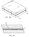
- FIG. 4A shows the preferred embodiment of the apparatus 21 used for performing the method of the present invention. Shown are two rectangular platen, including top platen 20 and bottom platen 22, and the joined substrates 10 and 14 in between.
- An appropriate press apparatus (not shown) is used to cause platen 20 and platen 22 to converge and apply the necessary pressure 24 to joined substrates 10 and 14 ( FIG. 4B ).
- a heat source using any conventional means compels the transfer of heat 18 through platen 20 and platen 22 into substrates 10 and 14 to cause closed surface pores 16 in substrate 14 to open allowing ink 11 from printed image 12 in substrate 10 to permeate ( FIGS. 5A-5E ). Heat 18, along with required pressure 24, is sufficiently intense to permit ink 11 to bypass a liquid state and gasify instead.
- ink 11 permeates open surface pores 17 in substrate 14 and then open surface pores 17 are fused.
- substrate 14 with the integrated transferred image is allowed to cool permitting, in turn, now closed surface pores 16 within substrate 14 to cure and permanently encase image 12 ( FIG. 5F ). This ensures that image 12, despite the amount and intensity of the pounding it receives when the drumhead membrane is struck, is delamination and weather resistant.
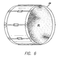
- FIG. 6 is an example of imbued image 12 within the vibrating membrane or head 26 of a bass drum 28.
Landscapes
- Engineering & Computer Science (AREA)
- General Engineering & Computer Science (AREA)
- Physics & Mathematics (AREA)
- Acoustics & Sound (AREA)
- Multimedia (AREA)
- Decoration By Transfer Pictures (AREA)
- Thermal Transfer Or Thermal Recording In General (AREA)
- Electronic Switches (AREA)
- Printing Methods (AREA)
- Coloring (AREA)
- Pinball Game Machines (AREA)
- Display Devices Of Pinball Game Machines (AREA)
Description
- The present invention relates generally to the area of musical instruments. More particularly, the invention is directed to a method for forming a dye sublimation image of a simulated animal skin or some other graphic in a vibrating membrane employed in a musical instrument.
- The use of graphic art on musical drumheads is well known in the prior art. Images on drumheads are used for all kinds of purposes, including, for example, simple aesthetics, to create a theme or personality for a musician or a band, or for general promotion. Examples of prior art graphic applications include silk screening, hand painting, stenciling or attaching the graphic born on a separate medium with adhesive. The dye sublimation process itself is also not new in the art, and has been used to apply a large assortment of graphic images of various colors and designs to drumheads of all kinds and sizes, including, without limitation, tom-toms, snares and bass drums.
- Screened, stenciled or painted images are applied directly to the surface of the membrane and, thus, are inclined to peel or wear off over time due to the constant pounding of drumsticks, exposure to weather and other factors. The use of an adhesive backing introduces still another physical medium to the membrane, which tends to deaden its sound. With regard to all these applications, in addition to problems with delamination of the graphic from the substrate, the musical sound qualities and durability of the drumhead are severely undermined. Even with the dye sublimation process, there are instances when the application of a graphic image to a drumhead membrane, though aesthetically appealing, will produce a sound of inferior quality due to the inferiority of or other problems associated with the process itself. This concern is especially high in regard to drumheads used for timpani drums and for ethnic drums, including, for example, congas, bongos, Djembes and Doumbeks, which in the past have used heads made from actual animal skins. Synthetic drumheads then replaced the animal skins to improve the longevity of the heads, which resisted moisture brought about by changing climate and other weather conditions.
-
US-A1-2003/017 311 describes sublistatic printing on solid plastic objects, e.g. guitars or woodwinds. - Particular and preferred aspects of the present invention are set out in the accompanying independent and dependent claims.
- The technology of the present invention provides the ability to apply a graphic to a drumhead, including one that so realistically simulates a genuine animal skin such as the timpani and ethnic drums mentioned earlier, whilst maintaining and even enhancing the quality of the synthetic drumhead sounds in the process. Except for some small, though important, advances in the art involving the use of simulated animal skins or other kinds of graphics with synthetic heads, nothing, until now, has succeeded in achieving a method for producing a synthetic drumhead with the superior musical sound qualities and the delamination and wear resistant properties of the present invention. The present invention results in a significantly superior dye sublimation imaging method for drumhead membranes than heretofore were unattainable in the prior art.
- An embodiment of the present invention provides a method for forming a dye sublimation image in a vibrating membrane employed in a musical instrument comprising the steps of: providing an image, digitally prepared or otherwise, consisting of a simulated animal skin or another form of graphic; printing the image on a substrate employing a heat transfer ink dye; joining the substrate with the printed image with a sheet of a gas permeable membrane having a plurality of surface pores and vibrating and musical note producing capability; applying a combination of heat and pressure to the joined substrate with the printed image and the membrane to cause the individual surface pores to expand to enable the dye to gasify and permeate the surface pores to transfer the image; and, cooling the membrane to enable the surface pores to seal closed and encase the image within the surface of the membrane to protect against delamination and wear when the membrane vibrates which results from the intense and constant pounding of a drumstick, a mallet, a person's hand or some other rigid-like object.
- Embodiments of the present invention provide an improved method to more effectively and permanently form a dye sublimation image within a vibrating membrane employed in a musical instrument.
- More particularly, embodiments of the present invention provide an improved method to more effectively and permanently form a dye sublimation image within a vibrating membrane that can resist normal delamination and wear when constantly pounded by a rigid object.
- Using the technique of embodiments of the present invention, the tonal qualities produced by a musical instrument can be enhanced, the visual qualities of the musical instrument can be enhanced, and/or the image of an authentic animal skin can be produced.
- Embodiments of the present invention enable the mass production of a variety of musical drumheads with integrated dye sublimation images, using a technique that is easy and cost effective to use.
- Further particular and preferred aspects of the present invention are set out in the accompanying independent and dependent claims. Features of the dependent claims may be combined with features of the independent claims as appropriate, and in combinations other than those explicitly set out in the claims.
- The present invention will be described further, by way of example only, with reference to preferred embodiments thereof as illustrated in the accompanying drawings, in which:
-
FIG. 1 is a perspective view of a transfer substrate with a printed graphic of a simulated animal skin in accordance with the method of an embodiment of the present invention. -
FIG. 2A is a perspective view of the membrane substrate in accordance with the method of an embodiment of the present invention. -
FIG. 2B is a cross-section of the membrane substrate with closed surface pores as shown and defined bycircular line 2B inFIG. 2A . -
FIG. 2C is a cross-section of a version of the membrane substrate shown and defined bycircular line 2B inFIG. 2A with open surface pores. -
FIG. 3 is a perspective view of the transfer substrate with the graphic image (bottom) being covered by the membrane substrate in accordance with the method of an embodiment of the present invention. -
FIG. 4A is a perspective view of the press and heating apparatus consisting of top and bottom platen and conforming substrates in between for performing the method according to an embodiment of the present invention. -
FIG. 4B is a perspective view of the apparatus consisting of top and bottom platen pressing the conforming substrates in between for performing the method of an embodiment of the present invention. -
FIG. 5A is a cross-sectional view of the apparatus and substrates shown inFIG. 4B for performing the method of an embodiment of the present invention. -
FIG. 5B is a cross-sectional view of another embodiment of the apparatus and substrates shown inFIG. 4B used for performing a further step of the method of an embodiment of the present invention. -
FIG. 5C is a cross-sectional view of another embodiment of the apparatus and substrates shown inFIG. 4B used for performing a further step of the method of an embodiment of the present invention. -
FIG. 5D is a cross-sectional view of another embodiment of the apparatus and substrates shown inFIG. 4B used for performing a further step of the method of an embodiment of the present invention. -
FIG. 5E is a cross-sectional view of another embodiment of the substrates shown inFIG. 4B used for performing a further step of the method of an embodiment of the present invention. -
FIG. 5F is a perspective view of the membrane substrate with integrated encased image in accordance with the method of an embodiment of the present invention. -
FIG. 6 is a perspective view of a transferred image of a simulated animal skin on a bass drum produced in accordance with the method of an embodiment of the present invention. - An embodiment of the present invention will be described in more detail with reference to the preferred embodiment shown in
FIGS. 1 through 6 . -
FIG. 1 is a perspective view of atransfer substrate 10 typically comprised of a standard presentation grade paper or any other suitable medium. A desiredimage 12, such as a simulated animal skin or some other graphic, is prepared using any conventional method or means, including, for example, a computer. Employing this method, the computer instructs a printer to print adigital image 12 onto thetransfer substrate 10, in this example, a standard presentation grade paper, using standard dye-sublimation orheat transfer inks 11. The paper onto whichimage 12 is transferred simply acts as a carrier for the inked image, which is eventually transferred to another, usually morepermanent substrate 14. -
FIG. 2A is a perspective view ofpermanent substrate 14, typically a polyester membrane for the purpose of this embodiment, but may be comprised of any other suitable material, synthetic or otherwise.Transfer substrate 10 andpermanent substrate 14 are joined and then exposed concurrently to heat between 250 and 394 degrees Fahrenheit and pressure between 20 and 100 PSI for a period of 30 seconds to 3 minutes. Variance in the temperature, pressure and time depend on the material composition of the substrates. -
FIGS 2B and 2C are cross-sections ofsubstrate 14 shown inFIG. 2A .FIG 2B shows multiple closed surface pores 16 insubstrate 14 beforeheat 18 is applied and the image transfer process begins.FIG. 2C shows multiple open surface pores 17, but open prepared to receive the transfer ofimage 12 fromtransfer substrate 10. -
FIG. 3 showstransfer substrate 10 with printedgraphic image 12 on the bottom withpermanent substrate 14, again, with this embodiment a polyester membrane, being laid over the top. -
FIG. 4A shows the preferred embodiment of theapparatus 21 used for performing the method of the present invention. Shown are two rectangular platen, includingtop platen 20 andbottom platen 22, and the joinedsubstrates platen 20 andplaten 22 to converge and apply thenecessary pressure 24 to joinedsubstrates 10 and 14 (FIG. 4B ). A heat source using any conventional means (also not shown) compels the transfer ofheat 18 throughplaten 20 andplaten 22 intosubstrates substrate 14 to open allowingink 11 from printedimage 12 insubstrate 10 to permeate (FIGS. 5A-5E ).Heat 18, along with requiredpressure 24, is sufficiently intense to permitink 11 to bypass a liquid state and gasify instead. With sufficient pressure,ink 11 permeates open surface pores 17 insubstrate 14 and then open surface pores 17 are fused. When the transfer ofimage 12 is complete,substrate 14 with the integrated transferred image is allowed to cool permitting, in turn, now closed surface pores 16 withinsubstrate 14 to cure and permanently encase image 12 (FIG. 5F ). This ensures thatimage 12, despite the amount and intensity of the pounding it receives when the drumhead membrane is struck, is delamination and weather resistant. -
FIG. 6 is an example of imbuedimage 12 within the vibrating membrane orhead 26 of abass drum 28. - Other alternatives available for performing the method of embodiments of the present invention include the use of heated and pinch rollers (not shown) similar to a steam press or a lamination machine in lieu of
platen 20 andplaten 22 described herein.
Claims (11)
- A method for forming a dye sublimation image (12) in a vibrating membrane (14) employed in a musical instrument comprising the steps of;
providing an image;
printing said image (12) onto a first substrate (10) employing a heat transfer ink dye; joining said first substrate (10) and said printed image (12) with a sheet of a gas permeable membrane having a plurality of surface pores and a vibrating and musical note producing capability;
applying a combination of heat and pressure to said joined first substrate (10) with said printed image (12) and said membrane (14) to cause said individual surface pores to expand to enable said dye to gasify and permeate said surface pores to transfer said image; and,
cooling said membrane (14) to enable said surface pores to seal over and encase said image to integrate said image (12) with said membrane in delamination and wear resistant relation. - The method of claim 1, including the step of providing as the gas permeable membrane (14) a membrane comprised of polyester material.
- The method of claim 1 or claim 2, wherein the image (12) is comprised of a simulated animal skin.
- The method of claim 1 or claim 2, wherein the image (12) is comprised of graphic art.
- The method of claim 1 or claim 2, wherein the image (12) is comprised of textual material.
- The method of any preceding claim, including the step of providing as the first substrate (10) a substrate comprised of a paper material.
- The method of any of claims 1 to 5, including the step of providing as the first substrate (10) a substrate comprised of a polyester material.
- The method of any one of claims 1 to 5, including the step of providing as the first substrate (10) a substrate comprised of synthetic material.
- The method of any preceding claim when dependent on claim 2, including the step of providing a first platen (20) and a second platen (22) for applying a combination of heat and pressure to said joined first substrate (10) and said sheet of polyester material (14).
- The method any of claims 3 to 8 when dependent on claim 2, including the step of providing a roller means for applying a combination of heat and pressure to said joined first substrate (10) and said sheet of polyester material (14).
- The method of any preceding claim, wherein the image (12) is digitally prepared.
Applications Claiming Priority (1)
| Application Number | Priority Date | Filing Date | Title |
|---|---|---|---|
| US12/009,395 US20090178754A1 (en) | 2008-01-16 | 2008-01-16 | Method of drumhead imaging |
Publications (2)
| Publication Number | Publication Date |
|---|---|
| EP2080631A1 EP2080631A1 (en) | 2009-07-22 |
| EP2080631B1 true EP2080631B1 (en) | 2010-09-01 |
Family
ID=39616590
Family Applications (1)
| Application Number | Title | Priority Date | Filing Date |
|---|---|---|---|
| EP08251094A Active EP2080631B1 (en) | 2008-01-16 | 2008-03-27 | Method of drumhead imaging |
Country Status (9)
| Country | Link |
|---|---|
| US (1) | US20090178754A1 (en) |
| EP (1) | EP2080631B1 (en) |
| JP (1) | JP2009167582A (en) |
| KR (1) | KR101028180B1 (en) |
| CN (1) | CN101486281A (en) |
| BR (1) | BRPI0805166A2 (en) |
| DE (1) | DE602008002396D1 (en) |
| ES (1) | ES2352993T3 (en) |
| TW (1) | TWI430261B (en) |
Families Citing this family (2)
| Publication number | Priority date | Publication date | Assignee | Title |
|---|---|---|---|---|
| GB2467372B (en) * | 2009-02-03 | 2013-07-10 | Philip Day | A drum resonator head cover |
| JP2013139649A (en) * | 2012-01-04 | 2013-07-18 | Remo Inc | Method of imaging drumskin |
Family Cites Families (18)
| Publication number | Priority date | Publication date | Assignee | Title |
|---|---|---|---|---|
| JPH0510377Y2 (en) * | 1987-04-08 | 1993-03-15 | ||
| US5302223A (en) | 1990-07-09 | 1994-04-12 | Sawgrass Systems, Inc. | Permanent heat sensitive transfer printing process |
| GB2281535A (en) * | 1993-08-16 | 1995-03-08 | Image Database Technologies | A method of producing a personal information-bearing card |
| US5573158A (en) * | 1993-10-04 | 1996-11-12 | Penn; Henry A. | Spinning drum carrier |
| JPH09190177A (en) * | 1996-01-09 | 1997-07-22 | Nobuaki Kakizaki | Drum |
| CN1173431A (en) * | 1997-06-26 | 1998-02-18 | 白洪城 | Thermal transfer printing method on the surface of ethylene vinyl acetate foam |
| JP3553813B2 (en) * | 1999-03-01 | 2004-08-11 | 昭子 紺谷 | Sublimation transfer dyeing method |
| JP2002156966A (en) * | 2000-11-20 | 2002-05-31 | Hiroshi Sugimoto | Cylinder leather of japanese drum |
| US6998005B2 (en) * | 2001-03-29 | 2006-02-14 | Fresco Plastics Llc | Method and apparatus for forming dye sublimation images in solid plastic |
| US6815397B2 (en) * | 2001-06-11 | 2004-11-09 | Dai Nippon Printing Co., Ltd. | Thermal transfer sheet, intermediate transfer recording medium, and print produced using the same |
| US7001660B2 (en) * | 2001-07-16 | 2006-02-21 | Gilbert Garitano | Images in solids surfaces |
| DE60219253T2 (en) * | 2001-09-18 | 2008-01-03 | Dai Nippon Printing Co., Ltd. | Thermal transfer film, thermal transfer recording medium and image forming method using the same |
| US6524419B1 (en) * | 2001-11-30 | 2003-02-25 | Brunswick Bowling & Billiards Corporation | Method and apparatus for making and/or decorating bowling balls and the like |
| JP2004029664A (en) * | 2002-06-28 | 2004-01-29 | Masakazu Bota | Drum with print |
| KR200291227Y1 (en) | 2002-07-05 | 2002-10-11 | 김종훈 | Color hide side |
| JP4511966B2 (en) * | 2005-02-04 | 2010-07-28 | 粕谷 普烈 | Template to be stretched on the stretch frame |
| US7410932B2 (en) * | 2005-04-15 | 2008-08-12 | World Emblem International, Inc. | Sublimated and screen-printed appliqués |
| JP2007063697A (en) * | 2005-08-30 | 2007-03-15 | Rakupri Co Ltd | Sash product and method for producing the same |
-
2008
- 2008-01-16 US US12/009,395 patent/US20090178754A1/en not_active Abandoned
- 2008-03-18 TW TW097109511A patent/TWI430261B/en not_active IP Right Cessation
- 2008-03-27 ES ES08251094T patent/ES2352993T3/en active Active
- 2008-03-27 DE DE602008002396T patent/DE602008002396D1/en active Active
- 2008-03-27 EP EP08251094A patent/EP2080631B1/en active Active
- 2008-04-22 KR KR1020080037231A patent/KR101028180B1/en not_active Expired - Fee Related
- 2008-04-29 CN CNA2008100961183A patent/CN101486281A/en active Pending
- 2008-05-07 JP JP2008120901A patent/JP2009167582A/en active Pending
- 2008-12-04 BR BRPI0805166-6A patent/BRPI0805166A2/en not_active IP Right Cessation
Also Published As
| Publication number | Publication date |
|---|---|
| US20090178754A1 (en) | 2009-07-16 |
| TWI430261B (en) | 2014-03-11 |
| DE602008002396D1 (en) | 2010-10-14 |
| EP2080631A1 (en) | 2009-07-22 |
| KR101028180B1 (en) | 2011-04-08 |
| ES2352993T3 (en) | 2011-02-24 |
| JP2009167582A (en) | 2009-07-30 |
| CN101486281A (en) | 2009-07-22 |
| BRPI0805166A2 (en) | 2009-09-08 |
| KR20090079152A (en) | 2009-07-21 |
| TW200933602A (en) | 2009-08-01 |
Similar Documents
| Publication | Publication Date | Title |
|---|---|---|
| ATE505906T1 (en) | METHOD FOR PRODUCING THE SAME DECOR USING A PATTERN PRINT AND DEVICE THEREFOR. | |
| JP2002236960A5 (en) | ||
| EP2080631A1 (en) | Method of drumhead imaging | |
| US10783859B2 (en) | Method of drumhead imaging | |
| US6175068B1 (en) | Drumhead | |
| US11961496B2 (en) | Drumhead with printed layer for initiating ferrous response and method of making | |
| HK1129636A (en) | Method of drumhead imaging | |
| KR100676388B1 (en) | How to print | |
| JP2013139649A (en) | Method of imaging drumskin | |
| JP2001096885A (en) | Printed matter and manufacturing method thereof | |
| US20060207407A1 (en) | Percussion instrument | |
| UA84459C2 (en) | Method for producing a base material for screen printing and base material of that type (variants) | |
| JP2004202749A (en) | Printed matter and printing method | |
| JPS5855422Y2 (en) | drum head | |
| US9520115B2 (en) | Drum slip | |
| JPH06228900A (en) | Watermarked paper and its production | |
| JPWO2000072304A1 (en) | Sound generating device and method of manufacturing the same | |
| KR20020000896A (en) | Sound generator and method for manufacturing the same | |
| JP3102744U (en) | Printed matter for backlight type display | |
| JP2009269400A (en) | Printed fabric, and process of manufacturing the same | |
| ATE399093T1 (en) | METHOD FOR PRODUCING METALLIZED AND METALLIZED-PIGMENTED TRANSFER PRINTS AND PRINTS WHICH CAN BE PRODUCED THEREFROM | |
| Kraft | English suite: multiple percussion solos in seven parts | |
| Wilhelm | groBfliichige Anzeigen large space ads | |
| JPH035188A (en) | Rubbed copy and manufacture thereof | |
| KR20070021413A (en) | Letter Press Printing Method |
Legal Events
| Date | Code | Title | Description |
|---|---|---|---|
| PUAI | Public reference made under article 153(3) epc to a published international application that has entered the european phase |
Free format text: ORIGINAL CODE: 0009012 |
|
| AK | Designated contracting states |
Kind code of ref document: A1 Designated state(s): AT BE BG CH CY CZ DE DK EE ES FI FR GB GR HR HU IE IS IT LI LT LU LV MC MT NL NO PL PT RO SE SI SK TR |
|
| AX | Request for extension of the european patent |
Extension state: AL BA MK RS |
|
| 17P | Request for examination filed |
Effective date: 20091119 |
|
| GRAP | Despatch of communication of intention to grant a patent |
Free format text: ORIGINAL CODE: EPIDOSNIGR1 |
|
| AKX | Designation fees paid |
Designated state(s): DE ES FR GB IT |
|
| GRAS | Grant fee paid |
Free format text: ORIGINAL CODE: EPIDOSNIGR3 |
|
| GRAA | (expected) grant |
Free format text: ORIGINAL CODE: 0009210 |
|
| AK | Designated contracting states |
Kind code of ref document: B1 Designated state(s): DE ES FR GB IT |
|
| REG | Reference to a national code |
Ref country code: GB Ref legal event code: FG4D |
|
| REF | Corresponds to: |
Ref document number: 602008002396 Country of ref document: DE Date of ref document: 20101014 Kind code of ref document: P |
|
| REG | Reference to a national code |
Ref country code: ES Ref legal event code: FG2A Effective date: 20110214 |
|
| PLBE | No opposition filed within time limit |
Free format text: ORIGINAL CODE: 0009261 |
|
| STAA | Information on the status of an ep patent application or granted ep patent |
Free format text: STATUS: NO OPPOSITION FILED WITHIN TIME LIMIT |
|
| 26N | No opposition filed |
Effective date: 20110606 |
|
| REG | Reference to a national code |
Ref country code: DE Ref legal event code: R097 Ref document number: 602008002396 Country of ref document: DE Effective date: 20110606 |
|
| PGFP | Annual fee paid to national office [announced via postgrant information from national office to epo] |
Ref country code: FR Payment date: 20120319 Year of fee payment: 5 |
|
| PGFP | Annual fee paid to national office [announced via postgrant information from national office to epo] |
Ref country code: IT Payment date: 20120321 Year of fee payment: 5 |
|
| PGFP | Annual fee paid to national office [announced via postgrant information from national office to epo] |
Ref country code: ES Payment date: 20120419 Year of fee payment: 5 |
|
| REG | Reference to a national code |
Ref country code: FR Ref legal event code: ST Effective date: 20131129 |
|
| PG25 | Lapsed in a contracting state [announced via postgrant information from national office to epo] |
Ref country code: FR Free format text: LAPSE BECAUSE OF NON-PAYMENT OF DUE FEES Effective date: 20130402 |
|
| PG25 | Lapsed in a contracting state [announced via postgrant information from national office to epo] |
Ref country code: IT Free format text: LAPSE BECAUSE OF NON-PAYMENT OF DUE FEES Effective date: 20130327 |
|
| REG | Reference to a national code |
Ref country code: ES Ref legal event code: FD2A Effective date: 20140610 |
|
| PG25 | Lapsed in a contracting state [announced via postgrant information from national office to epo] |
Ref country code: ES Free format text: LAPSE BECAUSE OF NON-PAYMENT OF DUE FEES Effective date: 20130328 |
|
| P01 | Opt-out of the competence of the unified patent court (upc) registered |
Effective date: 20230516 |
|
| PGFP | Annual fee paid to national office [announced via postgrant information from national office to epo] |
Ref country code: GB Payment date: 20260323 Year of fee payment: 19 |
|
| PGFP | Annual fee paid to national office [announced via postgrant information from national office to epo] |
Ref country code: DE Payment date: 20260326 Year of fee payment: 19 |