EP2080608A2 - Sealing apparatus and manufacturing process of soft article having sealed portion - Google Patents
Sealing apparatus and manufacturing process of soft article having sealed portion Download PDFInfo
- Publication number
- EP2080608A2 EP2080608A2 EP09158775A EP09158775A EP2080608A2 EP 2080608 A2 EP2080608 A2 EP 2080608A2 EP 09158775 A EP09158775 A EP 09158775A EP 09158775 A EP09158775 A EP 09158775A EP 2080608 A2 EP2080608 A2 EP 2080608A2
- Authority
- EP
- European Patent Office
- Prior art keywords
- clamping member
- soft work
- sealing
- set forth
- clamping
- Prior art date
- Legal status (The legal status is an assumption and is not a legal conclusion. Google has not performed a legal analysis and makes no representation as to the accuracy of the status listed.)
- Granted
Links
- 238000007789 sealing Methods 0.000 title claims abstract description 146
- 238000004519 manufacturing process Methods 0.000 title claims description 26
- 230000007246 mechanism Effects 0.000 claims description 63
- 239000007788 liquid Substances 0.000 claims description 30
- 239000012530 fluid Substances 0.000 claims description 22
- 238000005520 cutting process Methods 0.000 claims description 5
- 238000000034 method Methods 0.000 claims description 2
- 239000011435 rock Substances 0.000 abstract 1
- 230000002093 peripheral effect Effects 0.000 description 21
- 238000010276 construction Methods 0.000 description 12
- 239000000463 material Substances 0.000 description 8
- 230000002745 absorbent Effects 0.000 description 6
- 239000002250 absorbent Substances 0.000 description 6
- 229920001971 elastomer Polymers 0.000 description 5
- 239000004745 nonwoven fabric Substances 0.000 description 5
- 239000005060 rubber Substances 0.000 description 5
- 238000002844 melting Methods 0.000 description 3
- 230000008018 melting Effects 0.000 description 3
- 239000000853 adhesive Substances 0.000 description 2
- 230000001070 adhesive effect Effects 0.000 description 2
- 239000012943 hotmelt Substances 0.000 description 2
- 230000002452 interceptive effect Effects 0.000 description 2
- 239000002985 plastic film Substances 0.000 description 2
- 229920006255 plastic film Polymers 0.000 description 2
- 229920000247 superabsorbent polymer Polymers 0.000 description 2
- 230000009471 action Effects 0.000 description 1
- 238000007792 addition Methods 0.000 description 1
- 230000015572 biosynthetic process Effects 0.000 description 1
- 230000000903 blocking effect Effects 0.000 description 1
- 239000002131 composite material Substances 0.000 description 1
- 230000006835 compression Effects 0.000 description 1
- 238000007906 compression Methods 0.000 description 1
- 230000003247 decreasing effect Effects 0.000 description 1
- 230000000994 depressogenic effect Effects 0.000 description 1
- 238000007599 discharging Methods 0.000 description 1
- 238000006073 displacement reaction Methods 0.000 description 1
- 230000000694 effects Effects 0.000 description 1
- 239000004744 fabric Substances 0.000 description 1
- 230000004927 fusion Effects 0.000 description 1
- 238000010438 heat treatment Methods 0.000 description 1
- 230000000977 initiatory effect Effects 0.000 description 1
- 239000004750 melt-blown nonwoven Substances 0.000 description 1
- 239000000203 mixture Substances 0.000 description 1
- 230000035699 permeability Effects 0.000 description 1
- 238000002360 preparation method Methods 0.000 description 1
- 238000003825 pressing Methods 0.000 description 1
- 230000003014 reinforcing effect Effects 0.000 description 1
- 238000005096 rolling process Methods 0.000 description 1
- 229920003051 synthetic elastomer Polymers 0.000 description 1
- 239000012209 synthetic fiber Substances 0.000 description 1
- 229920002994 synthetic fiber Polymers 0.000 description 1
- 239000005061 synthetic rubber Substances 0.000 description 1
- 229920001169 thermoplastic Polymers 0.000 description 1
- 239000004416 thermosoftening plastic Substances 0.000 description 1
- 238000011144 upstream manufacturing Methods 0.000 description 1
- 238000003466 welding Methods 0.000 description 1
Images






Classifications
-
- B—PERFORMING OPERATIONS; TRANSPORTING
- B29—WORKING OF PLASTICS; WORKING OF SUBSTANCES IN A PLASTIC STATE IN GENERAL
- B29C—SHAPING OR JOINING OF PLASTICS; SHAPING OF MATERIAL IN A PLASTIC STATE, NOT OTHERWISE PROVIDED FOR; AFTER-TREATMENT OF THE SHAPED PRODUCTS, e.g. REPAIRING
- B29C65/00—Joining or sealing of preformed parts, e.g. welding of plastics materials; Apparatus therefor
- B29C65/02—Joining or sealing of preformed parts, e.g. welding of plastics materials; Apparatus therefor by heating, with or without pressure
- B29C65/08—Joining or sealing of preformed parts, e.g. welding of plastics materials; Apparatus therefor by heating, with or without pressure using ultrasonic vibrations
-
- A—HUMAN NECESSITIES
- A61—MEDICAL OR VETERINARY SCIENCE; HYGIENE
- A61F—FILTERS IMPLANTABLE INTO BLOOD VESSELS; PROSTHESES; DEVICES PROVIDING PATENCY TO, OR PREVENTING COLLAPSING OF, TUBULAR STRUCTURES OF THE BODY, e.g. STENTS; ORTHOPAEDIC, NURSING OR CONTRACEPTIVE DEVICES; FOMENTATION; TREATMENT OR PROTECTION OF EYES OR EARS; BANDAGES, DRESSINGS OR ABSORBENT PADS; FIRST-AID KITS
- A61F13/00—Bandages or dressings; Absorbent pads
- A61F13/15—Absorbent pads, e.g. sanitary towels, swabs or tampons for external or internal application to the body; Supporting or fastening means therefor; Tampon applicators
- A61F13/15577—Apparatus or processes for manufacturing
- A61F13/15707—Mechanical treatment, e.g. notching, twisting, compressing, shaping
- A61F13/15739—Sealing, e.g. involving cutting
-
- B—PERFORMING OPERATIONS; TRANSPORTING
- B29—WORKING OF PLASTICS; WORKING OF SUBSTANCES IN A PLASTIC STATE IN GENERAL
- B29C—SHAPING OR JOINING OF PLASTICS; SHAPING OF MATERIAL IN A PLASTIC STATE, NOT OTHERWISE PROVIDED FOR; AFTER-TREATMENT OF THE SHAPED PRODUCTS, e.g. REPAIRING
- B29C65/00—Joining or sealing of preformed parts, e.g. welding of plastics materials; Apparatus therefor
- B29C65/02—Joining or sealing of preformed parts, e.g. welding of plastics materials; Apparatus therefor by heating, with or without pressure
- B29C65/08—Joining or sealing of preformed parts, e.g. welding of plastics materials; Apparatus therefor by heating, with or without pressure using ultrasonic vibrations
- B29C65/083—Joining or sealing of preformed parts, e.g. welding of plastics materials; Apparatus therefor by heating, with or without pressure using ultrasonic vibrations using a rotary sonotrode or a rotary anvil
- B29C65/087—Joining or sealing of preformed parts, e.g. welding of plastics materials; Apparatus therefor by heating, with or without pressure using ultrasonic vibrations using a rotary sonotrode or a rotary anvil using both a rotary sonotrode and a rotary anvil
-
- B—PERFORMING OPERATIONS; TRANSPORTING
- B29—WORKING OF PLASTICS; WORKING OF SUBSTANCES IN A PLASTIC STATE IN GENERAL
- B29C—SHAPING OR JOINING OF PLASTICS; SHAPING OF MATERIAL IN A PLASTIC STATE, NOT OTHERWISE PROVIDED FOR; AFTER-TREATMENT OF THE SHAPED PRODUCTS, e.g. REPAIRING
- B29C65/00—Joining or sealing of preformed parts, e.g. welding of plastics materials; Apparatus therefor
- B29C65/78—Means for handling the parts to be joined, e.g. for making containers or hollow articles, e.g. means for handling sheets, plates, web-like materials, tubular articles, hollow articles or elements to be joined therewith; Means for discharging the joined articles from the joining apparatus
- B29C65/7858—Means for handling the parts to be joined, e.g. for making containers or hollow articles, e.g. means for handling sheets, plates, web-like materials, tubular articles, hollow articles or elements to be joined therewith; Means for discharging the joined articles from the joining apparatus characterised by the feeding movement of the parts to be joined
- B29C65/7879—Means for handling the parts to be joined, e.g. for making containers or hollow articles, e.g. means for handling sheets, plates, web-like materials, tubular articles, hollow articles or elements to be joined therewith; Means for discharging the joined articles from the joining apparatus characterised by the feeding movement of the parts to be joined said parts to be joined moving in a closed path, e.g. a rectangular path
- B29C65/7882—Means for handling the parts to be joined, e.g. for making containers or hollow articles, e.g. means for handling sheets, plates, web-like materials, tubular articles, hollow articles or elements to be joined therewith; Means for discharging the joined articles from the joining apparatus characterised by the feeding movement of the parts to be joined said parts to be joined moving in a closed path, e.g. a rectangular path said parts to be joined moving in a circular path
- B29C65/7885—Rotary turret joining machines, i.e. having several joining tools moving around an axis
-
- B—PERFORMING OPERATIONS; TRANSPORTING
- B29—WORKING OF PLASTICS; WORKING OF SUBSTANCES IN A PLASTIC STATE IN GENERAL
- B29C—SHAPING OR JOINING OF PLASTICS; SHAPING OF MATERIAL IN A PLASTIC STATE, NOT OTHERWISE PROVIDED FOR; AFTER-TREATMENT OF THE SHAPED PRODUCTS, e.g. REPAIRING
- B29C65/00—Joining or sealing of preformed parts, e.g. welding of plastics materials; Apparatus therefor
- B29C65/78—Means for handling the parts to be joined, e.g. for making containers or hollow articles, e.g. means for handling sheets, plates, web-like materials, tubular articles, hollow articles or elements to be joined therewith; Means for discharging the joined articles from the joining apparatus
- B29C65/7858—Means for handling the parts to be joined, e.g. for making containers or hollow articles, e.g. means for handling sheets, plates, web-like materials, tubular articles, hollow articles or elements to be joined therewith; Means for discharging the joined articles from the joining apparatus characterised by the feeding movement of the parts to be joined
- B29C65/7888—Means for handling of moving sheets or webs
- B29C65/7894—Means for handling of moving sheets or webs of continuously moving sheets or webs
-
- B—PERFORMING OPERATIONS; TRANSPORTING
- B29—WORKING OF PLASTICS; WORKING OF SUBSTANCES IN A PLASTIC STATE IN GENERAL
- B29C—SHAPING OR JOINING OF PLASTICS; SHAPING OF MATERIAL IN A PLASTIC STATE, NOT OTHERWISE PROVIDED FOR; AFTER-TREATMENT OF THE SHAPED PRODUCTS, e.g. REPAIRING
- B29C66/00—General aspects of processes or apparatus for joining preformed parts
- B29C66/01—General aspects dealing with the joint area or with the area to be joined
- B29C66/05—Particular design of joint configurations
- B29C66/10—Particular design of joint configurations particular design of the joint cross-sections
- B29C66/11—Joint cross-sections comprising a single joint-segment, i.e. one of the parts to be joined comprising a single joint-segment in the joint cross-section
- B29C66/112—Single lapped joints
- B29C66/1122—Single lap to lap joints, i.e. overlap joints
-
- B—PERFORMING OPERATIONS; TRANSPORTING
- B29—WORKING OF PLASTICS; WORKING OF SUBSTANCES IN A PLASTIC STATE IN GENERAL
- B29C—SHAPING OR JOINING OF PLASTICS; SHAPING OF MATERIAL IN A PLASTIC STATE, NOT OTHERWISE PROVIDED FOR; AFTER-TREATMENT OF THE SHAPED PRODUCTS, e.g. REPAIRING
- B29C66/00—General aspects of processes or apparatus for joining preformed parts
- B29C66/01—General aspects dealing with the joint area or with the area to be joined
- B29C66/05—Particular design of joint configurations
- B29C66/20—Particular design of joint configurations particular design of the joint lines, e.g. of the weld lines
- B29C66/21—Particular design of joint configurations particular design of the joint lines, e.g. of the weld lines said joint lines being formed by a single dot or dash or by several dots or dashes, i.e. spot joining or spot welding
-
- B—PERFORMING OPERATIONS; TRANSPORTING
- B29—WORKING OF PLASTICS; WORKING OF SUBSTANCES IN A PLASTIC STATE IN GENERAL
- B29C—SHAPING OR JOINING OF PLASTICS; SHAPING OF MATERIAL IN A PLASTIC STATE, NOT OTHERWISE PROVIDED FOR; AFTER-TREATMENT OF THE SHAPED PRODUCTS, e.g. REPAIRING
- B29C66/00—General aspects of processes or apparatus for joining preformed parts
- B29C66/01—General aspects dealing with the joint area or with the area to be joined
- B29C66/05—Particular design of joint configurations
- B29C66/20—Particular design of joint configurations particular design of the joint lines, e.g. of the weld lines
- B29C66/23—Particular design of joint configurations particular design of the joint lines, e.g. of the weld lines said joint lines being multiple and parallel or being in the form of tessellations
- B29C66/232—Particular design of joint configurations particular design of the joint lines, e.g. of the weld lines said joint lines being multiple and parallel or being in the form of tessellations said joint lines being multiple and parallel, i.e. the joint being formed by several parallel joint lines
-
- B—PERFORMING OPERATIONS; TRANSPORTING
- B29—WORKING OF PLASTICS; WORKING OF SUBSTANCES IN A PLASTIC STATE IN GENERAL
- B29C—SHAPING OR JOINING OF PLASTICS; SHAPING OF MATERIAL IN A PLASTIC STATE, NOT OTHERWISE PROVIDED FOR; AFTER-TREATMENT OF THE SHAPED PRODUCTS, e.g. REPAIRING
- B29C66/00—General aspects of processes or apparatus for joining preformed parts
- B29C66/01—General aspects dealing with the joint area or with the area to be joined
- B29C66/346—Making joints having variable thicknesses in the joint area, e.g. by using jaws having an adapted configuration
-
- B—PERFORMING OPERATIONS; TRANSPORTING
- B29—WORKING OF PLASTICS; WORKING OF SUBSTANCES IN A PLASTIC STATE IN GENERAL
- B29C—SHAPING OR JOINING OF PLASTICS; SHAPING OF MATERIAL IN A PLASTIC STATE, NOT OTHERWISE PROVIDED FOR; AFTER-TREATMENT OF THE SHAPED PRODUCTS, e.g. REPAIRING
- B29C66/00—General aspects of processes or apparatus for joining preformed parts
- B29C66/40—General aspects of joining substantially flat articles, e.g. plates, sheets or web-like materials; Making flat seams in tubular or hollow articles; Joining single elements to substantially flat surfaces
- B29C66/41—Joining substantially flat articles ; Making flat seams in tubular or hollow articles
- B29C66/43—Joining a relatively small portion of the surface of said articles
- B29C66/431—Joining the articles to themselves
-
- B—PERFORMING OPERATIONS; TRANSPORTING
- B29—WORKING OF PLASTICS; WORKING OF SUBSTANCES IN A PLASTIC STATE IN GENERAL
- B29C—SHAPING OR JOINING OF PLASTICS; SHAPING OF MATERIAL IN A PLASTIC STATE, NOT OTHERWISE PROVIDED FOR; AFTER-TREATMENT OF THE SHAPED PRODUCTS, e.g. REPAIRING
- B29C66/00—General aspects of processes or apparatus for joining preformed parts
- B29C66/70—General aspects of processes or apparatus for joining preformed parts characterised by the composition, physical properties or the structure of the material of the parts to be joined; Joining with non-plastics material
- B29C66/72—General aspects of processes or apparatus for joining preformed parts characterised by the composition, physical properties or the structure of the material of the parts to be joined; Joining with non-plastics material characterised by the structure of the material of the parts to be joined
- B29C66/723—General aspects of processes or apparatus for joining preformed parts characterised by the composition, physical properties or the structure of the material of the parts to be joined; Joining with non-plastics material characterised by the structure of the material of the parts to be joined being multi-layered
- B29C66/7234—General aspects of processes or apparatus for joining preformed parts characterised by the composition, physical properties or the structure of the material of the parts to be joined; Joining with non-plastics material characterised by the structure of the material of the parts to be joined being multi-layered comprising a barrier layer
- B29C66/72343—General aspects of processes or apparatus for joining preformed parts characterised by the composition, physical properties or the structure of the material of the parts to be joined; Joining with non-plastics material characterised by the structure of the material of the parts to be joined being multi-layered comprising a barrier layer for liquids
-
- B—PERFORMING OPERATIONS; TRANSPORTING
- B29—WORKING OF PLASTICS; WORKING OF SUBSTANCES IN A PLASTIC STATE IN GENERAL
- B29C—SHAPING OR JOINING OF PLASTICS; SHAPING OF MATERIAL IN A PLASTIC STATE, NOT OTHERWISE PROVIDED FOR; AFTER-TREATMENT OF THE SHAPED PRODUCTS, e.g. REPAIRING
- B29C66/00—General aspects of processes or apparatus for joining preformed parts
- B29C66/70—General aspects of processes or apparatus for joining preformed parts characterised by the composition, physical properties or the structure of the material of the parts to be joined; Joining with non-plastics material
- B29C66/72—General aspects of processes or apparatus for joining preformed parts characterised by the composition, physical properties or the structure of the material of the parts to be joined; Joining with non-plastics material characterised by the structure of the material of the parts to be joined
- B29C66/729—Textile or other fibrous material made from plastics
- B29C66/7294—Non woven mats, e.g. felt
-
- B—PERFORMING OPERATIONS; TRANSPORTING
- B29—WORKING OF PLASTICS; WORKING OF SUBSTANCES IN A PLASTIC STATE IN GENERAL
- B29C—SHAPING OR JOINING OF PLASTICS; SHAPING OF MATERIAL IN A PLASTIC STATE, NOT OTHERWISE PROVIDED FOR; AFTER-TREATMENT OF THE SHAPED PRODUCTS, e.g. REPAIRING
- B29C66/00—General aspects of processes or apparatus for joining preformed parts
- B29C66/70—General aspects of processes or apparatus for joining preformed parts characterised by the composition, physical properties or the structure of the material of the parts to be joined; Joining with non-plastics material
- B29C66/73—General aspects of processes or apparatus for joining preformed parts characterised by the composition, physical properties or the structure of the material of the parts to be joined; Joining with non-plastics material characterised by the intensive physical properties of the material of the parts to be joined, by the optical properties of the material of the parts to be joined, by the extensive physical properties of the parts to be joined, by the state of the material of the parts to be joined or by the material of the parts to be joined being a thermoplastic or a thermoset
- B29C66/731—General aspects of processes or apparatus for joining preformed parts characterised by the composition, physical properties or the structure of the material of the parts to be joined; Joining with non-plastics material characterised by the intensive physical properties of the material of the parts to be joined, by the optical properties of the material of the parts to be joined, by the extensive physical properties of the parts to be joined, by the state of the material of the parts to be joined or by the material of the parts to be joined being a thermoplastic or a thermoset characterised by the intensive physical properties of the material of the parts to be joined
- B29C66/7311—Thermal properties
- B29C66/73115—Melting point
-
- B—PERFORMING OPERATIONS; TRANSPORTING
- B29—WORKING OF PLASTICS; WORKING OF SUBSTANCES IN A PLASTIC STATE IN GENERAL
- B29C—SHAPING OR JOINING OF PLASTICS; SHAPING OF MATERIAL IN A PLASTIC STATE, NOT OTHERWISE PROVIDED FOR; AFTER-TREATMENT OF THE SHAPED PRODUCTS, e.g. REPAIRING
- B29C66/00—General aspects of processes or apparatus for joining preformed parts
- B29C66/70—General aspects of processes or apparatus for joining preformed parts characterised by the composition, physical properties or the structure of the material of the parts to be joined; Joining with non-plastics material
- B29C66/73—General aspects of processes or apparatus for joining preformed parts characterised by the composition, physical properties or the structure of the material of the parts to be joined; Joining with non-plastics material characterised by the intensive physical properties of the material of the parts to be joined, by the optical properties of the material of the parts to be joined, by the extensive physical properties of the parts to be joined, by the state of the material of the parts to be joined or by the material of the parts to be joined being a thermoplastic or a thermoset
- B29C66/731—General aspects of processes or apparatus for joining preformed parts characterised by the composition, physical properties or the structure of the material of the parts to be joined; Joining with non-plastics material characterised by the intensive physical properties of the material of the parts to be joined, by the optical properties of the material of the parts to be joined, by the extensive physical properties of the parts to be joined, by the state of the material of the parts to be joined or by the material of the parts to be joined being a thermoplastic or a thermoset characterised by the intensive physical properties of the material of the parts to be joined
- B29C66/7318—Permeability to gases or liquids
- B29C66/73181—Permeability to gases or liquids permeable
- B29C66/73182—Permeability to gases or liquids permeable to gases
-
- B—PERFORMING OPERATIONS; TRANSPORTING
- B29—WORKING OF PLASTICS; WORKING OF SUBSTANCES IN A PLASTIC STATE IN GENERAL
- B29C—SHAPING OR JOINING OF PLASTICS; SHAPING OF MATERIAL IN A PLASTIC STATE, NOT OTHERWISE PROVIDED FOR; AFTER-TREATMENT OF THE SHAPED PRODUCTS, e.g. REPAIRING
- B29C66/00—General aspects of processes or apparatus for joining preformed parts
- B29C66/70—General aspects of processes or apparatus for joining preformed parts characterised by the composition, physical properties or the structure of the material of the parts to be joined; Joining with non-plastics material
- B29C66/73—General aspects of processes or apparatus for joining preformed parts characterised by the composition, physical properties or the structure of the material of the parts to be joined; Joining with non-plastics material characterised by the intensive physical properties of the material of the parts to be joined, by the optical properties of the material of the parts to be joined, by the extensive physical properties of the parts to be joined, by the state of the material of the parts to be joined or by the material of the parts to be joined being a thermoplastic or a thermoset
- B29C66/731—General aspects of processes or apparatus for joining preformed parts characterised by the composition, physical properties or the structure of the material of the parts to be joined; Joining with non-plastics material characterised by the intensive physical properties of the material of the parts to be joined, by the optical properties of the material of the parts to be joined, by the extensive physical properties of the parts to be joined, by the state of the material of the parts to be joined or by the material of the parts to be joined being a thermoplastic or a thermoset characterised by the intensive physical properties of the material of the parts to be joined
- B29C66/7318—Permeability to gases or liquids
- B29C66/73185—Permeability to gases or liquids non-permeable
- B29C66/73187—Permeability to gases or liquids non-permeable to liquids
-
- B—PERFORMING OPERATIONS; TRANSPORTING
- B29—WORKING OF PLASTICS; WORKING OF SUBSTANCES IN A PLASTIC STATE IN GENERAL
- B29C—SHAPING OR JOINING OF PLASTICS; SHAPING OF MATERIAL IN A PLASTIC STATE, NOT OTHERWISE PROVIDED FOR; AFTER-TREATMENT OF THE SHAPED PRODUCTS, e.g. REPAIRING
- B29C66/00—General aspects of processes or apparatus for joining preformed parts
- B29C66/70—General aspects of processes or apparatus for joining preformed parts characterised by the composition, physical properties or the structure of the material of the parts to be joined; Joining with non-plastics material
- B29C66/73—General aspects of processes or apparatus for joining preformed parts characterised by the composition, physical properties or the structure of the material of the parts to be joined; Joining with non-plastics material characterised by the intensive physical properties of the material of the parts to be joined, by the optical properties of the material of the parts to be joined, by the extensive physical properties of the parts to be joined, by the state of the material of the parts to be joined or by the material of the parts to be joined being a thermoplastic or a thermoset
- B29C66/739—General aspects of processes or apparatus for joining preformed parts characterised by the composition, physical properties or the structure of the material of the parts to be joined; Joining with non-plastics material characterised by the intensive physical properties of the material of the parts to be joined, by the optical properties of the material of the parts to be joined, by the extensive physical properties of the parts to be joined, by the state of the material of the parts to be joined or by the material of the parts to be joined being a thermoplastic or a thermoset characterised by the material of the parts to be joined being a thermoplastic or a thermoset
- B29C66/7392—General aspects of processes or apparatus for joining preformed parts characterised by the composition, physical properties or the structure of the material of the parts to be joined; Joining with non-plastics material characterised by the intensive physical properties of the material of the parts to be joined, by the optical properties of the material of the parts to be joined, by the extensive physical properties of the parts to be joined, by the state of the material of the parts to be joined or by the material of the parts to be joined being a thermoplastic or a thermoset characterised by the material of the parts to be joined being a thermoplastic or a thermoset characterised by the material of at least one of the parts being a thermoplastic
- B29C66/73921—General aspects of processes or apparatus for joining preformed parts characterised by the composition, physical properties or the structure of the material of the parts to be joined; Joining with non-plastics material characterised by the intensive physical properties of the material of the parts to be joined, by the optical properties of the material of the parts to be joined, by the extensive physical properties of the parts to be joined, by the state of the material of the parts to be joined or by the material of the parts to be joined being a thermoplastic or a thermoset characterised by the material of the parts to be joined being a thermoplastic or a thermoset characterised by the material of at least one of the parts being a thermoplastic characterised by the materials of both parts being thermoplastics
-
- B—PERFORMING OPERATIONS; TRANSPORTING
- B29—WORKING OF PLASTICS; WORKING OF SUBSTANCES IN A PLASTIC STATE IN GENERAL
- B29C—SHAPING OR JOINING OF PLASTICS; SHAPING OF MATERIAL IN A PLASTIC STATE, NOT OTHERWISE PROVIDED FOR; AFTER-TREATMENT OF THE SHAPED PRODUCTS, e.g. REPAIRING
- B29C66/00—General aspects of processes or apparatus for joining preformed parts
- B29C66/80—General aspects of machine operations or constructions and parts thereof
- B29C66/81—General aspects of the pressing elements, i.e. the elements applying pressure on the parts to be joined in the area to be joined, e.g. the welding jaws or clamps
- B29C66/814—General aspects of the pressing elements, i.e. the elements applying pressure on the parts to be joined in the area to be joined, e.g. the welding jaws or clamps characterised by the design of the pressing elements, e.g. of the welding jaws or clamps
- B29C66/8141—General aspects of the pressing elements, i.e. the elements applying pressure on the parts to be joined in the area to be joined, e.g. the welding jaws or clamps characterised by the design of the pressing elements, e.g. of the welding jaws or clamps characterised by the surface geometry of the part of the pressing elements, e.g. welding jaws or clamps, coming into contact with the parts to be joined
- B29C66/81427—General aspects of the pressing elements, i.e. the elements applying pressure on the parts to be joined in the area to be joined, e.g. the welding jaws or clamps characterised by the design of the pressing elements, e.g. of the welding jaws or clamps characterised by the surface geometry of the part of the pressing elements, e.g. welding jaws or clamps, coming into contact with the parts to be joined comprising a single ridge, e.g. for making a weakening line; comprising a single tooth
-
- B—PERFORMING OPERATIONS; TRANSPORTING
- B29—WORKING OF PLASTICS; WORKING OF SUBSTANCES IN A PLASTIC STATE IN GENERAL
- B29C—SHAPING OR JOINING OF PLASTICS; SHAPING OF MATERIAL IN A PLASTIC STATE, NOT OTHERWISE PROVIDED FOR; AFTER-TREATMENT OF THE SHAPED PRODUCTS, e.g. REPAIRING
- B29C66/00—General aspects of processes or apparatus for joining preformed parts
- B29C66/80—General aspects of machine operations or constructions and parts thereof
- B29C66/81—General aspects of the pressing elements, i.e. the elements applying pressure on the parts to be joined in the area to be joined, e.g. the welding jaws or clamps
- B29C66/814—General aspects of the pressing elements, i.e. the elements applying pressure on the parts to be joined in the area to be joined, e.g. the welding jaws or clamps characterised by the design of the pressing elements, e.g. of the welding jaws or clamps
- B29C66/8145—General aspects of the pressing elements, i.e. the elements applying pressure on the parts to be joined in the area to be joined, e.g. the welding jaws or clamps characterised by the design of the pressing elements, e.g. of the welding jaws or clamps characterised by the constructional aspects of the pressing elements, e.g. of the welding jaws or clamps
-
- B—PERFORMING OPERATIONS; TRANSPORTING
- B29—WORKING OF PLASTICS; WORKING OF SUBSTANCES IN A PLASTIC STATE IN GENERAL
- B29C—SHAPING OR JOINING OF PLASTICS; SHAPING OF MATERIAL IN A PLASTIC STATE, NOT OTHERWISE PROVIDED FOR; AFTER-TREATMENT OF THE SHAPED PRODUCTS, e.g. REPAIRING
- B29C66/00—General aspects of processes or apparatus for joining preformed parts
- B29C66/80—General aspects of machine operations or constructions and parts thereof
- B29C66/81—General aspects of the pressing elements, i.e. the elements applying pressure on the parts to be joined in the area to be joined, e.g. the welding jaws or clamps
- B29C66/814—General aspects of the pressing elements, i.e. the elements applying pressure on the parts to be joined in the area to be joined, e.g. the welding jaws or clamps characterised by the design of the pressing elements, e.g. of the welding jaws or clamps
- B29C66/8145—General aspects of the pressing elements, i.e. the elements applying pressure on the parts to be joined in the area to be joined, e.g. the welding jaws or clamps characterised by the design of the pressing elements, e.g. of the welding jaws or clamps characterised by the constructional aspects of the pressing elements, e.g. of the welding jaws or clamps
- B29C66/81455—General aspects of the pressing elements, i.e. the elements applying pressure on the parts to be joined in the area to be joined, e.g. the welding jaws or clamps characterised by the design of the pressing elements, e.g. of the welding jaws or clamps characterised by the constructional aspects of the pressing elements, e.g. of the welding jaws or clamps being a fluid inflatable bag or bladder, a diaphragm or a vacuum bag for applying isostatic pressure
-
- B—PERFORMING OPERATIONS; TRANSPORTING
- B29—WORKING OF PLASTICS; WORKING OF SUBSTANCES IN A PLASTIC STATE IN GENERAL
- B29C—SHAPING OR JOINING OF PLASTICS; SHAPING OF MATERIAL IN A PLASTIC STATE, NOT OTHERWISE PROVIDED FOR; AFTER-TREATMENT OF THE SHAPED PRODUCTS, e.g. REPAIRING
- B29C66/00—General aspects of processes or apparatus for joining preformed parts
- B29C66/80—General aspects of machine operations or constructions and parts thereof
- B29C66/81—General aspects of the pressing elements, i.e. the elements applying pressure on the parts to be joined in the area to be joined, e.g. the welding jaws or clamps
- B29C66/814—General aspects of the pressing elements, i.e. the elements applying pressure on the parts to be joined in the area to be joined, e.g. the welding jaws or clamps characterised by the design of the pressing elements, e.g. of the welding jaws or clamps
- B29C66/8145—General aspects of the pressing elements, i.e. the elements applying pressure on the parts to be joined in the area to be joined, e.g. the welding jaws or clamps characterised by the design of the pressing elements, e.g. of the welding jaws or clamps characterised by the constructional aspects of the pressing elements, e.g. of the welding jaws or clamps
- B29C66/81463—General aspects of the pressing elements, i.e. the elements applying pressure on the parts to be joined in the area to be joined, e.g. the welding jaws or clamps characterised by the design of the pressing elements, e.g. of the welding jaws or clamps characterised by the constructional aspects of the pressing elements, e.g. of the welding jaws or clamps comprising a plurality of single pressing elements, e.g. a plurality of sonotrodes, or comprising a plurality of single counter-pressing elements, e.g. a plurality of anvils, said plurality of said single elements being suitable for making a single joint
- B29C66/81465—General aspects of the pressing elements, i.e. the elements applying pressure on the parts to be joined in the area to be joined, e.g. the welding jaws or clamps characterised by the design of the pressing elements, e.g. of the welding jaws or clamps characterised by the constructional aspects of the pressing elements, e.g. of the welding jaws or clamps comprising a plurality of single pressing elements, e.g. a plurality of sonotrodes, or comprising a plurality of single counter-pressing elements, e.g. a plurality of anvils, said plurality of said single elements being suitable for making a single joint one placed behind the other in a single row in the feed direction
-
- B—PERFORMING OPERATIONS; TRANSPORTING
- B29—WORKING OF PLASTICS; WORKING OF SUBSTANCES IN A PLASTIC STATE IN GENERAL
- B29C—SHAPING OR JOINING OF PLASTICS; SHAPING OF MATERIAL IN A PLASTIC STATE, NOT OTHERWISE PROVIDED FOR; AFTER-TREATMENT OF THE SHAPED PRODUCTS, e.g. REPAIRING
- B29C66/00—General aspects of processes or apparatus for joining preformed parts
- B29C66/80—General aspects of machine operations or constructions and parts thereof
- B29C66/81—General aspects of the pressing elements, i.e. the elements applying pressure on the parts to be joined in the area to be joined, e.g. the welding jaws or clamps
- B29C66/816—General aspects of the pressing elements, i.e. the elements applying pressure on the parts to be joined in the area to be joined, e.g. the welding jaws or clamps characterised by the mounting of the pressing elements, e.g. of the welding jaws or clamps
- B29C66/8161—General aspects of the pressing elements, i.e. the elements applying pressure on the parts to be joined in the area to be joined, e.g. the welding jaws or clamps characterised by the mounting of the pressing elements, e.g. of the welding jaws or clamps said pressing elements being supported or backed-up by springs or by resilient material
- B29C66/81611—General aspects of the pressing elements, i.e. the elements applying pressure on the parts to be joined in the area to be joined, e.g. the welding jaws or clamps characterised by the mounting of the pressing elements, e.g. of the welding jaws or clamps said pressing elements being supported or backed-up by springs or by resilient material by resilient material
-
- B—PERFORMING OPERATIONS; TRANSPORTING
- B29—WORKING OF PLASTICS; WORKING OF SUBSTANCES IN A PLASTIC STATE IN GENERAL
- B29C—SHAPING OR JOINING OF PLASTICS; SHAPING OF MATERIAL IN A PLASTIC STATE, NOT OTHERWISE PROVIDED FOR; AFTER-TREATMENT OF THE SHAPED PRODUCTS, e.g. REPAIRING
- B29C66/00—General aspects of processes or apparatus for joining preformed parts
- B29C66/80—General aspects of machine operations or constructions and parts thereof
- B29C66/81—General aspects of the pressing elements, i.e. the elements applying pressure on the parts to be joined in the area to be joined, e.g. the welding jaws or clamps
- B29C66/816—General aspects of the pressing elements, i.e. the elements applying pressure on the parts to be joined in the area to be joined, e.g. the welding jaws or clamps characterised by the mounting of the pressing elements, e.g. of the welding jaws or clamps
- B29C66/8163—Self-aligning to the joining plane, e.g. mounted on a ball and socket
-
- B—PERFORMING OPERATIONS; TRANSPORTING
- B29—WORKING OF PLASTICS; WORKING OF SUBSTANCES IN A PLASTIC STATE IN GENERAL
- B29C—SHAPING OR JOINING OF PLASTICS; SHAPING OF MATERIAL IN A PLASTIC STATE, NOT OTHERWISE PROVIDED FOR; AFTER-TREATMENT OF THE SHAPED PRODUCTS, e.g. REPAIRING
- B29C66/00—General aspects of processes or apparatus for joining preformed parts
- B29C66/80—General aspects of machine operations or constructions and parts thereof
- B29C66/82—Pressure application arrangements, e.g. transmission or actuating mechanisms for joining tools or clamps
- B29C66/822—Transmission mechanisms
- B29C66/8221—Scissor or lever mechanisms, i.e. involving a pivot point
-
- B—PERFORMING OPERATIONS; TRANSPORTING
- B29—WORKING OF PLASTICS; WORKING OF SUBSTANCES IN A PLASTIC STATE IN GENERAL
- B29C—SHAPING OR JOINING OF PLASTICS; SHAPING OF MATERIAL IN A PLASTIC STATE, NOT OTHERWISE PROVIDED FOR; AFTER-TREATMENT OF THE SHAPED PRODUCTS, e.g. REPAIRING
- B29C66/00—General aspects of processes or apparatus for joining preformed parts
- B29C66/80—General aspects of machine operations or constructions and parts thereof
- B29C66/82—Pressure application arrangements, e.g. transmission or actuating mechanisms for joining tools or clamps
- B29C66/822—Transmission mechanisms
- B29C66/8226—Cam mechanisms; Wedges; Eccentric mechanisms
- B29C66/82263—Follower pin or roller cooperating with a groove
-
- B—PERFORMING OPERATIONS; TRANSPORTING
- B29—WORKING OF PLASTICS; WORKING OF SUBSTANCES IN A PLASTIC STATE IN GENERAL
- B29C—SHAPING OR JOINING OF PLASTICS; SHAPING OF MATERIAL IN A PLASTIC STATE, NOT OTHERWISE PROVIDED FOR; AFTER-TREATMENT OF THE SHAPED PRODUCTS, e.g. REPAIRING
- B29C66/00—General aspects of processes or apparatus for joining preformed parts
- B29C66/80—General aspects of machine operations or constructions and parts thereof
- B29C66/82—Pressure application arrangements, e.g. transmission or actuating mechanisms for joining tools or clamps
- B29C66/824—Actuating mechanisms
- B29C66/8242—Pneumatic or hydraulic drives
- B29C66/82421—Pneumatic or hydraulic drives using an inflatable element positioned between the joining tool and a backing-up part
-
- B—PERFORMING OPERATIONS; TRANSPORTING
- B29—WORKING OF PLASTICS; WORKING OF SUBSTANCES IN A PLASTIC STATE IN GENERAL
- B29C—SHAPING OR JOINING OF PLASTICS; SHAPING OF MATERIAL IN A PLASTIC STATE, NOT OTHERWISE PROVIDED FOR; AFTER-TREATMENT OF THE SHAPED PRODUCTS, e.g. REPAIRING
- B29C66/00—General aspects of processes or apparatus for joining preformed parts
- B29C66/80—General aspects of machine operations or constructions and parts thereof
- B29C66/83—General aspects of machine operations or constructions and parts thereof characterised by the movement of the joining or pressing tools
- B29C66/832—Reciprocating joining or pressing tools
- B29C66/8324—Joining or pressing tools pivoting around one axis
-
- B—PERFORMING OPERATIONS; TRANSPORTING
- B29—WORKING OF PLASTICS; WORKING OF SUBSTANCES IN A PLASTIC STATE IN GENERAL
- B29C—SHAPING OR JOINING OF PLASTICS; SHAPING OF MATERIAL IN A PLASTIC STATE, NOT OTHERWISE PROVIDED FOR; AFTER-TREATMENT OF THE SHAPED PRODUCTS, e.g. REPAIRING
- B29C66/00—General aspects of processes or apparatus for joining preformed parts
- B29C66/80—General aspects of machine operations or constructions and parts thereof
- B29C66/83—General aspects of machine operations or constructions and parts thereof characterised by the movement of the joining or pressing tools
- B29C66/834—General aspects of machine operations or constructions and parts thereof characterised by the movement of the joining or pressing tools moving with the parts to be joined
- B29C66/8351—Jaws mounted on rollers, cylinders, drums, bands, belts or chains; Flying jaws
- B29C66/83511—Jaws mounted on rollers, cylinders, drums, bands, belts or chains; Flying jaws jaws mounted on rollers, cylinders or drums
-
- B—PERFORMING OPERATIONS; TRANSPORTING
- B29—WORKING OF PLASTICS; WORKING OF SUBSTANCES IN A PLASTIC STATE IN GENERAL
- B29C—SHAPING OR JOINING OF PLASTICS; SHAPING OF MATERIAL IN A PLASTIC STATE, NOT OTHERWISE PROVIDED FOR; AFTER-TREATMENT OF THE SHAPED PRODUCTS, e.g. REPAIRING
- B29C66/00—General aspects of processes or apparatus for joining preformed parts
- B29C66/80—General aspects of machine operations or constructions and parts thereof
- B29C66/83—General aspects of machine operations or constructions and parts thereof characterised by the movement of the joining or pressing tools
- B29C66/834—General aspects of machine operations or constructions and parts thereof characterised by the movement of the joining or pressing tools moving with the parts to be joined
- B29C66/8351—Jaws mounted on rollers, cylinders, drums, bands, belts or chains; Flying jaws
- B29C66/83511—Jaws mounted on rollers, cylinders, drums, bands, belts or chains; Flying jaws jaws mounted on rollers, cylinders or drums
- B29C66/83517—Jaws mounted on rollers, cylinders, drums, bands, belts or chains; Flying jaws jaws mounted on rollers, cylinders or drums said rollers, cylinders or drums being hollow
-
- B—PERFORMING OPERATIONS; TRANSPORTING
- B29—WORKING OF PLASTICS; WORKING OF SUBSTANCES IN A PLASTIC STATE IN GENERAL
- B29C—SHAPING OR JOINING OF PLASTICS; SHAPING OF MATERIAL IN A PLASTIC STATE, NOT OTHERWISE PROVIDED FOR; AFTER-TREATMENT OF THE SHAPED PRODUCTS, e.g. REPAIRING
- B29C66/00—General aspects of processes or apparatus for joining preformed parts
- B29C66/80—General aspects of machine operations or constructions and parts thereof
- B29C66/87—Auxiliary operations or devices
- B29C66/872—Starting or stopping procedures
-
- B—PERFORMING OPERATIONS; TRANSPORTING
- B29—WORKING OF PLASTICS; WORKING OF SUBSTANCES IN A PLASTIC STATE IN GENERAL
- B29C—SHAPING OR JOINING OF PLASTICS; SHAPING OF MATERIAL IN A PLASTIC STATE, NOT OTHERWISE PROVIDED FOR; AFTER-TREATMENT OF THE SHAPED PRODUCTS, e.g. REPAIRING
- B29C66/00—General aspects of processes or apparatus for joining preformed parts
- B29C66/90—Measuring or controlling the joining process
- B29C66/92—Measuring or controlling the joining process by measuring or controlling the pressure, the force, the mechanical power or the displacement of the joining tools
- B29C66/922—Measuring or controlling the joining process by measuring or controlling the pressure, the force, the mechanical power or the displacement of the joining tools by measuring the pressure, the force, the mechanical power or the displacement of the joining tools
- B29C66/9221—Measuring or controlling the joining process by measuring or controlling the pressure, the force, the mechanical power or the displacement of the joining tools by measuring the pressure, the force, the mechanical power or the displacement of the joining tools by measuring the pressure, the force or the mechanical power
-
- B—PERFORMING OPERATIONS; TRANSPORTING
- B29—WORKING OF PLASTICS; WORKING OF SUBSTANCES IN A PLASTIC STATE IN GENERAL
- B29C—SHAPING OR JOINING OF PLASTICS; SHAPING OF MATERIAL IN A PLASTIC STATE, NOT OTHERWISE PROVIDED FOR; AFTER-TREATMENT OF THE SHAPED PRODUCTS, e.g. REPAIRING
- B29C66/00—General aspects of processes or apparatus for joining preformed parts
- B29C66/90—Measuring or controlling the joining process
- B29C66/92—Measuring or controlling the joining process by measuring or controlling the pressure, the force, the mechanical power or the displacement of the joining tools
- B29C66/924—Measuring or controlling the joining process by measuring or controlling the pressure, the force, the mechanical power or the displacement of the joining tools by controlling or regulating the pressure, the force, the mechanical power or the displacement of the joining tools
- B29C66/9241—Measuring or controlling the joining process by measuring or controlling the pressure, the force, the mechanical power or the displacement of the joining tools by controlling or regulating the pressure, the force, the mechanical power or the displacement of the joining tools by controlling or regulating the pressure, the force or the mechanical power
- B29C66/92451—Measuring or controlling the joining process by measuring or controlling the pressure, the force, the mechanical power or the displacement of the joining tools by controlling or regulating the pressure, the force, the mechanical power or the displacement of the joining tools by controlling or regulating the pressure, the force or the mechanical power using joining tools having different pressure zones or using several joining tools with different pressures
-
- B—PERFORMING OPERATIONS; TRANSPORTING
- B29—WORKING OF PLASTICS; WORKING OF SUBSTANCES IN A PLASTIC STATE IN GENERAL
- B29C—SHAPING OR JOINING OF PLASTICS; SHAPING OF MATERIAL IN A PLASTIC STATE, NOT OTHERWISE PROVIDED FOR; AFTER-TREATMENT OF THE SHAPED PRODUCTS, e.g. REPAIRING
- B29C66/00—General aspects of processes or apparatus for joining preformed parts
- B29C66/90—Measuring or controlling the joining process
- B29C66/93—Measuring or controlling the joining process by measuring or controlling the speed
- B29C66/934—Measuring or controlling the joining process by measuring or controlling the speed by controlling or regulating the speed
- B29C66/93431—Measuring or controlling the joining process by measuring or controlling the speed by controlling or regulating the speed the speed being kept constant over time
-
- B—PERFORMING OPERATIONS; TRANSPORTING
- B29—WORKING OF PLASTICS; WORKING OF SUBSTANCES IN A PLASTIC STATE IN GENERAL
- B29C—SHAPING OR JOINING OF PLASTICS; SHAPING OF MATERIAL IN A PLASTIC STATE, NOT OTHERWISE PROVIDED FOR; AFTER-TREATMENT OF THE SHAPED PRODUCTS, e.g. REPAIRING
- B29C66/00—General aspects of processes or apparatus for joining preformed parts
- B29C66/90—Measuring or controlling the joining process
- B29C66/93—Measuring or controlling the joining process by measuring or controlling the speed
- B29C66/934—Measuring or controlling the joining process by measuring or controlling the speed by controlling or regulating the speed
- B29C66/93451—Measuring or controlling the joining process by measuring or controlling the speed by controlling or regulating the speed by controlling or regulating the rotational speed, i.e. the speed of revolution
-
- B—PERFORMING OPERATIONS; TRANSPORTING
- B29—WORKING OF PLASTICS; WORKING OF SUBSTANCES IN A PLASTIC STATE IN GENERAL
- B29C—SHAPING OR JOINING OF PLASTICS; SHAPING OF MATERIAL IN A PLASTIC STATE, NOT OTHERWISE PROVIDED FOR; AFTER-TREATMENT OF THE SHAPED PRODUCTS, e.g. REPAIRING
- B29C2793/00—Shaping techniques involving a cutting or machining operation
- B29C2793/009—Shaping techniques involving a cutting or machining operation after shaping
-
- B—PERFORMING OPERATIONS; TRANSPORTING
- B29—WORKING OF PLASTICS; WORKING OF SUBSTANCES IN A PLASTIC STATE IN GENERAL
- B29C—SHAPING OR JOINING OF PLASTICS; SHAPING OF MATERIAL IN A PLASTIC STATE, NOT OTHERWISE PROVIDED FOR; AFTER-TREATMENT OF THE SHAPED PRODUCTS, e.g. REPAIRING
- B29C66/00—General aspects of processes or apparatus for joining preformed parts
- B29C66/40—General aspects of joining substantially flat articles, e.g. plates, sheets or web-like materials; Making flat seams in tubular or hollow articles; Joining single elements to substantially flat surfaces
- B29C66/41—Joining substantially flat articles ; Making flat seams in tubular or hollow articles
- B29C66/43—Joining a relatively small portion of the surface of said articles
- B29C66/433—Casing-in, i.e. enclosing an element between two sheets by an outlined seam
-
- B—PERFORMING OPERATIONS; TRANSPORTING
- B29—WORKING OF PLASTICS; WORKING OF SUBSTANCES IN A PLASTIC STATE IN GENERAL
- B29C—SHAPING OR JOINING OF PLASTICS; SHAPING OF MATERIAL IN A PLASTIC STATE, NOT OTHERWISE PROVIDED FOR; AFTER-TREATMENT OF THE SHAPED PRODUCTS, e.g. REPAIRING
- B29C66/00—General aspects of processes or apparatus for joining preformed parts
- B29C66/80—General aspects of machine operations or constructions and parts thereof
- B29C66/81—General aspects of the pressing elements, i.e. the elements applying pressure on the parts to be joined in the area to be joined, e.g. the welding jaws or clamps
- B29C66/814—General aspects of the pressing elements, i.e. the elements applying pressure on the parts to be joined in the area to be joined, e.g. the welding jaws or clamps characterised by the design of the pressing elements, e.g. of the welding jaws or clamps
- B29C66/8145—General aspects of the pressing elements, i.e. the elements applying pressure on the parts to be joined in the area to be joined, e.g. the welding jaws or clamps characterised by the design of the pressing elements, e.g. of the welding jaws or clamps characterised by the constructional aspects of the pressing elements, e.g. of the welding jaws or clamps
- B29C66/81463—General aspects of the pressing elements, i.e. the elements applying pressure on the parts to be joined in the area to be joined, e.g. the welding jaws or clamps characterised by the design of the pressing elements, e.g. of the welding jaws or clamps characterised by the constructional aspects of the pressing elements, e.g. of the welding jaws or clamps comprising a plurality of single pressing elements, e.g. a plurality of sonotrodes, or comprising a plurality of single counter-pressing elements, e.g. a plurality of anvils, said plurality of said single elements being suitable for making a single joint
- B29C66/81469—General aspects of the pressing elements, i.e. the elements applying pressure on the parts to be joined in the area to be joined, e.g. the welding jaws or clamps characterised by the design of the pressing elements, e.g. of the welding jaws or clamps characterised by the constructional aspects of the pressing elements, e.g. of the welding jaws or clamps comprising a plurality of single pressing elements, e.g. a plurality of sonotrodes, or comprising a plurality of single counter-pressing elements, e.g. a plurality of anvils, said plurality of said single elements being suitable for making a single joint one placed next to the other in a single line transverse to the feed direction, e.g. shoulder to shoulder sonotrodes
-
- B—PERFORMING OPERATIONS; TRANSPORTING
- B29—WORKING OF PLASTICS; WORKING OF SUBSTANCES IN A PLASTIC STATE IN GENERAL
- B29C—SHAPING OR JOINING OF PLASTICS; SHAPING OF MATERIAL IN A PLASTIC STATE, NOT OTHERWISE PROVIDED FOR; AFTER-TREATMENT OF THE SHAPED PRODUCTS, e.g. REPAIRING
- B29C66/00—General aspects of processes or apparatus for joining preformed parts
- B29C66/90—Measuring or controlling the joining process
- B29C66/95—Measuring or controlling the joining process by measuring or controlling specific variables not covered by groups B29C66/91 - B29C66/94
- B29C66/954—Measuring or controlling the joining process by measuring or controlling specific variables not covered by groups B29C66/91 - B29C66/94 by measuring or controlling the thickness of the parts to be joined
-
- B—PERFORMING OPERATIONS; TRANSPORTING
- B29—WORKING OF PLASTICS; WORKING OF SUBSTANCES IN A PLASTIC STATE IN GENERAL
- B29C—SHAPING OR JOINING OF PLASTICS; SHAPING OF MATERIAL IN A PLASTIC STATE, NOT OTHERWISE PROVIDED FOR; AFTER-TREATMENT OF THE SHAPED PRODUCTS, e.g. REPAIRING
- B29C66/00—General aspects of processes or apparatus for joining preformed parts
- B29C66/90—Measuring or controlling the joining process
- B29C66/96—Measuring or controlling the joining process characterised by the method for implementing the controlling of the joining process
- B29C66/961—Measuring or controlling the joining process characterised by the method for implementing the controlling of the joining process involving a feedback loop mechanism, e.g. comparison with a desired value
-
- B—PERFORMING OPERATIONS; TRANSPORTING
- B29—WORKING OF PLASTICS; WORKING OF SUBSTANCES IN A PLASTIC STATE IN GENERAL
- B29L—INDEXING SCHEME ASSOCIATED WITH SUBCLASS B29C, RELATING TO PARTICULAR ARTICLES
- B29L2031/00—Other particular articles
- B29L2031/48—Wearing apparel
- B29L2031/4871—Underwear
- B29L2031/4878—Diapers, napkins
Definitions
- the present invention relates generally to a sealing apparatus for forming sealed portion in a continuous soft work for forming soft article, such as disposable diaper, sanitary napkin and so forth, and a manufacturing process of such soft article having sealed portion. More particularly, the invention relates to a sealing apparatus and a manufacturing process, which can certainly perform sealing operation with simple operation.
- Japanese Patent Application Laid-Open No. 10-513128 discloses an apparatus for manufacturing soft article such as diaper, as non-individual body, by providing ultrasonic seal to a continuous web at regular intervals.
- an ultrasonic sealing mechanism constituted of a plurality of ultrasonic horns and anvils is provided in a rotary working drum for rotation together with the rotary working drum.
- the web is wrapped around the outer peripheral face of the rotary working drum to be fed from upstream side and downstream side by rotation of the rotary working drum.
- the ultrasonic horn is driven by a cam for reciprocation in width direction on the outer peripheral face of the rotary working drum.
- the anvils are provided in opposition to the ultrasonic horns. Then, while the continuous web is fed by rotation of the rotary working drum, the ultrasonic horn is moved transversely in the width direction on the web for a given distance for forming line form ultrasonic sealed portions in the web.
- the thickness of the web tends to be different in the portions to be sealed.
- the ultrasonic horn and the anvil are pressurized by a single pressurizing means, the portion of the web having larger thickness is given greater pressurizing force than that given to the portion of the web having smaller thickness so that welding is dominantly progressed in the larger thickness portion in comparison with the smaller thickness portion. Therefore, the web in the larger thickness portion becomes stiff to differentiate sealing strength and taste of finishing in the sealed portion.
- the present invention has been worked out in view of the foregoing shortcomings in the prior art. It is therefore an object of the present invention to provide a sealing apparatus and a manufacturing process of soft article having sealed portion superior in manufacturing ability in simple construction and achieving uniform seal.
- Another object of the present invention is to provide a sealing apparatus and a manufacturing process of soft article having sealed portion, which can uniformly weld a portion to be sealed in a soft work having locally different thicknesses and prevent occurrence of portions having difference in the sealing strength and taste of finishing.
- a sealing apparatus for forming sealed portions in a soft work continuously fed thereto, the sealing apparatus comprising: a rotating portion; rotating driving means for driving the rotating portion to rotate; and a plurality of sealing mechanisms arranged along a rotating direction of the rotating portion to move along with the rotating portion, each sealing mechanism including a first clamping member and a second clamping member for clamping the soft work therebetween within a predetermined angular range with respect to a rotation center of the rotating portion for forming the sealed portions in the soft work, wherein in each sealing mechanism, the first clamping member is located on the side of the rotation center of the rotating portion to orient a seal opposing surface thereof outwardly in a normal direction extending from the rotation center, the second clamping member corresponding to the first clamping member is located outside of the first clamping member in the normal direction, and the second clamping member is pivotably supported on the rotating portion for pivoting between a claming position, in which a seal opposing surface thereof is urged toward the seal
- the second clamping member forming the sealing mechanism can be radially pivoted away from the radially arranged first clamping member to be placed in the retracted position. Therefore, the second clamping member can be moved between the clamping position for performing sealing operation and the retracted position not interfering with transportation of the continuous soft work only by simple rocking or pivoting motion. Also, since sealing operation is performed by contacting and releasing the first clamping member and the second clamping member, sealing operation can be performed at high speed.
- the continuous soft work includes at least a sheet which can be fusion-bonded.
- the continuous soft work may further include liquid absorptive bodies spaced apart from each other in a feeding direction thereof and supported by the sheet, and sealing may be effected in a condition where each liquid absorptive body is located between adjacent sealing mechanisms and the sheet is folded back.
- the sheet By positioning the liquid absorptive body between adjacent sealing mechanisms, the sheet can be certainly sealed at the portion where the liquid absorptive body is not present.
- the rotating portion includes a rotary drum
- the first clamping member is arranged inside of the rotary drum so that the seal opposing surface of the first clamping member is located at a position projecting from an outer peripheral face of the rotary drum.
- the folded sheet can be certainly sealed in the condition where the liquid absorptive body is located between adjacent sealing mechanisms and on the outer peripheral face of the rotary drum.
- the seal opposing surface of the second clamping member as pivoted to the retracted position is pivoted over about 90° with respect to a rotation center axis of the rotating portion.
- the second clamping member By pivoting the second clamping member over the foregoing angle to the retracted position, the second clamping member can be certainly retracted to the position not interfering with transportation (feeding and ejecting) of the continuous soft work.
- the rocking driving means is formed from a cam profile fixed at a position opposing to the rotating portion and a follower to move along the cam profile as the rotating portion rotates for pivoting the second clamping member between the clamping position and the retracted position.
- the cam profile may be defined by a continuous cam groove extending to surround the rotation center of the rotating portion but spaced away from the rotation center.
- the follower is mounted on a rocking support member supporting the second clamping member so that the rocking support member is pivoted between the clamping position and the retracted position by movement of the follower along the cam profile.
- a rocking support member supporting the second clamping member and a link mechanism provided between the rocking support member and the follower so that the rocking support member is pivoted between the clamping position and the retracted position via the link mechanism by movement of the follower along the cam profile.
- the rotating portion includes a rocking support member pivotably supported by a rocking shaft, and the second clamping member is supported on the rocking support member via an elastic member so that when the second clamping member is pivoted to the clamping position, the second clamping member is biased toward the first clamping member by an elastic force developed by the elastic member.
- a sealing apparatus comprising: a sealing mechanism having a first clamping member and a second clamping member for clamping a fusion-bondable soft work therebetween for forming sealed portions in the soft work; and driving means for driving the second clamping member to clamp the soft work between the first clamping member and the second claming member and to move away from the first clamping member, wherein the second clamping member is supported on a supporting member via an elastic member and the supporting member is driven by the driving means so that the second member is biased toward the first clamping member by an elastic force developed by the elastic member, and the elastic member has a deformable casing into which fluid is introduced.
- the second clamping member can be biased to follow unevenness of the soft work or difference of thickness of the soft work, so that such soft work can be clamped between the first clamping member and the second clamping member as uniformly as possible. As a result, quality of sealed portion can be improved.
- the soft work is continuously fed to the sealing apparatus and a plurality of sealing mechanisms are arranged at intervals along a feeding direction of the continuous soft work so that the sealed portions are formed in the continuous soft work at intervals along the feeding direction by means of the sealing mechanisms.
- the sealing apparatus further comprises a rotating portion, and a plurality of sealing mechanisms are arranged at intervals along a rotating direction of the rotating portion and the soft work is continuously fed to the rotating portion so that, as the rotating portion rotates, the sealed portions are formed in sequential order by means of the sealing mechanisms.
- the continuous soft work includes a sheet which can be fusion-bonded and liquid absorptive bodies spaced apart from each other in a feeding direction thereof and supported by the sheet, and sealing is effected in a condition where each liquid absorptive body is located between adjacent sealing mechanisms and the sheet is folded back.
- the sealing apparatus further comprises pressure setting means for varying pressure of fluid within the casing.
- the pressure in the casing can be set at an optimal value depending upon kind of the soft work. Therefore, the soft work can be clamped between the second clamping member and the first clamping member under an optimal pressure.
- the sealing apparatus further comprises pressure setting means for individually setting pressure of fluid within respective casing of the plurality of elastic members.
- the soft work having uneven profile or having portions of different thicknesses can be clamped with a uniform clamping force between the second clamping member and the first clamping member.
- the sealing mechanism is an ultrasonic sealing device, and one of the first clamping member and the second clamping member is a horn and the other is an anvil.
- a method for manufacturing soft articles respectively having sealed portions comprising:
- material of the soft work such as sheet and so forth, can be uniformly fusion-bonded in the portion to be sealed, to thereby improve quality of the sealed portion.
- a plurality of sealing mechanisms are arranged at intervals along a feeding direction of the continuous soft work so that the sealed portions are formed in the continuous soft work at intervals along the feeding direction by means of the sealing mechanisms.
- a plurality of sealing mechanisms are arranged at intervals along a rotating direction of a rotating portion and the continuous soft work is fed to the rotating portion so that, as the rotating portion rotates, the sealed portions are formed in sequential order by means of the sealing mechanisms.
- optimal sealing condition can be set depending upon structure and/or thickness of the soft work.
- a plurality of elastic members are provided and respective elastic members bias the second clamping member.
- internal pressures of the plurality of elastic members are set independently.
- the continuous soft work has portions having different thickness in a region where the sealed portions are to be formed
- internal fluid pressure of the elastic member biasing the second clamping member toward a portion having larger thickness in the soft work and internal fluid pressure of the elastic member biasing the second clamping member toward a portion having smaller thickness in the soft work are set independent of each other.
- the continuous soft work may include a sheet which can be fusion-bonded and liquid absorptive bodies spaced apart from each other in a feeding direction thereof and supported by the sheet, and sealing may be effected at positions between adjacent liquid absorptive bodies in a condition where the sheet is folded back.
- the set pressure of the fluid in the elastic member for applying the biasing force to the portion having smaller thickness is set higher than the set pressure of the fluid in the elastic member for applying the biasing force to the portion having larger thickness.
- the sealing mechanism may be an ultrasonic sealing device, and one of the first clamping member and the second clamping member may be a horn and the other may be an anvil.
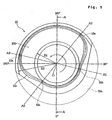
- Fig. 1 is a vertical section of a sealing apparatus according to a first embodiment of the present invention as taken along line I - I of Fig. 3
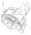
- Fig. 2 is a perspective view for explaining a rotating portion of the sealing apparatus
- Fig. 3 is an explanatory illustration showing operating condition of the sealing apparatus
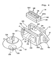
- Fig. 4 is an exploded perspective view showing a structure of a rocking support member
- Fig. 5 is a front elevation showing a shape of a cam member on the side of a stationary portion
- Fig. 6 is a side elevation showing a condition where an anvil (second clamping member) is moved at a retracted position away from a horn (first clamping member)
- Fig. 1 is a vertical section of a sealing apparatus according to a first embodiment of the present invention as taken along line I - I of Fig. 3
- Fig. 2 is a perspective view for explaining a rotating portion of the sealing apparatus
- Fig. 3 is an explanatory illustration showing operating condition of the sealing apparatus
- FIG. 7A is a side elevation showing a condition where the rocking support member is pivoted to contact the anvil to the horn
- Fig. 7B is a side elevation showing a condition where the anvil is urged onto the horn under pressure with compressing an elastic member.
- a bearing portion 3 is provided on a stationary table 4 as stationary portion.
- a rotary shaft 3a is rotatably supported by ball bearings 3b held in the bearing portion 3.
- a rotation center axis of the rotary shaft 3a is shown by O - O.
- a timing wheel 2 having teeth on the circumference is fixed.
- a cogged belt is wrapped around. The cogged belt is driven by a driving force from a driving source having a not shown motor for applying the driving force to the timing wheel 2.
- rotating driving means is formed from the driving source, the cogged belt and the timing wheel 2.
- a rotary base 6 to be a rotating portion is rigidly secured on the rotary shaft 3a.
- a rotary drum 5 is secured on the rotary base 6, a rotary drum 5 is secured.
- the rotary base 6 is placed in opposition with the stationary table 4 in parallel relationship.
- a plurality of rectangular windows 5a elongated in the direction parallel to the rotation center axis O - O are formed on the outer peripheral face 5A of the rotary drum 5.
- the rectangular windows 5a are arranged at an equal pitch in circumferential direction.
- the windows 5a are arranged in six angular positions 60° apart from each other with respect to the rotation center axis O - O.
- the rotating portion is provided with a sealing mechanism.
- This sealing mechanism has first and second clamping members for clamping and sealing a continuous soft work therebetween.
- the sealing mechanism is an ultrasonic sealing mechanism, of which the first clamping member is a horn 8 and the second clamping member is an anvil 14.
- the horns 8 and the anvils 14 are both provided on the rotating portion for rotation together with the rotary base 6 and the rotary drum 5.
- the horns 8 are secured on the rotary base 6 within the rotary drum 5.
- the horns 8 and ultrasonic generating means 7 connected to the horns are arranged radially about the rotation center axis O - O.
- the angular positions of the horns 8 and the ultrasonic generating means 7 match the angular positions of the windows 5a.
- Respective horns 8 are externally projected through the windows 5a of the rotary drum 5 to have seal opposing surfaces 8a at the leading ends thereof.
- the seal opposing surfaces 8a of the horns 8 are oriented outwardly in normal direction (radial direction) about the rotation center axis O - O and located parallel to the rotation center axis O - O. Projecting height of each of the seal opposing surfaces 8a from the outer peripheral face of the rotary drum 5 is h.
- the rotary base 6 is of hexagonal shape.
- Rocking support members 9 are provided on the outer periphery portion of the rotary base 6.
- Each rocking support member 9 is constructed to include a rocking portion 10 and a holding portion 11.
- the rocking portion 10 and the holding portion 11 are fixed with each other.
- the rocking portion 10 is formed into substantially fan shaped configuration.
- a rocking shaft 10A provided at the center of curvature of the fan shape, the rocking portion 10 is pivotably supported with respect to the outer periphery portion of the rotary base 6.
- the rocking shaft 10A is oriented perpendicular to the rotation center axis O - O.
- the rocking support member 9 is pivotable about the rocking shaft 10A between clamping position and retracted position.
- a cam member 15 is rigidly secured on the surface of the stationary table 4 in opposition to the rotary base 6. As shown in Fig. 5 , when viewed from the front side, the cam member 15 is of partly cut-out disc shape. The cut-out portion is indicated at 15a.
- the center of the cam member 15 matches with the rotation center axis O -O of the rotating portion.
- a groove portion 15b is formed between an inner radius R1 and an outer radius R2 about the rotation center axis O - O.
- a cross-sectional shape of the groove portion 15b is arc-shape of radius r1 about a pivoting center of the rocking portion 10 (center of the rocking shaft 10A).
- a concave surface of the groove portion 15b is of doughnut shape extending entire circumference about the rotation center axis O - O.
- the outer periphery side of the groove portion 15b is cut out.
- a cam groove 15c to be a cam profile is formed on the concave surface of the groove portion 15b.
- the cam groove 15c is recessed in a direction perpendicular to a tangential line L - L of the curve of the concave surface of the groove portion 15b (oriented in radial direction with respect to the axial center of the rocking shaft 10A).
- a follower 10a is provided on the circumferential edge of the rocking portion 10.
- the follower 10a is a rotatable roller. In the alternative, the follower 10a may be a non-rotatable projection.
- the cam groove 15c extends along an arc of constant radius about the rotation center axis O - O at a position the most distant from the rotation center axis O - O within an angular range between angular positions A2 and A3, and also extends along an arc of constant radius about the rotation center axis O - O at a position the closest to the rotation center axis O - O within an angular range between angular positions A0 to A1.
- Fig. 4 shows the holding portion 11 as viewed from the side opposed to the rotary drum 5.
- an elastic member 13 is mounted within the holding portion 11.
- the anvil 14 as the second clamping member of the sealing mechanism is supported.
- the holding portion 11 comprises: a rear side portion having a fixing surface 11A, on which the rocking portion 10 is secured; a bottom side portion having a mounting surface 11B, on which the elastic member 13 is secured; and two frame portions 11a and 11a on left and right sides thereof.
- openings 11C and 11C are formed on the left and right sides, and an opening 11D is formed between the two frame portions 11a and 11a to be opposed to the rotary drum 5.
- the rocking portion 10 has a supporting hole 10A1 to receive the rocking shaft 10A for pivotably supporting the rocking portion 10.
- the elastic member 13 has: a flexibly and elastically deformable bag shaped body (casing); a disc-shaped supporting plate 13A mounted on the top of the bag shaped body; and a disc-shaped fixing plate 13B mounted on the bottom of the bag shaped body.
- the bag body of the elastic member 13 is made of an elastically deformable material, such as rubber, or a composite material, such as rubber combined with reinforcing member.
- the bag body By supplying an air as working fluid into a hollow portion of the bag body, the bag body functions as air damper or air spring.
- the internal pressure of the bag body is set at a predetermined value by the supplied air pressure.
- Both the supporting plate 13A and the fixing plate 13B are provided with vertically extending tap holes 13a.
- the fixing plate 13B is further provided with a nozzle 13b, to which an air pipe is connected.
- the internal pressure of the elastic member 13 can be set by air pressure introduced through the air pipe and the nozzle 13b.
- Means for setting internal pressure of the elastic member 13 has a construction comparable with that discussed later with respect to another embodiment with reference to Fig. 14 . Specifically, the air pressure to be supplied to each of the elastic members 13 provided in a plurality of sealing mechanisms can be set independently of the other.
- the elastic member 13 is installed in the holding portion 11 in such a state that its radially expanded portions protrude outwardly through the openings 11C and 11C.
- the tap holes 13a and 13a formed in the fixing plate 13B are placed in alignment with mounting holes 11b and 11b formed in the mounting surface 11B of the holding portion 11 for receiving not shown fastening bolts which are inserted and tightened from outside of the holding portion 11.
- the elastic member 13 is fixed in the holding portion 11.
- a diameter d of the supporting plate 13A of the elastic member 13 is set to be greater than a width dimension W of the opening 11D.
- the inner surfaces 11c and 11c of the frame portions 11a and 11a are not parallel to the mounting surface 11B but are tilted at an angle ⁇ such that the inner surfaces 11c and 11c go away from the mounting surface 11B as they go away from the rocking portion 10.
- the fixing surface 11A on which the rocking portion 10 is fixed is at 90° with respect to the mounting surface 11B.
- the surface of the supporting plate 13A is not in parallel relationship with the mounting surface 11B but tilted at the tilting angle ⁇ to increase distance to the mounting surface 11B as increasing distance from the rocking portion 10.
- the anvil 14 has a base 14A with a uniform thickness over its entire length, and a pair of ridge portions 14B and 14B formed on the surface of the base 14A to extend in the longitudinal direction in parallel relationship with each other.
- Surfaces of the ridge portions 14B and 14B serve as seal opposing surfaces 14a and 14a to be opposed to the horn 8.
- the seal opposing surfaces 14a and 14a serve as pattering surfaces for defining a pattern of sealed portions to be formed in the continuous soft work.
- the base 14A of the anvil 14 is provided at its longitudinally opposed two ends with through holes 14A1 and 14A1, and mounted on a support base 14C by means of not shown bolts. Furthermore, the support base 14C has not shown through holes formed at two positions. By fastening with not shown bolts inserted into the tap holes 13a and 13a and into the through holes formed in the support base 14C, the base 14A and the support base 14C are firmly secured on the surface of the supporting plate 13A.
- the support base 14C of the anvil 14 and the seal opposing surfaces 14a are parallel with each other. Therefore, in the condition where the anvil 14 is fixed on the supporting plate 13A of the elastic member 13 within the holding portion 11, the seal opposing surfaces 14a are tilted at the tilting angle ⁇ to increase distance to the mounting surface 11B as increasing distance from the rocking portion 10 (rocking shaft 10A).
- Fig. 9 is a section taken along line IX - IX of Fig. 8B and showing a condition where the sealed portion is formed
- Fig. 10 is a section taken along line X - X of Figs. 8B and 9 .
- Fig. 8B shows the continuous soft work 30 in which sealed portions S has been formed with the horns 8 and the anvils 14 of the sealing apparatus 1. After forming the sealed portions S in the continuous soft work 30, the continuous soft work 30 is cut along cutting lines C1 - C1 between adjacent sealed portions S to manufacture the pants type disposable diapers as soft absorbent articles. On the other hand, Fig. 8A show the continuous soft work 30 in developed condition.
- a first sheet 32 is positioned at the back, and a second sheet 31 is stacked on the first sheet 32.
- the first sheet 32 has a larger width dimension than that of the second sheet 31.
- the first sheet 32 is folded back to have its side edge 32a over the second sheet 31.
- the first sheet 32 is folded back to have its side edge 32b over the second sheet 31.
- Such folded condition is shown in Fig. 10 .
- a plurality of waist bands 35 are disposed between the first sheet 32 and the second sheet 31.
- a plurality of waist bands 36 are disposed between the first sheet 32 and the second sheet 31.
- the plurality of waist bands 35 and 36 are arranged in parallel relationship and extend straight in feeding direction of the strip form body.
- leg bands 37 and 38 are provided between the first sheet 32 and the second sheet 31 .
- leg bands 37 and 38 are curved into waveform and extend in feeding direction of the strip form body, respectively.
- leg holes 34 are formed in regions surrounded by the leg bands 37 and 38, which will serve as leg inserting portions of pants
- the waist bands 35 and 36 and the leg bands 37 and 38 are sandwiched between the first sheet 32 and the second sheet 31 in a condition elongated in feeding direction of the strip form body by a predetermined degree of elongation. Then, the first sheet 32, the second sheet 31, and the waist bands 35 and 36 and the leg bands 37 and 28 sandwiched therebetween are bonded with each other by hot-melt type adhesive or the like.
- the first sheet 32 and the second sheet 31 has air permeability and liquid blocking ability and are heat-fusible.
- the first sheet 32 and the second sheet 31 may be spunbonded or meltblown non-woven fabric formed from thermoplastic synthetic fibers, or a laminated sheet of the foregoing non-woven fabrics.
- one of the first sheet 32 and the second sheet 31 may be the non-woven fabric and the other may be air permeable plastic film.
- the waist bands 35 and 36 and the leg bands 37 and 38 are formed from elastically extensible member, such as string form or band form rubber or synthetic rubber.
- liquid absorptive bodies 33 are provided between adjacent leg holes 34.
- the liquid absorptive bodies 33 are of hourglass shape or rectangular shape and are arranged with a given interval along feeding direction of the strip form body.
- the liquid absorptive body may be formed by wrapping crushed pulp, mixture of crushed pulp and superabsorbent polymer (SAP), a laminate of hydrophilic non-woven fabrics, air-laid pulp, or the like, in a liquid permeable top sheet. Then, the respective liquid absorptive bodies 33 are bonded on the surface of the second sheet 31 by hot-melt type adhesive or the like.
- the top sheet may be formed from spunlaced non-woven fabric, through-air bonded non-woven fabric, plastic film having apertures for liquid passage, or the like.
- the continuous soft work 30 shown in Fig. 8B is formed by folding the strip form body shown in Fig. 8A along a longitudinally extending center line O1 - O1 into two ply sheet.
- the soft work 30 in which the first sheet 32 and the second sheet 31 are stacked is clamped between the horn 8 and the anvil 14 at a position between adjacent liquid absorptive bodies 33 for ultrasonic sealing.
- the soft work 30 to be clamped between the horn 8 and the anvil 14 has the smallest thickness in the intermediate portion where four sheets (two first sheets 32 and two second sheets 31) are stacked.
- the soft work 30 has the largest thickness in the portion to be the waist side of pants where the folded-back portions of the first sheet 32 having the side edges 32a and 32b are further stacked in addition to the four sheets and the waist bands 35 and 36 are disposed therein.
- the leg bands 37 and 38 are disposed in stacked four sheets. Therefore, the thickness of the leg side is greater than that of the intermediate portion and smaller than that of the waist side.
- first sheet 32 and the second sheet 31 are formed from a heat-fusible material, they generate an internal heat due to vibration applied from the horn. Thus, the first sheet 32 and the second sheet 31 are welded depending upon fine projection pattern formed on the seal opposing surfaces 14a of the anvil 14 to form the sealed portion S.
- a pattern of the sealed portion S formed by the fine projection pattern is such that thin seal lines are repeated in a row.
- the continuous soft work 30 is cut along the cutting lines C1 - C1 between adjacent sealed portions S to complete pants type disposable diapers as soft absorbent articles.
- the soft absorbent article manufactured by the sealing apparatus according to the present invention may be sanitary napkin, panty liner and so forth.
- the continuous soft work 30 is wound on a supply roll 21 provided at a supply portion (i) and supplied to an outer peripheral face 5A of the rotary drum 5.
- the continuous soft work 30 is wrapped on the outer peripheral face 5A of the rotary drum 5 (in further detail on the seal opposing surfaces 8a of the horns 8 projecting from the outer peripheral face 5A) over an angle of about 180°, and is released from the rotary drum 5 at an eject portion (ii) to be externally withdrawn by wrapping on an eject roll 22.
- the continuous soft work 30 is continuously fed to the supply portion (i) at a constant speed.
- a rotary driving force is transmitted to the timing wheel 2 to rotate the rotary shaft 3a, the rotary base 6 as rotating portion and the rotary drum 5 in counterclockwise direction in Figs. 2 and 3 at a constant angular velocity.
- the continuous soft work 30 contact with the seal opposing surfaces 8a of the horns 8 projecting from the outer peripheral face 5A of the rotary drum 5 thus rotating. Therefore, in the shown embodiment, the angular velocity of the rotating portion is set so that the rotational peripheral speed of the seal opposing surfaces 8a matches with the supply speed of the continuous soft work 30. Accordingly, on the outer peripheral face 5A of the rotary drum 5, the seal opposing surfaces 8a of the horns 8 and the continuous soft work 30 rotate together without causing any slippage with respect to each other.
- the circumferential arrangement pitch of the horns 8 projecting from the outer peripheral face 5A of the rotary drum 5 matches with the arrangement pitch of the liquid absorptive bodies 33 and the arrangement pitch of the leg holes 34 of the continuous soft work 30 shown in Fig. 8B . Therefore, when the continuous soft work 30 is supplied to the outer peripheral face 5A of the rotary drum 5, the liquid absorptive body 33 is located between adjacent horns 8 (between adjacent sealing mechanisms) as shown in Fig. 9 , so that the seal opposing surface 8a of the horn 8 confronts the portion where the liquid absorptive body 33 is not present.
- rocking support member 9 is pivoted within the cut-out portion 15a of the cam member 15. Therefore, the rocking support member 9 can be pivoted up to the position where the seal opposing surface 14a of the anvil 14 is placed at 90° with respect to the rotation center axis O - O.
- the supply portion (i) and the eject portion (ii) for supplying and ejecting the continuous soft work 30 are located between the angular position A0 and the angular position A1. Between these angular positions, the anvil 14 is pivoted to the retracted position so as not to interfere with the continuous soft work 30, away from the path of the continuous soft work 30 to be supplied to the rotary drum 5 and the path of the continuous soft work 30 ejected from the rotary drum 5. Accordingly, supplying and ejecting of the continuous soft work 30 will never be interfered by the anvil 14.
- the follower 10a is moved from the angular position A3 to the angular position A0, the follower 10a is guided by the cam groove 15c toward the rotation center axis O - O, so that the anvil 14 is pivoted away from the horn 8 and the continuous soft work 30. Then, when the follower 10a reaches the angular position A0, the anvil 14 is pivoted to the retracted position angled at about 90° with respect to the rotation center axis O - O, as shown in Fig. 6 .
- each rocking support member 9 While the follower 10a of each rocking support member 9 is moved from the angular position A2 to the angular position A3, electric power is supplied to the ultrasonic generating means 7 for a predetermined period to drive the horn 8 to vibrate for the predetermined period for forming the sealed portions S in the continuous soft work 30, as shown in Fig. 8B .
- the soft work 30 is fusion-bonded.
- the continuous soft work 30 after completion of seal as shown in Fig. 8B is ejected by the eject roll 22.
- the continuous soft work 30 ejected by the eject roll 22 is cut along the cutting line C1 - C1 shown in Fig. 8B between adjacent sealed portions S to product individual pants type diapers.
- Fig. 6 shows a condition where the rocking support member 9 is pivoted to the retracted position.
- the seal opposing surface 8a at the leading end of the horn 8 matches with a plane Lh parallel to the rotation center axis O - O and to the outer peripheral face 5A of the rotary drum 5.
- the rocking center of the rocking support member 9 (center of the rocking shaft 10A) is located on the plane Lh.
- a plane extending across the rocking center and perpendicular to the plane Lh is indicated at Lv.
- the mounting surface 11B of the holding portion 11 of the rocking support member 9 is parallel to the plane Lv.
- Air supply to the elastic member 13 via the nozzle 13b is controlled to provide a predetermined internal pressure.
- the supporting plate 13A of the elastic member 13 is urged onto the tilted inner surfaces 11c of the frame portions 11a of the holding portion 11 by the internal pressure of the elastic member 13. Therefore, the seal opposing surface 14a of the anvil 14 is tilted at the tilting angle ⁇ with respect to the plane Lv to increase projecting amount from the plane Lv as increasing distance from the rocking shaft 10A.
- the seal opposing surface 14a of the anvil 14 is tilted toward contacting direction with the horn 8 as increasing distance from the rocking center. Therefore, as shown in Fig. 7A , when the rocking support member 9 is pivoted over an angle (90° - ⁇ ) from the condition of Fig. 6 , the seal opposing surface 14a of the anvil 14 is placed substantially parallel to the seal opposing surface 8a of the horn 8.
- the surface of the supporting plate 13A of the elastic member 13 is placed away from the inner surfaces 11c of the frame portions 11a of the holding portion 11. Then, the mounting surface 11B, the supporting plate 13A and the seal opposing surface 14a are placed in parallel or substantially parallel relationship with each other.
- the anvil 14 is subject to elastic force of the elastic member 13 to be elastically pressed toward the horn 8.
- the continuous soft work 30 is the continuous body of the pants type disposable diapers
- the continuous soft work 30 is not flat in the portion where the sealed portion S is to be formed with the horn 8 and the anvil 14, as shown in Fig. 10 .
- the thickness is the largest in the waist side, decreased in the intermediate portion, and then increased in the leg side. Accordingly, the soft work 30 to be sealed is locally different in thickness and has unevenness on the surface.
- the portion forming the sealed portion S does not have uniform thickness and varies in thickness over different portions thereof, because the anvil 14 is urged toward the horn 8 by an air dumper i.e., the bag shaped elastic body filled with air (fluid), the seal opposing surface 14a of the anvil 14 can flexibly follow to variation of the thickness of the continuous soft work 30. Furthermore, by the internal pressure of the elastic body 13, the continuous soft work 30 can be substantially uniformly depressed at respective portions of the sealed portion S by the horn 8 and the anvil 14. Thus, seal quality of the sealed portion S can be made uniform.
- the internal pressure inside of the bag body of the elastic member 13 can be controlled by supply of air pressure through the nozzle 13b. Therefore, control for varying the internal pressure inside of the bag body of the elastic member 13 is facilitated depending upon the material and structure of the continuous soft work 30 to be sealed. Accordingly, even when the structure of the continuous soft work 30 is varied and associating therewith, the seal pattern on the seal opposing surface 14a of the anvil 14 is varied, preparation can be completed merely by changing the internal pressure of the elastic member 13 to permit sealing operation under optimal condition, constantly.
- sealing condition can be constantly maintained at any production speed by setting power supply period to the ultrasonic generating means 7 at a given period and by setting the sealing pressure at a predetermined magnitude.
- various production speeds can be realized.
- the ultrasonic generating means 7 in movable manner along normal direction (radial direction) with respect to the rotary drum 5 so that the projection height h of the leading end of the horn 8 from the outer peripheral face 5A of the rotary drum 5 can be varied.
- the projection height h can be varied depending upon the thickness of the liquid absorptive body 33 of the soft work 30 to certainly seal the sheets for any product provided with the liquid absorptive body.
- the projection height h shown in Fig. 9 is preferably one half of the thickness T of the continuous soft work 30at the portion where the liquid absorptive body 33 is provided. Namely, it is preferred that the projection height h is substantially equal to the thickness of the liquid absorptive body 33 in developed condition.
- the sheets 31 and 32 can be certainly clamped by the horn 8 and the anvil 14 without being influenced by the thickness of the liquid absorptive body 33.
- the horn 8 is fixed on the side of the rotation center axis O - O and the anvil 14 is provided rockably outwardly of the horn 8.
- the sealing mechanism may be a heat sealing mechanism for establishing seal by heating a first clamping member and a second clamping member and clamping the continuous soft work with these first and second clamping members.
- the rocking driving means is formed from the follower 10a projecting from the rocking support member 9 and the cam groove 15c formed in the cam member 15.
- a projecting cam follower is formed in the cam member and a recess or groove to be guided along the projecting cam follower is formed in the rocking support member.
- rocking driving means for driving the rocking support member 9 a cylinder mechanism or the like or a link mechanism which will be discussed later in discussion for the second embodiment may also be employed.
- the elastic member 13 for biasing the anvil may be a coil spring or the like in place of the elastic member discussed above.
- Figs. 11 to 14 show a sealing apparatus 40 according to a second embodiment of the present invention.
- Fig. 11 is a vertical section of the sealing apparatus 40
- Fig. 12 is a front elevation showing a structure of a cam member
- Fig. 13 is a side elevation showing a supporting condition of the anvil 14
- Fig. 14 is an illustration showing a construction of a piping for setting internal pressure of elastic members.
- the sealing apparatus 40 shown in Fig. 11 is different from the sealing apparatus 1 of the first embodiment only in constructions of the rocking driving means and the ultrasonic generating means, number of the elastic members supporting each anvil 14, and an internal pressure setting condition for respective elastic members. Other constructions are substantially the same as the first embodiment.
- the soft work 30 to be continuously supplied is similar to that shown in Figs. 8A, 8B to 10 .
- Seal timings A0, A1, A2 and A3 of the sealing mechanism are the same as those of the sealing apparatus 1.
- the position of the rotation center of the rocking support member, the tilting angle ⁇ of the anvil 14 when the rocking support member is pivoted to the retracted position, relative motion of the anvil 14 and the horn 8 when the anvil 14 is pivoted to abut on the horn 8, the optimal value of the projecting height h of the horn 8 from the rotary drum 5 and so forth are the same as the sealing apparatus 1.
- the sealing mechanism in the sealing apparatus 40 shown in Figs. 11 and 12 is an ultrasonic sealing apparatus comprising the horn 8 as the first clamping member and the anvil 14 as the second clamping member.
- the horn 8 is driven by a plurality of ultrasonic generating means 7 to vibrate.
- two ultrasonic generating means 7A and 7B are provided in each of sealing mechanisms radially arranged in the rotary drum 5.
- Two ultrasonic generating devices 7A and 7B are arranged along the width direction of the rotary drum 5, namely the direction of the rotation center axis O - O of the rotary drum 5.
- the thickness of the stacked body is large in the waist side and the leg side. Accordingly, by arranging two ultrasonic generating devices 7A and 7B along the rotation center axis O - O, ultrasonic vibration can effectively act on the thick portions of the soft work 30 for uniformly fusion-bonding overall seal region of the soft work 30.
- each sealing mechanism ultrasonic vibration is applied to the common horn 8 by two ultrasonic generating means 7A and 7B in the shown embodiment.
- two ultrasonic generating means 7A and 7B it is also possible to provide two horns and to support respective horns by respective ultrasonic generating means 7A and 7B.
- the rotary drum 5 is fixed on the rotary base 6 of equilateral hexagonal front elevation as shown in Fig. 12 .
- the rocking support member 50 is supported. Accordingly, the rocking support members 50 are spaced 60° from each other.
- the rocking support member 50 is constructed to include a rocking portion 51 and a holding portion 52.
- the rocking portion 51 and the holding portion 52 are fixed with each other.
- Each rocking portion 51 is rockably supported on the edge of the rotary base 6 by a rocking shaft 51A. It should be noted that the rocking shaft 51A is oriented perpendicular to the rotation center axis O - O.
- the cam member 60 On the surface of the stationary table 4 opposing to the rotary base 6, a cam member 60 forming the rocking driving means is secured.
- the cam member 60 is of flat plate shape having a predetermined thickness, and is formed with a cam groove 61 to be a cam profile on the front surface.
- the cam groove 61 is continuous around the rotation center axis O - O.
- a depth direction of recessed portion of the cam groove 61 is oriented in parallel to the rotation center axis O - O.
- a link mechanism is provided between the rocking portion 51 and the cam member 60.
- a drive link 53 is pivotably supported on the rocking portion 51 through a connection shaft 51B provided in an orientation perpendicular to the rotation center axis O - O.
- a base portion 54A of a pivotal link 54 is pivotably supported by a support shaft 54a.
- the axial direction of the support shaft 54a is parallel to the rotation center axis O - O.
- the leading end of the drive link 53 is pivotably connected to the leading end portion of an arm portion 54B of the pivotal link 54 through a connection shaft 55.
- the axial direction of the connection shaft 55 is parallel to the rotation center axis O - O.
- the driving member 56 On the pivotal link 54, the driving member 56 is mounted.
- the driving member 56 includes a driving support body 56a fixed at the intermediate portion of the pivotal link 54 in non-pivotable fashion, and a follower 56b provided on the driving support body 56a.
- the follower 56b is movable along the cam groove 61.
- the follower 56a may roll or slide without rolling along the cam groove 61.
- Fig. 12 the driving support body 56a is eliminated for the purpose of illustration, showing relative position between the pivotal link 54, the follower 56b and the drive link 53.
- the rocking driving means is formed from the cam member 60 and the follower 56b.
- the rocking support member 50 is pivoted by the cam groove 61. Pivoting timing of the rocking support member 50 is the same as the sealing apparatus 1 of the first embodiment.
- the rocking support member 50 is pivoted about the rocking shaft 51A toward the outer peripheral face 5A of the rotary drum 5 to reach the clamping position.
- the rocking support member 50 is pivoted about the rocking shaft 51A toward the stationary table 4 over about 90° to be placed at the retracted position.
- two elastic members 71 and 72 are provided in each holding portion 52.
- Two elastic members 71 and 72 are arranged along the width direction of the rotary drum 5, namely along the rotation center axis O - O.
- each of the elastic members 71 and 72 is similar to the elastic member 13 shown in Fig. 4 . That is, each of the elastic members 71 and 72 comprises an elastically deformable bag body, in which air as fluid is supplied.
- the basic construction of the holding portion 52 is the same as the holding portion 11 shown in Fig. 4 .
- Two elastic members 71 and 72 are fixed on a mounting surface 52B of the holding portion 52 via fixing plates 71A and 71B.
- the holding portion 52 also has frame portions 51a and 51a similar to the frame portions 11a and 11a of Fig. 4 .
- the frame portions 51a and 51a has inner surfaces 51c and 51c, which are tilted at the angle ⁇ with respect to the plane parallel to the mounting surface 52B to approach toward the horn 8 as increasing distance from the rocking shaft 51A.
- a supporting plate 70 is secured on the other ends of the elastic members 71 and 72.
- the anvil 14 is secured on the supporting plate 70.
- the supporting plate 70 is urged onto the inner surfaces 51c and 51c by fluid pressure within the elastic members 71 and 72.
- the surface of the anvil 14 has the tilting angle ⁇ . Effect of providing the tilting angle ⁇ is the same as the sealing apparatus 1 of the first embodiment.
- nozzles 73 and 74 are provided on the fixing plates 71A and 71B. To these nozzles 73 and 74, air pipes 75 and 76 are connected. Through the air pipes 75 and 76 and the nozzles 73 and 74, the internal pressures in the elastic members 71 and 72 can be set individually.
- the thickness in the waist side is greater than the thickness in the leg side. Accordingly, in the shown embodiment, the internal pressure of the elastic member 72 urging the anvil 14 at the leg side is set to be slightly higher than the internal pressure of the elastic member 71 urging the anvil at the waist side.
- the anvil 14 is urged onto the horn 8 with relatively large pressure on the leg side, and the anvil 14 is urged onto the horn 8 with relatively small pressure on the waist side.
- the soft work 30 having different thicknesses can be substantially uniformly fusion-bonded over entire length from the waist side to the leg side.
- local excessive fusing can be avoided which might otherwise cause locally stiffening of the sealed portion S to degrade texture in final absorbent articles.
- the anvil 14 is single. However, it is possible to separately provide two anvils: one to be biased by the elastic member 71; and the other to be biased by the elastic member 72. It is also possible to provide a single anvil having a thin portion formed between a portion supported by the elastic member 71 and a portion supported by the elastic member 72 for permitting independent behavior of the portion to be biased by the elastic member 71 and the portion to be biased by the elastic member 72.
- Fig. 14 shows a piping to be pressure setting means, which can variably set the internal pressure of respective of the elastic members 71 and 72 respectively provided in each sealing mechanism.
- a high pressure air is applied to two pressure setting portions 81 and 82 from an air pressure generating portion 80, such as air pump or the like.
- One pressure setting portion 81 is adapted to set supply pressure to the elastic members 71 and 72 at a predetermined value when sealing operation is performed for the soft work 30.
- the other pressure setting portion 82 is for discharging air from the elastic members 71 and 72 for releasing the pressure to the supporting plate 70 by the elastic members 71 and 72.
- This pressure setting portion 82 is used in set-up operations such as supplying of the soft work 30 to the sealing apparatus 40 and rotating of the rotary drum 5 for a predetermined period upon initiation of sealing operation, for example.
- the pressure setting portions 81 and 82 may be constructed as regulators employing diaphragms.
- the pressure setting portions 81 and 82 are switched by a switching valve 84. Forward of the switching valve 84, there is provided a pressure sensor 85.
- the pressure sensor 85 is designed to generate an electric signal 85a when the pressure within the piping is lowered across a predetermined value. When the electric signal 85a is generated, sealing operation by the sealing apparatus 40 is interrupted.
- a pressure reducing pressure control valve 86 communicated with inside of the elastic member 71 through a pipe 75 and a pressure reducing pressure control valve 87 communicated with inside of the elastic member 72 through a pipe 76 are provided.
- the pressure set by the pressure setting portion 81 is reduced by the pressure reducing pressure control valve 86 to be supplied to the elastic member 71 and is reduced by the pressure reducing pressure control valve 87 to be supplied to the elastic member 72.
- the pressure reducing pressure control valves 86 and 87 can individually set pressures to be supplied to the elastic members 71 and 72 by adjusting an amount of valve opening.
- the internal pressure of the elastic member 71 is set slightly low and the internal pressure of the elastic member 72 is set slightly high, for example.
- one pressure reducing pressure control valve being for simultaneously adjusting all of air pressures to be supplied to the plurality of elastic members 71; and the other pressure reducing pressure control valve being for simultaneously adjusting all of air pressures to be supplied to the plurality of elastic members 72.
- the pressure sensor 85 and the pressure reducing pressure control valves 86 and 87 are mounted on the rotary base 6, and piping connecting the switching valve 84 and the pressure sensor 85 is arranged along the rotation center axis O - O, and is extended externally from the sealing apparatus 40 via a rotary joint.
- the construction in which a single elastic member 13 is provided in each holding portion 11, has been disclosed.
- the construction in which two elastic members 71 and 72 are provided in each holding portion 52, has been disclosed.
- the present invention is not limited to these embodiments, and three or more elastic members may be provided for each holding portion.
- advantages of the present invention may include one or more of the following:
- the second clamping member is pivoted by the use of a cam member, as in the foregoing embodiments, rotating force of a rotating portion can be used for driving the second clamping member in clamping and unclamping directions. Therefore, the driving power source can be minimized.
Landscapes
- Engineering & Computer Science (AREA)
- Mechanical Engineering (AREA)
- Health & Medical Sciences (AREA)
- Physics & Mathematics (AREA)
- Textile Engineering (AREA)
- General Health & Medical Sciences (AREA)
- Veterinary Medicine (AREA)
- Vascular Medicine (AREA)
- Life Sciences & Earth Sciences (AREA)
- Animal Behavior & Ethology (AREA)
- Biomedical Technology (AREA)
- Public Health (AREA)
- Heart & Thoracic Surgery (AREA)
- Epidemiology (AREA)
- Manufacturing & Machinery (AREA)
- Fluid Mechanics (AREA)
- Thermal Sciences (AREA)
- Absorbent Articles And Supports Therefor (AREA)
- Lining Or Joining Of Plastics Or The Like (AREA)
- Package Closures (AREA)
Abstract
Description
- The present invention relates generally to a sealing apparatus for forming sealed portion in a continuous soft work for forming soft article, such as disposable diaper, sanitary napkin and so forth, and a manufacturing process of such soft article having sealed portion. More particularly, the invention relates to a sealing apparatus and a manufacturing process, which can certainly perform sealing operation with simple operation.
- For example, Japanese Patent Application Laid-Open No.
10-513128 PCT/US96/00618 - In the above-identified publication, an ultrasonic sealing mechanism constituted of a plurality of ultrasonic horns and anvils is provided in a rotary working drum for rotation together with the rotary working drum. The web is wrapped around the outer peripheral face of the rotary working drum to be fed from upstream side and downstream side by rotation of the rotary working drum. The ultrasonic horn is driven by a cam for reciprocation in width direction on the outer peripheral face of the rotary working drum. Within the rotary working drum, the anvils are provided in opposition to the ultrasonic horns. Then, while the continuous web is fed by rotation of the rotary working drum, the ultrasonic horn is moved transversely in the width direction on the web for a given distance for forming line form ultrasonic sealed portions in the web.
- However, in the sealing apparatus disclosed in Japanese Patent Application Laid-Open No.
10-513128 - On the other hand, upon continuously sealing absorbent article, such as diaper, it is typical that rubber or gather provided in the web is to be subject to the ultrasonic seal together with the web. In case of the product having the rubber or gather, undulation is formed in the web. When sealing operation for such web is performed by means of the sealing apparatus disclosed in Japanese Patent Application Laid-Open No.
10-513128 - Furthermore, it requires complicate control of an air cylinder so as to control the air cylinder to apply a pressurizing force to the ultrasonic horn when the ultrasonic horn comes into contact with the web, and to control the air cylinder to release the pressurizing force on the ultrasonic horn when the ultrasonic horn is moved away from the web.
- Also, upon sealing the web for producing the absorbent article, the thickness of the web tends to be different in the portions to be sealed. In this case, when the ultrasonic horn and the anvil are pressurized by a single pressurizing means, the portion of the web having larger thickness is given greater pressurizing force than that given to the portion of the web having smaller thickness so that welding is dominantly progressed in the larger thickness portion in comparison with the smaller thickness portion. Therefore, the web in the larger thickness portion becomes stiff to differentiate sealing strength and taste of finishing in the sealed portion.
- The present invention has been worked out in view of the foregoing shortcomings in the prior art. It is therefore an object of the present invention to provide a sealing apparatus and a manufacturing process of soft article having sealed portion superior in manufacturing ability in simple construction and achieving uniform seal.
- Another object of the present invention is to provide a sealing apparatus and a manufacturing process of soft article having sealed portion, which can uniformly weld a portion to be sealed in a soft work having locally different thicknesses and prevent occurrence of portions having difference in the sealing strength and taste of finishing.
- According to a first aspect of the present invention, there is provided a sealing apparatus for forming sealed portions in a soft work continuously fed thereto, the sealing apparatus comprising: a rotating portion; rotating driving means for driving the rotating portion to rotate; and a plurality of sealing mechanisms arranged along a rotating direction of the rotating portion to move along with the rotating portion, each sealing mechanism including a first clamping member and a second clamping member for clamping the soft work therebetween within a predetermined angular range with respect to a rotation center of the rotating portion for forming the sealed portions in the soft work,
wherein in each sealing mechanism, the first clamping member is located on the side of the rotation center of the rotating portion to orient a seal opposing surface thereof outwardly in a normal direction extending from the rotation center, the second clamping member corresponding to the first clamping member is located outside of the first clamping member in the normal direction, and the second clamping member is pivotably supported on the rotating portion for pivoting between a claming position, in which a seal opposing surface thereof is urged toward the seal opposing surface of the first clamping member, and a retracted position located away from the first clamping member, and
wherein rocking driving means is provided for driving the second clamping member to pivot as the rotating portion rotates so that the second clamping member is located in the clamping position within the predetermined angular range and located in the retracted position within another angular range so as not to interfere with feeding of the soft work into the sealing mechanisms and ejecting of the soft work from the sealing mechanisms. - With the construction of the first aspect of the invention as set forth above, the second clamping member forming the sealing mechanism can be radially pivoted away from the radially arranged first clamping member to be placed in the retracted position. Therefore, the second clamping member can be moved between the clamping position for performing sealing operation and the retracted position not interfering with transportation of the continuous soft work only by simple rocking or pivoting motion. Also, since sealing operation is performed by contacting and releasing the first clamping member and the second clamping member, sealing operation can be performed at high speed.
- For example, the continuous soft work includes at least a sheet which can be fusion-bonded. The continuous soft work may further include liquid absorptive bodies spaced apart from each other in a feeding direction thereof and supported by the sheet, and sealing may be effected in a condition where each liquid absorptive body is located between adjacent sealing mechanisms and the sheet is folded back.
- By positioning the liquid absorptive body between adjacent sealing mechanisms, the sheet can be certainly sealed at the portion where the liquid absorptive body is not present.
- Preferably, the rotating portion includes a rotary drum, and the first clamping member is arranged inside of the rotary drum so that the seal opposing surface of the first clamping member is located at a position projecting from an outer peripheral face of the rotary drum.
- With this construction, the folded sheet can be certainly sealed in the condition where the liquid absorptive body is located between adjacent sealing mechanisms and on the outer peripheral face of the rotary drum.
- Preferably, the seal opposing surface of the second clamping member as pivoted to the retracted position is pivoted over about 90° with respect to a rotation center axis of the rotating portion.
- By pivoting the second clamping member over the foregoing angle to the retracted position, the second clamping member can be certainly retracted to the position not interfering with transportation (feeding and ejecting) of the continuous soft work.
- For example, the rocking driving means is formed from a cam profile fixed at a position opposing to the rotating portion and a follower to move along the cam profile as the rotating portion rotates for pivoting the second clamping member between the clamping position and the retracted position.
- In this case, the cam profile may be defined by a continuous cam groove extending to surround the rotation center of the rotating portion but spaced away from the rotation center.
- For example, the follower is mounted on a rocking support member supporting the second clamping member so that the rocking support member is pivoted between the clamping position and the retracted position by movement of the follower along the cam profile. In an alternative, there may be provided a rocking support member supporting the second clamping member and a link mechanism provided between the rocking support member and the follower so that the rocking support member is pivoted between the clamping position and the retracted position via the link mechanism by movement of the follower along the cam profile.
- As set forth above, by providing fixed cam profile and pivotally driving the second clamping member with taking rotating motion of the rotating portion as driving power source, it becomes unnecessary to provide another driving power source, such as cylinder mechanism or the like, for pivoting the second clamping member per the sealing mechanism.
- In the first aspect of the invention, it is also preferred that the rotating portion includes a rocking support member pivotably supported by a rocking shaft, and the second clamping member is supported on the rocking support member via an elastic member so that when the second clamping member is pivoted to the clamping position, the second clamping member is biased toward the first clamping member by an elastic force developed by the elastic member.
- By biasing the second clamping member toward the first clamping member via the elastic member, uniform pressure can be easily applied to respective portions of the soft work with the seal opposing surface of the second clamping member and the seal opposing surface of the first clamping member even when the soft work has a structure having unevenness.
- According to a second aspect of the present invention, there is provided a sealing apparatus comprising: a sealing mechanism having a first clamping member and a second clamping member for clamping a fusion-bondable soft work therebetween for forming sealed portions in the soft work; and driving means for driving the second clamping member to clamp the soft work between the first clamping member and the second claming member and to move away from the first clamping member,
wherein the second clamping member is supported on a supporting member via an elastic member and the supporting member is driven by the driving means so that the second member is biased toward the first clamping member by an elastic force developed by the elastic member, and the elastic member has a deformable casing into which fluid is introduced. - In the foregoing second aspect of the invention, since the elastic member having the casing (e.g., bag shaped casing) into which fluid is introduced, is employed, the second clamping member can be biased to follow unevenness of the soft work or difference of thickness of the soft work, so that such soft work can be clamped between the first clamping member and the second clamping member as uniformly as possible. As a result, quality of sealed portion can be improved.
- For example, the soft work is continuously fed to the sealing apparatus and a plurality of sealing mechanisms are arranged at intervals along a feeding direction of the continuous soft work so that the sealed portions are formed in the continuous soft work at intervals along the feeding direction by means of the sealing mechanisms.
- Preferably, the sealing apparatus further comprises a rotating portion, and a plurality of sealing mechanisms are arranged at intervals along a rotating direction of the rotating portion and the soft work is continuously fed to the rotating portion so that, as the rotating portion rotates, the sealed portions are formed in sequential order by means of the sealing mechanisms.
- For example, the continuous soft work includes a sheet which can be fusion-bonded and liquid absorptive bodies spaced apart from each other in a feeding direction thereof and supported by the sheet, and sealing is effected in a condition
where each liquid absorptive body is located between adjacent sealing mechanisms and the sheet is folded back. - Here, it is preferred that the sealing apparatus further comprises pressure setting means for varying pressure of fluid within the casing.
- By providing the pressure setting means, the pressure in the casing can be set at an optimal value depending upon kind of the soft work. Therefore, the soft work can be clamped between the second clamping member and the first clamping member under an optimal pressure.
- Preferably, a plurality of elastic members for supporting the second clamping member are provided in the supporting member. In this case, more preferably, the sealing apparatus further comprises pressure setting means for individually setting pressure of fluid within respective casing of the plurality of elastic members.
- By biasing the second clamping member with the plurality of elastic members, the soft work having uneven profile or having portions of different thicknesses can be clamped with a uniform clamping force between the second clamping member and the first clamping member.
- For example, the sealing mechanism is an ultrasonic sealing device, and one of the first clamping member and the second clamping member is a horn and the other is an anvil.
- However, it is, of course, possible to perform heat sealing with the first clamping member and the second clamping member of the sealing mechanism.
- According to a third aspect of the present invention, there is provided a method for manufacturing soft articles respectively having sealed portions, comprising:
- forming sealed portions in a continuous soft work by clamping the soft work between a first clamping member and a second clamping member, the first clamping member and the second clamping member forming a sealing mechanism; and
- cutting the soft work before, simultaneously with or after the forming step,
- In the soft articles, such as disposable diaper, sanitary napkin and so forth produced by the foregoing manufacturing method, material of the soft work, such as sheet and so forth, can be uniformly fusion-bonded in the portion to be sealed, to thereby improve quality of the sealed portion.
- In the third aspect of the invention, for example, a plurality of sealing mechanisms are arranged at intervals along a feeding direction of the continuous soft work so that the sealed portions are formed in the continuous soft work at intervals along the feeding direction by means of the sealing mechanisms. Preferably, a plurality of sealing mechanisms are arranged at intervals along a rotating direction of a rotating portion and the continuous soft work is fed to the rotating portion so that, as the rotating portion rotates, the sealed portions are formed in sequential order by means of the sealing mechanisms.
- For example, with fluid pressure in the casing being set at a predetermined value, optimal sealing condition can be set depending upon structure and/or thickness of the soft work.
- More preferably, a plurality of elastic members are provided and respective elastic members bias the second clamping member. In this case, it is preferred that internal pressures of the plurality of elastic members are set independently.
- By independently setting the internal pressures as set forth above, uniform fusion-bonding quality can be obtained even when the continuous soft work has portions having different thicknesses in a region where the sealed portions are to be formed.
- For example, in case where the continuous soft work has portions having different thickness in a region where the sealed portions are to be formed, it is preferred that internal fluid pressure of the elastic member biasing the second clamping member toward a portion having larger thickness in the soft work and internal fluid pressure of the elastic member biasing the second clamping member toward a portion having smaller thickness in the soft work are set independent of each other.
- Here, the continuous soft work may include a sheet which can be fusion-bonded and liquid absorptive bodies spaced apart from each other in a feeding direction thereof and supported by the sheet, and sealing may be effected at positions between adjacent liquid absorptive bodies in a condition where the sheet is folded back.
- For example, in order to make the quality of the sealed portion uniform, it is preferred that the set pressure of the fluid in the elastic member for applying the biasing force to the portion having smaller thickness is set higher than the set pressure of the fluid in the elastic member for applying the biasing force to the portion having larger thickness.
- In the third aspect of the invention, too, the sealing mechanism may be an ultrasonic sealing device, and one of the first clamping member and the second clamping member may be a horn and the other may be an anvil.
- The present invention will be understood more fully from the detailed description given hereinafter and from the accompanying drawings of the preferred embodiment of the present invention, which, however, should not be taken to be limitative to the invention, but are for explanation and understanding only.
- In the drawings:
-
Fig. 1 is a section of a sealing apparatus according to a first embodiment of the present invention as taken along line I - I ofFig. 3 ; -
Fig. 2 is a perspective view for explaining a rotating portion of the sealing apparatus; -
Fig. 3 is an explanatory illustration showing operating condition of the sealing apparatus; -
Fig. 4 is an exploded perspective view showing a structure of a rocking support member; -
Fig. 5 is a front elevation showing a shape of a cam member on the side of a stationary portion; -
Fig. 6 is a side elevation showing a condition where an anvil is moved at a retracted position away from a horn; -
Fig. 7A is a side elevation showing a condition where the rocking support member is pivoted to contact the anvil to the horn; -
Fig. 7B is a side elevation showing a condition where the anvil is urged to the horn under pressure with compressing an elastic member; -
Fig. 8A is a perspective view showing a developed condition of a continuous soft work; -
Fig. 8B is a perspective view of the continuous soft work in the condition supplied to the sealing apparatus; -
Fig. 9 is a section showing a condition where the continuous soft work is clamped between the horn and the anvil, where the section of the soft work is taken along line IX - IX ofFig. 8B ; -
Fig. 10 is a section showing a condition where the continuous soft work is clamped between the horn and the anvil, where the section of the soft work is taken along line X - X ofFig. 8B ; -
Fig. 11 is a vertical section of a sealing apparatus according to a second embodiment of the present invention; -
Fig. 12 is a front elevation showing a structure of a cam member; -
Fig. 13 is a side elevation of a rocking support portion; and -
Fig. 14 is an explanatory illustration of a piping for supplying air to an elastic member. - The present invention will be discussed hereinafter in detail in terms of the preferred embodiment of the present invention with reference to the accompanying drawings. In the following description, numerous specific details are set forth in order to provide a thorough understanding of the present invention. It will be obvious, however, to those skilled in the art that the present invention may be practiced without these specific details. In other instance, well-known structures are not shown in detail in order to avoid unnecessary obscurity of the present invention.
-
Fig. 1 is a vertical section of a sealing apparatus according to a first embodiment of the present invention as taken along line I - I ofFig. 3 ,Fig. 2 is a perspective view for explaining a rotating portion of the sealing apparatus,Fig. 3 is an explanatory illustration showing operating condition of the sealing apparatus,Fig. 4 is an exploded perspective view showing a structure of a rocking support member,Fig. 5 is a front elevation showing a shape of a cam member on the side of a stationary portion,Fig. 6 is a side elevation showing a condition where an anvil (second clamping member) is moved at a retracted position away from a horn (first clamping member),Fig. 7A is a side elevation showing a condition where the rocking support member is pivoted to contact the anvil to the horn, andFig. 7B is a side elevation showing a condition where the anvil is urged onto the horn under pressure with compressing an elastic member. - In a
sealing apparatus 1 shown inFig. 1 , a bearing portion 3 is provided on a stationary table 4 as stationary portion. Arotary shaft 3a is rotatably supported byball bearings 3b held in the bearing portion 3. InFig. 1 , a rotation center axis of therotary shaft 3a is shown by O - O. On a base end portion of therotary shaft 3a on right side in the drawing, atiming wheel 2 having teeth on the circumference is fixed. On thetiming wheel 2, a cogged belt is wrapped around. The cogged belt is driven by a driving force from a driving source having a not shown motor for applying the driving force to thetiming wheel 2. Then, therotary shaft 3a is continuously driven to rotate at a constant angular velocity in counterclockwise direction in the condition as viewed from left side ofFig. 1 . In the shown embodiment, rotating driving means is formed from the driving source, the cogged belt and thetiming wheel 2. - On the
rotary shaft 3a, arotary base 6 to be a rotating portion is rigidly secured. On therotary base 6, arotary drum 5 is secured. Therotary base 6 is placed in opposition with the stationary table 4 in parallel relationship. - As shown in
Figs. 1 and2 , on the outerperipheral face 5A of therotary drum 5, a plurality ofrectangular windows 5a elongated in the direction parallel to the rotation center axis O - O are formed. Therectangular windows 5a are arranged at an equal pitch in circumferential direction. In the shown embodiment, thewindows 5a are arranged in sixangular positions 60° apart from each other with respect to the rotation center axis O - O. - The rotating portion is provided with a sealing mechanism. This sealing mechanism has first and second clamping members for clamping and sealing a continuous soft work therebetween. In the shown embodiment, the sealing mechanism is an ultrasonic sealing mechanism, of which the first clamping member is a
horn 8 and the second clamping member is ananvil 14. - The
horns 8 and theanvils 14 are both provided on the rotating portion for rotation together with therotary base 6 and therotary drum 5. Thehorns 8 are secured on therotary base 6 within therotary drum 5. Thehorns 8 and ultrasonic generating means 7 connected to the horns are arranged radially about the rotation center axis O - O. Here, the angular positions of thehorns 8 and the ultrasonic generating means 7 match the angular positions of thewindows 5a.Respective horns 8 are externally projected through thewindows 5a of therotary drum 5 to haveseal opposing surfaces 8a at the leading ends thereof. Theseal opposing surfaces 8a of thehorns 8 are oriented outwardly in normal direction (radial direction) about the rotation center axis O - O and located parallel to the rotation center axis O - O. Projecting height of each of theseal opposing surfaces 8a from the outer peripheral face of therotary drum 5 is h. - The
rotary base 6 is of hexagonal shape. Rockingsupport members 9 are provided on the outer periphery portion of therotary base 6. Each rockingsupport member 9 is constructed to include a rockingportion 10 and a holdingportion 11. The rockingportion 10 and the holdingportion 11 are fixed with each other. The rockingportion 10 is formed into substantially fan shaped configuration. By a rockingshaft 10A provided at the center of curvature of the fan shape, the rockingportion 10 is pivotably supported with respect to the outer periphery portion of therotary base 6. The rockingshaft 10A is oriented perpendicular to the rotation center axis O - O. Thus, the rockingsupport member 9 is pivotable about the rockingshaft 10A between clamping position and retracted position. - A
cam member 15 is rigidly secured on the surface of the stationary table 4 in opposition to therotary base 6. As shown inFig. 5 , when viewed from the front side, thecam member 15 is of partly cut-out disc shape. The cut-out portion is indicated at 15a. - The center of the
cam member 15 matches with the rotation center axis O -O of the rotating portion. On the surface of thecam member 15, agroove portion 15b is formed between an inner radius R1 and an outer radius R2 about the rotation center axis O - O. As shown inFig. 1 , a cross-sectional shape of thegroove portion 15b is arc-shape of radius r1 about a pivoting center of the rocking portion 10 (center of the rockingshaft 10A). As shown inFig. 5 , a concave surface of thegroove portion 15b is of doughnut shape extending entire circumference about the rotation center axis O - O. As shown in lower part ofFig. 1 , in the cut-outportion 15a of thecam member 15, the outer periphery side of thegroove portion 15b is cut out. - On the concave surface of the
groove portion 15b, acam groove 15c to be a cam profile is formed. As shown inFig. 1 , thecam groove 15c is recessed in a direction perpendicular to a tangential line L - L of the curve of the concave surface of thegroove portion 15b (oriented in radial direction with respect to the axial center of the rockingshaft 10A). On the circumferential edge of the rockingportion 10, afollower 10a is provided. Thefollower 10a is a rotatable roller. In the alternative, thefollower 10a may be a non-rotatable projection. When therotary base 6 is driven to rotate, thefollower 10a is moved along thecam groove 15c. In the shown embodiment, thecam member 15 and thefollower 10a form rocking driving means for rocking the rockingsupport member 9. - As shown in
Fig. 5 , thecam groove 15c extends along an arc of constant radius about the rotation center axis O - O at a position the most distant from the rotation center axis O - O within an angular range between angular positions A2 and A3, and also extends along an arc of constant radius about the rotation center axis O - O at a position the closest to the rotation center axis O - O within an angular range between angular positions A0 to A1. - Accordingly, while the
follower 10a moves from the angular position A1 to the angular position A2, the rockingsupport member 9 is pivoted toward the outerperipheral face 5A of therotary drum 5 to reach the clamping position, and while thefollower 10a moves from the angular position A2 to the angular position A3, the rockingsupport member 9 is maintained in the clamping position, as shown in upper portion ofFig. 1 . On the other hand, while thefollower 10a moves from the angular position A3 to the angular position A0, the rockingsupport member 9 is pivoted toward the stationary table 4 about 90° to reach the retracted position, and while thefollower 10a moves from the angular position A0 to the angular position A1, the rockingsupport member 9 is maintained in the retracted position, as shown in lower portion ofFig. 1 . -
Fig. 4 shows the holdingportion 11 as viewed from the side opposed to therotary drum 5. Within the holdingportion 11, anelastic member 13 is mounted. On theelastic member 13, theanvil 14 as the second clamping member of the sealing mechanism is supported. - As shown in
Fig. 4 , the holdingportion 11 comprises: a rear side portion having a fixingsurface 11A, on which the rockingportion 10 is secured; a bottom side portion having a mountingsurface 11B, on which theelastic member 13 is secured; and twoframe portions portion 11, therefore,openings opening 11D is formed between the twoframe portions rotary drum 5. As shown inFig. 4 , the rockingportion 10 has a supporting hole 10A1 to receive the rockingshaft 10A for pivotably supporting the rockingportion 10. - The
elastic member 13 has: a flexibly and elastically deformable bag shaped body (casing); a disc-shaped supportingplate 13A mounted on the top of the bag shaped body; and a disc-shapedfixing plate 13B mounted on the bottom of the bag shaped body. The bag body of theelastic member 13 is made of an elastically deformable material, such as rubber, or a composite material, such as rubber combined with reinforcing member. By supplying an air as working fluid into a hollow portion of the bag body, the bag body functions as air damper or air spring. Here, the internal pressure of the bag body is set at a predetermined value by the supplied air pressure. - Both the supporting
plate 13A and the fixingplate 13B are provided with vertically extendingtap holes 13a. The fixingplate 13B is further provided with anozzle 13b, to which an air pipe is connected. The internal pressure of theelastic member 13 can be set by air pressure introduced through the air pipe and thenozzle 13b. Means for setting internal pressure of theelastic member 13 has a construction comparable with that discussed later with respect to another embodiment with reference toFig. 14 . Specifically, the air pressure to be supplied to each of theelastic members 13 provided in a plurality of sealing mechanisms can be set independently of the other. - The
elastic member 13 is installed in the holdingportion 11 in such a state that its radially expanded portions protrude outwardly through theopenings plate 13B are placed in alignment with mounting holes 11b and 11b formed in the mountingsurface 11B of the holdingportion 11 for receiving not shown fastening bolts which are inserted and tightened from outside of the holdingportion 11. Thus, theelastic member 13 is fixed in the holdingportion 11. - A diameter d of the supporting
plate 13A of theelastic member 13 is set to be greater than a width dimension W of theopening 11D. When theelastic member 13 is fixed in the holdingportion 11, therefore, the supportingplate 13A is brought oppositeinner surfaces frame portions elastic member 13 is in expanded condition, the surface of the supportingplate 13A is urged onto theinner surfaces - Here, the
inner surfaces frame portions surface 11B but are tilted at an angle θ such that theinner surfaces surface 11B as they go away from the rockingportion 10. It should be noted that the fixingsurface 11A on which the rockingportion 10 is fixed, is at 90° with respect to the mountingsurface 11B. - Therefore, when the
elastic member 13 is expanded within the holdingportion 11 to urge the surface of the supportingplate 13A into contact with theinner surfaces frame portions plate 13A is not in parallel relationship with the mountingsurface 11B but tilted at the tilting angle θ to increase distance to the mountingsurface 11B as increasing distance from the rockingportion 10. - The
anvil 14 has abase 14A with a uniform thickness over its entire length, and a pair ofridge portions base 14A to extend in the longitudinal direction in parallel relationship with each other. Surfaces of theridge portions seal opposing surfaces horn 8. Theseal opposing surfaces - The
base 14A of theanvil 14 is provided at its longitudinally opposed two ends with through holes 14A1 and 14A1, and mounted on asupport base 14C by means of not shown bolts. Furthermore, thesupport base 14C has not shown through holes formed at two positions. By fastening with not shown bolts inserted into the tap holes 13a and 13a and into the through holes formed in thesupport base 14C, thebase 14A and thesupport base 14C are firmly secured on the surface of the supportingplate 13A. - The
support base 14C of theanvil 14 and theseal opposing surfaces 14a are parallel with each other. Therefore, in the condition where theanvil 14 is fixed on the supportingplate 13A of theelastic member 13 within the holdingportion 11, theseal opposing surfaces 14a are tilted at the tilting angle θ to increase distance to the mountingsurface 11B as increasing distance from the rocking portion 10 (rockingshaft 10A). - Next, discussion will be given for one example of a continuous
soft work 30 to be supplied to thesealing apparatus 1 with reference toFigs. 8A and 8B . Thesoft work 30 is supplied to thesealing apparatus 1 in folded condition as shown inFig. 8B .Fig. 9 is a section taken along line IX - IX ofFig. 8B and showing a condition where the sealed portion is formed, andFig. 10 is a section taken along line X - X ofFigs. 8B and9 . -
Fig. 8B shows the continuoussoft work 30 in which sealed portions S has been formed with thehorns 8 and theanvils 14 of thesealing apparatus 1. After forming the sealed portions S in the continuoussoft work 30, the continuoussoft work 30 is cut along cutting lines C1 - C1 between adjacent sealed portions S to manufacture the pants type disposable diapers as soft absorbent articles. On the other hand,Fig. 8A show the continuoussoft work 30 in developed condition. - In the developed, strip form body of
Fig. 8A , afirst sheet 32 is positioned at the back, and asecond sheet 31 is stacked on thefirst sheet 32. Thefirst sheet 32 has a larger width dimension than that of thesecond sheet 31. On oneside 30A shown inFig. 8A , thefirst sheet 32 is folded back to have itsside edge 32a over thesecond sheet 31. Similarly, on theother side 30B, thefirst sheet 32 is folded back to have itsside edge 32b over thesecond sheet 31. Such folded condition is shown inFig. 10 . - As shown in
Fig. 10 , on oneside 30A of the strip form body, a plurality ofwaist bands 35 are disposed between thefirst sheet 32 and thesecond sheet 31. On the other hand, on theother side 30B of the strip form body, a plurality ofwaist bands 36 are disposed between thefirst sheet 32 and thesecond sheet 31. The plurality ofwaist bands - Furthermore, between the
first sheet 32 and thesecond sheet 31,leg bands leg bands leg bands Fig. 8A , in regions surrounded by theleg bands - The
waist bands leg bands first sheet 32 and thesecond sheet 31 in a condition elongated in feeding direction of the strip form body by a predetermined degree of elongation. Then, thefirst sheet 32, thesecond sheet 31, and thewaist bands leg bands 37 and 28 sandwiched therebetween are bonded with each other by hot-melt type adhesive or the like. - The
first sheet 32 and thesecond sheet 31 has air permeability and liquid blocking ability and are heat-fusible. For instance, thefirst sheet 32 and thesecond sheet 31 may be spunbonded or meltblown non-woven fabric formed from thermoplastic synthetic fibers, or a laminated sheet of the foregoing non-woven fabrics. In an alternative, one of thefirst sheet 32 and thesecond sheet 31 may be the non-woven fabric and the other may be air permeable plastic film. - The
waist bands leg bands - On the surface of the
second sheet 31, liquidabsorptive bodies 33 are provided between adjacent leg holes 34. The liquidabsorptive bodies 33 are of hourglass shape or rectangular shape and are arranged with a given interval along feeding direction of the strip form body. The liquid absorptive body may be formed by wrapping crushed pulp, mixture of crushed pulp and superabsorbent polymer (SAP), a laminate of hydrophilic non-woven fabrics, air-laid pulp, or the like, in a liquid permeable top sheet. Then, the respective liquidabsorptive bodies 33 are bonded on the surface of thesecond sheet 31 by hot-melt type adhesive or the like. - The top sheet may be formed from spunlaced non-woven fabric, through-air bonded non-woven fabric, plastic film having apertures for liquid passage, or the like.
- The continuous
soft work 30 shown inFig. 8B is formed by folding the strip form body shown inFig. 8A along a longitudinally extending center line O1 - O1 into two ply sheet. When thesoft work 30 is supplied to thesealing apparatus 1, thesoft work 30 in which thefirst sheet 32 and thesecond sheet 31 are stacked, is clamped between thehorn 8 and theanvil 14 at a position between adjacent liquidabsorptive bodies 33 for ultrasonic sealing. As shown inFig. 10 , thesoft work 30 to be clamped between thehorn 8 and theanvil 14 has the smallest thickness in the intermediate portion where four sheets (twofirst sheets 32 and two second sheets 31) are stacked. - On the other hand, the
soft work 30 has the largest thickness in the portion to be the waist side of pants where the folded-back portions of thefirst sheet 32 having the side edges 32a and 32b are further stacked in addition to the four sheets and thewaist bands leg bands - Since the
first sheet 32 and thesecond sheet 31 are formed from a heat-fusible material, they generate an internal heat due to vibration applied from the horn. Thus, thefirst sheet 32 and thesecond sheet 31 are welded depending upon fine projection pattern formed on theseal opposing surfaces 14a of theanvil 14 to form the sealed portion S. - In the example of
Fig. 8B , a pattern of the sealed portion S formed by the fine projection pattern is such that thin seal lines are repeated in a row. After formation of the sealed portions S by the sealingapparatus 1, the continuoussoft work 30 is cut along the cutting lines C1 - C1 between adjacent sealed portions S to complete pants type disposable diapers as soft absorbent articles. - It should be noted that the soft absorbent article manufactured by the sealing apparatus according to the present invention may be sanitary napkin, panty liner and so forth.
- Hereinafter, operation of the
sealing apparatus 1 will be discussed. - As shown in
Fig. 2 , the continuoussoft work 30 is wound on asupply roll 21 provided at a supply portion (i) and supplied to an outerperipheral face 5A of therotary drum 5. The continuoussoft work 30 is wrapped on the outerperipheral face 5A of the rotary drum 5 (in further detail on theseal opposing surfaces 8a of thehorns 8 projecting from the outerperipheral face 5A) over an angle of about 180°, and is released from therotary drum 5 at an eject portion (ii) to be externally withdrawn by wrapping on aneject roll 22. - The continuous
soft work 30 is continuously fed to the supply portion (i) at a constant speed. In thesealing apparatus 1, a rotary driving force is transmitted to thetiming wheel 2 to rotate therotary shaft 3a, therotary base 6 as rotating portion and therotary drum 5 in counterclockwise direction inFigs. 2 and3 at a constant angular velocity. - Here, the continuous
soft work 30 contact with theseal opposing surfaces 8a of thehorns 8 projecting from the outerperipheral face 5A of therotary drum 5 thus rotating. Therefore, in the shown embodiment, the angular velocity of the rotating portion is set so that the rotational peripheral speed of theseal opposing surfaces 8a matches with the supply speed of the continuoussoft work 30. Accordingly, on the outerperipheral face 5A of therotary drum 5, theseal opposing surfaces 8a of thehorns 8 and the continuoussoft work 30 rotate together without causing any slippage with respect to each other. - The circumferential arrangement pitch of the
horns 8 projecting from the outerperipheral face 5A of therotary drum 5 matches with the arrangement pitch of the liquidabsorptive bodies 33 and the arrangement pitch of the leg holes 34 of the continuoussoft work 30 shown inFig. 8B . Therefore, when the continuoussoft work 30 is supplied to the outerperipheral face 5A of therotary drum 5, the liquidabsorptive body 33 is located between adjacent horns 8 (between adjacent sealing mechanisms) as shown inFig. 9 , so that theseal opposing surface 8a of thehorn 8 confronts the portion where the liquidabsorptive body 33 is not present. - While the
rotary base 6 and therotary drum 5 are rotated in counterclockwise direction at constant speed, thefollower 10a provided in the rockingportion 10 of the rockingsupport member 9 moves along thecam groove 15c of thecam member 15 provided on the stationary table 4. - As shown in
Figs. 3 and5 , when thefollower 10a is moved from the angular position A0 to the angular position A1 in thecam groove 15c by rotation of therotary base 6, thefollower 10a is moved to approach to the rotation center axis O - O by thecam groove 15c. As shown in lower portion ofFig. 1 andFig. 6 , therefore, while the follower is moved from the angular position A0 to the angular position A1, the rockingsupport member 9 is pivoted radially outwardly about the rockingshaft 10A, so that theanvil 14 held in the rockingsupport member 9 is oriented outwardly at an angle substantially 90° with respect to the rotation center axis O - O. It should be noted that at this time, the rockingsupport member 9 is pivoted within the cut-outportion 15a of thecam member 15. Therefore, the rockingsupport member 9 can be pivoted up to the position where theseal opposing surface 14a of theanvil 14 is placed at 90° with respect to the rotation center axis O - O. - The supply portion (i) and the eject portion (ii) for supplying and ejecting the continuous
soft work 30 are located between the angular position A0 and the angular position A1. Between these angular positions, theanvil 14 is pivoted to the retracted position so as not to interfere with the continuoussoft work 30, away from the path of the continuoussoft work 30 to be supplied to therotary drum 5 and the path of the continuoussoft work 30 ejected from therotary drum 5. Accordingly, supplying and ejecting of the continuoussoft work 30 will never be interfered by theanvil 14. - When the
follower 10a is moved from the angular position A1 and the angular position A2, thefollower 10a is moved toward outer periphery as guided by thecam groove 15c. Therefore, the rockingsupport member 9 is pivoted toward the outerperipheral face 5A of therotary drum 5. When thefollower 10a moved across the angular position A2, then, in a region of the continuoussoft work 30 where the liquidabsorptive body 33 is not provided, the stacked body of thefirst sheet 32, thesecond sheet 31, thewaist bands leg bands 37 and 38 (seeFig. 10 ) is clamped by theseal opposing surface 8a of thehorn 8 and theseal opposing surface 14a of theanvil 14, as shown inFig. 9 . Then, this condition is maintained up to a position short of the angular position A3. - Furthermore, while the
follower 10a is moved from the angular position A3 to the angular position A0, thefollower 10a is guided by thecam groove 15c toward the rotation center axis O - O, so that theanvil 14 is pivoted away from thehorn 8 and the continuoussoft work 30. Then, when thefollower 10a reaches the angular position A0, theanvil 14 is pivoted to the retracted position angled at about 90° with respect to the rotation center axis O - O, as shown inFig. 6 . - While the
follower 10a of each rockingsupport member 9 is moved from the angular position A2 to the angular position A3, electric power is supplied to the ultrasonic generating means 7 for a predetermined period to drive thehorn 8 to vibrate for the predetermined period for forming the sealed portions S in the continuoussoft work 30, as shown inFig. 8B . At these sealed portions S, thesoft work 30 is fusion-bonded. Then, the continuoussoft work 30 after completion of seal as shown inFig. 8B is ejected by theeject roll 22. The continuoussoft work 30 ejected by theeject roll 22 is cut along the cutting line C1 - C1 shown inFig. 8B between adjacent sealed portions S to product individual pants type diapers. -
Fig. 6 shows a condition where the rockingsupport member 9 is pivoted to the retracted position. At this condition, theseal opposing surface 8a at the leading end of thehorn 8 matches with a plane Lh parallel to the rotation center axis O - O and to the outerperipheral face 5A of therotary drum 5. The rocking center of the rocking support member 9 (center of the rockingshaft 10A) is located on the plane Lh. InFig. 6 , a plane extending across the rocking center and perpendicular to the plane Lh is indicated at Lv. In the condition ofFig. 6 , the mountingsurface 11B of the holdingportion 11 of the rockingsupport member 9 is parallel to the plane Lv. - In the condition of
Fig. 6 , theseal opposing surface 14a of theanvil 14 pivoted to the retracted position is slightly projected toward thehorn 8 beyond the plane Lv. The projecting amount is compression margin of theelastic member 13 when theanvil 14 is pressed onto thehorn 8 as reached in clamping position. - Air supply to the
elastic member 13 via thenozzle 13b is controlled to provide a predetermined internal pressure. In the condition shown inFig. 6 , the supportingplate 13A of theelastic member 13 is urged onto the tiltedinner surfaces 11c of theframe portions 11a of the holdingportion 11 by the internal pressure of theelastic member 13. Therefore, theseal opposing surface 14a of theanvil 14 is tilted at the tilting angle θ with respect to the plane Lv to increase projecting amount from the plane Lv as increasing distance from the rockingshaft 10A. - While the
follower 10a is moved from the angular position A1 to the angular position A2 as shown inFigs. 3 and5 , the rockingsupport member 9 is pivoted toward the outerperipheral face 5A of therotary drum 5. At the final stage of the pivoting operation, theseal opposing surface 14a of theanvil 14 abuts onto theseal opposing surface 8a of thehorn 8 with clamping the continuoussoft work 30 as shown inFig. 7A . - Here, in
Fig. 6 , theseal opposing surface 14a of theanvil 14 is tilted toward contacting direction with thehorn 8 as increasing distance from the rocking center. Therefore, as shown inFig. 7A , when the rockingsupport member 9 is pivoted over an angle (90° - θ) from the condition ofFig. 6 , theseal opposing surface 14a of theanvil 14 is placed substantially parallel to theseal opposing surface 8a of thehorn 8. - Then, when the following 10a reaches the angular position A2 and the rocking
support member 9 is pivoted over 90° from the plane Lv as shown inFig. 7B , the surface of the supportingplate 13A of theelastic member 13 is placed away from theinner surfaces 11c of theframe portions 11a of the holdingportion 11. Then, the mountingsurface 11B, the supportingplate 13A and theseal opposing surface 14a are placed in parallel or substantially parallel relationship with each other. Theanvil 14 is subject to elastic force of theelastic member 13 to be elastically pressed toward thehorn 8. - As set forth above, since the
seal opposing surface 14a of theanvil 14 is projected from the plane Lv with the tilting angle θ in the condition shown inFig. 6 , theseal opposing surface 8a of thehorn 8 and theseal opposing surface 14a of theanvil 14 come into contact with each other in parallel or substantially parallel relationship in the condition shown inFig. 7A . Subsequently, elastic pressure from theelastic member 13 acts on theanvil 14. Accordingly, when theanvil 14 is urged onto thehorn 8 under pressure by pivoting motion, displacement motion of theseal opposing surface 14a of theanvil 14 relative to thesealing opposing surface 8a of thehorn 8 along the plane Lh is hardly caused. - This is because, when the
seal opposing surface 14a of theanvil 14 and theseal opposing surface 8a of thehorn 8 begin to contact, these surfaces contact as parallel surfaces. In addition, theseal opposing surfaces soft work 30 is performed by parallel surfaces, the continuoussoft work 30 can be certainly clamped between theseal opposing surface 8a and theseal opposing surface 14a. - On the other hand, when the continuous
soft work 30 is the continuous body of the pants type disposable diapers, the continuoussoft work 30 is not flat in the portion where the sealed portion S is to be formed with thehorn 8 and theanvil 14, as shown inFig. 10 . Namely, the thickness is the largest in the waist side, decreased in the intermediate portion, and then increased in the leg side. Accordingly, thesoft work 30 to be sealed is locally different in thickness and has unevenness on the surface. - As set forth above, although the portion forming the sealed portion S does not have uniform thickness and varies in thickness over different portions thereof, because the
anvil 14 is urged toward thehorn 8 by an air dumper i.e., the bag shaped elastic body filled with air (fluid), theseal opposing surface 14a of theanvil 14 can flexibly follow to variation of the thickness of the continuoussoft work 30. Furthermore, by the internal pressure of theelastic body 13, the continuoussoft work 30 can be substantially uniformly depressed at respective portions of the sealed portion S by thehorn 8 and theanvil 14. Thus, seal quality of the sealed portion S can be made uniform. - On the other hand, the internal pressure inside of the bag body of the
elastic member 13 can be controlled by supply of air pressure through thenozzle 13b. Therefore, control for varying the internal pressure inside of the bag body of theelastic member 13 is facilitated depending upon the material and structure of the continuoussoft work 30 to be sealed. Accordingly, even when the structure of the continuoussoft work 30 is varied and associating therewith, the seal pattern on theseal opposing surface 14a of theanvil 14 is varied, preparation can be completed merely by changing the internal pressure of theelastic member 13 to permit sealing operation under optimal condition, constantly. - Furthermore, in the sealing mechanism of this embodiment, since mechanism to perform sealing after clamping the continuous
soft work 30 is employed, sealing condition can be constantly maintained at any production speed by setting power supply period to the ultrasonic generating means 7 at a given period and by setting the sealing pressure at a predetermined magnitude. Thus, various production speeds can be realized. - Also, it is preferred to mount the ultrasonic generating means 7 in movable manner along normal direction (radial direction) with respect to the
rotary drum 5 so that the projection height h of the leading end of thehorn 8 from the outerperipheral face 5A of therotary drum 5 can be varied. By taking such construction, the projection height h can be varied depending upon the thickness of the liquidabsorptive body 33 of thesoft work 30 to certainly seal the sheets for any product provided with the liquid absorptive body. - On the other hand, when the continuous
soft work 30 is formed by folding even the liquidabsorptive bodies 33 together with respective sheets, as shown inFig.8B , the projection height h shown inFig. 9 is preferably one half of the thickness T of the continuous soft work 30at the portion where the liquidabsorptive body 33 is provided. Namely, it is preferred that the projection height h is substantially equal to the thickness of the liquidabsorptive body 33 in developed condition. - By setting as set forth above, in the portion where the liquid
absorptive body 33 is not provided, thesheets horn 8 and theanvil 14 without being influenced by the thickness of the liquidabsorptive body 33. - In the shown embodiment, the
horn 8 is fixed on the side of the rotation center axis O - O and theanvil 14 is provided rockably outwardly of thehorn 8. However, conversely, it is also possible that theanvil 14 is fixed on the side of the rotation center axis O - O and thehorn 8 is provided for rocking motion. On the other hand, the sealing mechanism may be a heat sealing mechanism for establishing seal by heating a first clamping member and a second clamping member and clamping the continuous soft work with these first and second clamping members. - In the first embodiment, on the other hand, the rocking driving means is formed from the
follower 10a projecting from the rockingsupport member 9 and thecam groove 15c formed in thecam member 15. However, conversely, it is also possible that a projecting cam follower is formed in the cam member and a recess or groove to be guided along the projecting cam follower is formed in the rocking support member. - As the rocking driving means for driving the rocking
support member 9, a cylinder mechanism or the like or a link mechanism which will be discussed later in discussion for the second embodiment may also be employed. - On the other hand, the
elastic member 13 for biasing the anvil may be a coil spring or the like in place of the elastic member discussed above. -
Figs. 11 to 14 show a sealing apparatus 40 according to a second embodiment of the present invention.Fig. 11 is a vertical section of the sealing apparatus 40,Fig. 12 is a front elevation showing a structure of a cam member,Fig. 13 is a side elevation showing a supporting condition of theanvil 14, andFig. 14 is an illustration showing a construction of a piping for setting internal pressure of elastic members. - The sealing apparatus 40 shown in
Fig. 11 is different from the sealingapparatus 1 of the first embodiment only in constructions of the rocking driving means and the ultrasonic generating means, number of the elastic members supporting eachanvil 14, and an internal pressure setting condition for respective elastic members. Other constructions are substantially the same as the first embodiment. - Namely, the
soft work 30 to be continuously supplied is similar to that shown inFigs. 8A, 8B to 10 . Seal timings A0, A1, A2 and A3 of the sealing mechanism are the same as those of thesealing apparatus 1. Furthermore, the position of the rotation center of the rocking support member, the tilting angle θ of theanvil 14 when the rocking support member is pivoted to the retracted position, relative motion of theanvil 14 and thehorn 8 when theanvil 14 is pivoted to abut on thehorn 8, the optimal value of the projecting height h of thehorn 8 from therotary drum 5 and so forth are the same as the sealingapparatus 1. - It should be noted that, in the following disclosure, like components to those of the
sealing apparatus 1 of the first embodiment will be identified by like reference numerals and detailed discussion therefor will be eliminated for avoiding redundant discussion and whereby to keep the disclosure simple enough to facilitate clear understanding of the present invention. - The sealing mechanism in the sealing apparatus 40 shown in
Figs. 11 and12 , is an ultrasonic sealing apparatus comprising thehorn 8 as the first clamping member and theanvil 14 as the second clamping member. Different from the first embodiment, thehorn 8 is driven by a plurality of ultrasonic generating means 7 to vibrate. In the embodiment shown inFig. 11 , in each of sealing mechanisms radially arranged in therotary drum 5, two ultrasonic generating means 7A and 7B are provided. Twoultrasonic generating devices rotary drum 5, namely the direction of the rotation center axis O - O of therotary drum 5. When thehorn 8 is driven by the ultrasonic generating means 7A and 7B thus arranged to vibrate, output of ultrasonic vibration to be applied to thesoft work 30 from thehorn 8 can be enhanced. - As shown in
Fig. 10 , in the portion forming the sealed portion S of thesoft work 30, the thickness of the stacked body is large in the waist side and the leg side. Accordingly, by arranging twoultrasonic generating devices soft work 30 for uniformly fusion-bonding overall seal region of thesoft work 30. - It should be noted that, in each sealing mechanism, ultrasonic vibration is applied to the
common horn 8 by two ultrasonic generating means 7A and 7B in the shown embodiment. However, it is also possible to provide two horns and to support respective horns by respective ultrasonic generating means 7A and 7B. - The
rotary drum 5 is fixed on therotary base 6 of equilateral hexagonal front elevation as shown inFig. 12 . At the center portion of each edge of the equilateral hexagonal shape of therotary base 6, the rockingsupport member 50 is supported. Accordingly, the rockingsupport members 50 are spaced 60° from each other. The rockingsupport member 50 is constructed to include a rockingportion 51 and a holdingportion 52. The rockingportion 51 and the holdingportion 52 are fixed with each other. Each rockingportion 51 is rockably supported on the edge of therotary base 6 by a rockingshaft 51A. It should be noted that the rockingshaft 51A is oriented perpendicular to the rotation center axis O - O. - On the surface of the stationary table 4 opposing to the
rotary base 6, acam member 60 forming the rocking driving means is secured. Thecam member 60 is of flat plate shape having a predetermined thickness, and is formed with acam groove 61 to be a cam profile on the front surface. Thecam groove 61 is continuous around the rotation center axis O - O. A depth direction of recessed portion of thecam groove 61 is oriented in parallel to the rotation center axis O - O. - As shown in
Fig. 11 , a link mechanism is provided between the rockingportion 51 and thecam member 60. In the link mechanism, adrive link 53 is pivotably supported on the rockingportion 51 through aconnection shaft 51B provided in an orientation perpendicular to the rotation center axis O - O. - On the back surface of the
rotary base 6, abase portion 54A of apivotal link 54 is pivotably supported by asupport shaft 54a. The axial direction of thesupport shaft 54a is parallel to the rotation center axis O - O. The leading end of thedrive link 53 is pivotably connected to the leading end portion of anarm portion 54B of thepivotal link 54 through aconnection shaft 55. The axial direction of theconnection shaft 55 is parallel to the rotation center axis O - O. - On the
pivotal link 54, the drivingmember 56 is mounted. The drivingmember 56 includes a drivingsupport body 56a fixed at the intermediate portion of thepivotal link 54 in non-pivotable fashion, and afollower 56b provided on the drivingsupport body 56a. Thefollower 56b is movable along thecam groove 61. Thefollower 56a may roll or slide without rolling along thecam groove 61. - In
Fig. 12 , the drivingsupport body 56a is eliminated for the purpose of illustration, showing relative position between thepivotal link 54, thefollower 56b and thedrive link 53. - When the
rotary base 6 is rotated, thefollower 56b moves along thecam groove 61. At this time, a distance between thefollower 56b and rotation center axis O - O is varied depending upon shape of thecam groove 61. Depending on this variation, thepivotal link 54 is pivoted, and then, the rockingsupport member 50 is pivoted through thedrive link 53. In the shown embodiment, the rocking driving means is formed from thecam member 60 and thefollower 56b. - Thus, the rocking
support member 50 is pivoted by thecam groove 61. Pivoting timing of the rockingsupport member 50 is the same as the sealingapparatus 1 of the first embodiment. When thefollower 56b is moved from the angular position A2 to the angular position A3, the rockingsupport member 50 is pivoted about the rockingshaft 51A toward the outerperipheral face 5A of therotary drum 5 to reach the clamping position. On the other hand, while thefollower 56b is moved from the angular position A0 to the angular position A1, the rockingsupport member 50 is pivoted about the rockingshaft 51A toward the stationary table 4 over about 90° to be placed at the retracted position. - As shown in
Figs. 11 and13 , in the second embodiment, twoelastic members portion 52. Twoelastic members rotary drum 5, namely along the rotation center axis O - O. - The
elastic members elastic member 13 shown inFig. 4 . That is, each of theelastic members - The basic construction of the holding
portion 52 is the same as the holdingportion 11 shown inFig. 4 . Twoelastic members surface 52B of the holdingportion 52 via fixingplates surface 52B, the holdingportion 52 also hasframe portions frame portions Fig. 4 . Theframe portions inner surfaces surface 52B to approach toward thehorn 8 as increasing distance from the rockingshaft 51A. - On the other ends of the
elastic members plate 70 is secured. On the supportingplate 70, theanvil 14 is secured. In the condition where theanvil 14 is not in contact with thehorn 8, the supportingplate 70 is urged onto theinner surfaces elastic members anvil 14 has the tilting angle θ. Effect of providing the tilting angle θ is the same as the sealingapparatus 1 of the first embodiment. - On the fixing
plates nozzles nozzles air pipes air pipes nozzles elastic members - As shown in
Fig. 10 , in the seal region of thesoft work 30 to be clamped by thehorn 8 and theanvil 14, the thickness in the waist side is greater than the thickness in the leg side. Accordingly, in the shown embodiment, the internal pressure of theelastic member 72 urging theanvil 14 at the leg side is set to be slightly higher than the internal pressure of theelastic member 71 urging the anvil at the waist side. - As a result, the
anvil 14 is urged onto thehorn 8 with relatively large pressure on the leg side, and theanvil 14 is urged onto thehorn 8 with relatively small pressure on the waist side. As a result, thesoft work 30 having different thicknesses can be substantially uniformly fusion-bonded over entire length from the waist side to the leg side. Thus, local excessive fusing can be avoided which might otherwise cause locally stiffening of the sealed portion S to degrade texture in final absorbent articles. - Also, since uniform seal can be formed over the portions having mutually different thicknesses, failure of sealing is hardly caused even when the internal pressures of both of the
elastic members - Individually setting of the internal pressures in the plurality of
elastic members
where thesoft work 30 has portions mutually different in thickness, as set forth above. However, it is also effective is the case where different materials are distributed in the portion to be sealed, in place of or in addition to the foregoing case. For example, when materials having different melting temperatures are distributed in different positions in the portion to be sealed, the internal pressure of the elastic member opposed to the material having high melting temperature is elevated; the internal pressure of the elastic member opposed to the material having low melting temperature is lowered. Thus, uniform sealed portion can be formed. - It should be noted that, in the shown embodiment, the
anvil 14 is single. However, it is possible to separately provide two anvils: one to be biased by theelastic member 71; and the other to be biased by theelastic member 72. It is also possible to provide a single anvil having a thin portion formed between a portion supported by theelastic member 71 and a portion supported by theelastic member 72 for permitting independent behavior of the portion to be biased by theelastic member 71 and the portion to be biased by theelastic member 72. -
Fig. 14 shows a piping to be pressure setting means, which can variably set the internal pressure of respective of theelastic members - A high pressure air is applied to two
pressure setting portions pressure generating portion 80, such as air pump or the like. Onepressure setting portion 81 is adapted to set supply pressure to theelastic members soft work 30. The otherpressure setting portion 82 is for discharging air from theelastic members plate 70 by theelastic members pressure setting portion 82 is used in set-up operations such as supplying of thesoft work 30 to the sealing apparatus 40 and rotating of therotary drum 5 for a predetermined period upon initiation of sealing operation, for example. Thepressure setting portions - The
pressure setting portions valve 84. Forward of the switchingvalve 84, there is provided apressure sensor 85. Thepressure sensor 85 is designed to generate anelectric signal 85a when the pressure within the piping is lowered across a predetermined value. When theelectric signal 85a is generated, sealing operation by the sealing apparatus 40 is interrupted. - In each sealing mechanism, a pressure reducing
pressure control valve 86 communicated with inside of theelastic member 71 through apipe 75 and a pressure reducingpressure control valve 87 communicated with inside of theelastic member 72 through apipe 76 are provided. During sealing operation, the pressure set by thepressure setting portion 81 is reduced by the pressure reducingpressure control valve 86 to be supplied to theelastic member 71 and is reduced by the pressure reducingpressure control valve 87 to be supplied to theelastic member 72. - The pressure reducing
pressure control valves elastic members elastic member 71 is set slightly low and the internal pressure of theelastic member 72 is set slightly high, for example. - Here, it is also possible to provide only two pressure reducing pressure control valves in the sealing apparatus 40: one pressure reducing pressure control valve being for simultaneously adjusting all of air pressures to be supplied to the plurality of
elastic members 71; and the other pressure reducing pressure control valve being for simultaneously adjusting all of air pressures to be supplied to the plurality ofelastic members 72. - Among piping shown in
Fig. 14 , thepressure sensor 85 and the pressure reducingpressure control valves rotary base 6, and piping connecting the switchingvalve 84 and thepressure sensor 85 is arranged along the rotation center axis O - O, and is extended externally from the sealing apparatus 40 via a rotary joint. - It should be noted that even in the
sealing apparatus 1 of the first embodiment, similar piping as that shown inFig. 14 is provided. However, in case of thesealing apparatus 1, a single pressure reducing pressure control valve is provided for each sealing mechanism. - In the first embodiment, the construction, in which a single
elastic member 13 is provided in each holdingportion 11, has been disclosed. In the second embodiment, on the other hand, the construction, in which twoelastic members portion 52, has been disclosed. However, the present invention is not limited to these embodiments, and three or more elastic members may be provided for each holding portion. - As a result of the various structures described in detail above, advantages of the present invention may include one or more of the following:
- (1) Sealed portions can be formed in predetermined positions of a continuous soft work at high speed;
- (2) Clamping and unclamping of the continuous soft work by a first clamping member and a second clamping member of sealing mechanism can be performed quickly and certainly; and
- (3) Since the clamping and unclamping can be performed only by rocking or pivoting motion of the second clamping member, operation of the apparatus can be simplified and construction of the apparatus can be simplified.
- Particularly, if the second clamping member is pivoted by the use of a cam member, as in the foregoing embodiments, rotating force of a rotating portion can be used for driving the second clamping member in clamping and unclamping directions. Therefore, the driving power source can be minimized.
- On the other hand, if an elastic member having a casing, into which fluid is to be supplied, is employed for pressing the second clamping member, as in the foregoing embodiments, uniform pressure can be easily applied to the soft work by the second clamping member. In this case, additionally, since internal pressure of the elastic member can be freely set, initial setting can be changed only by varying the internal pressure even if the structure of the soft work is varied, to thereby improve work efficiency. Particularly, if a plurality of elastic members are provided in each sealing mechanism, uniform clamping force can be easily applied to a soft work having locally different thicknesses.
- Although the present invention has been illustrated and described with respect to exemplary embodiment thereof, it should be understood by those skilled in the art that the foregoing and various other changes, omission and additions may be made therein and thereto, without departing from the spirit and scope of the present invention. Therefore, the present invention should not be understood as limited to the specific embodiment set out above but to include all possible embodiments which can be embodied within a scope encompassed and equivalent thereof with respect to the feature set out in the appended claims.
Claims (15)
- A sealing apparatus comprising: a sealing mechanism having a first clamping member and a second clamping member for clamping a fusion-bondable soft work therebetween for forming sealed portions in said soft work; and driving means for driving said second clamping member to clamp said soft work between said first clamping member and said second clamping member and to move away from said first clamping member,
wherein said second clamping member is supported on a supporting member via an elastic member and said supporting member is driven by said driving means so that said second member is biased toward said first clamping member by an elastic force developed by said elastic member, and said elastic member has a deformable casing into which fluid is introduced. - A sealing apparatus as set forth in Claim 1, arranged to seal said soft work when continuously fed to said sealing apparatus, wherein a plurality of sealing mechanisms are arranged at intervals along a feeding direction of said continuous soft work so that said sealed portions are formed in said continuous soft work at intervals along said feeding direction by means of said sealing mechanisms.
- A sealing apparatus as set forth in Claim 1 or 2, which further comprises a rotating portion, and wherein a plurality of sealing mechanisms are arranged at intervals along a rotating direction of said rotating portion and said sealing apparatus is arranged to seal said soft work when continuously fed to said rotating portion so that, as said rotating portion rotates, said sealed portions are formed in sequential order by means of said sealing mechanisms.
- A sealing apparatus as set forth in any of Claims 1 to 3, which further comprises pressure setting means for varying pressure of fluid within said casing.
- A sealing apparatus as set forth in any of Claims 1 to 4, wherein a plurality of elastic members for supporting said second clamping member are provided in said supporting member.
- A sealing apparatus as set forth in Claim 5, which further comprises pressure setting means for individually setting pressure of fluid within respective casing of said plurality of elastic members.
- A method for manufacturing soft articles respectively having sealed portions, comprising:forming sealed portions in a continuous soft work by clamping said soft work between a first clamping member and a second clamping member, said first clamping member and said second clamping member forming a sealing mechanism; andcutting said soft work before, simultaneously with or after the forming step,wherein said second clamping member is biased toward said first clamping member via an elastic member and said elastic member has a deformable casing into which fluid is introduced.
- A manufacturing method as set forth in Claim 8,
wherein a plurality of sealing mechanisms are arranged at intervals along a feeding direction of said continuous soft work so that said sealed portions are formed in said continuous soft work at intervals along said feeding direction by means of said sealing mechanisms. - A manufacturing method as set forth in Claim 8,
wherein a plurality of sealing mechanisms are arranged at intervals along a rotating direction of a rotating portion and said continuous soft work is fed to said rotating portion so that, as said rotating portion rotates, said sealed portions are formed in sequential order by means of said sealing mechanisms. - A manufacturing method as set forth in any of Claims 7 to 9, wherein fluid pressure in said casing is set at a predetermined value, and/or
wherein a plurality of elastic members are provided and respective elastic members bias said second clamping member. - A manufacturing method as set forth in Claim 10,
wherein internal pressures of said plurality of elastic members are set independently. - A manufacturing method as set forth in any of Claims 7 to 11, wherein said continuous soft work has portions having different thicknesses in a region where said sealed portions are to be formed.
- A manufacturing method as set forth in Claim 11,
wherein said continuous soft work has portions having different thickness in a region where said sealed portions are to be formed, and internal fluid pressure of the elastic member biasing said second clamping member toward a portion having larger thickness in said soft work and internal fluid pressure of the elastic member biasing said second clamping member toward a portion having smaller thickness in said soft work are set independent of each other. - A manufacturing method as set forth in any of Claims 7 to 13, wherein said continuous soft work includes a sheet which can be fusion-bonded and liquid absorptive bodies spaced apart from each other in a feeding direction thereof and supported by said sheet, and sealing is effected at positions between adjacent liquid absorptive bodies in a condition where said sheet is folded back.
- A sealing apparatus as set forth in any of Claims 1 to 6 or a manufacturing method as set forth in any of Claims 7 to 14, wherein said sealing mechanism is an ultrasonic sealing device, and one of said first clamping member and said second clamping member is a horn and the other is an anvil.
Applications Claiming Priority (2)
| Application Number | Priority Date | Filing Date | Title |
|---|---|---|---|
| JP2001091925 | 2001-03-28 | ||
| EP02707119A EP1372939B1 (en) | 2001-03-28 | 2002-03-20 | Sealing apparatus for forming soft article having sealed portion |
Related Parent Applications (2)
| Application Number | Title | Priority Date | Filing Date |
|---|---|---|---|
| EP02707119A Division EP1372939B1 (en) | 2001-03-28 | 2002-03-20 | Sealing apparatus for forming soft article having sealed portion |
| EP02707119.0 Division | 2002-03-20 |
Publications (3)
| Publication Number | Publication Date |
|---|---|
| EP2080608A2 true EP2080608A2 (en) | 2009-07-22 |
| EP2080608A3 EP2080608A3 (en) | 2011-06-22 |
| EP2080608B1 EP2080608B1 (en) | 2012-12-19 |
Family
ID=18946472
Family Applications (2)
| Application Number | Title | Priority Date | Filing Date |
|---|---|---|---|
| EP02707119A Expired - Lifetime EP1372939B1 (en) | 2001-03-28 | 2002-03-20 | Sealing apparatus for forming soft article having sealed portion |
| EP09158775A Expired - Lifetime EP2080608B1 (en) | 2001-03-28 | 2002-03-20 | Sealing apparatus and manufacturing process of soft article having sealed portion |
Family Applications Before (1)
| Application Number | Title | Priority Date | Filing Date |
|---|---|---|---|
| EP02707119A Expired - Lifetime EP1372939B1 (en) | 2001-03-28 | 2002-03-20 | Sealing apparatus for forming soft article having sealed portion |
Country Status (7)
| Country | Link |
|---|---|
| US (1) | US7059103B2 (en) |
| EP (2) | EP1372939B1 (en) |
| KR (1) | KR100865505B1 (en) |
| CN (1) | CN1285459C (en) |
| CA (1) | CA2439810C (en) |
| DE (1) | DE60237967D1 (en) |
| WO (1) | WO2002078935A1 (en) |
Cited By (1)
| Publication number | Priority date | Publication date | Assignee | Title |
|---|---|---|---|---|
| TWI471249B (en) * | 2012-04-06 | 2015-02-01 |
Families Citing this family (46)
| Publication number | Priority date | Publication date | Assignee | Title |
|---|---|---|---|---|
| JP4297715B2 (en) * | 2003-03-31 | 2009-07-15 | ユニ・チャーム株式会社 | SEALING DEVICE AND SEALING METHOD USING THE SEALING DEVICE |
| SE526329C2 (en) * | 2004-03-26 | 2005-08-23 | Eco Lean Res & Dev As | Apparatus and method for producing packaging materials |
| ITBO20040241A1 (en) * | 2004-04-22 | 2004-07-22 | Azionaria Costruzioni Acma Spa | ROTATING GROUP FOR THE WELDING AND ULTRASOUND OF CONTINUOUS TUBULAR TAPES |
| EP1751005B1 (en) * | 2004-06-02 | 2008-03-26 | Ferag AG | Method and device for packaging flat articles |
| US7769551B2 (en) * | 2005-01-03 | 2010-08-03 | 3M Innovative Properties Company | Method and system for determining a gap between a vibrational body and fixed point |
| US7828192B2 (en) * | 2005-01-03 | 2010-11-09 | 3M Innovative Properties Company | Amplitude adjustment of an ultrasonic horn |
| US7775413B2 (en) * | 2005-01-03 | 2010-08-17 | 3M Innovative Properties Company | Cantilevered bar gap adjustment for an ultrasonic welding system |
| US9505191B2 (en) | 2005-12-13 | 2016-11-29 | Delta Industrial Services, Inc. | Reciprocating sealer for web converters |
| US7497065B2 (en) | 2005-12-13 | 2009-03-03 | Delta Industrial Services, Inc. | Reciprocating sealer for web converters |
| US20100276061A1 (en) * | 2005-12-30 | 2010-11-04 | 3M Innovative Properties Company | Cantilevered bar gap adjustment for an ultrasonic welding system |
| CN101249733B (en) * | 2007-06-29 | 2012-04-11 | 季儒茂 | Sanitary napkin clad diverter and orientation diversion method |
| JP5243305B2 (en) * | 2009-03-02 | 2013-07-24 | ユニ・チャーム株式会社 | Web conveying apparatus and method for manufacturing absorbent article |
| CH700866A2 (en) * | 2009-04-28 | 2010-10-29 | Ferag Ag | Apparatus and method for packaging of objects. |
| US8196630B2 (en) * | 2009-06-12 | 2012-06-12 | The Procter And Gamble Company | Thermally-controlled friction bonding of workpiece layers |
| CN101987660A (en) * | 2009-07-30 | 2011-03-23 | 中国商用飞机有限责任公司 | Heat and sound insulation block and manufacturing method thereof |
| JP5475355B2 (en) * | 2009-07-31 | 2014-04-16 | ユニ・チャーム株式会社 | Ultrasonic bonding apparatus and absorbent article manufacturing apparatus |
| JP5575500B2 (en) | 2010-02-10 | 2014-08-20 | ユニ・チャーム株式会社 | Group of articles including disposable wearing articles |
| WO2011152346A1 (en) | 2010-06-04 | 2011-12-08 | 株式会社瑞光 | Folding device, folding system, and folding method for disposable wearable goods |
| EP2720851B1 (en) * | 2011-06-15 | 2016-10-05 | Tetra Laval Holdings & Finance SA | Sealing unit for forming and sealing an open end of a tubular packaging container and a method for calibrating a sealing unit |
| JP5851297B2 (en) * | 2012-03-22 | 2016-02-03 | ユニ・チャーム株式会社 | Apparatus and method for sonicating a web |
| JP5085801B1 (en) * | 2012-04-10 | 2012-11-28 | 新興機械株式会社 | Ultrasonic bonding equipment |
| JP5089821B1 (en) * | 2012-07-31 | 2012-12-05 | 新興機械株式会社 | Sealing device |
| US9956738B1 (en) * | 2013-03-08 | 2018-05-01 | Paul A. Olson | Automated bag former |
| CA2925556A1 (en) | 2013-09-23 | 2015-03-26 | The Proctor & Gamble Company | Apparatus and method for making side seams on absorbent articles |
| KR101836754B1 (en) * | 2013-12-26 | 2018-03-08 | 가부시키가이샤 즈이코 | Ultrasonic welding device |
| CN106232482B (en) * | 2014-02-24 | 2019-06-04 | 普里吉斯创新包装有限责任公司 | Inflatable Membrane Manipulator |
| JP6219261B2 (en) * | 2014-12-08 | 2017-10-25 | 株式会社ニフコ | Ultrasonic welding equipment |
| EP4053055B1 (en) * | 2015-01-26 | 2026-03-18 | Curt G. Joa, Inc. | Product turner and placer |
| US10259165B2 (en) | 2015-04-01 | 2019-04-16 | Aurizon Ultrasonics, LLC | Apparatus for fabricating an elastic nonwoven material |
| DE102016004180A1 (en) | 2016-04-11 | 2017-10-12 | Focke & Co. (Gmbh & Co. Kg) | Apparatus for ultrasonic welding |
| PL3904057T3 (en) | 2016-09-30 | 2023-07-17 | Dukane Ias, Llc | Apparatus and method for fabricating an elastic nonwoven material |
| CN106580554B (en) * | 2016-12-13 | 2019-12-24 | 江西盛伟科技股份有限公司 | Manufacturing equipment of nano chitin dressing |
| IT201700008422A1 (en) | 2017-01-26 | 2017-04-26 | Fameccanica Data Spa | APPARATUS FOR THE TRANSVERSAL WELDING OF A MOVING TAPE |
| JP6307659B1 (en) * | 2017-12-13 | 2018-04-04 | ユニ・チャーム株式会社 | Ultrasonic sealing method and ultrasonic sealing device |
| JP6307660B1 (en) * | 2017-12-13 | 2018-04-04 | ユニ・チャーム株式会社 | Ultrasonic sealing method and ultrasonic sealing device |
| CN108186203A (en) * | 2018-02-08 | 2018-06-22 | 广州市兴世机械制造有限公司 | A kind of ultrasonic wave envelope pressure equipment and technique |
| CN108556369B (en) * | 2018-04-04 | 2020-04-24 | 芜湖捷欧汽车部件有限公司 | Automatic feeding device of vacuum tank hot melting welding machine |
| IT201900002135A1 (en) | 2019-02-14 | 2020-08-14 | Gdm Spa | ROTARY DEVICE FOR WELDING ABSORBENT ARTICLES |
| MX2021011497A (en) | 2019-03-22 | 2021-10-22 | Dukane Ias Llc | APPARATUS FOR MANUFACTURING AN ELASTIC NON-WOVEN MATERIAL. |
| JP7433663B2 (en) * | 2019-11-12 | 2024-02-20 | 国立大学法人大阪大学 | Dissimilar material solid phase joining method, dissimilar material solid phase joining structure, and dissimilar material solid phase joining device |
| IT201900024712A1 (en) * | 2019-12-19 | 2021-06-19 | Gdm Spa | ROTARY DEVICE FOR WELDING A CONTINUOUS BELT |
| CN110821569B (en) * | 2019-12-23 | 2024-04-02 | 广西师范大学 | a pneumatic engine |
| DE102020117463A1 (en) * | 2020-07-02 | 2022-01-05 | Herrmann Ultraschalltechnik Gmbh & Co. Kg | Counter tool, ultrasonic welding machine as well as methods for creating a sealing and cosmetic seam |
| CN112873865B (en) * | 2021-03-17 | 2025-02-11 | 泉州市汉威机械制造有限公司 | Ultrasonic flip welding device for pull-up pants |
| DE102021126177A1 (en) * | 2021-10-08 | 2023-04-13 | Sig Technology Ag | SEALING DEVICE AND METHOD FOR SEALING EQUIPMENT ELEMENTS ON WORKPIECES BY ULTRASONIC |
| CN115195145B (en) * | 2022-09-14 | 2023-02-10 | 浙江嘀视科技有限公司 | Pressing device for lamp housing and lamp shade of car lamp |
Citations (2)
| Publication number | Priority date | Publication date | Assignee | Title |
|---|---|---|---|---|
| JPH10513128A (en) | 1995-01-31 | 1998-12-15 | キンバリー クラーク ワールドワイド インコーポレイテッド | Rotary seal system |
| US9600618B2 (en) | 2014-12-30 | 2017-03-21 | International Business Machines Corporation | Implementing system irritator accelerator FPGA unit (AFU) residing behind a coherent attached processors interface (CAPI) unit |
Family Cites Families (20)
| Publication number | Priority date | Publication date | Assignee | Title |
|---|---|---|---|---|
| US3431380A (en) * | 1966-07-05 | 1969-03-04 | Eastman Kodak Co | Dielectric package sealer |
| US3771438A (en) * | 1971-10-12 | 1973-11-13 | L Radakovich | Means for molding |
| US3904457A (en) * | 1972-06-07 | 1975-09-09 | Firestone Tire & Rubber Co | Method of ultrasonic butt splicing reinforced tire fabric |
| DE2304045A1 (en) * | 1972-11-28 | 1974-05-30 | Habasit Ag | DEVICE FOR CONNECTING THE OVERLAPPING END SECTIONS OF A FLEXIBLE STRIP OF MATERIAL |
| US4500385A (en) * | 1984-04-06 | 1985-02-19 | Waggoner Dennis H | Lumber assembly machine |
| GB2162460B (en) * | 1984-07-31 | 1987-07-22 | Shibuya Kogyo Co Ltd | Apparatus for transversely sealing packages |
| DE3525121A1 (en) * | 1985-07-13 | 1987-01-15 | Michael Heer | Plate press, especially veneering press |
| US4758293A (en) * | 1986-06-25 | 1988-07-19 | Kimberly-Clark Corporation | Ultrasonic bonding apparatus and method |
| JPH0526005Y2 (en) * | 1988-05-25 | 1993-06-30 | ||
| DE3934062A1 (en) * | 1989-10-12 | 1991-04-18 | Branson Ultraschall | Combined tool for vibrational welding and cutting of flat workpieces - where welding ram is located in its forward position by inflatable tubes and gripped by sides of device |
| US6309487B1 (en) * | 1989-11-28 | 2001-10-30 | Robert M. Herrin | Disposable garments and method and apparatus for making |
| JPH0627529Y2 (en) * | 1990-01-19 | 1994-07-27 | シーケーディ株式会社 | Sealing device for packaging machine |
| US5085029A (en) * | 1990-12-04 | 1992-02-04 | Elopak Systems A.G. | Carton top sealing mechanism |
| JPH0526005A (en) | 1991-07-17 | 1993-02-02 | Mitsubishi Heavy Ind Ltd | Bolt tightening stress control device |
| JPH0627529A (en) * | 1992-07-10 | 1994-02-04 | Canon Inc | Picture processor and recording medium holder |
| DE4325877B4 (en) * | 1993-08-02 | 2004-01-29 | Windmöller & Hölscher Kg | Device for welding the tube sections of sacks, bags or the like |
| US6123792A (en) * | 1998-08-14 | 2000-09-26 | Kimberly-Clark Worldwide, Inc. | Methods and apparatus for intermittent rotary ultrasonic bonding system |
| US6368437B1 (en) * | 2000-06-16 | 2002-04-09 | Paper Converting Machine Company | Rotary bonding apparatus and method |
| US6540854B2 (en) * | 2000-11-30 | 2003-04-01 | Kimberly-Clark Worldwide, Inc. | Load cell closed loop control for rotary ultrasonic bonding apparatus |
| US6634539B2 (en) * | 2001-09-21 | 2003-10-21 | 3M Innovative Properties Company | Adjustable-gap rotary ultrasonic horn mounting apparatus and method for mounting |
-
2002
- 2002-03-20 CN CNB02807405XA patent/CN1285459C/en not_active Expired - Lifetime
- 2002-03-20 US US10/472,276 patent/US7059103B2/en not_active Expired - Lifetime
- 2002-03-20 DE DE60237967T patent/DE60237967D1/en not_active Expired - Lifetime
- 2002-03-20 EP EP02707119A patent/EP1372939B1/en not_active Expired - Lifetime
- 2002-03-20 CA CA002439810A patent/CA2439810C/en not_active Expired - Lifetime
- 2002-03-20 EP EP09158775A patent/EP2080608B1/en not_active Expired - Lifetime
- 2002-03-20 KR KR1020037012548A patent/KR100865505B1/en not_active Expired - Lifetime
- 2002-03-20 WO PCT/JP2002/002691 patent/WO2002078935A1/en not_active Ceased
Patent Citations (2)
| Publication number | Priority date | Publication date | Assignee | Title |
|---|---|---|---|---|
| JPH10513128A (en) | 1995-01-31 | 1998-12-15 | キンバリー クラーク ワールドワイド インコーポレイテッド | Rotary seal system |
| US9600618B2 (en) | 2014-12-30 | 2017-03-21 | International Business Machines Corporation | Implementing system irritator accelerator FPGA unit (AFU) residing behind a coherent attached processors interface (CAPI) unit |
Cited By (1)
| Publication number | Priority date | Publication date | Assignee | Title |
|---|---|---|---|---|
| TWI471249B (en) * | 2012-04-06 | 2015-02-01 |
Also Published As
| Publication number | Publication date |
|---|---|
| KR100865505B1 (en) | 2008-10-28 |
| US20040106506A1 (en) | 2004-06-03 |
| WO2002078935A1 (en) | 2002-10-10 |
| EP2080608B1 (en) | 2012-12-19 |
| EP1372939A1 (en) | 2004-01-02 |
| KR20030092023A (en) | 2003-12-03 |
| EP1372939A4 (en) | 2008-08-13 |
| EP2080608A3 (en) | 2011-06-22 |
| CN1285459C (en) | 2006-11-22 |
| CN1531477A (en) | 2004-09-22 |
| DE60237967D1 (en) | 2010-11-25 |
| CA2439810C (en) | 2006-10-31 |
| EP1372939B1 (en) | 2010-10-13 |
| CA2439810A1 (en) | 2002-10-10 |
| US7059103B2 (en) | 2006-06-13 |
Similar Documents
| Publication | Publication Date | Title |
|---|---|---|
| EP2080608B1 (en) | Sealing apparatus and manufacturing process of soft article having sealed portion | |
| JP3779226B2 (en) | Sealing device | |
| US5509985A (en) | Method for combining a tensioned elastic garter with a substrate | |
| US7060142B2 (en) | Sealing apparatus and sealing method using the sealing apparatus | |
| US6454890B1 (en) | Method and apparatus for up to full width ultrasonic bonding | |
| EP1325723A2 (en) | Composite method and apparatus for fabricating garments | |
| JP6302675B2 (en) | Ultrasonic welding apparatus and ultrasonic welding method for sheet-like member related to absorbent article | |
| JPH0840612A (en) | Device and method for rotational coupling | |
| JP4005617B2 (en) | SEALING DEVICE AND METHOD FOR PRODUCING SOFT ARTICLE HAVING SEALING UNIT | |
| TW201540275A (en) | Fixing device for multiple sheets related to absorbent article and fixing method thereof | |
| CN111315328B (en) | Method and apparatus for ultrasonic sealing | |
| CN217047517U (en) | Rotary ultrasonic welding device | |
| JP6307659B1 (en) | Ultrasonic sealing method and ultrasonic sealing device | |
| JP2019104224A (en) | Ultrasonic sealing method and ultrasonic sealing device | |
| KR102861369B1 (en) | Lobe positioner for joint jointer | |
| JP7860228B2 (en) | Ultrasonic welding apparatus and method | |
| CA2247695C (en) | Method and apparatus for combining a tensioned elastic garter with a substrate |
Legal Events
| Date | Code | Title | Description |
|---|---|---|---|
| PUAI | Public reference made under article 153(3) epc to a published international application that has entered the european phase |
Free format text: ORIGINAL CODE: 0009012 |
|
| 17P | Request for examination filed |
Effective date: 20090424 |
|
| AC | Divisional application: reference to earlier application |
Ref document number: 1372939 Country of ref document: EP Kind code of ref document: P |
|
| AK | Designated contracting states |
Kind code of ref document: A2 Designated state(s): AT BE CH CY DE DK ES FI FR GB GR IE IT LI LU MC NL PT SE TR |
|
| PUAL | Search report despatched |
Free format text: ORIGINAL CODE: 0009013 |
|
| AK | Designated contracting states |
Kind code of ref document: A3 Designated state(s): AT BE CH CY DE DK ES FI FR GB GR IE IT LI LU MC NL PT SE TR |
|
| AX | Request for extension of the european patent |
Extension state: AL LT LV MK RO SI |
|
| 17Q | First examination report despatched |
Effective date: 20110722 |
|
| REG | Reference to a national code |
Ref country code: DE Ref legal event code: R079 Ref document number: 60244261 Country of ref document: DE Free format text: PREVIOUS MAIN CLASS: B29C0065080000 Ipc: A61F0013150000 |
|
| RIC1 | Information provided on ipc code assigned before grant |
Ipc: B29K 105/08 20060101ALI20120614BHEP Ipc: A61F 13/15 20060101AFI20120614BHEP Ipc: B29C 65/02 20060101ALI20120614BHEP Ipc: B29C 65/00 20060101ALI20120614BHEP Ipc: B29L 31/48 20060101ALI20120614BHEP Ipc: B29C 65/08 20060101ALI20120614BHEP Ipc: B29C 65/78 20060101ALI20120614BHEP |
|
| GRAP | Despatch of communication of intention to grant a patent |
Free format text: ORIGINAL CODE: EPIDOSNIGR1 |
|
| RAP1 | Party data changed (applicant data changed or rights of an application transferred) |
Owner name: UNICHARM CORPORATION |
|
| RIN1 | Information on inventor provided before grant (corrected) |
Inventor name: NINOMIYA, AKIHIDE TECHNICAL CENTER OF UNI-CHARM CO Inventor name: SHINOHARA, JUNJI TECHNICAL CENTER OF UNI-CHARM COR Inventor name: YAMAMOTO, HIROKI TECHNICAL CENTER OF UNI-CHARM COR Inventor name: NOMURA, HIRONORI TECHNICAL CENTER OF UNI-CHARM COR |
|
| GRAS | Grant fee paid |
Free format text: ORIGINAL CODE: EPIDOSNIGR3 |
|
| GRAA | (expected) grant |
Free format text: ORIGINAL CODE: 0009210 |
|
| AC | Divisional application: reference to earlier application |
Ref document number: 1372939 Country of ref document: EP Kind code of ref document: P |
|
| AK | Designated contracting states |
Kind code of ref document: B1 Designated state(s): AT BE CH CY DE DK ES FI FR GB GR IE IT LI LU MC NL PT SE TR |
|
| REG | Reference to a national code |
Ref country code: GB Ref legal event code: FG4D |
|
| REG | Reference to a national code |
Ref country code: CH Ref legal event code: EP |
|
| REG | Reference to a national code |
Ref country code: AT Ref legal event code: REF Ref document number: 588976 Country of ref document: AT Kind code of ref document: T Effective date: 20130115 |
|
| REG | Reference to a national code |
Ref country code: DE Ref legal event code: R096 Ref document number: 60244261 Country of ref document: DE Effective date: 20130207 |
|
| REG | Reference to a national code |
Ref country code: SE Ref legal event code: TRGR |
|
| REG | Reference to a national code |
Ref country code: NL Ref legal event code: T3 |
|
| PG25 | Lapsed in a contracting state [announced via postgrant information from national office to epo] |
Ref country code: ES Free format text: LAPSE BECAUSE OF FAILURE TO SUBMIT A TRANSLATION OF THE DESCRIPTION OR TO PAY THE FEE WITHIN THE PRESCRIBED TIME-LIMIT Effective date: 20130330 Ref country code: FI Free format text: LAPSE BECAUSE OF FAILURE TO SUBMIT A TRANSLATION OF THE DESCRIPTION OR TO PAY THE FEE WITHIN THE PRESCRIBED TIME-LIMIT Effective date: 20121219 |
|
| REG | Reference to a national code |
Ref country code: AT Ref legal event code: MK05 Ref document number: 588976 Country of ref document: AT Kind code of ref document: T Effective date: 20121219 |
|
| PG25 | Lapsed in a contracting state [announced via postgrant information from national office to epo] |
Ref country code: GR Free format text: LAPSE BECAUSE OF FAILURE TO SUBMIT A TRANSLATION OF THE DESCRIPTION OR TO PAY THE FEE WITHIN THE PRESCRIBED TIME-LIMIT Effective date: 20130320 |
|
| PG25 | Lapsed in a contracting state [announced via postgrant information from national office to epo] |
Ref country code: BE Free format text: LAPSE BECAUSE OF FAILURE TO SUBMIT A TRANSLATION OF THE DESCRIPTION OR TO PAY THE FEE WITHIN THE PRESCRIBED TIME-LIMIT Effective date: 20121219 Ref country code: AT Free format text: LAPSE BECAUSE OF FAILURE TO SUBMIT A TRANSLATION OF THE DESCRIPTION OR TO PAY THE FEE WITHIN THE PRESCRIBED TIME-LIMIT Effective date: 20121219 |
|
| PG25 | Lapsed in a contracting state [announced via postgrant information from national office to epo] |
Ref country code: PT Free format text: LAPSE BECAUSE OF FAILURE TO SUBMIT A TRANSLATION OF THE DESCRIPTION OR TO PAY THE FEE WITHIN THE PRESCRIBED TIME-LIMIT Effective date: 20130419 |
|
| PLBE | No opposition filed within time limit |
Free format text: ORIGINAL CODE: 0009261 |
|
| STAA | Information on the status of an ep patent application or granted ep patent |
Free format text: STATUS: NO OPPOSITION FILED WITHIN TIME LIMIT |
|
| PG25 | Lapsed in a contracting state [announced via postgrant information from national office to epo] |
Ref country code: MC Free format text: LAPSE BECAUSE OF NON-PAYMENT OF DUE FEES Effective date: 20130331 Ref country code: DK Free format text: LAPSE BECAUSE OF FAILURE TO SUBMIT A TRANSLATION OF THE DESCRIPTION OR TO PAY THE FEE WITHIN THE PRESCRIBED TIME-LIMIT Effective date: 20121219 |
|
| REG | Reference to a national code |
Ref country code: CH Ref legal event code: PL |
|
| 26N | No opposition filed |
Effective date: 20130920 |
|
| PG25 | Lapsed in a contracting state [announced via postgrant information from national office to epo] |
Ref country code: CY Free format text: LAPSE BECAUSE OF FAILURE TO SUBMIT A TRANSLATION OF THE DESCRIPTION OR TO PAY THE FEE WITHIN THE PRESCRIBED TIME-LIMIT Effective date: 20121219 |
|
| REG | Reference to a national code |
Ref country code: IE Ref legal event code: MM4A |
|
| REG | Reference to a national code |
Ref country code: DE Ref legal event code: R097 Ref document number: 60244261 Country of ref document: DE Effective date: 20130920 |
|
| PG25 | Lapsed in a contracting state [announced via postgrant information from national office to epo] |
Ref country code: IE Free format text: LAPSE BECAUSE OF NON-PAYMENT OF DUE FEES Effective date: 20130320 Ref country code: LI Free format text: LAPSE BECAUSE OF NON-PAYMENT OF DUE FEES Effective date: 20130331 Ref country code: CH Free format text: LAPSE BECAUSE OF NON-PAYMENT OF DUE FEES Effective date: 20130331 |
|
| PG25 | Lapsed in a contracting state [announced via postgrant information from national office to epo] |
Ref country code: IT Free format text: LAPSE BECAUSE OF NON-PAYMENT OF DUE FEES Effective date: 20130320 |
|
| PG25 | Lapsed in a contracting state [announced via postgrant information from national office to epo] |
Ref country code: TR Free format text: LAPSE BECAUSE OF FAILURE TO SUBMIT A TRANSLATION OF THE DESCRIPTION OR TO PAY THE FEE WITHIN THE PRESCRIBED TIME-LIMIT Effective date: 20121219 |
|
| PG25 | Lapsed in a contracting state [announced via postgrant information from national office to epo] |
Ref country code: LU Free format text: LAPSE BECAUSE OF NON-PAYMENT OF DUE FEES Effective date: 20130320 |
|
| REG | Reference to a national code |
Ref country code: FR Ref legal event code: PLFP Year of fee payment: 15 |
|
| REG | Reference to a national code |
Ref country code: FR Ref legal event code: PLFP Year of fee payment: 16 |
|
| REG | Reference to a national code |
Ref country code: FR Ref legal event code: PLFP Year of fee payment: 17 |
|
| PGFP | Annual fee paid to national office [announced via postgrant information from national office to epo] |
Ref country code: FR Payment date: 20210210 Year of fee payment: 20 Ref country code: NL Payment date: 20210212 Year of fee payment: 20 |
|
| PGFP | Annual fee paid to national office [announced via postgrant information from national office to epo] |
Ref country code: GB Payment date: 20210310 Year of fee payment: 20 Ref country code: SE Payment date: 20210311 Year of fee payment: 20 Ref country code: DE Payment date: 20210310 Year of fee payment: 20 |
|
| REG | Reference to a national code |
Ref country code: DE Ref legal event code: R071 Ref document number: 60244261 Country of ref document: DE |
|
| REG | Reference to a national code |
Ref country code: NL Ref legal event code: MK Effective date: 20220319 |
|
| REG | Reference to a national code |
Ref country code: GB Ref legal event code: PE20 Expiry date: 20220319 |
|
| PG25 | Lapsed in a contracting state [announced via postgrant information from national office to epo] |
Ref country code: GB Free format text: LAPSE BECAUSE OF EXPIRATION OF PROTECTION Effective date: 20220319 |
|
| REG | Reference to a national code |
Ref country code: SE Ref legal event code: EUG |