EP2080567B1 - Stop device for a cleaning element in a pipe for the distribution of concrete - Google Patents
Stop device for a cleaning element in a pipe for the distribution of concrete Download PDFInfo
- Publication number
- EP2080567B1 EP2080567B1 EP09150628A EP09150628A EP2080567B1 EP 2080567 B1 EP2080567 B1 EP 2080567B1 EP 09150628 A EP09150628 A EP 09150628A EP 09150628 A EP09150628 A EP 09150628A EP 2080567 B1 EP2080567 B1 EP 2080567B1
- Authority
- EP
- European Patent Office
- Prior art keywords
- mouth
- stopper
- distribution pipe
- stop device
- pipe
- Prior art date
- Legal status (The legal status is an assumption and is not a legal conclusion. Google has not performed a legal analysis and makes no representation as to the accuracy of the status listed.)
- Not-in-force
Links
Images


Classifications
-
- B—PERFORMING OPERATIONS; TRANSPORTING
- B08—CLEANING
- B08B—CLEANING IN GENERAL; PREVENTION OF FOULING IN GENERAL
- B08B9/00—Cleaning hollow articles by methods or apparatus specially adapted thereto
- B08B9/02—Cleaning pipes or tubes or systems of pipes or tubes
- B08B9/027—Cleaning the internal surfaces; Removal of blockages
- B08B9/04—Cleaning the internal surfaces; Removal of blockages using cleaning devices introduced into and moved along the pipes
- B08B9/053—Cleaning the internal surfaces; Removal of blockages using cleaning devices introduced into and moved along the pipes moved along the pipes by a fluid, e.g. by fluid pressure or by suction
- B08B9/055—Cleaning the internal surfaces; Removal of blockages using cleaning devices introduced into and moved along the pipes moved along the pipes by a fluid, e.g. by fluid pressure or by suction the cleaning devices conforming to, or being conformable to, substantially the same cross-section of the pipes, e.g. pigs or moles
-
- F—MECHANICAL ENGINEERING; LIGHTING; HEATING; WEAPONS; BLASTING
- F16—ENGINEERING ELEMENTS AND UNITS; GENERAL MEASURES FOR PRODUCING AND MAINTAINING EFFECTIVE FUNCTIONING OF MACHINES OR INSTALLATIONS; THERMAL INSULATION IN GENERAL
- F16L—PIPES; JOINTS OR FITTINGS FOR PIPES; SUPPORTS FOR PIPES, CABLES OR PROTECTIVE TUBING; MEANS FOR THERMAL INSULATION IN GENERAL
- F16L55/00—Devices or appurtenances for use in, or in connection with, pipes or pipe systems
- F16L55/26—Pigs or moles, i.e. devices movable in a pipe or conduit with or without self-contained propulsion means
- F16L55/46—Launching or retrieval of pigs or moles
Definitions
- the present invention concerns a stop device for a cleaning element in a pipe for the distribution of concrete or other material similar to concrete, used on heavy work vehicles, such as for example a truck or concrete mixer.
- the stop device is applied to a mouth of a concrete distribution pipe for the selective insertion, into the cavity of the pipe, of an element suitable to stop the advance of a cleaning element, normally called a ball, introduced at one end of the distribution pipe, shot at high pressure or sucked in, in order to remove residual concrete from the walls of the distribution pipe.
- a cleaning element normally called a ball
- the stop element is disposed in a first position, where it does not impede the advance of the concrete inside the distribution pipe.
- the stop element is disposed in the corresponding stopper in a second position, inside the distribution pipe, so as to at least partly occupy the seating where the ball advances inside the pipe.
- stop element One disadvantage of the known stop element is that, during the delivery of the concrete, the stresses on the wall of the distribution pipe in correspondence with the mouth, closed at the surface by the stopper, are very high and contribute to the premature wear of the portion of distribution pipe associated with the mouth, and may even cause it to break due to stress. This is because the free volume between the stopper and the cavity of the pipe, when the concrete is sucked in, causes localized vortexes and depressions with consequent stresses concentrated on the section of the pipe adj acent to the zone where the stopper is inserted.
- Rods are provided to be selectively inserted into the cylindrical housing through specific openings made in the same cylindrical housing, in order to act as stop means for the scraper.
- This known scraper has a complex constructional design at least because of the provision of the hole for removing the scraper and also of the openings for the rods.
- a further disadvantage of this type of scraper is that the provision of surfaces with discontinuity defined by the hole for the scraper and the openings and also the changes in the slope of the cross-section connecting the housing of the scraper and the scrapeable pipeline, where some openings for the rods are made, determine, also in this case, vortexes and depressions, with consequent stresses in the zone adjacent the stop means.
- particles and coarse crushed aggregate which are typical in concrete, hit said surfaces with discontinuity of the cylindrical housing and the pipeline, thus causing the premature wear thereof and the formation of holes.
- US-A-6,029,302 discloses the features of the preamble of claim 1.
- Purpose of the present invention is therefore to achieve a stop device for a cleaning element in a pipe for the distribution of concrete, or material similar to concrete, which allows to increase the operating duration of the distribution pipe and to prevent localized stresses on the wall of the pipe.
- the Applicant has devised, tested and embodied the present invention to overcome the shortcomings of the state of the art and to obtain these and other purposes and advantages.
- a stop device for a cleaning element in a pipe for the distribution of concrete, or material similar to concrete, according to the present invention is suitable to be coupled with a mouth of the distribution pipe, or a portion thereof, through which a cleaning element or ball is removed, used to clean the inner wall of the pipe from residues or incrustations of concrete.
- the stop device comprises a stopper suitable to be coupled, with a lower portion thereof, in a position to close said mouth both during the distribution of the concrete and also during the cleaning of the distribution pipe.
- the stop device also comprises a stop element, elongated in shape, able to be inserted in a hole of the stopper, and to slide between a first position, at least partly outside the pipe and assumed during the distribution of the concrete, and a second position, inside the pipe and substantially transverse to the direction of advance of the ball, during the cleaning of the pipe.
- a stop element elongated in shape, able to be inserted in a hole of the stopper, and to slide between a first position, at least partly outside the pipe and assumed during the distribution of the concrete, and a second position, inside the pipe and substantially transverse to the direction of advance of the ball, during the cleaning of the pipe.
- the lower portion of the stopper is associated with an internal cavity of the mouth and comprises a body able to fill, during use, substantially the whole volume defined inside by the mouth.
- the surface of said lower portion, disposed during use toward the inside of the distribution pipe is shaped so as to define, in correspondence with the portion of distribution pipe comprising the mouth, together with the internal surface of the wall of the distribution pipe, a continuous profile indistinguishable from the internal profile of the distribution pipe in correspondence with transverse sections of the distribution pipe, before and after said portion of the distribution pipe.
- the stopper comprises attachment elements suitable to cooperate with associated clamping elements disposed on the distribution pipe in order to clamp the stopper in a position to close the access mouth to the pipe.
- the attachment elements comprise anti-unscrewing means.
- the attachment elements are made in a single piece with the stopper of the stop device.
- a stop device 13 for a cleaning element for a pipe 10 for the distribution of concrete or other material similar to concrete, according to the present invention is coupled with a lateral mouth 20 of the distribution pipe 10.
- the distribution pipe 10 comprises a plurality of segments 11 joined by joints of a known type and constrained by attachment elements 12 to an arm for the distribution of the concrete, for example extendible, mounted on a work vehicle of a known type and not shown in the drawings. At least a first segment 11 of said distribution pipe 10 is connected directly to the work vehicle.
- the lateral mouth 20 of the distribution pipe 10, with a substantially circular section, is used for the removal of a cleaning element, or ball, shot at high pressure or sucked in at one end of the distribution pipe 10, so as to clean the internal walls of the distribution pipe 10 of residues and incrustations by means of scraping, at the end of the delivery of concrete.
- the stop device 13 comprises a stopper 14 suitable to be coupled, with a lower portion thereof, in a position to close said mouth 20, both during the distribution of the concrete and also during the cleaning of the distribution pipe 10.
- the stopper 14 comprises a circular lower portion provided with a circular step 24 resting on the lateral mouth 20 and a cylindrical lateral surface 23 ( figs. 5 and 6 ) coupled with the internal cylindrical surface of the mouth 20.
- the stopper 14 also comprises a hole 15 able to define, together with a hollow seating 16, a through seating for a stop element 17, also denominated hereafter as a stop, and suitable to clamp the ball during the cleaning of the internal wall of the distribution pipe 10.
- the stop 17 is able to slide axially through said through seating between a first position, at least partly outside the distribution pipe 10, and a second position inside the distribution pipe 10 and transverse to the direction of advance both of the ball and also of the concrete, so as to stop the advance of the ball during said cleaning.
- One end 18 of the stop 17 is housed in the hollow seating 16 when the stop 17 is disposed in its first position.
- the lower portion of the stopper 14 associated with the internal cavity of the mouth comprises a body suitable to fill, during use, the whole volume defined by said cavity. Furthermore, a lower surface 22 ( figs. 2 , 5 and 6 ) of said lower portion of the stopper 14, disposed during use toward the inside of the distribution pipe 10, is shaped so as to define a continuous profile, together with the shaping of the internal surface 26 of the wall of the distribution pipe 10. The continuous profile is such as to be indistinguishable from the internal profile of the distribution pipe 10 in correspondence with its transverse sections, before or after the mouth 20.
- the lower surface 22 of the stopper 14, disposed to close the mouth 20, and the internal surface 26 of the distribution pipe 10 in correspondence with the mouth 20, achieve a single internal profile whose transverse sections, defined by the intersection of planes orthogonal to said direction of advance, are substantially circular and continuous with the cross sections of the distribution pipe 10 before or after the portion comprising the mouth 20.
- the stopper 14 also comprises two attachment wings 30 with a square or rectangular shape ( fig. 4 ), diametrically opposite and protruding with respect to the body of the stopper 14, and suitable to be coupled with an equal number of cylindrical pins 44, disposed on the external surface of the distribution pipe 10 in order to clamp the stopper 14 in said closing position.
- the attachment wings 30 are made in a single piece with the body of the stopper 14.
- each attachment wing 30 cooperates with the pins 44 during a rotation of the stopper 14 in order to dispose it in said position to close the mouth 20.
- Each attachment wing 30 comprises anti-unscrewing means.
- each attachment wing 30 comprises a hollow seating 32 open on one side of the wing 30 and suitable to cooperate with the associated pin 44.
- the hollow seating 32 comprises an elongated U-shaped profile, rounded at one end suitable for coupling with the lateral surface of the pin 44, and substantially parallel to the external profile of the stopper 14.
- the transverse size of the hollow seating 32 is at least equal to the transverse thickness of said pins 44.
- Each attachment wing 30 also comprises a circular seating 34, substantially concentric to the terminal portion of said hollow seating 32, and such as to define, together with the corresponding hollow seating 32, a semi-circular step for the insertion of a corresponding holed end of a clamping handle 40 and suitable to clamp the stopper 14 in the closed position of the mouth 20.
- the clamping handle 40 is therefore coupled both with the pin 44 and also with the hollow seating 32 in order to prevent the rotation of the stopper 14 from its position where it closes the mouth 20.
- the stop device 13 as described heretofore functions as follows.
- the mouth 20 is closed by the stopper 14 in its closing position and with the stop 17 disposed in its first position.
- the stop 17 is disposed in its second position, so as to occupy transversely the seating where the concrete advances, and therefore the ball, and obstruct the advance of the ball in correspondence with the mouth 20.
- the ball is shot or sucked into the distribution pipe 10, for example by inverting the direction of functioning of the delivery pump, allowing to clean the walls due to the surface scraping of the ball in contact with the internal wall of the pipe 10.
- the stopper 14 is removed from the mouth 20 so as to allow access inside the pipe 10 and the subsequent removal of the ball stopped by the stop 17.
- each clamping handle 40 is removed from the associated pin 44 and then from the circular seating 34 of the attachment wing 30.
- the stopper 14 is rotated so as to disengage each pin 44 from the corresponding hollow seating 32 of the attachment wing 30.
- the stopper 14 is raised and removed from the mouth 20 and the ball is removed through the mouth 20.
- the stopper 14 is again positioned in its position to close the mouth 20, performing in inverse sequence the removal operations just described.
- stop device 13 for a cleaning element in a pipe for the distribution of concrete, having the characteristics as set forth in the claims and hence all coming within the field of protection defined thereby.
Landscapes
- Engineering & Computer Science (AREA)
- General Engineering & Computer Science (AREA)
- Mechanical Engineering (AREA)
- Chemical & Material Sciences (AREA)
- Combustion & Propulsion (AREA)
- Physics & Mathematics (AREA)
- Fluid Mechanics (AREA)
- Cleaning In General (AREA)
- Forms Removed On Construction Sites Or Auxiliary Members Thereof (AREA)
- Sink And Installation For Waste Water (AREA)
Abstract
Description
- The present invention concerns a stop device for a cleaning element in a pipe for the distribution of concrete or other material similar to concrete, used on heavy work vehicles, such as for example a truck or concrete mixer.
- In particular, the stop device is applied to a mouth of a concrete distribution pipe for the selective insertion, into the cavity of the pipe, of an element suitable to stop the advance of a cleaning element, normally called a ball, introduced at one end of the distribution pipe, shot at high pressure or sucked in, in order to remove residual concrete from the walls of the distribution pipe.
- It is known to clean a pipe for the distribution of concrete, or material similar to concrete, when it has finished delivery, by means of a ball, preferably made of rubber material, of a size slightly greater than the diameter of the distribution pipe, which is shot at high pressure into the pipe or sucked in, to make it scrape against the wall of the pipe and remove therefrom residues or incrustations of concrete. At one mouth of the pipe there is a stop element, able to slide axially in a corresponding stopper so as to be selectively disposed in a position where it stops the advance of the ball. The mouth where the stop element is provided is used to remove the ball, held by the stop element, from the distribution pipe at the end of cleaning.
- During the delivery of the concrete the stop element is disposed in a first position, where it does not impede the advance of the concrete inside the distribution pipe.
- During the cleaning of the pipe, the stop element is disposed in the corresponding stopper in a second position, inside the distribution pipe, so as to at least partly occupy the seating where the ball advances inside the pipe.
- One disadvantage of the known stop element is that, during the delivery of the concrete, the stresses on the wall of the distribution pipe in correspondence with the mouth, closed at the surface by the stopper, are very high and contribute to the premature wear of the portion of distribution pipe associated with the mouth, and may even cause it to break due to stress. This is because the free volume between the stopper and the cavity of the pipe, when the concrete is sucked in, causes localized vortexes and depressions with consequent stresses concentrated on the section of the pipe adj acent to the zone where the stopper is inserted.
- Document
US-A-6,029,302 is known which describes a scraper for cleanable pipeline systems, slideable in a cylindrical housing to which the scrapeable pipeline section is connected. The scraper is removable through a hole in the cylindrical housing. - Rods are provided to be selectively inserted into the cylindrical housing through specific openings made in the same cylindrical housing, in order to act as stop means for the scraper.
- This known scraper has a complex constructional design at least because of the provision of the hole for removing the scraper and also of the openings for the rods.
- Moreover, a further disadvantage of this type of scraper is that the provision of surfaces with discontinuity defined by the hole for the scraper and the openings and also the changes in the slope of the cross-section connecting the housing of the scraper and the scrapeable pipeline, where some openings for the rods are made, determine, also in this case, vortexes and depressions, with consequent stresses in the zone adjacent the stop means. In particular, particles and coarse crushed aggregate, which are typical in concrete, hit said surfaces with discontinuity of the cylindrical housing and the pipeline, thus causing the premature wear thereof and the formation of holes.
-
US-A-6,029,302 discloses the features of the preamble of claim 1. - Purpose of the present invention is therefore to achieve a stop device for a cleaning element in a pipe for the distribution of concrete, or material similar to concrete, which allows to increase the operating duration of the distribution pipe and to prevent localized stresses on the wall of the pipe.
- The Applicant has devised, tested and embodied the present invention to overcome the shortcomings of the state of the art and to obtain these and other purposes and advantages.
- The present invention is set forth and characterized in the independent claim, while the dependent claims describe other characteristics of the invention or variants to the main inventive idea.
- In accordance with the above purpose, a stop device for a cleaning element in a pipe for the distribution of concrete, or material similar to concrete, according to the present invention, is suitable to be coupled with a mouth of the distribution pipe, or a portion thereof, through which a cleaning element or ball is removed, used to clean the inner wall of the pipe from residues or incrustations of concrete.
- The stop device comprises a stopper suitable to be coupled, with a lower portion thereof, in a position to close said mouth both during the distribution of the concrete and also during the cleaning of the distribution pipe.
- The stop device according to the present invention also comprises a stop element, elongated in shape, able to be inserted in a hole of the stopper, and to slide between a first position, at least partly outside the pipe and assumed during the distribution of the concrete, and a second position, inside the pipe and substantially transverse to the direction of advance of the ball, during the cleaning of the pipe.
- According to a characteristic feature of the present invention, the lower portion of the stopper is associated with an internal cavity of the mouth and comprises a body able to fill, during use, substantially the whole volume defined inside by the mouth.
- In particular, in the preferential form of embodiment, the surface of said lower portion, disposed during use toward the inside of the distribution pipe, is shaped so as to define, in correspondence with the portion of distribution pipe comprising the mouth, together with the internal surface of the wall of the distribution pipe, a continuous profile indistinguishable from the internal profile of the distribution pipe in correspondence with transverse sections of the distribution pipe, before and after said portion of the distribution pipe.
- In this way, when the stopper is disposed coupled to close the mouth, during the delivery of the concrete, the stresses on the wall of the distribution pipe in correspondence with and in proximity to the mouth, and due to the pressure exerted by the concrete, are lower and substantially comparable to the stresses normally exerted on adjacent segments of the wall of the pipe. This leads to less wear on the zones of the wall of the pipe adjacent to the zone where the stopper is inserted, therefore, a smaller risk of localized stresses, and therefore longer operating duration.
- According to another characteristic feature of the present invention, the stopper comprises attachment elements suitable to cooperate with associated clamping elements disposed on the distribution pipe in order to clamp the stopper in a position to close the access mouth to the pipe.
- In a variant, the attachment elements comprise anti-unscrewing means.
- According to an advantageous solution, the attachment elements are made in a single piece with the stopper of the stop device.
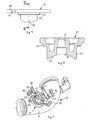
- These and other characteristics of the present invention will become apparent from the following description of a preferential form of embodiment, given as a non-restrictive example with reference to the attached drawings wherein:
-
fig. 1 is a front view of a stop device for a cleaning element in a concrete distribution pipe according to the present invention; -
fig. 2 is an enlarged section view from II to II offig. 1 ; -
fig. 3 is a view from above offig. 1 ; -
fig. 4 is an enlarged view from above of a detail of the stop device according to the present invention; -
fig. 5 is a lateral view offig. 4 ; -
fig. 6 is a section view from VI to VI of the detail infig. 6 ; -
fig. 7 is a three-dimensional view of the stop device coupled with a concrete distribution pipe. - With reference to the attached drawings, a
stop device 13 for a cleaning element for apipe 10 for the distribution of concrete or other material similar to concrete, according to the present invention, is coupled with alateral mouth 20 of thedistribution pipe 10. Thedistribution pipe 10 comprises a plurality ofsegments 11 joined by joints of a known type and constrained byattachment elements 12 to an arm for the distribution of the concrete, for example extendible, mounted on a work vehicle of a known type and not shown in the drawings. At least afirst segment 11 of saiddistribution pipe 10 is connected directly to the work vehicle. - The
lateral mouth 20 of thedistribution pipe 10, with a substantially circular section, is used for the removal of a cleaning element, or ball, shot at high pressure or sucked in at one end of thedistribution pipe 10, so as to clean the internal walls of thedistribution pipe 10 of residues and incrustations by means of scraping, at the end of the delivery of concrete. - The
stop device 13 comprises astopper 14 suitable to be coupled, with a lower portion thereof, in a position to close saidmouth 20, both during the distribution of the concrete and also during the cleaning of thedistribution pipe 10. Thestopper 14 comprises a circular lower portion provided with acircular step 24 resting on thelateral mouth 20 and a cylindrical lateral surface 23 (figs. 5 and 6 ) coupled with the internal cylindrical surface of themouth 20. - The
stopper 14 also comprises ahole 15 able to define, together with ahollow seating 16, a through seating for astop element 17, also denominated hereafter as a stop, and suitable to clamp the ball during the cleaning of the internal wall of thedistribution pipe 10. Thestop 17 is able to slide axially through said through seating between a first position, at least partly outside thedistribution pipe 10, and a second position inside thedistribution pipe 10 and transverse to the direction of advance both of the ball and also of the concrete, so as to stop the advance of the ball during said cleaning. Oneend 18 of thestop 17 is housed in thehollow seating 16 when thestop 17 is disposed in its first position. - According to a characteristic feature of the present invention, the lower portion of the
stopper 14 associated with the internal cavity of the mouth comprises a body suitable to fill, during use, the whole volume defined by said cavity. Furthermore, a lower surface 22 (figs. 2 ,5 and 6 ) of said lower portion of thestopper 14, disposed during use toward the inside of thedistribution pipe 10, is shaped so as to define a continuous profile, together with the shaping of theinternal surface 26 of the wall of thedistribution pipe 10. The continuous profile is such as to be indistinguishable from the internal profile of thedistribution pipe 10 in correspondence with its transverse sections, before or after themouth 20. - In this case the
lower surface 22 of thestopper 14, disposed to close themouth 20, and theinternal surface 26 of thedistribution pipe 10 in correspondence with themouth 20, achieve a single internal profile whose transverse sections, defined by the intersection of planes orthogonal to said direction of advance, are substantially circular and continuous with the cross sections of thedistribution pipe 10 before or after the portion comprising themouth 20. - The
stopper 14 also comprises twoattachment wings 30 with a square or rectangular shape (fig. 4 ), diametrically opposite and protruding with respect to the body of thestopper 14, and suitable to be coupled with an equal number ofcylindrical pins 44, disposed on the external surface of thedistribution pipe 10 in order to clamp thestopper 14 in said closing position. - According to a preferential embodiment the
attachment wings 30 are made in a single piece with the body of thestopper 14. - The
attachment wings 30 cooperate with thepins 44 during a rotation of thestopper 14 in order to dispose it in said position to close themouth 20. Eachattachment wing 30 comprises anti-unscrewing means. In fact, eachattachment wing 30 comprises ahollow seating 32 open on one side of thewing 30 and suitable to cooperate with the associatedpin 44. Thehollow seating 32 comprises an elongated U-shaped profile, rounded at one end suitable for coupling with the lateral surface of thepin 44, and substantially parallel to the external profile of thestopper 14. The transverse size of thehollow seating 32 is at least equal to the transverse thickness of saidpins 44. Eachattachment wing 30 also comprises acircular seating 34, substantially concentric to the terminal portion of saidhollow seating 32, and such as to define, together with the correspondinghollow seating 32, a semi-circular step for the insertion of a corresponding holed end of aclamping handle 40 and suitable to clamp thestopper 14 in the closed position of themouth 20. Theclamping handle 40 is therefore coupled both with thepin 44 and also with thehollow seating 32 in order to prevent the rotation of thestopper 14 from its position where it closes themouth 20. - The
stop device 13 as described heretofore functions as follows. - During the normal delivery of concrete, the
mouth 20 is closed by thestopper 14 in its closing position and with thestop 17 disposed in its first position. - At the end of the delivery of concrete, before the internal walls of the
distribution pipe 10 are cleaned, thestop 17 is disposed in its second position, so as to occupy transversely the seating where the concrete advances, and therefore the ball, and obstruct the advance of the ball in correspondence with themouth 20. - The ball is shot or sucked into the
distribution pipe 10, for example by inverting the direction of functioning of the delivery pump, allowing to clean the walls due to the surface scraping of the ball in contact with the internal wall of thepipe 10. When, at the end of cleaning, the ball is stopped in its advance by thestop 17, thestopper 14 is removed from themouth 20 so as to allow access inside thepipe 10 and the subsequent removal of the ball stopped by thestop 17. In order to remove thestopper 14 from themouth 20, first each clamping handle 40 is removed from the associatedpin 44 and then from thecircular seating 34 of theattachment wing 30. Subsequently, thestopper 14 is rotated so as to disengage eachpin 44 from the correspondinghollow seating 32 of theattachment wing 30. Finally, thestopper 14 is raised and removed from themouth 20 and the ball is removed through themouth 20. - At the end of cleaning the
stopper 14 is again positioned in its position to close themouth 20, performing in inverse sequence the removal operations just described. - It is clear that modifications and/or additions of parts may be made to the
stop device 13 for a cleaning element in apipe 10 for the distribution of concrete as described heretofore, without departing from the field and scope of the present invention. - It is also clear that, although the present invention has been described with reference to some specific examples, a person of skill in the art shall certainly be able to achieve many other equivalent forms of
stop device 13 for a cleaning element in a pipe for the distribution of concrete, having the characteristics as set forth in the claims and hence all coming within the field of protection defined thereby.
Claims (11)
- Stop device for a ball-type cleaning element in a pipe (10) for the distribution of concrete, or of other similar material, comprising:- a stopper (14) able to be coupled with a lateral mouth (20) of said pipe (10), having a lower portion for closing said mouth (20) of said distribution pipe (10) in an operative position thereof,- a stop element (17), elongated in shape and able to be inserted in a hole (15) of said stopper (14) and able to slide between a first position at least partly outside said distribution pipe (10), and a second position inside said distribution pipe (10) and transverse to the direction of advance of said ball-type cleaning element so as to stop it, wherein
said lower portion of said stopper (14) is associated during use with an internal cavity of the mouth (20) and comprises a body able to occupy substantially the whole volume defined inside said mouth (20) characterized in that said lower portion of said stopper (14) comprises a lower surface (22) disposed during use toward the inside of said distribution pipe (10), and arc-shaped so as to define, in correspondence with a segment of the distribution pipe (10) comprising said mouth (20), together with the internal surface (26) of the wall of the distribution pipe, a continuous single internal profile indistinguishable from the internal profile of the distribution pipe (10) and having transverse sections substantially circular and continuous with transverse sections of the distribution pipe (10) before and after said segment of the distribution pipe (10) comprising said mouth (20), and the lateral mouth (20) of said pipe (10) configured to allow the removal of the ball-type cleaning element through it after the ball-type cleaning element has been stopped inside the pipe (10). - Stop device as in claim 1, characterized in that said stopper (14) is removable from said mouth (20) to allow the removal of the ball-type cleaning element.
- Stop device as in any claim hereinbefore, characterized in that said hole (15) comprises a hollow seating (16) able to house one end (18) of said stop element (17) disposed in said first position.
- Stop device as in any claim hereinbefore, characterized in that said stopper (14) comprises attachment elements (30) able to be coupled with associated clamping elements (44) of said distribution pipe (10) in order to clamp said stopper (14) in said operative position for closing said mouth (20).
- Stop device as in claim 4, characterized in that said attachment elements (30) comprise anti-unscrewing means.
- Stop device as in claim or 5, characterized in that said attachment elements (30) of said stopper (14) are made in a single piece.
- Stop device as in any claim from 4 to 6, characterized in that said clamping elements comprise pins (44).
- Stop device as in claim 7, characterized in that said anti-unscrewing means of said attachment elements (30) comprises a hollow seating (32), open, able to cooperate with an associated pin (44) in said closing position, and having a U-shaped profile and a transverse size at least equal to the transverse thickness of said pin (44).
- Stop device as in claim 8, characterized in that said anti-unscrewing means of said attachment elements (30) also comprises a circular seating (34), concentric to one end of the hollow seating (32) so as to define, together with said hollow seating (32), a semi-circular step able to house one end of a clamping handle (40).
- Stop device as in claim 9, characterized in that said end of said clamping handle (40) comprises a hole able to be coupled during use with said circular seating (34), with one of said pins (44) for the anti-unscrewing clamping of said stopper (14) in said closing position.
- Stop device as in any claim hereinbefore, characterized in that the mouth (20) has a substantially circular section for the removal of the ball-type cleaning element and the lower portion of the stopper (14) is provided with a circular step (24) resting on the mouth (20) and a cylindrical lateral surface (23) coupled with the internal cylindrical surface of the mouth (20).
Priority Applications (1)
| Application Number | Priority Date | Filing Date | Title |
|---|---|---|---|
| PL09150628T PL2080567T3 (en) | 2008-01-18 | 2009-01-15 | Stop device for a cleaning element in a pipe for the distribution of concrete |
Applications Claiming Priority (1)
| Application Number | Priority Date | Filing Date | Title |
|---|---|---|---|
| IT000010A ITUD20080010A1 (en) | 2008-01-18 | 2008-01-18 | STOP DEVICE FOR A CLEANING ELEMENT OF A CONCRETE DISTRIBUTION PIPE |
Publications (3)
| Publication Number | Publication Date |
|---|---|
| EP2080567A2 EP2080567A2 (en) | 2009-07-22 |
| EP2080567A3 EP2080567A3 (en) | 2010-05-05 |
| EP2080567B1 true EP2080567B1 (en) | 2011-10-19 |
Family
ID=40290454
Family Applications (1)
| Application Number | Title | Priority Date | Filing Date |
|---|---|---|---|
| EP09150628A Not-in-force EP2080567B1 (en) | 2008-01-18 | 2009-01-15 | Stop device for a cleaning element in a pipe for the distribution of concrete |
Country Status (6)
| Country | Link |
|---|---|
| EP (1) | EP2080567B1 (en) |
| AT (1) | ATE529199T1 (en) |
| DK (1) | DK2080567T3 (en) |
| ES (1) | ES2375432T3 (en) |
| IT (1) | ITUD20080010A1 (en) |
| PL (1) | PL2080567T3 (en) |
Families Citing this family (3)
| Publication number | Priority date | Publication date | Assignee | Title |
|---|---|---|---|---|
| CN109184218B (en) * | 2018-09-20 | 2023-08-08 | 中联重科股份有限公司 | Concrete pumping device and concrete pumping equipment |
| CN112337906B (en) * | 2020-10-16 | 2022-02-18 | 威海玉全新型建筑材料股份有限公司 | Concrete mixing plant with dust removal function and dust removal method thereof |
| CN112792999A (en) * | 2021-01-11 | 2021-05-14 | 崔志明 | Environment-friendly maintenance of equipment for aerated concrete manufacture |
Family Cites Families (5)
| Publication number | Priority date | Publication date | Assignee | Title |
|---|---|---|---|---|
| DE3244380A1 (en) * | 1981-12-10 | 1983-06-16 | Herberts Gmbh, 5600 Wuppertal | Valve for pipelines which can be pigged |
| DE3229103C1 (en) * | 1982-08-04 | 1984-03-01 | WIBAU AG, 6466 Gründau | Cleaning device for emptying and cleaning the feed line of a concrete pump equipped with a charging container |
| US6029302A (en) * | 1995-05-12 | 2000-02-29 | Tuchenhagen Gmbh | Cleanable scraper station |
| JP4235461B2 (en) * | 2003-02-06 | 2009-03-11 | 阪南鉄工株式会社 | Pig stop device |
| DE102005054336A1 (en) * | 2005-11-11 | 2007-05-16 | Schwing Gmbh F | Concrete conveyor with entry fitting for entering a cleaning body |
-
2008
- 2008-01-18 IT IT000010A patent/ITUD20080010A1/en unknown
-
2009
- 2009-01-15 DK DK09150628.7T patent/DK2080567T3/en active
- 2009-01-15 ES ES09150628T patent/ES2375432T3/en active Active
- 2009-01-15 AT AT09150628T patent/ATE529199T1/en active
- 2009-01-15 EP EP09150628A patent/EP2080567B1/en not_active Not-in-force
- 2009-01-15 PL PL09150628T patent/PL2080567T3/en unknown
Also Published As
| Publication number | Publication date |
|---|---|
| ITUD20080010A1 (en) | 2009-07-19 |
| ATE529199T1 (en) | 2011-11-15 |
| EP2080567A3 (en) | 2010-05-05 |
| EP2080567A2 (en) | 2009-07-22 |
| DK2080567T3 (en) | 2012-02-06 |
| ES2375432T3 (en) | 2012-02-29 |
| PL2080567T3 (en) | 2012-03-30 |
Similar Documents
| Publication | Publication Date | Title |
|---|---|---|
| US9631349B2 (en) | Plunger with toilet declogger | |
| US9707936B2 (en) | Wiper system for spraying a cleaning and/or deicing fluid from the region of a windscreen wiper | |
| CN205047233U (en) | Concrete spraying vehicle's injection apparatus and concrete spraying vehicle | |
| CA2610544A1 (en) | Connector for filling concrete formworks | |
| EP2080567A2 (en) | Stop device for a cleaning element in a pipe for the distribution of concrete | |
| EP2372330A1 (en) | Air bubble sensor | |
| KR20130011697A (en) | A cleaning device of a sewage pipe | |
| KR101474298B1 (en) | System and method for reparing conduit in non-excavation manner | |
| CN101329001A (en) | Internal tooth snap ring of fluid pipe connecting device | |
| CN101166863B (en) | Fastening system for use during transport | |
| JP3749140B2 (en) | Wall surface repair method and wall surface repair gun | |
| KR20140146335A (en) | Cleaning device having inflectional cutting tool of ball type shaft | |
| CN211257856U (en) | Concrete conveying pipe material blocking valve | |
| DE102017223518A1 (en) | Wiper blade device | |
| CN207770413U (en) | A kind of automatic preceding line pipe flushing ejecting device | |
| WO2020147994A1 (en) | Wiper blade device | |
| CN204420172U (en) | Scrubbing type welding ball valve | |
| DE4039663C2 (en) | ||
| US1720049A (en) | Paraffin scraper | |
| CN121654812B (en) | Wet-type guniting machine pipeline connecting joint device | |
| CN207405490U (en) | A kind of connection equipment of hole path pressure grouting for bridge prestress | |
| JP4885531B2 (en) | Observation jig and coating method in steel pipe | |
| CN223000521U (en) | Quick dismounting device | |
| KR200237601Y1 (en) | Packer for crack repaying of concrete construction | |
| DE10056253A1 (en) | Cleaning appliance for beverage pipes has connection arrangement with intermediate adapter with screw thread connected to screw connector, for easy addition of cleaning additives |
Legal Events
| Date | Code | Title | Description |
|---|---|---|---|
| PUAI | Public reference made under article 153(3) epc to a published international application that has entered the european phase |
Free format text: ORIGINAL CODE: 0009012 |
|
| AK | Designated contracting states |
Kind code of ref document: A2 Designated state(s): AT BE BG CH CY CZ DE DK EE ES FI FR GB GR HR HU IE IS IT LI LT LU LV MC MK MT NL NO PL PT RO SE SI SK TR |
|
| AX | Request for extension of the european patent |
Extension state: AL BA RS |
|
| PUAL | Search report despatched |
Free format text: ORIGINAL CODE: 0009013 |
|
| AK | Designated contracting states |
Kind code of ref document: A3 Designated state(s): AT BE BG CH CY CZ DE DK EE ES FI FR GB GR HR HU IE IS IT LI LT LU LV MC MK MT NL NO PL PT RO SE SI SK TR |
|
| AX | Request for extension of the european patent |
Extension state: AL BA RS |
|
| 17P | Request for examination filed |
Effective date: 20101104 |
|
| AKX | Designation fees paid |
Designated state(s): AT BE BG CH CY CZ DE DK EE ES FI FR GB GR HR HU IE IS IT LI LT LU LV MC MK MT NL NO PL PT RO SE SI SK TR |
|
| GRAP | Despatch of communication of intention to grant a patent |
Free format text: ORIGINAL CODE: EPIDOSNIGR1 |
|
| RIC1 | Information provided on ipc code assigned before grant |
Ipc: F16L 55/46 20060101ALI20110325BHEP Ipc: B08B 9/055 20060101AFI20110325BHEP |
|
| GRAS | Grant fee paid |
Free format text: ORIGINAL CODE: EPIDOSNIGR3 |
|
| GRAA | (expected) grant |
Free format text: ORIGINAL CODE: 0009210 |
|
| RIN1 | Information on inventor provided before grant (corrected) |
Inventor name: MOSCA, RAFFAELE Inventor name: FERRE, FABIO Inventor name: PIRRI, NICOLA |
|
| AK | Designated contracting states |
Kind code of ref document: B1 Designated state(s): AT BE BG CH CY CZ DE DK EE ES FI FR GB GR HR HU IE IS IT LI LT LU LV MC MK MT NL NO PL PT RO SE SI SK TR |
|
| REG | Reference to a national code |
Ref country code: GB Ref legal event code: FG4D |
|
| REG | Reference to a national code |
Ref country code: CH Ref legal event code: EP |
|
| REG | Reference to a national code |
Ref country code: IE Ref legal event code: FG4D |
|
| REG | Reference to a national code |
Ref country code: CH Ref legal event code: NV Representative=s name: MICHELI & CIE SA |
|
| REG | Reference to a national code |
Ref country code: DE Ref legal event code: R096 Ref document number: 602009003127 Country of ref document: DE Effective date: 20120119 |
|
| REG | Reference to a national code |
Ref country code: NL Ref legal event code: T3 |
|
| REG | Reference to a national code |
Ref country code: DK Ref legal event code: T3 |
|
| REG | Reference to a national code |
Ref country code: SE Ref legal event code: TRGR |
|
| REG | Reference to a national code |
Ref country code: ES Ref legal event code: FG2A Ref document number: 2375432 Country of ref document: ES Kind code of ref document: T3 Effective date: 20120229 |
|
| LTIE | Lt: invalidation of european patent or patent extension |
Effective date: 20111019 |
|
| REG | Reference to a national code |
Ref country code: PL Ref legal event code: T3 |
|
| REG | Reference to a national code |
Ref country code: GR Ref legal event code: EP Ref document number: 20120400119 Country of ref document: GR Effective date: 20120305 |
|
| PG25 | Lapsed in a contracting state [announced via postgrant information from national office to epo] |
Ref country code: IS Free format text: LAPSE BECAUSE OF FAILURE TO SUBMIT A TRANSLATION OF THE DESCRIPTION OR TO PAY THE FEE WITHIN THE PRESCRIBED TIME-LIMIT Effective date: 20120219 Ref country code: LT Free format text: LAPSE BECAUSE OF FAILURE TO SUBMIT A TRANSLATION OF THE DESCRIPTION OR TO PAY THE FEE WITHIN THE PRESCRIBED TIME-LIMIT Effective date: 20111019 Ref country code: NO Free format text: LAPSE BECAUSE OF FAILURE TO SUBMIT A TRANSLATION OF THE DESCRIPTION OR TO PAY THE FEE WITHIN THE PRESCRIBED TIME-LIMIT Effective date: 20120119 |
|
| PG25 | Lapsed in a contracting state [announced via postgrant information from national office to epo] |
Ref country code: LV Free format text: LAPSE BECAUSE OF FAILURE TO SUBMIT A TRANSLATION OF THE DESCRIPTION OR TO PAY THE FEE WITHIN THE PRESCRIBED TIME-LIMIT Effective date: 20111019 Ref country code: SI Free format text: LAPSE BECAUSE OF FAILURE TO SUBMIT A TRANSLATION OF THE DESCRIPTION OR TO PAY THE FEE WITHIN THE PRESCRIBED TIME-LIMIT Effective date: 20111019 Ref country code: HR Free format text: LAPSE BECAUSE OF FAILURE TO SUBMIT A TRANSLATION OF THE DESCRIPTION OR TO PAY THE FEE WITHIN THE PRESCRIBED TIME-LIMIT Effective date: 20111019 Ref country code: PT Free format text: LAPSE BECAUSE OF FAILURE TO SUBMIT A TRANSLATION OF THE DESCRIPTION OR TO PAY THE FEE WITHIN THE PRESCRIBED TIME-LIMIT Effective date: 20120220 |
|
| PG25 | Lapsed in a contracting state [announced via postgrant information from national office to epo] |
Ref country code: CY Free format text: LAPSE BECAUSE OF FAILURE TO SUBMIT A TRANSLATION OF THE DESCRIPTION OR TO PAY THE FEE WITHIN THE PRESCRIBED TIME-LIMIT Effective date: 20111019 |
|
| PG25 | Lapsed in a contracting state [announced via postgrant information from national office to epo] |
Ref country code: EE Free format text: LAPSE BECAUSE OF FAILURE TO SUBMIT A TRANSLATION OF THE DESCRIPTION OR TO PAY THE FEE WITHIN THE PRESCRIBED TIME-LIMIT Effective date: 20111019 Ref country code: SK Free format text: LAPSE BECAUSE OF FAILURE TO SUBMIT A TRANSLATION OF THE DESCRIPTION OR TO PAY THE FEE WITHIN THE PRESCRIBED TIME-LIMIT Effective date: 20111019 Ref country code: CZ Free format text: LAPSE BECAUSE OF FAILURE TO SUBMIT A TRANSLATION OF THE DESCRIPTION OR TO PAY THE FEE WITHIN THE PRESCRIBED TIME-LIMIT Effective date: 20111019 Ref country code: BG Free format text: LAPSE BECAUSE OF FAILURE TO SUBMIT A TRANSLATION OF THE DESCRIPTION OR TO PAY THE FEE WITHIN THE PRESCRIBED TIME-LIMIT Effective date: 20120119 |
|
| PLBE | No opposition filed within time limit |
Free format text: ORIGINAL CODE: 0009261 |
|
| STAA | Information on the status of an ep patent application or granted ep patent |
Free format text: STATUS: NO OPPOSITION FILED WITHIN TIME LIMIT |
|
| PG25 | Lapsed in a contracting state [announced via postgrant information from national office to epo] |
Ref country code: RO Free format text: LAPSE BECAUSE OF FAILURE TO SUBMIT A TRANSLATION OF THE DESCRIPTION OR TO PAY THE FEE WITHIN THE PRESCRIBED TIME-LIMIT Effective date: 20111019 Ref country code: MC Free format text: LAPSE BECAUSE OF NON-PAYMENT OF DUE FEES Effective date: 20120131 |
|
| 26N | No opposition filed |
Effective date: 20120720 |
|
| REG | Reference to a national code |
Ref country code: IE Ref legal event code: MM4A |
|
| REG | Reference to a national code |
Ref country code: DE Ref legal event code: R097 Ref document number: 602009003127 Country of ref document: DE Effective date: 20120720 |
|
| PG25 | Lapsed in a contracting state [announced via postgrant information from national office to epo] |
Ref country code: IE Free format text: LAPSE BECAUSE OF NON-PAYMENT OF DUE FEES Effective date: 20120115 |
|
| PG25 | Lapsed in a contracting state [announced via postgrant information from national office to epo] |
Ref country code: MK Free format text: LAPSE BECAUSE OF FAILURE TO SUBMIT A TRANSLATION OF THE DESCRIPTION OR TO PAY THE FEE WITHIN THE PRESCRIBED TIME-LIMIT Effective date: 20111019 |
|
| PGFP | Annual fee paid to national office [announced via postgrant information from national office to epo] |
Ref country code: GB Payment date: 20130122 Year of fee payment: 5 Ref country code: FI Payment date: 20130111 Year of fee payment: 5 Ref country code: SE Payment date: 20130122 Year of fee payment: 5 Ref country code: DK Payment date: 20130121 Year of fee payment: 5 |
|
| PGFP | Annual fee paid to national office [announced via postgrant information from national office to epo] |
Ref country code: PL Payment date: 20130111 Year of fee payment: 5 Ref country code: GR Payment date: 20130117 Year of fee payment: 5 |
|
| PG25 | Lapsed in a contracting state [announced via postgrant information from national office to epo] |
Ref country code: MT Free format text: LAPSE BECAUSE OF FAILURE TO SUBMIT A TRANSLATION OF THE DESCRIPTION OR TO PAY THE FEE WITHIN THE PRESCRIBED TIME-LIMIT Effective date: 20111019 |
|
| PG25 | Lapsed in a contracting state [announced via postgrant information from national office to epo] |
Ref country code: LU Free format text: LAPSE BECAUSE OF NON-PAYMENT OF DUE FEES Effective date: 20120115 |
|
| PG25 | Lapsed in a contracting state [announced via postgrant information from national office to epo] |
Ref country code: HU Free format text: LAPSE BECAUSE OF FAILURE TO SUBMIT A TRANSLATION OF THE DESCRIPTION OR TO PAY THE FEE WITHIN THE PRESCRIBED TIME-LIMIT Effective date: 20090115 |
|
| REG | Reference to a national code |
Ref country code: DK Ref legal event code: EBP Effective date: 20140131 |
|
| REG | Reference to a national code |
Ref country code: SE Ref legal event code: EUG |
|
| GBPC | Gb: european patent ceased through non-payment of renewal fee |
Effective date: 20140115 |
|
| REG | Reference to a national code |
Ref country code: GR Ref legal event code: ML Ref document number: 20120400119 Country of ref document: GR Effective date: 20140801 |
|
| PG25 | Lapsed in a contracting state [announced via postgrant information from national office to epo] |
Ref country code: GR Free format text: LAPSE BECAUSE OF NON-PAYMENT OF DUE FEES Effective date: 20140801 Ref country code: FI Free format text: LAPSE BECAUSE OF NON-PAYMENT OF DUE FEES Effective date: 20140115 |
|
| PG25 | Lapsed in a contracting state [announced via postgrant information from national office to epo] |
Ref country code: GB Free format text: LAPSE BECAUSE OF NON-PAYMENT OF DUE FEES Effective date: 20140115 Ref country code: SE Free format text: LAPSE BECAUSE OF NON-PAYMENT OF DUE FEES Effective date: 20140116 |
|
| PG25 | Lapsed in a contracting state [announced via postgrant information from national office to epo] |
Ref country code: DK Free format text: LAPSE BECAUSE OF NON-PAYMENT OF DUE FEES Effective date: 20140131 |
|
| REG | Reference to a national code |
Ref country code: PL Ref legal event code: LAPE |
|
| PG25 | Lapsed in a contracting state [announced via postgrant information from national office to epo] |
Ref country code: PL Free format text: LAPSE BECAUSE OF NON-PAYMENT OF DUE FEES Effective date: 20140115 |
|
| REG | Reference to a national code |
Ref country code: FR Ref legal event code: PLFP Year of fee payment: 8 |
|
| PGFP | Annual fee paid to national office [announced via postgrant information from national office to epo] |
Ref country code: NL Payment date: 20160120 Year of fee payment: 8 |
|
| PGFP | Annual fee paid to national office [announced via postgrant information from national office to epo] |
Ref country code: ES Payment date: 20160112 Year of fee payment: 8 |
|
| PGFP | Annual fee paid to national office [announced via postgrant information from national office to epo] |
Ref country code: BE Payment date: 20160120 Year of fee payment: 8 |
|
| REG | Reference to a national code |
Ref country code: FR Ref legal event code: PLFP Year of fee payment: 9 |
|
| PG25 | Lapsed in a contracting state [announced via postgrant information from national office to epo] |
Ref country code: BE Free format text: LAPSE BECAUSE OF NON-PAYMENT OF DUE FEES Effective date: 20170131 |
|
| REG | Reference to a national code |
Ref country code: NL Ref legal event code: MM Effective date: 20170201 |
|
| PG25 | Lapsed in a contracting state [announced via postgrant information from national office to epo] |
Ref country code: NL Free format text: LAPSE BECAUSE OF NON-PAYMENT OF DUE FEES Effective date: 20170201 |
|
| REG | Reference to a national code |
Ref country code: FR Ref legal event code: PLFP Year of fee payment: 10 |
|
| REG | Reference to a national code |
Ref country code: BE Ref legal event code: MM Effective date: 20170131 |
|
| PGFP | Annual fee paid to national office [announced via postgrant information from national office to epo] |
Ref country code: DE Payment date: 20180122 Year of fee payment: 10 Ref country code: CH Payment date: 20180119 Year of fee payment: 10 |
|
| PG25 | Lapsed in a contracting state [announced via postgrant information from national office to epo] |
Ref country code: ES Free format text: LAPSE BECAUSE OF NON-PAYMENT OF DUE FEES Effective date: 20170116 |
|
| PGFP | Annual fee paid to national office [announced via postgrant information from national office to epo] |
Ref country code: FR Payment date: 20180119 Year of fee payment: 10 Ref country code: IT Payment date: 20180116 Year of fee payment: 10 Ref country code: AT Payment date: 20180122 Year of fee payment: 10 Ref country code: TR Payment date: 20180112 Year of fee payment: 10 |
|
| REG | Reference to a national code |
Ref country code: ES Ref legal event code: FD2A Effective date: 20180620 |
|
| REG | Reference to a national code |
Ref country code: DE Ref legal event code: R119 Ref document number: 602009003127 Country of ref document: DE |
|
| REG | Reference to a national code |
Ref country code: CH Ref legal event code: PL |
|
| REG | Reference to a national code |
Ref country code: AT Ref legal event code: MM01 Ref document number: 529199 Country of ref document: AT Kind code of ref document: T Effective date: 20190115 |
|
| PG25 | Lapsed in a contracting state [announced via postgrant information from national office to epo] |
Ref country code: DE Free format text: LAPSE BECAUSE OF NON-PAYMENT OF DUE FEES Effective date: 20190801 Ref country code: FR Free format text: LAPSE BECAUSE OF NON-PAYMENT OF DUE FEES Effective date: 20190131 |
|
| PG25 | Lapsed in a contracting state [announced via postgrant information from national office to epo] |
Ref country code: AT Free format text: LAPSE BECAUSE OF NON-PAYMENT OF DUE FEES Effective date: 20190115 Ref country code: LI Free format text: LAPSE BECAUSE OF NON-PAYMENT OF DUE FEES Effective date: 20190131 Ref country code: CH Free format text: LAPSE BECAUSE OF NON-PAYMENT OF DUE FEES Effective date: 20190131 |
|
| PG25 | Lapsed in a contracting state [announced via postgrant information from national office to epo] |
Ref country code: IT Free format text: LAPSE BECAUSE OF NON-PAYMENT OF DUE FEES Effective date: 20190115 |
|
| PG25 | Lapsed in a contracting state [announced via postgrant information from national office to epo] |
Ref country code: TR Free format text: LAPSE BECAUSE OF NON-PAYMENT OF DUE FEES Effective date: 20190115 |