EP2079161A1 - Alternating current motor drive circuit and electric vehicle drive circuit - Google Patents
Alternating current motor drive circuit and electric vehicle drive circuit Download PDFInfo
- Publication number
- EP2079161A1 EP2079161A1 EP09150122A EP09150122A EP2079161A1 EP 2079161 A1 EP2079161 A1 EP 2079161A1 EP 09150122 A EP09150122 A EP 09150122A EP 09150122 A EP09150122 A EP 09150122A EP 2079161 A1 EP2079161 A1 EP 2079161A1
- Authority
- EP
- European Patent Office
- Prior art keywords
- alternating current
- drive circuit
- current motor
- rectifier
- circuit
- Prior art date
- Legal status (The legal status is an assumption and is not a legal conclusion. Google has not performed a legal analysis and makes no representation as to the accuracy of the status listed.)
- Granted
Links
Images



Classifications
-
- H—ELECTRICITY
- H02—GENERATION; CONVERSION OR DISTRIBUTION OF ELECTRIC POWER
- H02P—CONTROL OR REGULATION OF ELECTRIC MOTORS, ELECTRIC GENERATORS OR DYNAMO-ELECTRIC CONVERTERS; CONTROLLING TRANSFORMERS, REACTORS OR CHOKE COILS
- H02P27/00—Arrangements or methods for the control of AC motors characterised by the kind of supply voltage
- H02P27/04—Arrangements or methods for the control of AC motors characterised by the kind of supply voltage using variable-frequency supply voltage, e.g. inverter or converter supply voltage
-
- B—PERFORMING OPERATIONS; TRANSPORTING
- B60—VEHICLES IN GENERAL
- B60L—PROPULSION OF ELECTRICALLY-PROPELLED VEHICLES; SUPPLYING ELECTRIC POWER FOR AUXILIARY EQUIPMENT OF ELECTRICALLY-PROPELLED VEHICLES; ELECTRODYNAMIC BRAKE SYSTEMS FOR VEHICLES IN GENERAL; MAGNETIC SUSPENSION OR LEVITATION FOR VEHICLES; MONITORING OPERATING VARIABLES OF ELECTRICALLY-PROPELLED VEHICLES; ELECTRIC SAFETY DEVICES FOR ELECTRICALLY-PROPELLED VEHICLES
- B60L50/00—Electric propulsion with power supplied within the vehicle
- B60L50/50—Electric propulsion with power supplied within the vehicle using propulsion power supplied by batteries or fuel cells
- B60L50/60—Electric propulsion with power supplied within the vehicle using propulsion power supplied by batteries or fuel cells using power supplied by batteries
-
- H—ELECTRICITY
- H02—GENERATION; CONVERSION OR DISTRIBUTION OF ELECTRIC POWER
- H02M—APPARATUS FOR CONVERSION BETWEEN AC AND AC, BETWEEN AC AND DC, OR BETWEEN DC AND DC, AND FOR USE WITH MAINS OR SIMILAR POWER SUPPLY SYSTEMS; CONVERSION OF DC OR AC INPUT POWER INTO SURGE OUTPUT POWER; CONTROL OR REGULATION THEREOF
- H02M7/00—Conversion of AC power input into DC power output; Conversion of DC power input into AC power output
- H02M7/02—Conversion of AC power input into DC power output without possibility of reversal
- H02M7/04—Conversion of AC power input into DC power output without possibility of reversal by static converters
- H02M7/12—Conversion of AC power input into DC power output without possibility of reversal by static converters using discharge tubes with control electrode or semiconductor devices with control electrode
- H02M7/21—Conversion of AC power input into DC power output without possibility of reversal by static converters using discharge tubes with control electrode or semiconductor devices with control electrode using devices of a triode or transistor type requiring continuous application of a control signal
- H02M7/217—Conversion of AC power input into DC power output without possibility of reversal by static converters using discharge tubes with control electrode or semiconductor devices with control electrode using devices of a triode or transistor type requiring continuous application of a control signal using semiconductor devices only
-
- H—ELECTRICITY
- H02—GENERATION; CONVERSION OR DISTRIBUTION OF ELECTRIC POWER
- H02P—CONTROL OR REGULATION OF ELECTRIC MOTORS, ELECTRIC GENERATORS OR DYNAMO-ELECTRIC CONVERTERS; CONTROLLING TRANSFORMERS, REACTORS OR CHOKE COILS
- H02P9/00—Arrangements for controlling electric generators for the purpose of obtaining a desired output
- H02P9/48—Arrangements for obtaining a constant output value at varying speed of the generator, e.g. on vehicle
-
- B—PERFORMING OPERATIONS; TRANSPORTING
- B60—VEHICLES IN GENERAL
- B60L—PROPULSION OF ELECTRICALLY-PROPELLED VEHICLES; SUPPLYING ELECTRIC POWER FOR AUXILIARY EQUIPMENT OF ELECTRICALLY-PROPELLED VEHICLES; ELECTRODYNAMIC BRAKE SYSTEMS FOR VEHICLES IN GENERAL; MAGNETIC SUSPENSION OR LEVITATION FOR VEHICLES; MONITORING OPERATING VARIABLES OF ELECTRICALLY-PROPELLED VEHICLES; ELECTRIC SAFETY DEVICES FOR ELECTRICALLY-PROPELLED VEHICLES
- B60L2210/00—Converter types
- B60L2210/20—AC to AC converters
-
- B—PERFORMING OPERATIONS; TRANSPORTING
- B60—VEHICLES IN GENERAL
- B60L—PROPULSION OF ELECTRICALLY-PROPELLED VEHICLES; SUPPLYING ELECTRIC POWER FOR AUXILIARY EQUIPMENT OF ELECTRICALLY-PROPELLED VEHICLES; ELECTRODYNAMIC BRAKE SYSTEMS FOR VEHICLES IN GENERAL; MAGNETIC SUSPENSION OR LEVITATION FOR VEHICLES; MONITORING OPERATING VARIABLES OF ELECTRICALLY-PROPELLED VEHICLES; ELECTRIC SAFETY DEVICES FOR ELECTRICALLY-PROPELLED VEHICLES
- B60L2210/00—Converter types
- B60L2210/40—DC to AC converters
- B60L2210/42—Voltage source inverters
-
- Y—GENERAL TAGGING OF NEW TECHNOLOGICAL DEVELOPMENTS; GENERAL TAGGING OF CROSS-SECTIONAL TECHNOLOGIES SPANNING OVER SEVERAL SECTIONS OF THE IPC; TECHNICAL SUBJECTS COVERED BY FORMER USPC CROSS-REFERENCE ART COLLECTIONS [XRACs] AND DIGESTS
- Y02—TECHNOLOGIES OR APPLICATIONS FOR MITIGATION OR ADAPTATION AGAINST CLIMATE CHANGE
- Y02T—CLIMATE CHANGE MITIGATION TECHNOLOGIES RELATED TO TRANSPORTATION
- Y02T10/00—Road transport of goods or passengers
- Y02T10/60—Other road transportation technologies with climate change mitigation effect
- Y02T10/64—Electric machine technologies in electromobility
-
- Y—GENERAL TAGGING OF NEW TECHNOLOGICAL DEVELOPMENTS; GENERAL TAGGING OF CROSS-SECTIONAL TECHNOLOGIES SPANNING OVER SEVERAL SECTIONS OF THE IPC; TECHNICAL SUBJECTS COVERED BY FORMER USPC CROSS-REFERENCE ART COLLECTIONS [XRACs] AND DIGESTS
- Y02—TECHNOLOGIES OR APPLICATIONS FOR MITIGATION OR ADAPTATION AGAINST CLIMATE CHANGE
- Y02T—CLIMATE CHANGE MITIGATION TECHNOLOGIES RELATED TO TRANSPORTATION
- Y02T10/00—Road transport of goods or passengers
- Y02T10/60—Other road transportation technologies with climate change mitigation effect
- Y02T10/70—Energy storage systems for electromobility, e.g. batteries
-
- Y—GENERAL TAGGING OF NEW TECHNOLOGICAL DEVELOPMENTS; GENERAL TAGGING OF CROSS-SECTIONAL TECHNOLOGIES SPANNING OVER SEVERAL SECTIONS OF THE IPC; TECHNICAL SUBJECTS COVERED BY FORMER USPC CROSS-REFERENCE ART COLLECTIONS [XRACs] AND DIGESTS
- Y02—TECHNOLOGIES OR APPLICATIONS FOR MITIGATION OR ADAPTATION AGAINST CLIMATE CHANGE
- Y02T—CLIMATE CHANGE MITIGATION TECHNOLOGIES RELATED TO TRANSPORTATION
- Y02T10/00—Road transport of goods or passengers
- Y02T10/60—Other road transportation technologies with climate change mitigation effect
- Y02T10/72—Electric energy management in electromobility
Definitions
- the present invention relates to an alternating current motor drive circuit which drives an alternating current motor, using an alternating current generator and a direct current power source capable of a power supply and absorption, and to an electric vehicle drive circuit using the drive circuit.
- Fig. 10 is a circuit diagram showing a first conventional example, in which a three-phase output of an alternating current generator M2 is converted into a direct current by a voltage source rectifier 31 in which arms having switching elements connected in inverse parallel to diodes are bridge-connected, and the voltage of the direct current is smoothed by a capacitor 13. Also, a direct current chopper 12 is provided between the smoothed direct current (connection points N1 and N2) and a battery B, and a power exchange between them is carried out. Furthermore, using the direct current, an alternating current motor M1 is driven by a voltage source inverter 14 in which arms having switching elements (Q3 to Q8) connected in inverse parallel to diodes (D3 to D8) are bridge-connected.
- Fig. 11 is a circuit diagram showing a second conventional example, realizing a power conversion between motor generators MG1 and MG2, using a matrix converter 38. Furthermore, in order to exchange power with a battery 12, a voltage source inverter 36 and a direct current chopper 32 are provided.
- Fig. 12 is a circuit diagram showing a third conventional example, and this circuit can be used when a battery voltage is lower than a direct current link voltage.
- a direct current link capacitor is omitted, but a reactor is connected.
- a reference potential of a battery is a negative side potential of the direct current link, and the battery is not connected to a neutral point of a motor or generator.
- an object of the invention is to particularly eliminate a need for a reactor in a direct current chopper, and achieve a downsizing of the circuit.
- an invention of claim 1 provides in an alternating current motor drive circuit which, including therein an alternating current generator and a direct current power source capable of a power supply and absorption, drives an alternating current motor, in which a current source rectifier being provided at an output of the alternating current generator, the alternating current motor is connected to an output of the rectifier via a voltage source inverter, two arms having switching elements connected in inverse parallel to diodes are connected in series to the output of the rectifier, and one terminal of the direct current power source is connected to a midpoint between the arms, while the other terminal is connected to a neutral point of coils of the alternating current motor.
- the current source rectifier in the invention of claim 1 or 2, it is possible for the current source rectifier to be configured by bridge-connecting bidirectional switches, and have a filter circuit provided on an alternating current input side (an invention of claim 3), or it is possible for the current source rectifier circuit to be configured by bridge-connecting unidirectional switches having a reverse blocking capability, and have a filter circuit provided on an alternating current input side (an invention of claim 4).
- Fig. 1 is a configuration diagram showing an embodiment of the invention.
- a current source rectifier 2 and a voltage source inverter 3 are connected to an output of a three-phase alternating current generator 1, and an alternating current motor 4 is driven by the output thereof.
- the combination of the current source rectifier 2 and voltage source inverter 3 being called, for example, an Indirect Matrix Converter, as disclosed in Non-patent Document 2, by employing a current source rectifier as a rectifier, a need for a large part, such as the capacitor 13 shown in Fig. 10 , is eliminated.
- two arms 6 having switching elements 6a connected in inverse parallel to diodes 6b are connected in series to an output of the rectifier 2. Furthermore, a positive terminal of a storage battery 5 is connected to a midpoint between the two series-connected arms 6, while a negative terminal thereof is connected to a neutral point of the alternating current motor 4.
- the storage battery 5 is used as a direct current power source capable of a power supply and absorption, but it goes without saying that it is possible, in its place, to use a capacitor or a direct current power source to which a storage battery or the like is connected via a DC-DC converter such as a direct current chopper capable of a bidirectional power conversion.
- a power conversion between an output of the alternating current generator 1 and an input of the alternating current motor 4 is realized by, after once converting power into a direct current by means of the current source rectifier 2, converting it into an alternating current by means of the voltage source inverter 3. Also, a power conversion between the storage battery 5 and the output of the rectifier 2 is realized by controlling a zero vectors of the voltage source inverter 3by means of a switching of each arm thereof, as well as appropriately carrying out the switching of the two series-connected arms 6.
- Fig. 2 shows a first modification example of Fig. 1 .
- Fig. 1 it is different from Fig. 1 in that one terminal of the storage battery 5 is connected to a neutral point of the alternating current generator 1, rather than to the neutral point of the alternating current motor 4.
- this circuit by appropriately carrying out the switching of the two series-connected arms 6 and the switches in the rectifier 2, the power conversion between the storage battery 5 and the output of the rectifier 2 being possible, the powering operation and braking operation of the alternating current motor 4 are possible in the same way as in Fig. 1 .
- Fig. 3 shows a second modification example of Fig. 1 .
- This circuit has a feature in that a filter circuit 2a is provided at the input of the current source rectifier 2, and bidirectional switches 2b are bridge-connected. Also, in the voltage source inverter 3 too, individual arms are embodied by switching elements 3a and diodes 3b.
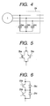
- the filter circuit 2a can be configured by, for example, star-connecting capacitors 2aa, as in Fig. 4 , utilizing an inductance of coils of the alternating current generator 1.
- switching elements 2ba having a reverse blocking capability in themselves are connected, as shown in Fig. 5 .
- Fig. 7 shows a third modification example of Fig. 1 .
- the bidirectional switches 2b of Fig. 3 are replaced with unidirectional switches 2c having a reverse blocking capability. Instead of so doing, it can also be configured of a circuit in which switching elements having no reverse blocking capability are connected in series with diodes.
- Fig. 8 shows a fourth modification example of Fig. 1 .
- This is configured by adding a reactor 7, as an impedance, to the circuit of Fig. 1 . It is also acceptable to add the reactor 7 between the storage battery 5 and the midpoint between the arms 6. Also, it is possible to add the reactor 7 between the storage battery 5 and the generator 1, or between the storage battery 5 and the midpoint between the arms 6, shown in the circuit of Fig. 2 .
- the reactor 7 is a small one having an inductance lower than the inductance of the a conventional chopper.
- the chopper circuit using the inductance component of the coils of the alternating current motor 4 and the two series-connected arms 6 is formed but, depending on a capacity of a selected motor, it may happen that an inductance component of coils of an alternating current motor is low (or high), interfering with a chopper operation.
- an impedance is added to a path between the coils of the alternating current motor and a storage battery, adjusting the inductance to become a size suitable for the chopper operation.
- the above-described example is the one in which, in order to compensate the deficiency, a small reactor is connected in series.
- Fig. 9 shows an application example of Fig. 1 .
- This is the one in which an electric vehicle drive circuit is formed by adding an internal combustion engine 8 to Fig. 1 , mechanically connecting it to the alternating current generator 1, and mechanically connecting a wheel 10 to an output shaft of the alternating current motor 4 to via a gear 9.
- the internal combustion engine 8 can be applied to the circuit of Fig. 2 too.
Landscapes
- Engineering & Computer Science (AREA)
- Power Engineering (AREA)
- Life Sciences & Earth Sciences (AREA)
- Sustainable Development (AREA)
- Sustainable Energy (AREA)
- Transportation (AREA)
- Mechanical Engineering (AREA)
- Electric Propulsion And Braking For Vehicles (AREA)
- Control Of Ac Motors In General (AREA)
- Inverter Devices (AREA)
Abstract
Description
- The present invention relates to an alternating current motor drive circuit which drives an alternating current motor, using an alternating current generator and a direct current power source capable of a power supply and absorption, and to an electric vehicle drive circuit using the drive circuit.
- To date, as this kind of circuit, a circuit shown in
Fig. 10 has been known (for example,Patent Document 1 described below). -
Fig. 10 is a circuit diagram showing a first conventional example, in which a three-phase output of an alternating current generator M2 is converted into a direct current by avoltage source rectifier 31 in which arms having switching elements connected in inverse parallel to diodes are bridge-connected, and the voltage of the direct current is smoothed by a capacitor 13. Also, a directcurrent chopper 12 is provided between the smoothed direct current (connection points N1 and N2) and a battery B, and a power exchange between them is carried out. Furthermore, using the direct current, an alternating current motor M1 is driven by avoltage source inverter 14 in which arms having switching elements (Q3 to Q8) connected in inverse parallel to diodes (D3 to D8) are bridge-connected. - Meanwhile, as an example in which an output of an alternating current generator is directly converted into an alternating current by a matrix converter, and fed to an alternating current motor, a circuit shown in
Fig. 11 is also known (for example,Patent Document 2 described below). -
Fig. 11 is a circuit diagram showing a second conventional example, realizing a power conversion between motor generators MG1 and MG2, using amatrix converter 38. Furthermore, in order to exchange power with abattery 12, avoltage source inverter 36 and a directcurrent chopper 32 are provided. - In the meantime, in
Fig. 10 , a large-capacity version of the capacitor 13 being needed for smoothing a direct current, it is difficult to downsize the circuit. Also, a reactor L1 being needed in the directcurrent chopper 12, there is a problem in that the circuit becomes larger due to this too. - Meanwhile, also in
Fig. 11 , a large direct current capacitor C2 being needed between thebattery 12 and the motor generator MG2, it is difficult to downsize the circuit. Also, a reactor L1 being needed in the directcurrent chopper circuit 32, there is a problem in that the circuit becomes larger due to this too. - Accordingly, although not otherwise specified as being for an electric vehicle, the circuit shown in
Fig. 12 is also proposed (Non-patent Document 1 (described below),Fig. 2(a) ).Fig. 12 is a circuit diagram showing a third conventional example, and this circuit can be used when a battery voltage is lower than a direct current link voltage. In the circuit ofFig. 12 , a direct current link capacitor is omitted, but a reactor is connected. In this circuit a reference potential of a battery is a negative side potential of the direct current link, and the battery is not connected to a neutral point of a motor or generator. - [Patent Document 1]
JP-A-2004-112883 - [Patent Document 2]
JP-A-2005-318731 - [Non-patent Document 1] Institute of Electrical Engineers of Japan, The Papers of Technical Meeting on Semiconductor Power Conversion SPC-06-155, pp. 51-55, "A Control Method of AC and DC Power Supply Direct Interface Converters"
- [Non-patent Document 2] Institute of Electrical Engineers of Japan Transactions on Industry Application, Vol. 126, No. 9, pp. 1161-1170, "Technical Trends of Direct Ac/AC Converters"
- Consequently, an object of the invention is to particularly eliminate a need for a reactor in a direct current chopper, and achieve a downsizing of the circuit.
- In order to solve this kind of problem, an invention of
claim 1 provides in an alternating current motor drive circuit which, including therein an alternating current generator and a direct current power source capable of a power supply and absorption, drives an alternating current motor, in which a current source rectifier being provided at an output of the alternating current generator, the alternating current motor is connected to an output of the rectifier via a voltage source inverter, two arms having switching elements connected in inverse parallel to diodes are connected in series to the output of the rectifier, and one terminal of the direct current power source is connected to a midpoint between the arms, while the other terminal is connected to a neutral point of coils of the alternating current motor. - In the invention of
claim 1, it is possible, instead of connecting the other terminal of the direct current power source to the neutral point of the alternating current motor coils, to connect it to a neutral point of coils of the alternating current generator (an invention of claim 2). - In the invention of
claim - In the invention of any one of
claims 1 to 4, it is possible to add an impedance between the direct current power source and any one of the midpoint between the arms, the neutral point of the alternating current motor coils, or the neutral point of the alternating current generator coils (an invention of claim 5). Furthermore, it is possible to form an electric vehicle drive circuit by using the alternating current motor drive circuit according to any one ofclaims 1 to 5 which drives the alternating current generator by means of an internal combustion engine (an invention of claim 6). - According to the inventions of
claims - According to the invention of
claim 3, in an application in which there is a case of causing the current source rectifier to regenerate power to the alternating current generator (.1), it is possible to realize the drive circuit with a simple circuit configuration. Also, as the number of switches to be passed in a path through which a current flows is as small as two in the rectifier, a power conversion is efficient, too. - According to the invention of
claim 4, in an application not causing the current source rectifier to regenerate power to the alternating current generator (.2), it is possible to form a circuit still simpler than that of the invention ofclaim 3. - According to the invention of
claim 5, it being possible to downsize the alternating current generator or the alternating current motor, it is possible to reduce the total size of the drive system including them. - According to the invention of
claim 6, although in an electric vehicle drive circuit of a hybrid vehicle or the like, it is necessary to mount the circuit in a limited space, no large reactor is needed in the circuit of the invention, and thus it is possible to mount a circuit which produces a high output, which makes it possible to improve an acceleration and deceleration performance of an electric vehicle. -
-
Fig. 1 is a circuit diagram showing an embodiment of the invention; -
Fig. 2 is a circuit diagram showing a first modification example ofFig. 1 ; -
Fig. 3 is a circuit diagram showing a second modification example ofFig. 1 ; -
Fig. 4 is a circuit diagram showing a first specific example of a filter circuit used inFig. 3 ; -
Fig. 5 is a circuit diagram showing a first specific example of bidirectional switches used inFig. 3 ; -
Fig. 6 is a circuit diagram showing a second specific example of the bidirectional switches used inFig. 3 ; -
Fig. 7 is a circuit diagram showing a third modification example ofFig. 1 ; -
Fig. 8 is a circuit diagram showing a fourth modification example ofFig. 1 ; -
Fig. 9 is a circuit diagram showing an application example ofFig. 1 ; -
Fig. 10 is a circuit diagram showing a first conventional example; -
Fig. 11 is a circuit diagram showing a second conventional example; and -
Fig. 12 is a circuit diagram showing a third conventional example. -
Fig. 1 is a configuration diagram showing an embodiment of the invention. - As shown in the figure, in this example, a
current source rectifier 2 and avoltage source inverter 3 are connected to an output of a three-phasealternating current generator 1, and an alternatingcurrent motor 4 is driven by the output thereof. The combination of thecurrent source rectifier 2 andvoltage source inverter 3 being called, for example, an Indirect Matrix Converter, as disclosed inNon-patent Document 2, by employing a current source rectifier as a rectifier, a need for a large part, such as the capacitor 13 shown inFig. 10 , is eliminated. - Also, two
arms 6 having switchingelements 6a connected in inverse parallel todiodes 6b are connected in series to an output of therectifier 2. Furthermore, a positive terminal of astorage battery 5 is connected to a midpoint between the two series-connectedarms 6, while a negative terminal thereof is connected to a neutral point of the alternatingcurrent motor 4. Herein, in this example, thestorage battery 5 is used as a direct current power source capable of a power supply and absorption, but it goes without saying that it is possible, in its place, to use a capacitor or a direct current power source to which a storage battery or the like is connected via a DC-DC converter such as a direct current chopper capable of a bidirectional power conversion. - With the kind of configuration of
Fig. 1 , a power conversion between an output of thealternating current generator 1 and an input of the alternatingcurrent motor 4 is realized by, after once converting power into a direct current by means of thecurrent source rectifier 2, converting it into an alternating current by means of thevoltage source inverter 3. Also, a power conversion between thestorage battery 5 and the output of therectifier 2 is realized by controlling a zero vectors of the voltage source inverter 3by means of a switching of each arm thereof, as well as appropriately carrying out the switching of the two series-connectedarms 6. - That is, by connecting the negative terminal of the
storage battery 5 to the neutral point of the alternatingcurrent motor 4, it is possible to form a chopper circuit using an inductance component of three parallel coils of the alternatingcurrent motor 4 and the two series-connectedarms 6, enabling the bidirectional exchange of the direct current power between the output of therectifier 2 and thestorage battery 5. - Also, in the circuit shown in
Fig. 12 , in order to exchange the direct current power between the output of the rectifier and the storage battery, a large reactor is needed, however, by adopting the heretofore described configuration, the inductance component of the coils of the alternatingcurrent motor 4 is used, and thus the need for the large reactor is eliminated. - As a result, for example, by supplying both the power obtained by converting the output of the
alternating current generator 1 into the direct current by therectifier 2, and the power supplied from thestorage battery 5, it is possible to drive the alternatingcurrent motor 4 by thevoltage source inverter 3 on high power. It is also possible to drive the alternatingcurrent motor 4 by thevoltage source inverter 3, by using the power obtained by rectifying the output of thealternating current generator 1, and charging thestorage battery 5 with the surplus power thereof, and so on. Furthermore, it is possible, at a time of braking the alternatingcurrent motor 4, to turn the flow of power in a direction opposite to that at a time of driving, supplying power to the alternatingcurrent generator 1 or thestorage battery 5, and so on. - With the circuit of
Fig. 1 , it is possible to realize the following six operation modes in accordance with the charge and discharge of thestorage battery 5, and the drive and braking of the alternatingcurrent motor 4.1) Generator:generating storage battery:charging motor:powering 2) Generator:generating storage battery:charging motor:braking 3) Generator:generating storage battery:discharging motor:powering 4) Generator:generating storage battery:charging motor:braking 5) Generator:regenerating storage battery:discharging motor:powering 5) Generator:regenerating storage battery:discharging motor:braking -
Fig. 2 shows a first modification example ofFig. 1 . - As shown in the figure, it is different from
Fig. 1 in that one terminal of thestorage battery 5 is connected to a neutral point of the alternatingcurrent generator 1, rather than to the neutral point of the alternatingcurrent motor 4. In this circuit, by appropriately carrying out the switching of the two series-connectedarms 6 and the switches in therectifier 2, the power conversion between thestorage battery 5 and the output of therectifier 2 being possible, the powering operation and braking operation of the alternatingcurrent motor 4 are possible in the same way as inFig. 1 . -
Fig. 3 shows a second modification example ofFig. 1 . - This circuit has a feature in that a
filter circuit 2a is provided at the input of thecurrent source rectifier 2, andbidirectional switches 2b are bridge-connected. Also, in thevoltage source inverter 3 too, individual arms are embodied by switchingelements 3a anddiodes 3b. Thefilter circuit 2a can be configured by, for example, star-connecting capacitors 2aa, as inFig. 4 , utilizing an inductance of coils of the alternatingcurrent generator 1. Also, as thebidirectional switches 2b, switching elements 2ba having a reverse blocking capability in themselves are connected, as shown inFig. 5 . Alternatively, in a case of using switching elements 2bb having no reverse blocking capability in themselves, it is possible to connect them as well as diodes 2bc, as shown inFig. 6 . -
Fig. 7 shows a third modification example ofFig. 1 . In this example, thebidirectional switches 2b ofFig. 3 are replaced withunidirectional switches 2c having a reverse blocking capability. Instead of so doing, it can also be configured of a circuit in which switching elements having no reverse blocking capability are connected in series with diodes. -
Fig. 8 shows a fourth modification example ofFig. 1 . This is configured by adding areactor 7, as an impedance, to the circuit ofFig. 1 . It is also acceptable to add thereactor 7 between thestorage battery 5 and the midpoint between thearms 6. Also, it is possible to add thereactor 7 between thestorage battery 5 and thegenerator 1, or between thestorage battery 5 and the midpoint between thearms 6, shown in the circuit ofFig. 2 . - Here, it is also acceptable that the
reactor 7 is a small one having an inductance lower than the inductance of the a conventional chopper. - That is, as heretofore described, the chopper circuit using the inductance component of the coils of the alternating
current motor 4 and the two series-connectedarms 6 is formed but, depending on a capacity of a selected motor, it may happen that an inductance component of coils of an alternating current motor is low (or high), interfering with a chopper operation. In this kind of case, an impedance is added to a path between the coils of the alternating current motor and a storage battery, adjusting the inductance to become a size suitable for the chopper operation. - As a chopper circuit is insufficient in inductance to carry out a chopper operation only with the inductance component of coils of an alternating current motor, the above-described example is the one in which, in order to compensate the deficiency, a small reactor is connected in series.
-
Fig. 9 shows an application example ofFig. 1 . This is the one in which an electric vehicle drive circuit is formed by adding an internal combustion engine 8 toFig. 1 , mechanically connecting it to the alternatingcurrent generator 1, and mechanically connecting awheel 10 to an output shaft of the alternatingcurrent motor 4 to via agear 9. It goes without saying that the internal combustion engine 8 can be applied to the circuit ofFig. 2 too.
Claims (6)
- An alternating current motor drive circuit which, including therein an alternating current generator and a direct current power source capable of a power supply and absorption, drives an alternating current motor, wherein
a current source rectifier t is provided at an output of the alternating current generator, the alternating current motor is connected to an output of the rectifier via a voltage source inverter, two arms having switching elements connected in inverse parallel to diodes are connected in series to the output of the rectifier, and one terminal of the direct current power source is connected to a midpoint between the arms, while the other terminal is connected to a neutral point of coils of the alternating current motor. - The alternating current motor drive circuit according to claim 1, wherein
instead of being connected to the neutral point of the alternating current motor coils, the other terminal of the direct current power source is connected to a neutral point of coils of the alternating current generator. - The alternating current motor drive circuit according to claim 1 or 2, wherein
the current source rectifier, being configured by bridge-connecting bidirectional switches, has a filter circuit provided on an alternating current input side. - The alternating current motor drive circuit according to claim 1 or 2, wherein
the current source rectifier , being configured by bridge-connecting unidirectional switches having a reverse blocking capability, has a filter circuit provided on an alternating current input side. - The alternating current motor drive circuit according to any one of claims 1 to 4, wherein
an impedance is added between the direct current power source and any one of the midpoint between the arms, the neutral point of the alternating current motor coils, or the neutral point of the alternating current generator coils. - An electric vehicle drive circuit using the alternating current motor drive circuit according to any one of claims 1 to 5 which drives the alternating current generator by means of an internal combustion engine.
Applications Claiming Priority (1)
| Application Number | Priority Date | Filing Date | Title |
|---|---|---|---|
| JP2008004128A JP5527497B2 (en) | 2008-01-11 | 2008-01-11 | AC motor drive circuit and electric vehicle drive circuit |
Publications (2)
| Publication Number | Publication Date |
|---|---|
| EP2079161A1 true EP2079161A1 (en) | 2009-07-15 |
| EP2079161B1 EP2079161B1 (en) | 2012-09-26 |
Family
ID=40512402
Family Applications (1)
| Application Number | Title | Priority Date | Filing Date |
|---|---|---|---|
| EP09150122A Active EP2079161B1 (en) | 2008-01-11 | 2009-01-06 | Alternating current motor drive circuit and electric vehicle drive circuit |
Country Status (4)
| Country | Link |
|---|---|
| US (1) | US8040101B2 (en) |
| EP (1) | EP2079161B1 (en) |
| JP (1) | JP5527497B2 (en) |
| CN (1) | CN101505134B (en) |
Cited By (3)
| Publication number | Priority date | Publication date | Assignee | Title |
|---|---|---|---|---|
| FR2991954A1 (en) * | 2012-06-18 | 2013-12-20 | Peugeot Citroen Automobiles Sa | Method for dimensioning electricity generation system for hybrid car, involves adjusting inductance values of phases of generator, so as to provide impedance to phases of generator to adapt voltage of rectified current supplied by rectifier |
| EP3344489A1 (en) * | 2015-09-02 | 2018-07-11 | RWTH Aachen | Circuit assembly for linking different electrical voltage levels, as well as control method |
| EP3407459A1 (en) * | 2017-05-25 | 2018-11-28 | Siemens Aktiengesellschaft | Power supply system and method |
Families Citing this family (41)
| Publication number | Priority date | Publication date | Assignee | Title |
|---|---|---|---|---|
| JP5453734B2 (en) * | 2008-05-13 | 2014-03-26 | 富士電機株式会社 | AC motor drive circuit and electric vehicle drive circuit |
| CN102804571B (en) | 2009-06-15 | 2015-05-13 | 阿尔斯通技术有限公司 | Converter |
| CA2768750C (en) | 2009-07-31 | 2017-01-31 | Areva T&D Uk Limited | Configurable hybrid converter circuit |
| WO2011021266A1 (en) * | 2009-08-17 | 2011-02-24 | 三菱電機株式会社 | Power converter for propulsion of electric car |
| US8861231B2 (en) | 2010-02-09 | 2014-10-14 | Alstom Technology Ltd | Converter |
| EP2538543B1 (en) * | 2010-02-17 | 2019-08-21 | Fuji Electric Co., Ltd. | Power conversion apparatus |
| DK2548277T3 (en) | 2010-03-15 | 2016-01-11 | Alstom Technology Ltd | Static reactive power compensator with flertrinskonverter |
| EP2559145B1 (en) | 2010-04-15 | 2018-02-28 | General Electric Technology GmbH | Hybrid 2-level and multilevel hvdc converter |
| EP2565333A4 (en) * | 2010-04-28 | 2016-03-02 | Nabtesco Corp | CONTROL DEVICE FOR HYBRID CONSTRUCTION MACHINE |
| CA2802933C (en) | 2010-06-18 | 2018-01-02 | Alstom Technology Ltd | Converter for hvdc transmission and reactive power compensation |
| KR101797796B1 (en) * | 2010-07-30 | 2017-11-15 | 제네럴 일렉트릭 테크놀러지 게엠베하 | Hvdc converter comprising fullbridge cells for handling a dc side short circuit |
| JP5545103B2 (en) * | 2010-08-02 | 2014-07-09 | 富士電機株式会社 | Electric vehicle drive circuit |
| US8854843B2 (en) | 2010-08-24 | 2014-10-07 | Alstom Technology Ltd. | HVDC converter with neutral-point connected zero-sequence dump resistor |
| KR20130132451A (en) * | 2010-10-27 | 2013-12-04 | 알스톰 테크놀러지 리미티드 | Modular multilevel converter |
| US9362839B2 (en) * | 2011-02-09 | 2016-06-07 | Rockwell Automation Technologies, Inc. | Power converter with common mode voltage reduction |
| JP5720385B2 (en) * | 2011-04-07 | 2015-05-20 | 富士電機株式会社 | Electric vehicle drive circuit |
| JP2012235659A (en) * | 2011-05-09 | 2012-11-29 | Denso Corp | Controller of rotary machine |
| CA2833450A1 (en) | 2011-06-08 | 2012-12-13 | Alstom Technology Ltd | High voltage dc/dc converter with cascaded resonant tanks |
| CN103891121B (en) | 2011-08-01 | 2016-11-23 | 阿尔斯通技术有限公司 | DC-to-DC converter assembly |
| EP2777127B1 (en) | 2011-11-07 | 2016-03-09 | Alstom Technology Ltd | Control circuit |
| US9362848B2 (en) | 2011-11-17 | 2016-06-07 | Alstom Technology Ltd. | Hybrid AC/DC converter for HVDC applications |
| WO2013088832A1 (en) * | 2011-12-15 | 2013-06-20 | 東芝キヤリア株式会社 | Motor drive device |
| CA2865447C (en) | 2012-03-01 | 2019-03-12 | Alstom Technology Ltd | Control circuit |
| US9425705B2 (en) * | 2012-08-13 | 2016-08-23 | Rockwell Automation Technologies, Inc. | Method and apparatus for bypassing cascaded H-bridge (CHB) power cells and power sub cell for multilevel inverter |
| EP2928061B1 (en) * | 2012-11-28 | 2018-01-10 | Fuji Electric Co., Ltd. | Power conversion system and method for controlling same |
| US9647526B1 (en) * | 2013-02-15 | 2017-05-09 | Ideal Power, Inc. | Power-packet-switching power converter performing self-testing by admitting some current to the link inductor before full operation |
| US9240731B2 (en) | 2013-03-18 | 2016-01-19 | Rockwell Automation Technologies, Inc. | Power cell bypass method and apparatus for multilevel inverter |
| US9520800B2 (en) | 2014-01-09 | 2016-12-13 | Rockwell Automation Technologies, Inc. | Multilevel converter systems and methods with reduced common mode voltage |
| US9325252B2 (en) | 2014-01-13 | 2016-04-26 | Rockwell Automation Technologies, Inc. | Multilevel converter systems and sinusoidal pulse width modulation methods |
| US9559541B2 (en) | 2015-01-15 | 2017-01-31 | Rockwell Automation Technologies, Inc. | Modular multilevel converter and charging circuit therefor |
| US9748862B2 (en) | 2015-05-13 | 2017-08-29 | Rockwell Automation Technologies, Inc. | Sparse matrix multilevel actively clamped power converter |
| JP2017045901A (en) * | 2015-08-27 | 2017-03-02 | トヨタ自動車株式会社 | Freewheel diode and in-vehicle power supply |
| US9812990B1 (en) | 2016-09-26 | 2017-11-07 | Rockwell Automation Technologies, Inc. | Spare on demand power cells for modular multilevel power converter |
| US9919610B1 (en) * | 2017-01-12 | 2018-03-20 | The Florida International University Board Of Trustees | Wireless power electronics and controls |
| CN106533243B (en) * | 2017-01-13 | 2019-03-05 | 北京新能源汽车股份有限公司 | Two-way charging inverter circuit of electric automobile and automobile |
| GB201708924D0 (en) * | 2017-06-05 | 2017-07-19 | Supply Design Ltd | Power converter |
| US10158299B1 (en) | 2018-04-18 | 2018-12-18 | Rockwell Automation Technologies, Inc. | Common voltage reduction for active front end drives |
| CN111386654B (en) * | 2018-10-29 | 2023-08-04 | 东芝三菱电机产业系统株式会社 | Wind power generation system and power conversion device |
| JP7160479B2 (en) * | 2018-12-21 | 2022-10-25 | 株式会社デンソー | electric motor system |
| US11211879B2 (en) | 2019-09-23 | 2021-12-28 | Rockwell Automation Technologies, Inc. | Capacitor size reduction and lifetime extension for cascaded H-bridge drives |
| US11342878B1 (en) | 2021-04-09 | 2022-05-24 | Rockwell Automation Technologies, Inc. | Regenerative medium voltage drive (Cascaded H Bridge) with reduced number of sensors |
Citations (7)
| Publication number | Priority date | Publication date | Assignee | Title |
|---|---|---|---|---|
| JP2000092892A (en) * | 1998-07-15 | 2000-03-31 | Yaskawa Electric Corp | Motor control device |
| US20030146726A1 (en) * | 2002-02-05 | 2003-08-07 | Toyota Jidosha Kabushiki Kaisha | Load driver with power storage unit |
| JP2004112883A (en) | 2002-09-17 | 2004-04-08 | Toyota Motor Corp | Electric load device, abnormality processing method, and computer-readable recording medium recording a program for causing a computer to execute electric load abnormality processing |
| EP1535789A1 (en) * | 2003-11-27 | 2005-06-01 | Nissan Motor Co., Ltd. | Control device for motor-driven 4wd vehicle and related method |
| JP2005318731A (en) | 2004-04-28 | 2005-11-10 | Toyota Motor Corp | Automotive power supply device and automobile equipped with the same |
| US20060038540A1 (en) * | 2004-08-18 | 2006-02-23 | O'gorman Patrick A | Systems and method for boosting output of an alternator |
| US20070241719A1 (en) * | 2006-03-09 | 2007-10-18 | Junichi Itoh | Electric power system |
Family Cites Families (7)
| Publication number | Priority date | Publication date | Assignee | Title |
|---|---|---|---|---|
| JPS5846203U (en) * | 1981-09-24 | 1983-03-29 | トヨタ自動車株式会社 | Induction motor device driven by a rechargeable storage battery |
| JPH01134902U (en) * | 1988-03-08 | 1989-09-14 | ||
| JP4081699B2 (en) * | 1999-01-26 | 2008-04-30 | 富士電機システムズ株式会社 | AC motor variable speed drive system |
| JP2004166460A (en) * | 2002-09-17 | 2004-06-10 | Fuji Electric Holdings Co Ltd | Motor drive |
| JP2005143212A (en) * | 2003-11-06 | 2005-06-02 | Fuji Electric Holdings Co Ltd | Three-phase step-down rectifier |
| JP4082338B2 (en) * | 2003-11-27 | 2008-04-30 | 日産自動車株式会社 | Control device and control method for motor-driven 4WD vehicle |
| JP4792951B2 (en) | 2005-12-06 | 2011-10-12 | 富士電機株式会社 | Three-phase four-wire AC-AC converter |
-
2008
- 2008-01-11 JP JP2008004128A patent/JP5527497B2/en active Active
-
2009
- 2009-01-06 EP EP09150122A patent/EP2079161B1/en active Active
- 2009-01-09 CN CN2009100015260A patent/CN101505134B/en active Active
- 2009-01-12 US US12/352,103 patent/US8040101B2/en active Active
Patent Citations (7)
| Publication number | Priority date | Publication date | Assignee | Title |
|---|---|---|---|---|
| JP2000092892A (en) * | 1998-07-15 | 2000-03-31 | Yaskawa Electric Corp | Motor control device |
| US20030146726A1 (en) * | 2002-02-05 | 2003-08-07 | Toyota Jidosha Kabushiki Kaisha | Load driver with power storage unit |
| JP2004112883A (en) | 2002-09-17 | 2004-04-08 | Toyota Motor Corp | Electric load device, abnormality processing method, and computer-readable recording medium recording a program for causing a computer to execute electric load abnormality processing |
| EP1535789A1 (en) * | 2003-11-27 | 2005-06-01 | Nissan Motor Co., Ltd. | Control device for motor-driven 4wd vehicle and related method |
| JP2005318731A (en) | 2004-04-28 | 2005-11-10 | Toyota Motor Corp | Automotive power supply device and automobile equipped with the same |
| US20060038540A1 (en) * | 2004-08-18 | 2006-02-23 | O'gorman Patrick A | Systems and method for boosting output of an alternator |
| US20070241719A1 (en) * | 2006-03-09 | 2007-10-18 | Junichi Itoh | Electric power system |
Non-Patent Citations (2)
| Title |
|---|
| "A Control Method of AC and DC Power Supply Direct Interface Converters", INSTITUTE OF ELECTRICAL ENGINEERS OF JAPAN, THE PAPERS OF TECHNICAL MEETING ON SEMICONDUCTOR POWER CONVERSION SPC-06-155, pages 51 - 55 |
| "Technical Trends of Direct Ac/AC Converters", INSTITUTE OF ELECTRICAL ENGINEERS OF JAPAN TRANSACTIONS ON INDUSTRY APPLICATION, vol. 126, no. 9, pages 1161 - 1170 |
Cited By (6)
| Publication number | Priority date | Publication date | Assignee | Title |
|---|---|---|---|---|
| FR2991954A1 (en) * | 2012-06-18 | 2013-12-20 | Peugeot Citroen Automobiles Sa | Method for dimensioning electricity generation system for hybrid car, involves adjusting inductance values of phases of generator, so as to provide impedance to phases of generator to adapt voltage of rectified current supplied by rectifier |
| EP3344489A1 (en) * | 2015-09-02 | 2018-07-11 | RWTH Aachen | Circuit assembly for linking different electrical voltage levels, as well as control method |
| EP3407459A1 (en) * | 2017-05-25 | 2018-11-28 | Siemens Aktiengesellschaft | Power supply system and method |
| WO2018215307A1 (en) * | 2017-05-25 | 2018-11-29 | Siemens Aktiengesellschaft | Power supply system and method |
| EP3630523A1 (en) * | 2017-05-25 | 2020-04-08 | Siemens Aktiengesellschaft | Power supply system and method |
| US11146100B2 (en) | 2017-05-25 | 2021-10-12 | Siemens Energy AS | Power supply system and method |
Also Published As
| Publication number | Publication date |
|---|---|
| CN101505134B (en) | 2013-01-02 |
| JP2009171667A (en) | 2009-07-30 |
| EP2079161B1 (en) | 2012-09-26 |
| US20090206781A1 (en) | 2009-08-20 |
| US8040101B2 (en) | 2011-10-18 |
| CN101505134A (en) | 2009-08-12 |
| JP5527497B2 (en) | 2014-06-18 |
Similar Documents
| Publication | Publication Date | Title |
|---|---|---|
| EP2079161B1 (en) | Alternating current motor drive circuit and electric vehicle drive circuit | |
| US11752887B2 (en) | Apparatus for energy transfer using converter and method of manufacturing same | |
| JP5470802B2 (en) | AC motor drive circuit and electric vehicle drive circuit | |
| JP5736110B2 (en) | Propulsion system, method for assembling control system, and energy storage device | |
| EP3290257B1 (en) | Integrated modular electric power system for a vehicle | |
| JP5843624B2 (en) | Power conversion system for grid connection | |
| EP2120321B1 (en) | AC motor driving circuit and electric vehicle driving circuit | |
| JP2016149921A (en) | Electric vehicle charging system | |
| JP5282360B2 (en) | Power supply device for rotating electric machine | |
| CN102470779B (en) | Electric vehicle control device | |
| CN110149000A (en) | Vehicle-mounted power taking driving electricity generation system power down preventing compensation system | |
| CN103963654A (en) | Drive systemfor hybridvehicle | |
| JP4946106B2 (en) | Power converter | |
| JP2019110656A (en) | Power supply system | |
| SK162019U1 (en) | Connection of the traction transmission with the current cycloconverter and multiphase motors | |
| SK289247B6 (en) | Connection of the traction transmission with the current cycloconverter and multiphase motors | |
| JP2007318828A (en) | Combined power system | |
| JP2019110655A (en) | Power supply system |
Legal Events
| Date | Code | Title | Description |
|---|---|---|---|
| PUAI | Public reference made under article 153(3) epc to a published international application that has entered the european phase |
Free format text: ORIGINAL CODE: 0009012 |
|
| AK | Designated contracting states |
Kind code of ref document: A1 Designated state(s): AT BE BG CH CY CZ DE DK EE ES FI FR GB GR HR HU IE IS IT LI LT LU LV MC MK MT NL NO PL PT RO SE SI SK TR |
|
| AX | Request for extension of the european patent |
Extension state: AL BA RS |
|
| 17P | Request for examination filed |
Effective date: 20100107 |
|
| AKX | Designation fees paid |
Designated state(s): AT BE BG CH CY CZ DE DK EE ES FI FR GB GR HR HU IE IS IT LI LT LU LV MC MK MT NL NO PL PT RO SE SI SK TR |
|
| RAP1 | Party data changed (applicant data changed or rights of an application transferred) |
Owner name: NATIONAL UNIVERSITY CORPORATION NAGAOKA UNIVERSITY Owner name: FUJI ELECTRIC SYSTEMS CO., LTD. |
|
| RAP1 | Party data changed (applicant data changed or rights of an application transferred) |
Owner name: NATIONAL UNIVERSITY CORPORATION NAGAOKA UNIVERSITY Owner name: FUJI ELECTRIC CO., LTD. |
|
| 17Q | First examination report despatched |
Effective date: 20111017 |
|
| REG | Reference to a national code |
Ref country code: DE Ref legal event code: R079 Ref document number: 602009009950 Country of ref document: DE Free format text: PREVIOUS MAIN CLASS: H02P0009480000 Ipc: H02P0027040000 |
|
| RIC1 | Information provided on ipc code assigned before grant |
Ipc: H02M 7/5387 20070101ALI20120313BHEP Ipc: H02P 27/04 20060101AFI20120313BHEP Ipc: H02M 7/217 20060101ALI20120313BHEP Ipc: H02P 9/48 20060101ALI20120313BHEP Ipc: B60L 11/18 20060101ALI20120313BHEP |
|
| GRAP | Despatch of communication of intention to grant a patent |
Free format text: ORIGINAL CODE: EPIDOSNIGR1 |
|
| GRAS | Grant fee paid |
Free format text: ORIGINAL CODE: EPIDOSNIGR3 |
|
| GRAA | (expected) grant |
Free format text: ORIGINAL CODE: 0009210 |
|
| AK | Designated contracting states |
Kind code of ref document: B1 Designated state(s): AT BE BG CH CY CZ DE DK EE ES FI FR GB GR HR HU IE IS IT LI LT LU LV MC MK MT NL NO PL PT RO SE SI SK TR |
|
| REG | Reference to a national code |
Ref country code: GB Ref legal event code: FG4D |
|
| REG | Reference to a national code |
Ref country code: CH Ref legal event code: EP |
|
| REG | Reference to a national code |
Ref country code: AT Ref legal event code: REF Ref document number: 577423 Country of ref document: AT Kind code of ref document: T Effective date: 20121015 |
|
| REG | Reference to a national code |
Ref country code: IE Ref legal event code: FG4D |
|
| REG | Reference to a national code |
Ref country code: DE Ref legal event code: R096 Ref document number: 602009009950 Country of ref document: DE Effective date: 20121122 |
|
| PG25 | Lapsed in a contracting state [announced via postgrant information from national office to epo] |
Ref country code: HR Free format text: LAPSE BECAUSE OF FAILURE TO SUBMIT A TRANSLATION OF THE DESCRIPTION OR TO PAY THE FEE WITHIN THE PRESCRIBED TIME-LIMIT Effective date: 20120926 Ref country code: FI Free format text: LAPSE BECAUSE OF FAILURE TO SUBMIT A TRANSLATION OF THE DESCRIPTION OR TO PAY THE FEE WITHIN THE PRESCRIBED TIME-LIMIT Effective date: 20120926 Ref country code: NO Free format text: LAPSE BECAUSE OF FAILURE TO SUBMIT A TRANSLATION OF THE DESCRIPTION OR TO PAY THE FEE WITHIN THE PRESCRIBED TIME-LIMIT Effective date: 20121226 Ref country code: LT Free format text: LAPSE BECAUSE OF FAILURE TO SUBMIT A TRANSLATION OF THE DESCRIPTION OR TO PAY THE FEE WITHIN THE PRESCRIBED TIME-LIMIT Effective date: 20120926 |
|
| REG | Reference to a national code |
Ref country code: AT Ref legal event code: MK05 Ref document number: 577423 Country of ref document: AT Kind code of ref document: T Effective date: 20120926 |
|
| REG | Reference to a national code |
Ref country code: LT Ref legal event code: MG4D Effective date: 20120926 |
|
| REG | Reference to a national code |
Ref country code: NL Ref legal event code: VDEP Effective date: 20120926 |
|
| PG25 | Lapsed in a contracting state [announced via postgrant information from national office to epo] |
Ref country code: LV Free format text: LAPSE BECAUSE OF FAILURE TO SUBMIT A TRANSLATION OF THE DESCRIPTION OR TO PAY THE FEE WITHIN THE PRESCRIBED TIME-LIMIT Effective date: 20120926 Ref country code: SE Free format text: LAPSE BECAUSE OF FAILURE TO SUBMIT A TRANSLATION OF THE DESCRIPTION OR TO PAY THE FEE WITHIN THE PRESCRIBED TIME-LIMIT Effective date: 20120926 Ref country code: SI Free format text: LAPSE BECAUSE OF FAILURE TO SUBMIT A TRANSLATION OF THE DESCRIPTION OR TO PAY THE FEE WITHIN THE PRESCRIBED TIME-LIMIT Effective date: 20120926 Ref country code: GR Free format text: LAPSE BECAUSE OF FAILURE TO SUBMIT A TRANSLATION OF THE DESCRIPTION OR TO PAY THE FEE WITHIN THE PRESCRIBED TIME-LIMIT Effective date: 20121227 |
|
| PG25 | Lapsed in a contracting state [announced via postgrant information from national office to epo] |
Ref country code: CZ Free format text: LAPSE BECAUSE OF FAILURE TO SUBMIT A TRANSLATION OF THE DESCRIPTION OR TO PAY THE FEE WITHIN THE PRESCRIBED TIME-LIMIT Effective date: 20120926 Ref country code: BE Free format text: LAPSE BECAUSE OF FAILURE TO SUBMIT A TRANSLATION OF THE DESCRIPTION OR TO PAY THE FEE WITHIN THE PRESCRIBED TIME-LIMIT Effective date: 20120926 Ref country code: EE Free format text: LAPSE BECAUSE OF FAILURE TO SUBMIT A TRANSLATION OF THE DESCRIPTION OR TO PAY THE FEE WITHIN THE PRESCRIBED TIME-LIMIT Effective date: 20120926 Ref country code: IS Free format text: LAPSE BECAUSE OF FAILURE TO SUBMIT A TRANSLATION OF THE DESCRIPTION OR TO PAY THE FEE WITHIN THE PRESCRIBED TIME-LIMIT Effective date: 20130126 Ref country code: NL Free format text: LAPSE BECAUSE OF FAILURE TO SUBMIT A TRANSLATION OF THE DESCRIPTION OR TO PAY THE FEE WITHIN THE PRESCRIBED TIME-LIMIT Effective date: 20120926 Ref country code: RO Free format text: LAPSE BECAUSE OF FAILURE TO SUBMIT A TRANSLATION OF THE DESCRIPTION OR TO PAY THE FEE WITHIN THE PRESCRIBED TIME-LIMIT Effective date: 20120926 Ref country code: ES Free format text: LAPSE BECAUSE OF FAILURE TO SUBMIT A TRANSLATION OF THE DESCRIPTION OR TO PAY THE FEE WITHIN THE PRESCRIBED TIME-LIMIT Effective date: 20130106 |
|
| PG25 | Lapsed in a contracting state [announced via postgrant information from national office to epo] |
Ref country code: SK Free format text: LAPSE BECAUSE OF FAILURE TO SUBMIT A TRANSLATION OF THE DESCRIPTION OR TO PAY THE FEE WITHIN THE PRESCRIBED TIME-LIMIT Effective date: 20120926 Ref country code: PL Free format text: LAPSE BECAUSE OF FAILURE TO SUBMIT A TRANSLATION OF THE DESCRIPTION OR TO PAY THE FEE WITHIN THE PRESCRIBED TIME-LIMIT Effective date: 20120926 Ref country code: PT Free format text: LAPSE BECAUSE OF FAILURE TO SUBMIT A TRANSLATION OF THE DESCRIPTION OR TO PAY THE FEE WITHIN THE PRESCRIBED TIME-LIMIT Effective date: 20130128 |
|
| PG25 | Lapsed in a contracting state [announced via postgrant information from national office to epo] |
Ref country code: AT Free format text: LAPSE BECAUSE OF FAILURE TO SUBMIT A TRANSLATION OF THE DESCRIPTION OR TO PAY THE FEE WITHIN THE PRESCRIBED TIME-LIMIT Effective date: 20120926 |
|
| PG25 | Lapsed in a contracting state [announced via postgrant information from national office to epo] |
Ref country code: BG Free format text: LAPSE BECAUSE OF FAILURE TO SUBMIT A TRANSLATION OF THE DESCRIPTION OR TO PAY THE FEE WITHIN THE PRESCRIBED TIME-LIMIT Effective date: 20121226 Ref country code: DK Free format text: LAPSE BECAUSE OF FAILURE TO SUBMIT A TRANSLATION OF THE DESCRIPTION OR TO PAY THE FEE WITHIN THE PRESCRIBED TIME-LIMIT Effective date: 20120926 |
|
| PLBE | No opposition filed within time limit |
Free format text: ORIGINAL CODE: 0009261 |
|
| STAA | Information on the status of an ep patent application or granted ep patent |
Free format text: STATUS: NO OPPOSITION FILED WITHIN TIME LIMIT |
|
| PG25 | Lapsed in a contracting state [announced via postgrant information from national office to epo] |
Ref country code: IT Free format text: LAPSE BECAUSE OF FAILURE TO SUBMIT A TRANSLATION OF THE DESCRIPTION OR TO PAY THE FEE WITHIN THE PRESCRIBED TIME-LIMIT Effective date: 20120926 Ref country code: MC Free format text: LAPSE BECAUSE OF NON-PAYMENT OF DUE FEES Effective date: 20130131 |
|
| REG | Reference to a national code |
Ref country code: CH Ref legal event code: PL |
|
| 26N | No opposition filed |
Effective date: 20130627 |
|
| GBPC | Gb: european patent ceased through non-payment of renewal fee |
Effective date: 20130106 |
|
| REG | Reference to a national code |
Ref country code: IE Ref legal event code: MM4A |
|
| REG | Reference to a national code |
Ref country code: DE Ref legal event code: R097 Ref document number: 602009009950 Country of ref document: DE Effective date: 20130627 |
|
| PG25 | Lapsed in a contracting state [announced via postgrant information from national office to epo] |
Ref country code: CH Free format text: LAPSE BECAUSE OF NON-PAYMENT OF DUE FEES Effective date: 20130131 Ref country code: LI Free format text: LAPSE BECAUSE OF NON-PAYMENT OF DUE FEES Effective date: 20130131 |
|
| PG25 | Lapsed in a contracting state [announced via postgrant information from national office to epo] |
Ref country code: GB Free format text: LAPSE BECAUSE OF NON-PAYMENT OF DUE FEES Effective date: 20130106 Ref country code: CY Free format text: LAPSE BECAUSE OF FAILURE TO SUBMIT A TRANSLATION OF THE DESCRIPTION OR TO PAY THE FEE WITHIN THE PRESCRIBED TIME-LIMIT Effective date: 20120926 |
|
| PG25 | Lapsed in a contracting state [announced via postgrant information from national office to epo] |
Ref country code: IE Free format text: LAPSE BECAUSE OF NON-PAYMENT OF DUE FEES Effective date: 20130106 |
|
| PG25 | Lapsed in a contracting state [announced via postgrant information from national office to epo] |
Ref country code: MT Free format text: LAPSE BECAUSE OF FAILURE TO SUBMIT A TRANSLATION OF THE DESCRIPTION OR TO PAY THE FEE WITHIN THE PRESCRIBED TIME-LIMIT Effective date: 20120926 |
|
| PG25 | Lapsed in a contracting state [announced via postgrant information from national office to epo] |
Ref country code: TR Free format text: LAPSE BECAUSE OF FAILURE TO SUBMIT A TRANSLATION OF THE DESCRIPTION OR TO PAY THE FEE WITHIN THE PRESCRIBED TIME-LIMIT Effective date: 20120926 |
|
| PG25 | Lapsed in a contracting state [announced via postgrant information from national office to epo] |
Ref country code: HU Free format text: LAPSE BECAUSE OF FAILURE TO SUBMIT A TRANSLATION OF THE DESCRIPTION OR TO PAY THE FEE WITHIN THE PRESCRIBED TIME-LIMIT; INVALID AB INITIO Effective date: 20090106 Ref country code: LU Free format text: LAPSE BECAUSE OF NON-PAYMENT OF DUE FEES Effective date: 20130106 Ref country code: MK Free format text: LAPSE BECAUSE OF FAILURE TO SUBMIT A TRANSLATION OF THE DESCRIPTION OR TO PAY THE FEE WITHIN THE PRESCRIBED TIME-LIMIT Effective date: 20120926 |
|
| REG | Reference to a national code |
Ref country code: FR Ref legal event code: PLFP Year of fee payment: 8 |
|
| REG | Reference to a national code |
Ref country code: FR Ref legal event code: PLFP Year of fee payment: 9 |
|
| REG | Reference to a national code |
Ref country code: FR Ref legal event code: PLFP Year of fee payment: 10 |
|
| PGFP | Annual fee paid to national office [announced via postgrant information from national office to epo] |
Ref country code: FR Payment date: 20251128 Year of fee payment: 18 |
|
| PGFP | Annual fee paid to national office [announced via postgrant information from national office to epo] |
Ref country code: DE Payment date: 20251203 Year of fee payment: 18 |