EP2079126A1 - Impact Resistant Battery Pack - Google Patents
Impact Resistant Battery Pack Download PDFInfo
- Publication number
- EP2079126A1 EP2079126A1 EP09150392A EP09150392A EP2079126A1 EP 2079126 A1 EP2079126 A1 EP 2079126A1 EP 09150392 A EP09150392 A EP 09150392A EP 09150392 A EP09150392 A EP 09150392A EP 2079126 A1 EP2079126 A1 EP 2079126A1
- Authority
- EP
- European Patent Office
- Prior art keywords
- coupling
- battery pack
- cell
- elastic supporting
- supporting member
- Prior art date
- Legal status (The legal status is an assumption and is not a legal conclusion. Google has not performed a legal analysis and makes no representation as to the accuracy of the status listed.)
- Granted
Links
Images




Classifications
-
- H—ELECTRICITY
- H01—ELECTRIC ELEMENTS
- H01M—PROCESSES OR MEANS, e.g. BATTERIES, FOR THE DIRECT CONVERSION OF CHEMICAL ENERGY INTO ELECTRICAL ENERGY
- H01M50/00—Constructional details or processes of manufacture of the non-active parts of electrochemical cells other than fuel cells, e.g. hybrid cells
- H01M50/20—Mountings; Secondary casings or frames; Racks, modules or packs; Suspension devices; Shock absorbers; Transport or carrying devices; Holders
- H01M50/202—Casings or frames around the primary casing of a single cell or a single battery
-
- H—ELECTRICITY
- H01—ELECTRIC ELEMENTS
- H01M—PROCESSES OR MEANS, e.g. BATTERIES, FOR THE DIRECT CONVERSION OF CHEMICAL ENERGY INTO ELECTRICAL ENERGY
- H01M10/00—Secondary cells; Manufacture thereof
- H01M10/42—Methods or arrangements for servicing or maintenance of secondary cells or secondary half-cells
- H01M10/425—Structural combination with electronic components, e.g. electronic circuits integrated to the outside of the casing
- H01M10/4257—Smart batteries, e.g. electronic circuits inside the housing of the cells or batteries
-
- H—ELECTRICITY
- H01—ELECTRIC ELEMENTS
- H01M—PROCESSES OR MEANS, e.g. BATTERIES, FOR THE DIRECT CONVERSION OF CHEMICAL ENERGY INTO ELECTRICAL ENERGY
- H01M50/00—Constructional details or processes of manufacture of the non-active parts of electrochemical cells other than fuel cells, e.g. hybrid cells
- H01M50/10—Primary casings; Jackets or wrappings
- H01M50/147—Lids or covers
-
- H—ELECTRICITY
- H01—ELECTRIC ELEMENTS
- H01M—PROCESSES OR MEANS, e.g. BATTERIES, FOR THE DIRECT CONVERSION OF CHEMICAL ENERGY INTO ELECTRICAL ENERGY
- H01M50/00—Constructional details or processes of manufacture of the non-active parts of electrochemical cells other than fuel cells, e.g. hybrid cells
- H01M50/20—Mountings; Secondary casings or frames; Racks, modules or packs; Suspension devices; Shock absorbers; Transport or carrying devices; Holders
- H01M50/247—Mountings; Secondary casings or frames; Racks, modules or packs; Suspension devices; Shock absorbers; Transport or carrying devices; Holders specially adapted for portable devices, e.g. mobile phones, computers, hand tools or pacemakers
-
- H—ELECTRICITY
- H01—ELECTRIC ELEMENTS
- H01M—PROCESSES OR MEANS, e.g. BATTERIES, FOR THE DIRECT CONVERSION OF CHEMICAL ENERGY INTO ELECTRICAL ENERGY
- H01M50/00—Constructional details or processes of manufacture of the non-active parts of electrochemical cells other than fuel cells, e.g. hybrid cells
- H01M50/50—Current conducting connections for cells or batteries
- H01M50/572—Means for preventing undesired use or discharge
- H01M50/584—Means for preventing undesired use or discharge for preventing incorrect connections inside or outside the batteries
- H01M50/59—Means for preventing undesired use or discharge for preventing incorrect connections inside or outside the batteries characterised by the protection means
- H01M50/591—Covers
-
- H—ELECTRICITY
- H01—ELECTRIC ELEMENTS
- H01M—PROCESSES OR MEANS, e.g. BATTERIES, FOR THE DIRECT CONVERSION OF CHEMICAL ENERGY INTO ELECTRICAL ENERGY
- H01M10/00—Secondary cells; Manufacture thereof
- H01M10/04—Construction or manufacture in general
- H01M10/0431—Cells with wound or folded electrodes
-
- H—ELECTRICITY
- H01—ELECTRIC ELEMENTS
- H01M—PROCESSES OR MEANS, e.g. BATTERIES, FOR THE DIRECT CONVERSION OF CHEMICAL ENERGY INTO ELECTRICAL ENERGY
- H01M10/00—Secondary cells; Manufacture thereof
- H01M10/04—Construction or manufacture in general
- H01M10/0436—Small-sized flat cells or batteries for portable equipment
-
- H—ELECTRICITY
- H01—ELECTRIC ELEMENTS
- H01M—PROCESSES OR MEANS, e.g. BATTERIES, FOR THE DIRECT CONVERSION OF CHEMICAL ENERGY INTO ELECTRICAL ENERGY
- H01M2200/00—Safety devices for primary or secondary batteries
-
- H—ELECTRICITY
- H01—ELECTRIC ELEMENTS
- H01M—PROCESSES OR MEANS, e.g. BATTERIES, FOR THE DIRECT CONVERSION OF CHEMICAL ENERGY INTO ELECTRICAL ENERGY
- H01M2220/00—Batteries for particular applications
- H01M2220/30—Batteries in portable systems, e.g. mobile phone, laptop
-
- H—ELECTRICITY
- H01—ELECTRIC ELEMENTS
- H01M—PROCESSES OR MEANS, e.g. BATTERIES, FOR THE DIRECT CONVERSION OF CHEMICAL ENERGY INTO ELECTRICAL ENERGY
- H01M50/00—Constructional details or processes of manufacture of the non-active parts of electrochemical cells other than fuel cells, e.g. hybrid cells
- H01M50/10—Primary casings; Jackets or wrappings
- H01M50/102—Primary casings; Jackets or wrappings characterised by their shape or physical structure
- H01M50/103—Primary casings; Jackets or wrappings characterised by their shape or physical structure prismatic or rectangular
-
- H—ELECTRICITY
- H01—ELECTRIC ELEMENTS
- H01M—PROCESSES OR MEANS, e.g. BATTERIES, FOR THE DIRECT CONVERSION OF CHEMICAL ENERGY INTO ELECTRICAL ENERGY
- H01M50/00—Constructional details or processes of manufacture of the non-active parts of electrochemical cells other than fuel cells, e.g. hybrid cells
- H01M50/10—Primary casings; Jackets or wrappings
- H01M50/147—Lids or covers
- H01M50/148—Lids or covers characterised by their shape
- H01M50/15—Lids or covers characterised by their shape for prismatic or rectangular cells
-
- H—ELECTRICITY
- H01—ELECTRIC ELEMENTS
- H01M—PROCESSES OR MEANS, e.g. BATTERIES, FOR THE DIRECT CONVERSION OF CHEMICAL ENERGY INTO ELECTRICAL ENERGY
- H01M50/00—Constructional details or processes of manufacture of the non-active parts of electrochemical cells other than fuel cells, e.g. hybrid cells
- H01M50/20—Mountings; Secondary casings or frames; Racks, modules or packs; Suspension devices; Shock absorbers; Transport or carrying devices; Holders
- H01M50/284—Mountings; Secondary casings or frames; Racks, modules or packs; Suspension devices; Shock absorbers; Transport or carrying devices; Holders with incorporated circuit boards, e.g. printed circuit boards [PCB]
-
- Y—GENERAL TAGGING OF NEW TECHNOLOGICAL DEVELOPMENTS; GENERAL TAGGING OF CROSS-SECTIONAL TECHNOLOGIES SPANNING OVER SEVERAL SECTIONS OF THE IPC; TECHNICAL SUBJECTS COVERED BY FORMER USPC CROSS-REFERENCE ART COLLECTIONS [XRACs] AND DIGESTS
- Y02—TECHNOLOGIES OR APPLICATIONS FOR MITIGATION OR ADAPTATION AGAINST CLIMATE CHANGE
- Y02E—REDUCTION OF GREENHOUSE GAS [GHG] EMISSIONS, RELATED TO ENERGY GENERATION, TRANSMISSION OR DISTRIBUTION
- Y02E60/00—Enabling technologies; Technologies with a potential or indirect contribution to GHG emissions mitigation
- Y02E60/10—Energy storage using batteries
Definitions
- Embodiments relate to an impact resistant battery pack.
- a rechargeable battery may be formed by electrically connecting a cell, formed by sealing a can accommodating an electrode assembly and electrolyte, and a circuit board.
- the cell may charge/discharge electricity using a chemical reaction.
- the circuit board may control the charge/discharge of the cell and prevent overcharge/overdischarge of the cell, to protect the cell.
- the rechargeable battery may be mounted in an electronic product after being formed in a pack by integrally connecting a cell, a circuit board, and a cover for surrounding the circuit board.
- the electrical resistance between the cell and the circuit board may be increased due to an external force.
- the electrical resistance may increase as contact resistance increases where the cell and the circuit board are connected.
- a battery pack including a cell having a surface including a coupling groove, a circuit board electrically connected to the cell, a coupling member coupled to the cell, having one end coupled to the circuit board and another end having a coupling hole corresponding to the one coupling groove, a cover surrounding the circuit board, mounted on one surface of the cell, and having a through-hole, a screw coupled to the coupling groove through the through-hole and an elastic supporting member disposed between a head part of the screw and the coupling member.
- the cover may include a mounting groove, the through-hole may pass through a center of the mounting groove, and the screw may be mounted in the mounting groove through the through hole.
- the elastic supporting member may be in the shape of a cylinder-type washer, and a sidewall of the washer may have a height that is greater than its thickness.
- the elastic supporting member may be in the through-hole, and one end of the elastic supporting member may protrude higher than a contact part of the mounting groove.
- One end of the elastic supporting member may be flush with a contact part of the mounting groove.
- the elastic supporting member may include a combining part having a center hole in a center of the elastic supporting member, coupled to the coupling member through the through-hole, and a hoop part connected to the combining part, the hoop part may be coupled to the mounting groove, protruding from a circumferential surface of the combining part, and having a diameter greater than a diameter of the combining part.
- the elastic supporting member may include a combining part in the through-hole of the cover, and having a center hole in the center of the elastic supporting member, and a hoop part connected to the combining part, protruding from a circumferential surface of the combining part, and having a diameter greater than a diameter of the combining part, wherein a bottom surface of the hoop part may be coupled to the mounting groove of the cover and a top surface of the hoop part is coupled to the screw.
- the elastic supporting member may have a cylinder shape, a sidewall of the washer having a height that is greater than its thickness, and includes a bending part that protrudes outward at an outer circumferential surface of the elastic supporting member.
- a diameter of the coupling groove in the cell may be inversely proportional to a depth of the coupling groove.
- the coupling groove may include a burr prevention space adjacent to the coupling member, the burr prevention space having a diameter d2, and a main coupling groove area, the main coupling groove area having a diameter d1, and the diameter of the burr prevention space d2 is greater than the diameter of the main coupling groove area d1.
- the diameter d2 of the burr prevention space may be about 10 to about 30 % greater than the diameter d1 of the main coupling groove area.
- the cover may be coupled to the coupling member and the coupling member may be in contact with the cell.
- the coupling member may include a first region soldered to the circuit board, a second region bent substantially perpendicular in the first region, and a third region including the coupling hole, and bent to be substantially perpendicular to the second region and away from the first region.
- the elastic supporting member may be in the shape of a cylinder-type washer, and a sidewall of the washer may have a height that is greater than its thickness.
- the elastic supporting member may be coupled to the through-hole through at least one of thermally inserting, tightly inserting, bonding, and screw coupling.
- the elastic supporting member may include a combining part having a center hole in a center of the elastic supporting member, and a hoop part connected to the combining part, protruding from a circumferential surface of the combining part, and having a diameter greater than a diameter of the combining part, wherein the combining part is coupled to the coupling hole, and the hoop part is coupled to the coupling member.
- a diameter of the coupling groove may be inversely proportional to a depth of the coupling groove.
- the coupling groove may include a burr prevention space adjacent to the coupling member and having a diameter d2, and a main coupling groove area having a diameter d1, and the diameter of the burr prevention space d2 is greater than the diameter of the main coupling groove area d1.
- the diameter d2 of the burr prevention space may be about 10 to about 30 % greater than the diameter d1 of the main coupling groove area.
- the cover may be coupled to the coupling member and the coupling member may be in contact with the cell.
- each of the expressions “at least one of A, B, and C,” “at least one of A, B, or C,” “one or more of A, B, and C,” “one or more of A, B, or C” and "A, B, and/or C” includes the following meanings: A alone; B alone; C alone; both A and B together; both A and C together; both B and C together; and all three of A, B, and C together.
- the expression “or” is not an “exclusive or” unless it is used in conjunction with the term “either.”
- the expression “A, B, or C” includes A alone; B alone; C alone; both A and B together; both A and C together; both B and C together; and all three of A, B, and C together
- the expression “either A, B, or C” means one of A alone, B alone, and C alone, and does not mean any of both A and B together; both A and C together; both B and C together; and all three of A, B, and C together.
- a battery pack 100 may include a cell 110, a circuit board 120, a coupling member 130, screws 141 and 142, a cover 150, and an elastic supporting member 160.
- the battery pack 100 may further include a label 170, elastic pads 180, and a support case 190.
- the screws 141 and 142 may include a first screw 141 and a second screw 142.
- Coupling grooves 112a and 113a formed in the cell 110 may include a first coupling groove 112a and a second coupling groove 113a.
- Through-holes 151a and 152a formed in the cover 150 may include a first through-hole 151a and a second through-hole 152a.
- Mounting grooves 151b and 152b respectively formed at outer edges of the through-holes 151a and 152a may include a first mounting groove 151b and a second mounting groove 152b.
- the cell 110 may be a can-type battery having a positive electrode P+ and a negative electrode P-.
- the cell 110 may be a bare cell.
- the first coupling groove 112a and the second coupling groove 113a may be formed at each end, respectively, of a surface of an outer part of the cell 110.
- the first screw 141 may be coupled to the first coupling groove 112a.
- the second screw 142 may be coupled to the second coupling groove 113a.
- a screw thread may be formed in an inner circumferential surface of the first coupling groove 112a and the second coupling groove 113a by the first screw 141 and the second screw 142, respectively.
- the first and second coupling grooves 112a and 113a may have an opening part and a general coupling groove area.
- burr prevention spaces 112b and 113b having a greater diameter than that of the general coupling groove area, may be formed.
- the diameter d2 of the burr prevention space 112b may be greater by 10 to 30% than the diameter d1 of the general coupling groove area.
- the depth dt1, of the coupling groove may be inversely proportional to the diameter d1 of the general coupling groove area.
- the cell 110 may be a can-type battery, in which an electrode assembly (not shown) formed by winding a positive electrode plate (not shown), a negative electrode plate (not shown), and a separator (not shown) may be sealed with a sealing assembly 111, formed of a metal material, e.g., aluminum.
- the first coupling groove 112a and the second coupling groove 113a may be formed in the sealing assembly 111.
- the sealing assembly 111 may include a metal-type can 111b having an open end and a cap plate 111a closing the open end.
- An electrode terminal 114 which may be insulated by an insulator 114a, may be formed in the metal type can 111b and/or the cap plate 111a.
- the electrode terminal 114 which may be insulated by the insulator 114a, may be inserted into the cap plate 111a.
- the positive electrode of the cell 110 may be electrically connected to the sealing assembly 111.
- the negative electrode of the cell 110 may be electrically connected to the electrode terminal 114.
- the electrode terminal 114, which may be the negative electrode of the cell 110, and the sealing assembly 111, which may be the positive electrode of the cell 110 may have a different polarity.
- One pole of the electrode assembly may be electrically connected to the sealing assembly 111, and another pole thereof may be connected to the electrode terminal 114.
- the electrode terminal 114 may be electrically connected to the negative electrode plate of the electrode assembly to form the negative electrode
- the sealing assembly 111 may be electrically connected to the positive electrode plate of the electrode assembly to form the positive electrode.
- the circuit board 120 may be electrically connected to the cell 110.
- the circuit board 120 may be a protective circuit board configured to control the charge/discharge of the cell and prevent overcharge/overdischarge of the cell, to protect the cell.
- the electrical connection between the circuit board 120 and the cell 110 may be made by connecting the negative electrode of the circuit board 120 to the electrode terminal 114 by a lead tab 120a, and by connecting the positive electrode of the circuit board 120 to the sealing assembly, by the coupling member 130.
- a positive temperature coefficient (PTC) device electrically connected between the negative electrode of the circuit board 120 and the electrode terminal 114 may block the electrical connection between the negative electrode of the circuit board 120 and the electrode terminal 114 when the temperature and/or the current gets too high.
- PTC positive temperature coefficient
- the circuit board 120 may include an insulating substrate 121, a printed circuit pattern (not shown), a conducting pad 123, a protection circuit unit 124, and a charging/discharging terminal 125.
- the conducting pad 123, the protection circuit unit 124, and the charging/discharging terminal 125 may be soldered to the printed circuit pattern formed on the insulating substrate 121.
- the protection circuit unit 124 may include a passive element, e.g., a resistor, a condenser, etc., an active element, e.g., a field-effect transistor, a safety element such as the PTC device, and integrated circuits.
- the protection circuit unit 124 may charge or discharge the cell 110 when the cell 110 is charged/discharged, and may block a charging/discharging path of the cell 110 when the cell 110 is overheated or the current is too high, thereby preventing, e.g., lifetime degradation, overheating, explosion, etc., of the cell 110.
- the coupling member 130 may be soldered and connected to the circuit board 120, and another end thereof may be in contact with the cell 110. On a surface where the coupling member 130 is in contact with the cell 110, a coupling hole 131 corresponding to the first coupling groove 112a of the cell 110 may be formed.
- the coupling member 130 may support the circuit board 120, and may electrically connect the positive electrode of the circuit board 120 and the cell 110.
- the coupling member 130 may include a first region 132, a second region 133, and a third region 134.
- the first region 132 of the coupling member 130 may be soldered and connected to the circuit board 120.
- the second region 133 of the coupling member 130 may be bent to be substantially perpendicular to the first region 132.
- the third region 134 of the coupling member 130 in which the coupling hole 131 may be formed, may be bent in an opposite direction and substantially perpendicular to the second region 133.
- the second and third regions 133 and 134 of the coupling member 130 may be bent, so that the circuit board 120 and a surface of the cell 110 are in parallel to each other.
- the first coupling groove 112a formed in the cell 110 and the coupling hole 131 of the coupling member 130 may correspond to each other, so that the first screw 141 may be coupled substantially perpendicularly to the cell 110.
- the coupling member 130 may be formed of nickel or a nickel alloy, so that coupling and conductivity between the coupling member 130 and the protection circuit board 120 by soldering may be enhanced.
- the first screw 141 may be coupled to the first coupling groove 112a through the coupling hole 131 of the coupling member 130.
- the second screw 142 may be coupled to the second coupling groove 113b.
- the first and second screws 141 and 142 may include body parts 141a and 142a and head parts 141b and 142b.
- the body parts 141a and 142a of the first and second screws 141 and 142 may be screw-coupled to the first coupling groove 112a and the second coupling groove 113a, respectively, forming a screw thread thereon.
- the head parts 141b and 142b of the first and second screws 141 and 142 may be formed on the upper part of the body parts 141a and 142a, and have a diameter greater than that of the body parts 141a and 142a.
- Any suitable screw heads may be used in the head parts 141b and 142b of an embodiment, e.g., phillps head, flat head, etc.
- a screw driver may be inserted into the grooves 141b1 and 142b1 so that the first and second screws 141 and 142 may be screw-coupled to the coupling grooves 112a and 113a, respectively.
- the cover 150 may surround the circuit board 120.
- the first mounting groove 151b and the second mounting groove 152b may be formed in the cover 150.
- the first through-hole 151a and the second through-hole 152a may pass through the centers of the first and second mounting grooves 151b and 152b, respectively.
- the body part 141a of the first screw 141 may pass through the first through-hole 151a.
- the head part 141b of the first screw 141 may be tightly coupled to the first mounting groove 151b.
- the body part 142a of the second screw 142 may pass through the second through-hole 152a.
- the head part 142b of the second screw 142 may be tightly coupled to the second mounting groove 152b.
- the cover 150 may be a plastic case formed by injection molding a resin material, e.g., polycarbonate.
- the cover 150 may protect the circuit board 120 against an external force and prevent a short circuit of the circuit board 120.
- Ribs 151 may be formed inside the cover 150 and support a top surface of the circuit board 120 so that the circuit board 120 may be tightly coupled to the cell 110. After the cover 150 is coupled to the circuit board 120, the cover 150 and the cell 110 may be surrounded by the label 170.
- the charging/discharging terminal 125 may be exposed to the outside by a charging/discharging terminal hole formed in the cover 150.
- Sealing members 154 may be inserted into the first and second mounting grooves 151b and 152b, respectively. The sealing members 154 may prevent penetration of impurities from the outside by sealing the first and second mounting grooves 151b and 152b.
- the elastic supporting member 160 may be disposed, and provide support, between the first screw 141 and the coupling member 130.
- the elastic supporting member 160 may be formed of a metal material in the shape of a cylinder type washer.
- the elastic supporting member 160 may be inserted into the first through-hole 151a while surrounding the body part 141a of the first screw 141, to lend support between a bottom surface of the head part 141b and a top surface of the coupling member 130.
- the elastic supporting member 160 may protrude higher, by a specific height 160ET, than the height of the first through-hole 151a, as illustrated in FIG. 1E .
- the elastic supporting member 160 may protrude upward, by the specific height 160ET, from a bottom surface of the first mounting groove 151b.
- the label 170 may surround the cell 110 and the cover 150.
- the label 170 may attach to the cell 110 and the cover 150 by an adhesive.
- Information e.g., the capacity and serial number of the battery pack 100, may be printed on an outer surface of the label 170.
- the elastic pad 180 may support the circuit board 120 and the cell 110.
- the elastic pad 180 may be formed of, e.g., silicon, rubber, and/or a foam tape, including a porous material.
- the elastic pad 180 may be formed on both sides of the battery pack between the cell 110 and the circuit board 120.
- the support case 190 may surround corner parts of the cell 110, thereby preventing the corner parts of the cell 110 from being deformed when an external force is applied.
- a double-side tape 171 may be formed between the support case 190 and the cell 110 to couple the support case 190 to the cell 110.
- An outer surface of the support case 190 may be surrounded by the label 170, so that the coupling between the support case 190 and the cell 110 may be enhanced.
- the battery pack 100 may prevent the contact resistance between the coupling member 130 and the cell 110 from being increased because the elastic supporting member 160 may provide support between the first screw 141 and the coupling member 130. More specifically, the elastic supporting member 160 may enhance coupling when the first screw 141 is coupled to the first coupling groove 112a, and may prevent an increase in the contact resistance between the coupling member 130 and the cell 110 due to an external force. The elastic supporting member 160 may also function to prevent the first screw 141 from coming loose due to an external force. The elastic supporting member 160 may be deformed outward from a central circumference as the first screw 141 is screw-coupled to the first coupling groove 112a. The elastic supporting member 160 may push against the first through-hole 151a formed in the cover 150. Accordingly, the elastic supporting member 160 may be tightly inserted into the cover 150 to prevent movement of the cover 150. Movement of the coupling member 130 may also prevented, so that it may be possible to prevent the contact resistance between the coupling member 130 and the cell 110 from being increased.
- the elastic supporting member 160 may protrude higher, by the specific height 160ET, than the height of the first through-hole 151a.
- the elastic supporting member 160 may protrude upward, by the specific height 160ET, from the bottom surface of the first mounting groove 151b, which is a boundary between the first through-hole 151a and the first mounting groove 151b.
- the head part 141b of the first screw 141 may not be in contact with the first mounting groove 151b, and the elastic supporting member 160 may be curved outward in an amount relative to the specific height 160ET.
- the first screw 141 may apply pressure to the elastic supporting member 160 when coupling to the first coupling groove 112a, so that an outer circumferential part of the elastic supporting member 160 may be curved outward to push against an inner circumferential part of the first mounting groove 151b. Accordingly, the movement of the cover 150 may be prevented by the curved deformation of the elastic supporting member 160.
- the coupling member 130 may be soldered to the circuit board 120.
- the other side of the coupling member 130 may be bent to be in contact with a surface of the cell 110.
- the coupling member 130 may include a first region 132, a second region 133 bent substantially perpendicularly to the first region, and a third region 134 bent substantially perpendicularly to the second region 133 in a direction away from the first region 132.
- the aforementioned regions 132, 133, and 134 may provide a structure for the coupling member 130 to support the circuit board 120, to be screw-coupled to the cell 110, and to increase the contact area between the first screw 141 and the cell 110. Accordingly, the contact area between the coupling member 130 and the cell 110 may be increased, thereby lowering contact resistance.
- the first and second screws 141 and 142 may be coupled to the first and second coupling grooves 112a and 113a, respectively, so that the circuit board 120 is not distorted. Since the coupling strength between the first screw 141 and the coupling member 130 may be greater than in a conventional battery pack, the contact resistance between the coupling member 130 and the cell 110 may not be increased due to an external force.
- the head part 141b may apply pressure to a top surface of the elastic supporting member 160 while the body part 141a is inserted through the elastic supporting member 160.
- the coupling member 130 may be coupled tightly to the cell 110 by the elastic supporting member 160, and the contact resistance between the coupling member 130 and cell 110 may not increase due to an external force.
- the top surface of the circuit board 120 may be supported by the ribs 151 formed inside the cover 150 so that the coupling member 130 may be tightly coupled to the cell 110. Accordingly, it may be possible to prevent the contact resistance between the coupling member 130 and the cell 110 from being increased when an external force is applied by increasing the contact force between the coupling member 130 and the cell 110.
- the cover 150 may be tightly coupled to the coupling member 130 so that the coupling member 130 may in turn be tightly coupled to the cell 110. Accordingly, the contact force between the coupling member 130 and the cell 110 may increase, thereby preventing contact resistance from being increased when an external force is applied.
- the label 170 may allow the cell 110 and the cover 150 to be coupled to each other, it may be possible to prevent the coupling member 130, the screws 141 and 142, and the elastic supporting member 160 from being moved due to an external force by preventing movement of the cover 150. Accordingly, the label 170 may prevent the contact resistance between the coupling member 130 and the cell 110 from being increased.
- the elastic pad 180 may support the coupling member 130 and the cell 110 and absorb an impact applied from the outside, it may be possible to prevent the contact resistance between the coupling member 130 and the cell 110 from being increased.
- the elastic pad 180 may be mounted on the cell 110 to provide an elastic force for pushing against the circuit board 120. Accordingly, the coupling member 130 soldered to the circuit board 120 may push against the elastic supporting member 160 upwardly to enhance coupling. Therefore, loosening of the first and second screws 141 and 142 may be prevented, and the contact resistance between the coupling member 130 and the cell 110 may not be increased due to an external force.
- the battery pack 100 may not increase the contact resistance between the coupling member 130 and the cell 110, even when an external force is applied to the battery pack 100.
- a screw 141f may be coupled to the first coupling groove 112a, as the first coupling groove 112a is formed in the cell 110.
- a burr 110f may be generated.
- the burr 110f is formed by pushing a top surface of the first coupling groove 112a with the body part 141f1. Then, the burr 110f protrudes from the top surface of the first coupling groove 112a and below a head part 141f2 of the screw 141f.
- the coupling member 130 between the head part 141f2 of the screw 141f and the first coupling groove 112a of the cell 110 may be tightly coupled to the burr 110f, which may reduce coupling area.
- the coupling member 130 may move up and down, which may further reduce the coupling area between the burr 110f and the coupling member 130. Therefore, contact resistance between the cell 110 and the coupling member 130 may increase.
- the first coupling groove 112a may include a first burr prevention space 112b and a general coupling groove area.
- the first burr prevention space 112b may have a diameter greater than that of the general coupling groove area of the first coupling groove 112a.
- the first burr prevention space 112b may be formed in an opening part of the first coupling groove 112a in which a burr would be formed, in order to prevent a burr 110f from forming, as illustrated in FIG. 1E . Therefore, since the area where the burr would be formed may be removed, if an external impact is applied to the cell 110 and the circuit board 120, contact resistance between the cell 110 and the coupling member 130 may not increase, thereby enhancing reliability of the battery pack 110.
- the battery pack 100 may enhance the coupling strength between the first screw 141 and the cell 110. More specifically, when the screw 141 is screw-coupled to the first coupling groove 112a by passing through the coupling hole 131 of the coupling member 130, the diameter d1 of a general coupling groove area of the first coupling groove 112a may be small, which may increase the coupling strength between the first screw 141 and the first coupling groove 112a.
- the diameter d2 of the first burr prevention space 112b of the first coupling groove 112a may be greater than the diameter d1 of the general coupling groove area, a burr may not be generated.
- the first burr prevention space 112b having the diameter d2, greater than the diameter d1 of the general coupling groove area of the first coupling groove 112a may be formed in an opening part of the first coupling groove 112a to prevent generation of a burr. Therefore, the coupling between the first screw 141 and the first coupling groove 112a may be enhanced, and the generation of the burr may be prevented, so that the battery pack 100 may prevent contact resistance from being increased, even when an external force is applied to the battery pack 100.
- the diameter d2 of the burr prevention space 112b of the first coupling groove 112a may be about 10 to about 30% greater than the diameter d1 of the general coupling groove area of the first coupling groove 112a. Maintaining the diameter d2 of the burr prevention space 112b at about 10% greater than the diameter d1 of the first coupling groove 112a or more may help ensure that a burr is not generated around the first coupling groove 112a.
- the diameter d2 of the burr prevention space 112b may be formed to be about 10 to about 30% greater than the diameter d1 of general coupling groove area of the first coupling groove 112a, so that the contact resistance between the coupling member 130 and the cell 110 may be maintained to a certain degree, and the generation of the burr formed around the first coupling groove 112a may be prevented, thereby reducing contact resistance.
- the battery pack 200 of an embodiment may include a cell 110, a circuit board 120, a coupling member 130, first and second screws 141 and 142, a cover 150, and an elastic supporting member 260.
- the battery pack 200 of an embodiment may further include a label 170, an elastic pad 180, and a support case 190, which may be described with reference to FIG. 1A .
- the elastic supporting member 260 will now be described.
- the elastic supporting member 260 may be formed in the shape of a cylinder-type washer.
- a top surface of the elastic supporting member 260 may be formed to have the same height as, and flush with, a first mounting groove 151b of the cover 150.
- a head part 141b of the first screw 141 may be tightly coupled to a bottom surface of the first mounting groove 151b and the top surface of the elastic supporting member 260.
- the head part 141b of the first screw 141 may be simultaneously tightly coupled to the top surface of the elastic supporting member 260 and the bottom surface of the first mounting groove 151b. Accordingly, the head part 141b of the first screw 141 may be coupled to the first mounting groove 151b of the cover 150, thereby preventing movement of the cover 150, and the elastic supporting member 260 may tightly couple the coupling member 130 to the cell 110, thereby preventing an increase in contact resistance.
- the battery pack 300 of an embodiment may include a cell 110, a circuit board 120, a coupling member 130, a first screw 141, a cover 150, and an elastic supporting member 360.
- the battery pack 300 of an embodiment may further include a label 170, an elastic pad 180, and a support case 190, which may be described with reference to FIG. 1A .
- the elastic supporting member 360 will now be described.
- the elastic supporting member 360 may include a combining part 361 and a hoop part 362.
- the combining part 361 may be formed in a cylinder shape and inserted into a first through-hole 151a of the cover 150. A bottom surface of the combining part 361 may be tightly coupled to the coupling member 130. A center hole 361a through which a body part 141a of the first screw 141, may pass may be formed at the center of the combining part 361.
- the hoop part 362 may be connected to the combining part 361, protrude from a circumferential surface of the combining part 361, and have a greater diameter than that of the combining part 361.
- a bottom surface of the hoop part 362 may tightly couple to a first mounting groove 151b of the cover 150, and a top surface of the hoop part 362 may tightly couple to a bottom surface of a head part 141b of the first screw 141.
- the hoop part 362 of the elastic supporting member 360 may tightly couple to the first mounting groove 151b of the cover 150, and the combining part 361 may be inserted into a first through-hole 151a of the cover 150 to be stably mounted on the cover 150. Therefore, the head part 141b of the first screw 141 may tightly couple to the hoop part 362 of the elastic supporting member 360.
- the coupling member 130 may tightly couple to the cell 110 due to the pressure applied by the bottom surface of the combining part 361, so that contact resistance may not be increased due to an external force. Because the head part 141b of the first screw 141 may tightly couple to the hoop part 362 of the elastic supporting member 360, the first mounting groove 151b of the cover 150 may also tightly couple thereto, thereby preventing movement of the cover 150.
- the battery pack 400 of an embodiment may include a cell 110, a circuit board 120, a coupling member 130, a first screw 141, a cover 450, and an elastic supporting member 460.
- the battery pack 400 of an embodiment may further include a label 170, an elastic pad 180, and a support case 190, which may be described with reference to FIG. 1A .
- the cover 450 and the elastic supporting member 460 will now be described.
- the cover 450 may be formed in a shape similar to the cover of the aforementioned embodiment and formed of the same material as the cover of the aforementioned embodiment.
- the cover 450 of an embodiment may be a cover providing a space 457 into which a hoop part 462 of the elastic supporting member 460 may be inserted at a lower portion of a first through-hole 151a.
- the elastic supporting member 460 may include a combining part 461 and a hoop part 462.
- the combining part 461 may be formed in a cylinder shape and inserted into the first through-hole 151a of the cover 450.
- a center hole 461a may be formed at the center of the combining part 461.
- a top surface of the combining part 461 may tightly couple to a bottom surface of a head part 141b of the first screw 141.
- the hoop part 462 may be connected to the combining part 461, protrude from a circumferential surface of the combining part 461, and have a greater diameter than that of the combining part 461.
- the hoop part 462 of the elastic supporting member 460 of FIG. 4B may be formed in, e.g., a circular shape to protrude from the combining part 461.
- the hoop part 462, however, may have any suitable shape protrude from a circumferential surface of the combining part 461.
- the head part 141b of the first screw 141 may tightly couple to a first mounting groove 151b of the cover 450 and apply pressure to the top surface of the combining part 461, so that the combining part 461 may tightly couple to the coupling member 130.
- the hoop part 462 may have a greater diameter than that of the combining part 461, increasing the contact area of the elastic supporting member 460 and the coupling member 130, the hoop part 462 may strongly couple to the coupling member 130. Accordingly, the coupling member 130 may strongly couple to the cell 110, so that the battery pack 400 of an embodiment may prevent an increase in contact resistance due to an external force.
- the head part 141b of the first screw 141 may apply pressure to the top surface of the combining part 461, and may tightly couple to the first mounting groove 151b of the cover 450, preventing movement of the cover 450, the cover 450 and the cell 110 may be integrally formed.
- the battery pack 500 of an embodiment may include a cell 110, a circuit board 120, a coupling member 130, a first screw 141, a cover 150, and an elastic supporting member 560.
- the battery pack 500 of an embodiment may further include a label 170, an elastic pad 180, and a support case 190, which may be described with reference to FIG. 1A .
- the elastic supporting member 560 will now be described.
- the elastic supporting member 560 may be formed in the shape of a cylinder having a hole 561 formed at the center thereof. As illustrated in FIG. 5C , a bending part 562 may be formed at an outer circumferential surface of the elastic supporting member 560. The bending part 562 may protrude around the outer circumferential surface of the elastic supporting member 560 to surround the center part of the outer circumferential surface of the elastic supporting member 560. As illustrated in FIG. 5B , the elastic supporting member 560 may be inserted into a first through-hole 151a of the cover 150 and then couple tightly to the coupling member 130 and a head part 141b of the first screw 141.
- first screw 141 As the first screw 141 is screw-coupled to a first coupling groove 112a, pressure may be applied to the elastic supporting member 560 to tightly couple it to the coupling member 130.
- the bending part 562 of the elastic supporting member 560 may protrude outward from the outer circumferential surface of the elastic supporting member 560 and bend toward an upper part and a center part of the elastic supporting member 560. Since the elastic supporting member 560 may generate an elastic force for pushing against the head part 141b of the first screw 141 and the coupling member 130, loosening of the first screw 141 may be prevented.
- the coupling member 130 may be more tightly coupled to the cell 110, thereby preventing an increase in contact resistance due to an external force.
- the head part 141b of the first screw 141 may tightly couple to the first mounting groove 151b of the cover 150 to prevent movement of the cover 150, thereby forming an integrated battery pack.
- the battery pack 600 of an embodiment may include a cell 110, a circuit board 120, a coupling member 130, a first screw 141, a cover 650, and an elastic supporting member 660.
- the battery pack 600 of an embodiment may further include a label 170, an elastic pad 180, and a support case 190, which may be described with reference to FIG. 1A .
- the cover 650 and the elastic supporting member 660 will now be described.
- the cover 650 may be formed into a structure similar to the cover of the aforementioned embodiment described with reference to FIG. 1A . However, a mounting groove formed at an upper part of a first through-hole 151a of the aforementioned embodiment may not be formed, and a space in which a hoop part 662 of the elastic supporting member 660 may be coupled to the cover 650 may be further formed.
- the elastic supporting member 660 may include a combining part 661 and the hoop part 662.
- the combining part 661 may be formed in a cylinder shape.
- a center hole 661a may be formed at the center of the combining part 661 so that a body part 141a of the first screw 141 may pass therethrough.
- the combining part 661 of the elastic supporting member 660 may be coupled to the first through-hole 151a by bonding or by inserting the elastic supporting member 660 into the first through-hole 151a while melting a surface of the first through-hole 151a of the cover 650.
- the combining part 661 may be coupled to the first through-hole 151a by being tightly inserted into the first through-hole 151a.
- the hoop part 662 may be connected to an end of the combining part 661, protrude from a circumferential surface of the combining part 661, and have a greater diameter than that of the combining part 661.
- the hoop part 662 may tightly couple to the coupling member 130.
- the combining part 661 of the elastic supporting member 660 while being integrally formed with the first through-hole 151a, may apply pressure downward from a head part 141b of the first screw 141. Therefore, the hoop part 662 may more tightly couple to the coupling member 130, thereby increasing the coupling strength between the elastic supporting member 660 and the coupling member 130, preventing contact resistance between the coupling member 130 and the cell 110 from being increased due to an external force.
- the battery pack 600 of an embodiment may prevent movement of the cover 650 by integrally forming the elastic supporting member 660 with the cover 650.
- a battery pack may not increase contact resistance between a cell and a circuit board when an external force is applied to the battery pack.
- a battery pack may be easier to assemble by integrally forming a cell, a circuit board, and a cover so that the contact resistance between the cell and the protection circuit board is not increased due to an external force.
- the battery pack of an embodiment may be used in portable electronic devices, e.g., cellular phones, notebook computers, camcorders, and the like.
Landscapes
- Chemical & Material Sciences (AREA)
- Chemical Kinetics & Catalysis (AREA)
- Electrochemistry (AREA)
- General Chemical & Material Sciences (AREA)
- Engineering & Computer Science (AREA)
- Manufacturing & Machinery (AREA)
- Microelectronics & Electronic Packaging (AREA)
- Life Sciences & Earth Sciences (AREA)
- Biophysics (AREA)
- Computer Hardware Design (AREA)
- Battery Mounting, Suspending (AREA)
Abstract
Description
- Embodiments relate to an impact resistant battery pack.
- A rechargeable battery may be formed by electrically connecting a cell, formed by sealing a can accommodating an electrode assembly and electrolyte, and a circuit board. The cell may charge/discharge electricity using a chemical reaction. The circuit board may control the charge/discharge of the cell and prevent overcharge/overdischarge of the cell, to protect the cell.
- When the cell and the circuit board are connected to form the rechargeable battery, electrical resistance therebetween may be reduced in order to improve charge/discharge efficiency. If the electrical resistance between the cell and the circuit board increases, the charge/discharge efficiency of the cell may be reduced.
- The rechargeable battery may be mounted in an electronic product after being formed in a pack by integrally connecting a cell, a circuit board, and a cover for surrounding the circuit board. However, the electrical resistance between the cell and the circuit board may be increased due to an external force. For example, the electrical resistance may increase as contact resistance increases where the cell and the circuit board are connected.
- It is therefore a feature of an embodiment to provide a battery pack that does not exhibit an increase in contact resistance when an impact is applied.
- It is therefore another feature of an embodiment to provide a battery pack wherein a cell, a circuit board, and a cover are integrally connected in order to avaoid an increase in contact resistance when an external force is applied to the battery pack.
- It is therefore another feature of an embodiment to provide a battery pack having improved impact resistance and ease of assembly through the use of an integrally formed support member.
- At least one of the above and other features and advantages may be realized by providing a battery pack, including a cell having a surface including a coupling groove, a circuit board electrically connected to the cell, a coupling member coupled to the cell, having one end coupled to the circuit board and another end having a coupling hole corresponding to the one coupling groove, a cover surrounding the circuit board, mounted on one surface of the cell, and having a through-hole, a screw coupled to the coupling groove through the through-hole and an elastic supporting member disposed between a head part of the screw and the coupling member.
- The cover may include a mounting groove, the through-hole may pass through a center of the mounting groove, and the screw may be mounted in the mounting groove through the through hole.
- The elastic supporting member may be in the shape of a cylinder-type washer, and a sidewall of the washer may have a height that is greater than its thickness.
- The elastic supporting member may be in the through-hole, and one end of the elastic supporting member may protrude higher than a contact part of the mounting groove.
- One end of the elastic supporting member may be flush with a contact part of the mounting groove.
- The elastic supporting member may include a combining part having a center hole in a center of the elastic supporting member, coupled to the coupling member through the through-hole, and a hoop part connected to the combining part, the hoop part may be coupled to the mounting groove, protruding from a circumferential surface of the combining part, and having a diameter greater than a diameter of the combining part.
- The elastic supporting member may include a combining part in the through-hole of the cover, and having a center hole in the center of the elastic supporting member, and a hoop part connected to the combining part, protruding from a circumferential surface of the combining part, and having a diameter greater than a diameter of the combining part, wherein a bottom surface of the hoop part may be coupled to the mounting groove of the cover and a top surface of the hoop part is coupled to the screw.
- The elastic supporting member may have a cylinder shape, a sidewall of the washer having a height that is greater than its thickness, and includes a bending part that protrudes outward at an outer circumferential surface of the elastic supporting member.
- A diameter of the coupling groove in the cell may be inversely proportional to a depth of the coupling groove.
- The coupling groove may include a burr prevention space adjacent to the coupling member, the burr prevention space having a diameter d2, and a main coupling groove area, the main coupling groove area having a diameter d1, and the diameter of the burr prevention space d2 is greater than the diameter of the main coupling groove area d1.
- The diameter d2 of the burr prevention space may be about 10 to about 30 % greater than the diameter d1 of the main coupling groove area.
- The cover may be coupled to the coupling member and the coupling member may be in contact with the cell.
- The coupling member may include a first region soldered to the circuit board, a second region bent substantially perpendicular in the first region, and a third region including the coupling hole, and bent to be substantially perpendicular to the second region and away from the first region.
- The elastic supporting member may be in the shape of a cylinder-type washer, and a sidewall of the washer may have a height that is greater than its thickness.
- The elastic supporting member may be coupled to the through-hole through at least one of thermally inserting, tightly inserting, bonding, and screw coupling.
- The elastic supporting member may include a combining part having a center hole in a center of the elastic supporting member, and a hoop part connected to the combining part, protruding from a circumferential surface of the combining part, and having a diameter greater than a diameter of the combining part, wherein the combining part is coupled to the coupling hole, and the hoop part is coupled to the coupling member.
- A diameter of the coupling groove may be inversely proportional to a depth of the coupling groove.
- The coupling groove may include a burr prevention space adjacent to the coupling member and having a diameter d2, and a main coupling groove area having a diameter d1, and the diameter of the burr prevention space d2 is greater than the diameter of the main coupling groove area d1.
- The diameter d2 of the burr prevention space may be about 10 to about 30 % greater than the diameter d1 of the main coupling groove area.
- The cover may be coupled to the coupling member and the coupling member may be in contact with the cell.
- The above and other features and advantages of the present invention will become more apparent to those of ordinary skill in the art by describing in detail exemplary embodiments thereof with reference to the attached drawings, in which:
-
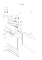
FIG. 1A illustrates an exploded perspective view of a battery pack according to an embodiment; -
FIG. 1B illustrates a perspective view of an assembled state of the battery pack ofFIG. 1A ; -
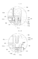
FIG. 1C illustrates a partial cross-sectional view taken along the line I - I ofFIG. 1B ; -
FIG. 1D illustrates an enlarged cross-sectional view ofFIG. 1C partially illustrating a peripheral portion of a screw; -
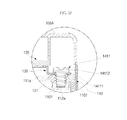
FIG. 1E illustrates a partial cross-sectional view ofFIG. 1D of a separated state of the screw; -
FIG. 1F illustrates a partial cross-sectional view of a comparative example of the screw ofFIG. 1E ; -
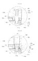
FIG. 2A illustrates a partial cross-sectional view of a battery pack according to another embodiment; -
FIG. 2B illustrates a partial cross-sectional view of an assembled state of the battery pack ofFIG. 2A ; -
FIG. 3A illustrates a partial cross-sectional view of a battery pack according to another embodiment; -
FIG. 3B illustrates a perspective view of an elastic supporting member ofFIG. 3A ; -
FIG. 4A illustrates a partial cross-sectional view of a battery pack according to another embodiment; -
FIG. 4B illustrates a perspective view of an elastic supporting member ofFIG. 4A ; -
FIG. 5A illustrates a partial cross-sectional view of a battery pack according to another embodiment; -
FIG. 5B illustrates a partial cross-sectional view of an assembled state of the battery pack ofFIG. 5A ; -
FIG. 5C illustrates a perspective view of an elastic supporting member ofFIG. 5A ; -
FIG. 6A illustrates a partial cross-sectional view of a battery pack according to another embodiment; and -
FIG. 6B illustrates a perspective view of an elastic supporting member ofFIG. 6A . - Example embodiments will now be described more fully hereinafter with reference to the accompanying drawings; however, they may be embodied in different forms and should not be construed as limited to the embodiments set forth herein.
- Rather, these embodiments are provided so that this disclosure will be thorough and complete, and will fully convey the scope of the invention to those skilled in the art.
- In the drawing figures, the dimensions of layers and regions may be exaggerated for clarity of illustration. It will also be understood that when a layer or element is referred to as being "on" another layer or substrate, it can be directly on the other layer or substrate, or intervening layers may also be present. Further, it will be understood that when a layer is referred to as being "under" another layer, it can be directly under, and one or more intervening layers may also be present. In addition, it will also be understood that when a layer is referred to as being "between" two layers, it can be the only layer between the two layers, or one or more intervening layers may also be present. Like reference numerals refer to like elements throughout.
- As used herein, the expressions "at least one," "one or more," and "and/or" are open-ended expressions that are both conjunctive and disjunctive in operation. For example, each of the expressions "at least one of A, B, and C," "at least one of A, B, or C," "one or more of A, B, and C," "one or more of A, B, or C" and "A, B, and/or C" includes the following meanings: A alone; B alone; C alone; both A and B together; both A and C together; both B and C together; and all three of A, B, and C together. Further, these expressions are open-ended, unless expressly designated to the contrary by their combination with the term "consisting of." For example, the expression "at least one of A, B, and C" may also include an nth member, where n is greater than 3, whereas the expression "at least one selected from the group consisting of A, B, and C" does not.
- As used herein, the expression "or" is not an "exclusive or" unless it is used in conjunction with the term "either." For example, the expression "A, B, or C" includes A alone; B alone; C alone; both A and B together; both A and C together; both B and C together; and all three of A, B, and C together, whereas the expression "either A, B, or C" means one of A alone, B alone, and C alone, and does not mean any of both A and B together; both A and C together; both B and C together; and all three of A, B, and C together.
- As used herein, the terms "a" and "an" are open terms that may be used in conjunction with singular items or with plural items.
- Referring to
FIGS. 1A through 1D , abattery pack 100 according to an embodiment may include acell 110, acircuit board 120, acoupling member 130,screws cover 150, and an elastic supportingmember 160. Thebattery pack 100 may further include alabel 170,elastic pads 180, and asupport case 190. - In an embodiment, the
screws first screw 141 and asecond screw 142. Couplinggrooves cell 110 may include afirst coupling groove 112a and asecond coupling groove 113a. Through-holes cover 150 may include a first through-hole 151a and a second through-hole 152a. Mountinggrooves holes groove 151b and asecond mounting groove 152b. - The
cell 110 may be a can-type battery having a positive electrode P+ and a negative electrode P-. Thecell 110 may be a bare cell. Thefirst coupling groove 112a and thesecond coupling groove 113a may be formed at each end, respectively, of a surface of an outer part of thecell 110. Thefirst screw 141 may be coupled to thefirst coupling groove 112a. Thesecond screw 142 may be coupled to thesecond coupling groove 113a. A screw thread may be formed in an inner circumferential surface of thefirst coupling groove 112a and thesecond coupling groove 113a by thefirst screw 141 and thesecond screw 142, respectively. The first andsecond coupling grooves burr prevention spaces FIG. 1E , the diameter d2 of theburr prevention space 112b may be greater by 10 to 30% than the diameter d1 of the general coupling groove area. The depth dt1, of the coupling groove, may be inversely proportional to the diameter d1 of the general coupling groove area. - The
cell 110 may be a can-type battery, in which an electrode assembly (not shown) formed by winding a positive electrode plate (not shown), a negative electrode plate (not shown), and a separator (not shown) may be sealed with a sealingassembly 111, formed of a metal material, e.g., aluminum. Thefirst coupling groove 112a and thesecond coupling groove 113a may be formed in the sealingassembly 111. The sealingassembly 111 may include a metal-type can 111b having an open end and acap plate 111a closing the open end. Anelectrode terminal 114, which may be insulated by aninsulator 114a, may be formed in the metal type can 111b and/or thecap plate 111a. InFIGS. 1A and1C , theelectrode terminal 114, which may be insulated by theinsulator 114a, may be inserted into thecap plate 111a. The positive electrode of thecell 110 may be electrically connected to the sealingassembly 111. The negative electrode of thecell 110 may be electrically connected to theelectrode terminal 114. Theelectrode terminal 114, which may be the negative electrode of thecell 110, and the sealingassembly 111, which may be the positive electrode of thecell 110, may have a different polarity. One pole of the electrode assembly may be electrically connected to the sealingassembly 111, and another pole thereof may be connected to theelectrode terminal 114. In an embodiment, theelectrode terminal 114 may be electrically connected to the negative electrode plate of the electrode assembly to form the negative electrode, and the sealingassembly 111 may be electrically connected to the positive electrode plate of the electrode assembly to form the positive electrode. - The
circuit board 120 may be electrically connected to thecell 110. Thecircuit board 120 may be a protective circuit board configured to control the charge/discharge of the cell and prevent overcharge/overdischarge of the cell, to protect the cell. The electrical connection between thecircuit board 120 and thecell 110 may be made by connecting the negative electrode of thecircuit board 120 to theelectrode terminal 114 by alead tab 120a, and by connecting the positive electrode of thecircuit board 120 to the sealing assembly, by thecoupling member 130. A positive temperature coefficient (PTC) device electrically connected between the negative electrode of thecircuit board 120 and theelectrode terminal 114 may block the electrical connection between the negative electrode of thecircuit board 120 and theelectrode terminal 114 when the temperature and/or the current gets too high. Thecircuit board 120 may include an insulatingsubstrate 121, a printed circuit pattern (not shown), aconducting pad 123, aprotection circuit unit 124, and a charging/dischargingterminal 125. Theconducting pad 123, theprotection circuit unit 124, and the charging/dischargingterminal 125 may be soldered to the printed circuit pattern formed on the insulatingsubstrate 121. Theprotection circuit unit 124 may include a passive element, e.g., a resistor, a condenser, etc., an active element, e.g., a field-effect transistor, a safety element such as the PTC device, and integrated circuits. Theprotection circuit unit 124 may charge or discharge thecell 110 when thecell 110 is charged/discharged, and may block a charging/discharging path of thecell 110 when thecell 110 is overheated or the current is too high, thereby preventing, e.g., lifetime degradation, overheating, explosion, etc., of thecell 110. - One end of the
coupling member 130 may be soldered and connected to thecircuit board 120, and another end thereof may be in contact with thecell 110. On a surface where thecoupling member 130 is in contact with thecell 110, acoupling hole 131 corresponding to thefirst coupling groove 112a of thecell 110 may be formed. Thecoupling member 130 may support thecircuit board 120, and may electrically connect the positive electrode of thecircuit board 120 and thecell 110. Thecoupling member 130 may include afirst region 132, asecond region 133, and athird region 134. Thefirst region 132 of thecoupling member 130 may be soldered and connected to thecircuit board 120. Thesecond region 133 of thecoupling member 130 may be bent to be substantially perpendicular to thefirst region 132. Thethird region 134 of thecoupling member 130, in which thecoupling hole 131 may be formed, may be bent in an opposite direction and substantially perpendicular to thesecond region 133. The second andthird regions coupling member 130 may be bent, so that thecircuit board 120 and a surface of thecell 110 are in parallel to each other. Thefirst coupling groove 112a formed in thecell 110 and thecoupling hole 131 of thecoupling member 130 may correspond to each other, so that thefirst screw 141 may be coupled substantially perpendicularly to thecell 110. Thecoupling member 130 may be formed of nickel or a nickel alloy, so that coupling and conductivity between thecoupling member 130 and theprotection circuit board 120 by soldering may be enhanced. - The
first screw 141 may be coupled to thefirst coupling groove 112a through thecoupling hole 131 of thecoupling member 130. Thesecond screw 142 may be coupled to thesecond coupling groove 113b. The first andsecond screws body parts head parts body parts second screws first coupling groove 112a and thesecond coupling groove 113a, respectively, forming a screw thread thereon. Thehead parts second screws body parts body parts head parts second screws coupling grooves - The
cover 150 may surround thecircuit board 120. Thefirst mounting groove 151b and the second mountinggroove 152b may be formed in thecover 150. The first through-hole 151a and the second through-hole 152a may pass through the centers of the first and second mountinggrooves body part 141a of thefirst screw 141 may pass through the first through-hole 151a. Thehead part 141b of thefirst screw 141 may be tightly coupled to the first mountinggroove 151b. Thebody part 142a of thesecond screw 142 may pass through the second through-hole 152a. Thehead part 142b of thesecond screw 142 may be tightly coupled to the second mountinggroove 152b. Thecover 150 may be a plastic case formed by injection molding a resin material, e.g., polycarbonate. Thecover 150 may protect thecircuit board 120 against an external force and prevent a short circuit of thecircuit board 120.Ribs 151 may be formed inside thecover 150 and support a top surface of thecircuit board 120 so that thecircuit board 120 may be tightly coupled to thecell 110. After thecover 150 is coupled to thecircuit board 120, thecover 150 and thecell 110 may be surrounded by thelabel 170. The charging/dischargingterminal 125 may be exposed to the outside by a charging/discharging terminal hole formed in thecover 150. Sealingmembers 154 may be inserted into the first and second mountinggrooves members 154 may prevent penetration of impurities from the outside by sealing the first and second mountinggrooves - The elastic supporting
member 160 may be disposed, and provide support, between thefirst screw 141 and thecoupling member 130. The elastic supportingmember 160 may be formed of a metal material in the shape of a cylinder type washer. The elastic supportingmember 160 may be inserted into the first through-hole 151a while surrounding thebody part 141a of thefirst screw 141, to lend support between a bottom surface of thehead part 141b and a top surface of thecoupling member 130. The elastic supportingmember 160 may protrude higher, by a specific height 160ET, than the height of the first through-hole 151a, as illustrated inFIG. 1E . The elastic supportingmember 160 may protrude upward, by the specific height 160ET, from a bottom surface of the first mountinggroove 151b. - The
label 170 may surround thecell 110 and thecover 150. Thelabel 170 may attach to thecell 110 and thecover 150 by an adhesive. Information, e.g., the capacity and serial number of thebattery pack 100, may be printed on an outer surface of thelabel 170. - The
elastic pad 180 may support thecircuit board 120 and thecell 110. Theelastic pad 180 may be formed of, e.g., silicon, rubber, and/or a foam tape, including a porous material. Theelastic pad 180 may be formed on both sides of the battery pack between thecell 110 and thecircuit board 120. - The
support case 190 may surround corner parts of thecell 110, thereby preventing the corner parts of thecell 110 from being deformed when an external force is applied. A double-side tape 171 may be formed between thesupport case 190 and thecell 110 to couple thesupport case 190 to thecell 110. An outer surface of thesupport case 190 may be surrounded by thelabel 170, so that the coupling between thesupport case 190 and thecell 110 may be enhanced. - Hereinafter, the operation and advantages of a
battery pack 100 according to an embodiment will be described in detail. - The
battery pack 100 may prevent the contact resistance between thecoupling member 130 and thecell 110 from being increased because the elastic supportingmember 160 may provide support between thefirst screw 141 and thecoupling member 130. More specifically, the elastic supportingmember 160 may enhance coupling when thefirst screw 141 is coupled to thefirst coupling groove 112a, and may prevent an increase in the contact resistance between thecoupling member 130 and thecell 110 due to an external force. The elastic supportingmember 160 may also function to prevent thefirst screw 141 from coming loose due to an external force. The elastic supportingmember 160 may be deformed outward from a central circumference as thefirst screw 141 is screw-coupled to thefirst coupling groove 112a. The elastic supportingmember 160 may push against the first through-hole 151a formed in thecover 150. Accordingly, the elastic supportingmember 160 may be tightly inserted into thecover 150 to prevent movement of thecover 150. Movement of thecoupling member 130 may also prevented, so that it may be possible to prevent the contact resistance between thecoupling member 130 and thecell 110 from being increased. - As illustrated in
FIG. 1E , the elastic supportingmember 160 may protrude higher, by the specific height 160ET, than the height of the first through-hole 151a. The elastic supportingmember 160 may protrude upward, by the specific height 160ET, from the bottom surface of the first mountinggroove 151b, which is a boundary between the first through-hole 151a and the first mountinggroove 151b. Thus, thehead part 141b of thefirst screw 141 may not be in contact with the first mountinggroove 151b, and the elastic supportingmember 160 may be curved outward in an amount relative to the specific height 160ET. Therefore, thefirst screw 141 may apply pressure to the elastic supportingmember 160 when coupling to thefirst coupling groove 112a, so that an outer circumferential part of the elastic supportingmember 160 may be curved outward to push against an inner circumferential part of the first mountinggroove 151b. Accordingly, the movement of thecover 150 may be prevented by the curved deformation of the elastic supportingmember 160. - One side of the
coupling member 130 may be soldered to thecircuit board 120. The other side of thecoupling member 130 may be bent to be in contact with a surface of thecell 110. Thecoupling member 130 may include afirst region 132, asecond region 133 bent substantially perpendicularly to the first region, and athird region 134 bent substantially perpendicularly to thesecond region 133 in a direction away from thefirst region 132. Theaforementioned regions coupling member 130 to support thecircuit board 120, to be screw-coupled to thecell 110, and to increase the contact area between thefirst screw 141 and thecell 110. Accordingly, the contact area between thecoupling member 130 and thecell 110 may be increased, thereby lowering contact resistance. - The first and
second screws second coupling grooves circuit board 120 is not distorted. Since the coupling strength between thefirst screw 141 and thecoupling member 130 may be greater than in a conventional battery pack, the contact resistance between thecoupling member 130 and thecell 110 may not be increased due to an external force. - In the
first screw 141, thehead part 141b may apply pressure to a top surface of the elastic supportingmember 160 while thebody part 141a is inserted through the elastic supportingmember 160. - The
coupling member 130 may be coupled tightly to thecell 110 by the elastic supportingmember 160, and the contact resistance between thecoupling member 130 andcell 110 may not increase due to an external force. - In the
cover 150, the top surface of thecircuit board 120 may be supported by theribs 151 formed inside thecover 150 so that thecoupling member 130 may be tightly coupled to thecell 110. Accordingly, it may be possible to prevent the contact resistance between thecoupling member 130 and thecell 110 from being increased when an external force is applied by increasing the contact force between thecoupling member 130 and thecell 110. - The
cover 150 may be tightly coupled to thecoupling member 130 so that thecoupling member 130 may in turn be tightly coupled to thecell 110. Accordingly, the contact force between thecoupling member 130 and thecell 110 may increase, thereby preventing contact resistance from being increased when an external force is applied. - Since the
label 170 may allow thecell 110 and thecover 150 to be coupled to each other, it may be possible to prevent thecoupling member 130, thescrews member 160 from being moved due to an external force by preventing movement of thecover 150. Accordingly, thelabel 170 may prevent the contact resistance between thecoupling member 130 and thecell 110 from being increased. - Because the
elastic pad 180 may support thecoupling member 130 and thecell 110 and absorb an impact applied from the outside, it may be possible to prevent the contact resistance between thecoupling member 130 and thecell 110 from being increased. Theelastic pad 180 may be mounted on thecell 110 to provide an elastic force for pushing against thecircuit board 120. Accordingly, thecoupling member 130 soldered to thecircuit board 120 may push against the elastic supportingmember 160 upwardly to enhance coupling. Therefore, loosening of the first andsecond screws coupling member 130 and thecell 110 may not be increased due to an external force. - When the
coupling member 130 is coupled to thefirst coupling groove 112a by thefirst screw 141, thebattery pack 100 may not increase the contact resistance between thecoupling member 130 and thecell 110, even when an external force is applied to thebattery pack 100. Referring to the conventional coupling system illustrated inFIG. 1F , a screw 141f may be coupled to thefirst coupling groove 112a, as thefirst coupling groove 112a is formed in thecell 110. As illustrated inFIG. 1F , when thecoupling member 130 is coupled to thecell 110 by the screw 141f, aburr 110f may be generated. When a body part 141f1 of the screw 141f is screw-coupled to thefirst coupling groove 112a, theburr 110f is formed by pushing a top surface of thefirst coupling groove 112a with the body part 141f1. Then, theburr 110f protrudes from the top surface of thefirst coupling groove 112a and below a head part 141f2 of the screw 141f. When the screw 141f is coupled to thecoupling groove 112a, thecoupling member 130 between the head part 141f2 of the screw 141f and thefirst coupling groove 112a of thecell 110 may be tightly coupled to theburr 110f, which may reduce coupling area. When an external impact is applied to thecell 110, thecoupling member 130 may move up and down, which may further reduce the coupling area between theburr 110f and thecoupling member 130. Therefore, contact resistance between thecell 110 and thecoupling member 130 may increase. - In an embodiment, the
first coupling groove 112a may include a firstburr prevention space 112b and a general coupling groove area. The firstburr prevention space 112b may have a diameter greater than that of the general coupling groove area of thefirst coupling groove 112a. The firstburr prevention space 112b may be formed in an opening part of thefirst coupling groove 112a in which a burr would be formed, in order to prevent aburr 110f from forming, as illustrated inFIG. 1E . Therefore, since the area where the burr would be formed may be removed, if an external impact is applied to thecell 110 and thecircuit board 120, contact resistance between thecell 110 and thecoupling member 130 may not increase, thereby enhancing reliability of thebattery pack 110. - Since the diameter d1 of the general coupling groove area of the
first coupling groove 112a may be inversely proportional to the depth dt1 of thefirst coupling groove 112a, thebattery pack 100 may enhance the coupling strength between thefirst screw 141 and thecell 110. More specifically, when thescrew 141 is screw-coupled to thefirst coupling groove 112a by passing through thecoupling hole 131 of thecoupling member 130, the diameter d1 of a general coupling groove area of thefirst coupling groove 112a may be small, which may increase the coupling strength between thefirst screw 141 and thefirst coupling groove 112a. - Since the diameter d2 of the first
burr prevention space 112b of thefirst coupling groove 112a may be greater than the diameter d1 of the general coupling groove area, a burr may not be generated. The firstburr prevention space 112b having the diameter d2, greater than the diameter d1 of the general coupling groove area of thefirst coupling groove 112a, may be formed in an opening part of thefirst coupling groove 112a to prevent generation of a burr. Therefore, the coupling between thefirst screw 141 and thefirst coupling groove 112a may be enhanced, and the generation of the burr may be prevented, so that thebattery pack 100 may prevent contact resistance from being increased, even when an external force is applied to thebattery pack 100. - As illustrated in
FIG. 1E , the diameter d2 of theburr prevention space 112b of thefirst coupling groove 112a may be about 10 to about 30% greater than the diameter d1 of the general coupling groove area of thefirst coupling groove 112a. Maintaining the diameter d2 of theburr prevention space 112b at about 10% greater than the diameter d1 of thefirst coupling groove 112a or more may help ensure that a burr is not generated around thefirst coupling groove 112a. Maintaining the diameter d2 of theburr prevention space 112b at about 30% greater than the diameter d1 of the general coupling groove area of thefirst coupling groove 112a or less may help ensure that the contact area of thecoupling member 130 and thecell 110 is not decreased, nor contact resistance between thecoupling member 130 and thecell 110 increased. Accordingly, the diameter d2 of theburr prevention space 112b may be formed to be about 10 to about 30% greater than the diameter d1 of general coupling groove area of thefirst coupling groove 112a, so that the contact resistance between thecoupling member 130 and thecell 110 may be maintained to a certain degree, and the generation of the burr formed around thefirst coupling groove 112a may be prevented, thereby reducing contact resistance. - As illustrated in
FIGS. 2A and 2B , thebattery pack 200 of an embodiment may include acell 110, acircuit board 120, acoupling member 130, first andsecond screws cover 150, and an elastic supportingmember 260. Thebattery pack 200 of an embodiment may further include alabel 170, anelastic pad 180, and asupport case 190, which may be described with reference toFIG. 1A . In an embodiment, the elastic supportingmember 260 will now be described. - In the
battery pack 200 of an embodiment, the elastic supportingmember 260 may be formed in the shape of a cylinder-type washer. A top surface of the elastic supportingmember 260 may be formed to have the same height as, and flush with, a first mountinggroove 151b of thecover 150. Ahead part 141b of thefirst screw 141 may be tightly coupled to a bottom surface of the first mountinggroove 151b and the top surface of the elastic supportingmember 260. - In the
battery pack 200 of an embodiment, thehead part 141b of thefirst screw 141 may be simultaneously tightly coupled to the top surface of the elastic supportingmember 260 and the bottom surface of the first mountinggroove 151b. Accordingly, thehead part 141b of thefirst screw 141 may be coupled to the first mountinggroove 151b of thecover 150, thereby preventing movement of thecover 150, and the elastic supportingmember 260 may tightly couple thecoupling member 130 to thecell 110, thereby preventing an increase in contact resistance. - As illustrated in
FIG. 3A , thebattery pack 300 of an embodiment may include acell 110, acircuit board 120, acoupling member 130, afirst screw 141, acover 150, and an elastic supportingmember 360. Thebattery pack 300 of an embodiment may further include alabel 170, anelastic pad 180, and asupport case 190, which may be described with reference toFIG. 1A . In an embodiment, the elastic supportingmember 360 will now be described. - In the
battery pack 300 of an embodiment, the elastic supportingmember 360 may include a combiningpart 361 and ahoop part 362. - The combining
part 361 may be formed in a cylinder shape and inserted into a first through-hole 151a of thecover 150. A bottom surface of the combiningpart 361 may be tightly coupled to thecoupling member 130. Acenter hole 361a through which abody part 141a of thefirst screw 141, may pass may be formed at the center of the combiningpart 361. - The
hoop part 362 may be connected to the combiningpart 361, protrude from a circumferential surface of the combiningpart 361, and have a greater diameter than that of the combiningpart 361. A bottom surface of thehoop part 362 may tightly couple to a first mountinggroove 151b of thecover 150, and a top surface of thehoop part 362 may tightly couple to a bottom surface of ahead part 141b of thefirst screw 141. - In the
battery pack 300 according to an embodiment, thehoop part 362 of the elastic supportingmember 360 may tightly couple to the first mountinggroove 151b of thecover 150, and the combiningpart 361 may be inserted into a first through-hole 151a of thecover 150 to be stably mounted on thecover 150. Therefore, thehead part 141b of thefirst screw 141 may tightly couple to thehoop part 362 of the elastic supportingmember 360. Thecoupling member 130 may tightly couple to thecell 110 due to the pressure applied by the bottom surface of the combiningpart 361, so that contact resistance may not be increased due to an external force. Because thehead part 141b of thefirst screw 141 may tightly couple to thehoop part 362 of the elastic supportingmember 360, the first mountinggroove 151b of thecover 150 may also tightly couple thereto, thereby preventing movement of thecover 150. - As illustrated in
FIG. 4A , thebattery pack 400 of an embodiment may include acell 110, acircuit board 120, acoupling member 130, afirst screw 141, acover 450, and an elastic supportingmember 460. Thebattery pack 400 of an embodiment may further include alabel 170, anelastic pad 180, and asupport case 190, which may be described with reference toFIG. 1A . In an embodiment, thecover 450 and the elastic supportingmember 460 will now be described. - The
cover 450 may be formed in a shape similar to the cover of the aforementioned embodiment and formed of the same material as the cover of the aforementioned embodiment. However, thecover 450 of an embodiment may be a cover providing aspace 457 into which ahoop part 462 of the elastic supportingmember 460 may be inserted at a lower portion of a first through-hole 151a. - The elastic supporting
member 460 may include a combiningpart 461 and ahoop part 462. - The combining
part 461 may be formed in a cylinder shape and inserted into the first through-hole 151a of thecover 450. Acenter hole 461a may be formed at the center of the combiningpart 461. A top surface of the combiningpart 461 may tightly couple to a bottom surface of ahead part 141b of thefirst screw 141. - The
hoop part 462 may be connected to the combiningpart 461, protrude from a circumferential surface of the combiningpart 461, and have a greater diameter than that of the combiningpart 461. Thehoop part 462 of the elastic supportingmember 460 ofFIG. 4B may be formed in, e.g., a circular shape to protrude from the combiningpart 461. Thehoop part 462, however, may have any suitable shape protrude from a circumferential surface of the combiningpart 461. - In the
battery pack 400 of an embodiment, thehead part 141b of thefirst screw 141 may tightly couple to a first mountinggroove 151b of thecover 450 and apply pressure to the top surface of the combiningpart 461, so that the combiningpart 461 may tightly couple to thecoupling member 130. Because thehoop part 462 may have a greater diameter than that of the combiningpart 461, increasing the contact area of the elastic supportingmember 460 and thecoupling member 130, thehoop part 462 may strongly couple to thecoupling member 130. Accordingly, thecoupling member 130 may strongly couple to thecell 110, so that thebattery pack 400 of an embodiment may prevent an increase in contact resistance due to an external force. Because thehead part 141b of thefirst screw 141 may apply pressure to the top surface of the combiningpart 461, and may tightly couple to the first mountinggroove 151b of thecover 450, preventing movement of thecover 450, thecover 450 and thecell 110 may be integrally formed. - As illustrated in
FIGS. 5A and 5B , thebattery pack 500 of an embodiment may include acell 110, acircuit board 120, acoupling member 130, afirst screw 141, acover 150, and an elastic supportingmember 560. Thebattery pack 500 of an embodiment may further include alabel 170, anelastic pad 180, and asupport case 190, which may be described with reference toFIG. 1A . In an embodiment, the elastic supportingmember 560 will now be described. - In the
battery pack 500 of an embodiment, the elastic supportingmember 560 may be formed in the shape of a cylinder having ahole 561 formed at the center thereof. As illustrated inFIG. 5C , a bendingpart 562 may be formed at an outer circumferential surface of the elastic supportingmember 560. The bendingpart 562 may protrude around the outer circumferential surface of the elastic supportingmember 560 to surround the center part of the outer circumferential surface of the elastic supportingmember 560. As illustrated inFIG. 5B , the elastic supportingmember 560 may be inserted into a first through-hole 151a of thecover 150 and then couple tightly to thecoupling member 130 and ahead part 141b of thefirst screw 141. As thefirst screw 141 is screw-coupled to afirst coupling groove 112a, pressure may be applied to the elastic supportingmember 560 to tightly couple it to thecoupling member 130. The bendingpart 562 of the elastic supportingmember 560 may protrude outward from the outer circumferential surface of the elastic supportingmember 560 and bend toward an upper part and a center part of the elastic supportingmember 560. Since the elastic supportingmember 560 may generate an elastic force for pushing against thehead part 141b of thefirst screw 141 and thecoupling member 130, loosening of thefirst screw 141 may be prevented. Thecoupling member 130 may be more tightly coupled to thecell 110, thereby preventing an increase in contact resistance due to an external force. Thehead part 141b of thefirst screw 141 may tightly couple to the first mountinggroove 151b of thecover 150 to prevent movement of thecover 150, thereby forming an integrated battery pack. - As shown in
FIG. 6A , thebattery pack 600 of an embodiment may include acell 110, acircuit board 120, acoupling member 130, afirst screw 141, acover 650, and an elastic supportingmember 660. Thebattery pack 600 of an embodiment may further include alabel 170, anelastic pad 180, and asupport case 190, which may be described with reference toFIG. 1A . In and, thecover 650 and the elastic supportingmember 660 will now be described. - The
cover 650 may be formed into a structure similar to the cover of the aforementioned embodiment described with reference toFIG. 1A . However, a mounting groove formed at an upper part of a first through-hole 151a of the aforementioned embodiment may not be formed, and a space in which ahoop part 662 of the elastic supportingmember 660 may be coupled to thecover 650 may be further formed. - The elastic supporting
member 660 may include a combiningpart 661 and thehoop part 662. - The combining
part 661 may be formed in a cylinder shape. Acenter hole 661a may be formed at the center of the combiningpart 661 so that abody part 141a of thefirst screw 141 may pass therethrough. The combiningpart 661 of the elastic supportingmember 660 may be coupled to the first through-hole 151a by bonding or by inserting the elastic supportingmember 660 into the first through-hole 151a while melting a surface of the first through-hole 151a of thecover 650. Alternatively, the combiningpart 661 may be coupled to the first through-hole 151a by being tightly inserted into the first through-hole 151a. - The
hoop part 662 may be connected to an end of the combiningpart 661, protrude from a circumferential surface of the combiningpart 661, and have a greater diameter than that of the combiningpart 661. Thehoop part 662 may tightly couple to thecoupling member 130. - In the
battery pack 600 of an embodiment, the combiningpart 661 of the elastic supportingmember 660, while being integrally formed with the first through-hole 151a, may apply pressure downward from ahead part 141b of thefirst screw 141. Therefore, thehoop part 662 may more tightly couple to thecoupling member 130, thereby increasing the coupling strength between the elastic supportingmember 660 and thecoupling member 130, preventing contact resistance between thecoupling member 130 and thecell 110 from being increased due to an external force. Thebattery pack 600 of an embodiment may prevent movement of thecover 650 by integrally forming the elastic supportingmember 660 with thecover 650. - As described above, according to embodiments, a battery pack may not increase contact resistance between a cell and a circuit board when an external force is applied to the battery pack.
- Further, a battery pack may be easier to assemble by integrally forming a cell, a circuit board, and a cover so that the contact resistance between the cell and the protection circuit board is not increased due to an external force.
- The battery pack of an embodiment may be used in portable electronic devices, e.g., cellular phones, notebook computers, camcorders, and the like.
- Exemplary embodiments of the present invention have been disclosed herein, and although specific terms are employed, they are used and are to be interpreted in a generic and descriptive sense only and not for purpose of limitation. Accordingly, it will be understood by those of ordinary skill in the art that various changes in form and details may be made without departing from the scope of the present invention as set forth in the following claims.
Claims (15)
- A battery pack, comprising:a cell (110) having a surface including a coupling groove (112a);a circuit board (120) electrically connected to the cell (110);a coupling member (130) coupled to the cell (110), having one end coupled to the circuit board (120) and another end having a coupling hole (131) corresponding to the one coupling groove (112a);a cover (150) surrounding the circuit board (120), mounted on one surface of the cell (110), and having a through-hole (151a);a screw (141) coupled to the coupling groove (112a) through the through-hole (151a); andan elastic supporting member (160, 260, 360, 460, 560) disposed between a head part of the screw (141) and the coupling member (130).
- The battery pack as claimed in claim 1, wherein the cover (150) includes a mounting groove (151b), the through-hole (151a) passes through a center of the mounting groove (151b), and the screw (141) is mounted in the mounting groove (151b) through the through hole (151a).
- The battery pack as claimed in claim 1 or 2, wherein the elastic supporting member (160, 260, 360, 460, 560) is in the shape of a cylinder-type washer, and a sidewall of the washer has a height that is greater than its thickness.
- The battery pack as claimed in any one of the preceding claims, wherein the elastic supporting member (160, 360) is in the through-hole, and one end of the elastic supporting member protrudes higher than a contact part of the mounting groove (151b).
- The battery pack as claimed in any one of claims 1 to 3, wherein one end of the elastic supporting member (260, 460) is flush with a contact part of the mounting groove (151b).
- The battery pack as claimed in any one of the preceding claims, wherein the elastic supporting member (360, 460, 660) includes:a combining part (361, 461, 661) having a center hole (361a, 461a, 661a) in a center of the elastic supporting member (360, 460, 660); anda hoop part (262, 462, 662) connected to the combining part (361, 461, 661), protruding from a circumferential surface of the combining part (361, 461, 661), and having a diameter greater than a diameter of the combining part (361, 461, 661).
- The battery pack as claimed in claim 6 when dependent on claim 2, wherein:the combining part (361) is mounted in the through-hole (151a) of the cover (151), and is coupled to the coupling member (130); anda bottom surface of the hoop part (262) is coupled to the mounting groove (151b) of the cover (151) and a top surface of the hoop part (361) is coupled to the screw (141).
- The battery pack as claimed in claim 2, wherein the elastic supporting member (560) has a cylinder shape, a sidewall of the washer has a height that is greater than its thickness, and includes a bending part (562) that protrudes outward at an outer circumferential surface of the elastic supporting member (560).
- The battery pack as claimed in any one of the preceding claims, wherein a diameter of the coupling groove (112a) in the cell (110) is inversely proportional to a depth of the coupling groove (112a).
- The battery pack as claimed in anyone of the preceding claims, wherein the coupling groove (112a) includes a burr prevention space (112b) adjacent to the coupling member (130), the burr prevention space (112b) having a diameter d2, and a main coupling groove area, the main coupling groove area having a diameter d1, and the diameter of the burr prevention space d2 is greater than the diameter of the main coupling groove area d1.
- The battery pack as claimed in claim 10, wherein the diameter d2 of the burr prevention space (112b) is about 10 to about 30 % greater than the diameter d1 of the main coupling groove area.
- The battery pack as claimed inany one of the preceding claims, wherein the cover (150) is coupled to the coupling member (130) and the coupling member (130) is in contact with the cell (110).
- The battery pack as claimed in any one of the preceding claims, wherein the coupling member (130) includes:a first region (132) soldered to the circuit board (120);a second region (133) bent substantially perpendicular in the first region (132); anda third region (133) including the coupling hole (131), and bent to be substantially perpendicular to the second region (133) and away from the first region (132).
- The battery pack as claimed in claim 1, wherein the elastic supporting member is coupled to the through-hole through at least one of thermally inserting, tightly inserting, bonding, and screw coupling.
- The battery pack as claimed in claim 1, wherein the elastic supporting member includes:a combining part having a center hole in a center of the elastic supporting member; anda hoop part connected to the combining part, protruding from a circumferential surface of the combining part, and having a diameter greater than a diameter of the combining part,wherein the combining part is coupled to the coupling hole, and the hoop part is coupled to the coupling member.
Applications Claiming Priority (1)
| Application Number | Priority Date | Filing Date | Title |
|---|---|---|---|
| KR1020080003999A KR100947973B1 (en) | 2008-01-14 | 2008-01-14 | Battery pack |
Publications (2)
| Publication Number | Publication Date |
|---|---|
| EP2079126A1 true EP2079126A1 (en) | 2009-07-15 |
| EP2079126B1 EP2079126B1 (en) | 2011-03-23 |
Family
ID=40469813
Family Applications (1)
| Application Number | Title | Priority Date | Filing Date |
|---|---|---|---|
| EP09150392A Ceased EP2079126B1 (en) | 2008-01-14 | 2009-01-12 | Impact Resistant Battery Pack |
Country Status (6)
| Country | Link |
|---|---|
| US (1) | US8597822B2 (en) |
| EP (1) | EP2079126B1 (en) |
| JP (1) | JP5193017B2 (en) |
| KR (1) | KR100947973B1 (en) |
| CN (1) | CN101488563B (en) |
| DE (1) | DE602009000920D1 (en) |
Cited By (3)
| Publication number | Priority date | Publication date | Assignee | Title |
|---|---|---|---|---|
| EP2423997A1 (en) * | 2010-08-27 | 2012-02-29 | Samsung SDI Co., Ltd. | Battery pack comprising a cover with a resilient material |
| WO2012167022A1 (en) * | 2011-06-03 | 2012-12-06 | Johnson Controls Technology Llc | Electrochemical cells with improved heat collection and transfer systems |
| CN111106304A (en) * | 2018-10-30 | 2020-05-05 | 宁德时代新能源科技股份有限公司 | Secondary battery |
Families Citing this family (26)
| Publication number | Priority date | Publication date | Assignee | Title |
|---|---|---|---|---|
| US20100055560A1 (en) * | 2008-08-29 | 2010-03-04 | Youngcheol Jang | Secondary battery |
| KR101036030B1 (en) | 2008-12-01 | 2011-05-19 | 삼성에스디아이 주식회사 | Secondary battery |
| KR101023898B1 (en) | 2008-12-02 | 2011-03-22 | 삼성에스디아이 주식회사 | Secondary battery |
| KR101040975B1 (en) * | 2009-02-26 | 2011-06-16 | 주식회사 엘지화학 | New rechargeable battery pack |
| KR101030906B1 (en) * | 2009-06-18 | 2011-04-22 | 삼성에스디아이 주식회사 | Secondary battery |
| KR101419990B1 (en) | 2009-07-21 | 2014-07-15 | 아사히 가라스 가부시키가이샤 | Hanger assembly and apparatus for producing float plate glass |
| KR101075356B1 (en) * | 2009-09-09 | 2011-10-19 | 삼성에스디아이 주식회사 | Battery pack |
| US9048477B2 (en) | 2009-09-09 | 2015-06-02 | Samsung Sdi Co., Ltd. | Battery pack |
| KR101084823B1 (en) | 2009-09-29 | 2011-11-21 | 삼성에스디아이 주식회사 | Secondary battery |
| KR101082135B1 (en) | 2009-11-24 | 2011-11-09 | 삼성에스디아이 주식회사 | Battery pack |
| KR101093935B1 (en) * | 2009-11-27 | 2011-12-13 | 삼성에스디아이 주식회사 | Battery pack |
| KR101127613B1 (en) * | 2010-05-13 | 2012-03-22 | 삼성에스디아이 주식회사 | Battery Pack |
| KR101113554B1 (en) | 2010-07-29 | 2012-02-24 | 삼성에스디아이 주식회사 | Secondary battery |
| KR101166024B1 (en) | 2010-08-04 | 2012-07-19 | 삼성에스디아이 주식회사 | External terminal assembly and battery pack using the same |
| US20120171556A1 (en) * | 2010-12-29 | 2012-07-05 | Jongpil Kim | Secondary battery |
| USD659694S1 (en) * | 2011-01-04 | 2012-05-15 | Sony Corporation | Memory unit |
| US8790823B2 (en) | 2011-02-08 | 2014-07-29 | Samsung Sdi Co., Ltd. | Battery unit and battery pack having less resistance and improved contacts |
| US20150228944A1 (en) * | 2012-05-10 | 2015-08-13 | Htc Corporation | Fixing tube and electronic apparatus |
| KR20140101164A (en) * | 2013-02-08 | 2014-08-19 | 삼성에스디아이 주식회사 | Battery Pack |
| KR20140102927A (en) * | 2013-02-15 | 2014-08-25 | 삼성에스디아이 주식회사 | Battery pack |
| KR102261183B1 (en) * | 2017-11-22 | 2021-06-07 | 주식회사 엘지에너지솔루션 | Cable type battery |
| JP7310096B2 (en) * | 2018-04-10 | 2023-07-19 | ソニーグループ株式会社 | Battery packs and electronic devices |
| CN110729507B (en) * | 2018-07-17 | 2021-11-09 | 宁德时代新能源科技股份有限公司 | Secondary battery and method for manufacturing secondary battery |
| CN210668432U (en) * | 2019-10-10 | 2020-06-02 | 宁德新能源科技有限公司 | Shell and battery with same |
| US20240274949A1 (en) * | 2021-07-19 | 2024-08-15 | Lg Energy Solution, Ltd. | Cell assembly |
| CN220934324U (en) * | 2024-02-22 | 2024-05-10 | 宁德时代新能源科技股份有限公司 | Battery, electric equipment and energy storage equipment |
Citations (6)
| Publication number | Priority date | Publication date | Assignee | Title |
|---|---|---|---|---|
| JP2001250525A (en) | 2000-03-07 | 2001-09-14 | Japan Storage Battery Co Ltd | Fixed structure of battery-driven electronic equipment |
| JP2006004783A (en) | 2004-06-17 | 2006-01-05 | Furukawa Electric Co Ltd:The | Protection module and its assembly method |
| JP2006147123A (en) | 2004-11-15 | 2006-06-08 | Hynix Semiconductor Inc | Refresh method for memory device |
| JP2006147193A (en) * | 2004-11-16 | 2006-06-08 | Sanyo Electric Co Ltd | Pack battery |
| JP2007035520A (en) | 2005-07-28 | 2007-02-08 | Sanyo Electric Co Ltd | Vehicular power supply device |
| EP1814189A1 (en) * | 2004-10-27 | 2007-08-01 | Matsushita Electric Industrial Co., Ltd. | Battery pack |
Family Cites Families (7)
| Publication number | Priority date | Publication date | Assignee | Title |
|---|---|---|---|---|
| JP3825738B2 (en) | 2002-10-31 | 2006-09-27 | 三洋電機株式会社 | Pack battery and manufacturing method thereof |
| JP4488728B2 (en) | 2003-12-19 | 2010-06-23 | 三洋電機株式会社 | Thin battery pack |
| JP4488730B2 (en) | 2003-12-22 | 2010-06-23 | 三洋電機株式会社 | Thin battery pack |
| JP4778699B2 (en) * | 2004-10-27 | 2011-09-21 | パナソニック株式会社 | Battery pack |
| JP4837278B2 (en) * | 2004-12-02 | 2011-12-14 | パナソニック株式会社 | Battery pack |
| US20070017720A1 (en) * | 2005-07-25 | 2007-01-25 | Kazuhiro Fujii | Battery device of vehicle power supply |
| JP2007273375A (en) * | 2006-03-31 | 2007-10-18 | Brother Ind Ltd | Connection terminal mounting structure and mobile communication terminal |
-
2008
- 2008-01-14 KR KR1020080003999A patent/KR100947973B1/en not_active Expired - Fee Related
- 2008-12-22 JP JP2008325856A patent/JP5193017B2/en not_active Expired - Fee Related
-
2009
- 2009-01-12 US US12/318,896 patent/US8597822B2/en not_active Expired - Fee Related
- 2009-01-12 EP EP09150392A patent/EP2079126B1/en not_active Ceased
- 2009-01-12 DE DE602009000920T patent/DE602009000920D1/en active Active
- 2009-01-13 CN CN2009100031028A patent/CN101488563B/en not_active Expired - Fee Related
Patent Citations (6)
| Publication number | Priority date | Publication date | Assignee | Title |
|---|---|---|---|---|
| JP2001250525A (en) | 2000-03-07 | 2001-09-14 | Japan Storage Battery Co Ltd | Fixed structure of battery-driven electronic equipment |
| JP2006004783A (en) | 2004-06-17 | 2006-01-05 | Furukawa Electric Co Ltd:The | Protection module and its assembly method |
| EP1814189A1 (en) * | 2004-10-27 | 2007-08-01 | Matsushita Electric Industrial Co., Ltd. | Battery pack |
| JP2006147123A (en) | 2004-11-15 | 2006-06-08 | Hynix Semiconductor Inc | Refresh method for memory device |
| JP2006147193A (en) * | 2004-11-16 | 2006-06-08 | Sanyo Electric Co Ltd | Pack battery |
| JP2007035520A (en) | 2005-07-28 | 2007-02-08 | Sanyo Electric Co Ltd | Vehicular power supply device |
Cited By (8)
| Publication number | Priority date | Publication date | Assignee | Title |
|---|---|---|---|---|
| EP2423997A1 (en) * | 2010-08-27 | 2012-02-29 | Samsung SDI Co., Ltd. | Battery pack comprising a cover with a resilient material |
| US9818990B2 (en) | 2010-08-27 | 2017-11-14 | Samsung Sdi Co., Ltd. | Battery pack with shock absorber |
| WO2012167022A1 (en) * | 2011-06-03 | 2012-12-06 | Johnson Controls Technology Llc | Electrochemical cells with improved heat collection and transfer systems |
| US8906532B2 (en) | 2011-06-03 | 2014-12-09 | Johnson Controls Technology Llc | Electrochemical cells with improved heat collection and transfer systems |
| CN111106304A (en) * | 2018-10-30 | 2020-05-05 | 宁德时代新能源科技股份有限公司 | Secondary battery |
| CN111106304B (en) * | 2018-10-30 | 2021-02-26 | 宁德时代新能源科技股份有限公司 | Secondary battery |
| CN111106304B9 (en) * | 2018-10-30 | 2021-06-11 | 宁德时代新能源科技股份有限公司 | Secondary battery |
| US12142795B2 (en) | 2018-10-30 | 2024-11-12 | Contemporary Amperex Technology (Hong Kong) Limited | Top pressing plate, secondary battery and method for manufacturing secondary battery |
Also Published As
| Publication number | Publication date |
|---|---|
| DE602009000920D1 (en) | 2011-05-05 |
| KR100947973B1 (en) | 2010-03-15 |
| EP2079126B1 (en) | 2011-03-23 |
| CN101488563A (en) | 2009-07-22 |
| KR20090078181A (en) | 2009-07-17 |
| US8597822B2 (en) | 2013-12-03 |
| JP2009170417A (en) | 2009-07-30 |
| US20090186268A1 (en) | 2009-07-23 |
| JP5193017B2 (en) | 2013-05-08 |
| CN101488563B (en) | 2012-05-23 |
Similar Documents
| Publication | Publication Date | Title |
|---|---|---|
| EP2079126B1 (en) | Impact Resistant Battery Pack | |
| US8623531B2 (en) | Battery pack | |
| US8277963B2 (en) | Battery pack | |
| US8956749B2 (en) | Battery pack | |
| EP2166595B1 (en) | Secondary battery | |
| JP5059731B2 (en) | Battery pack | |
| US7981540B2 (en) | Rechargeable battery | |
| CN101599551B (en) | Battery pack | |
| KR100965684B1 (en) | Battery Pack | |
| US20090186261A1 (en) | Rechargeable battery | |
| US20090154048A1 (en) | Protective circuit board and battery pack using the same | |
| EP1906469A1 (en) | Battery Pack | |
| US8268463B2 (en) | Secondary battery and method of fabricating the same | |
| US8668996B2 (en) | Battery pack | |
| US8828592B2 (en) | Battery pack | |
| US20090085518A1 (en) | Protective circuit board and battery pack using the same | |
| US9099695B2 (en) | Battery pack with reinforced coupling member | |
| KR102332331B1 (en) | Battery pack | |
| US8673486B2 (en) | Battery pack including cover case covering, holder case and protection circuit module | |
| US20110008653A1 (en) | Polymer battery pack |
Legal Events
| Date | Code | Title | Description |
|---|---|---|---|
| PUAI | Public reference made under article 153(3) epc to a published international application that has entered the european phase |
Free format text: ORIGINAL CODE: 0009012 |
|
| 17P | Request for examination filed |
Effective date: 20090112 |
|
| AK | Designated contracting states |
Kind code of ref document: A1 Designated state(s): AT BE BG CH CY CZ DE DK EE ES FI FR GB GR HR HU IE IS IT LI LT LU LV MC MK MT NL NO PL PT RO SE SI SK TR |
|
| AX | Request for extension of the european patent |
Extension state: AL BA RS |
|
| AKX | Designation fees paid |
Designated state(s): DE GB |
|
| RIC1 | Information provided on ipc code assigned before grant |
Ipc: H01M 2/04 20060101AFI20100806BHEP |
|
| GRAP | Despatch of communication of intention to grant a patent |
Free format text: ORIGINAL CODE: EPIDOSNIGR1 |
|
| GRAS | Grant fee paid |
Free format text: ORIGINAL CODE: EPIDOSNIGR3 |
|
| GRAA | (expected) grant |
Free format text: ORIGINAL CODE: 0009210 |
|
| AK | Designated contracting states |
Kind code of ref document: B1 Designated state(s): DE GB |
|
| REG | Reference to a national code |
Ref country code: GB Ref legal event code: FG4D |
|
| REF | Corresponds to: |
Ref document number: 602009000920 Country of ref document: DE Date of ref document: 20110505 Kind code of ref document: P |
|
| REG | Reference to a national code |
Ref country code: DE Ref legal event code: R096 Ref document number: 602009000920 Country of ref document: DE Effective date: 20110505 |
|
| PLBE | No opposition filed within time limit |
Free format text: ORIGINAL CODE: 0009261 |
|
| STAA | Information on the status of an ep patent application or granted ep patent |
Free format text: STATUS: NO OPPOSITION FILED WITHIN TIME LIMIT |
|
| 26N | No opposition filed |
Effective date: 20111227 |
|
| REG | Reference to a national code |
Ref country code: DE Ref legal event code: R097 Ref document number: 602009000920 Country of ref document: DE Effective date: 20111227 |
|
| PGFP | Annual fee paid to national office [announced via postgrant information from national office to epo] |
Ref country code: DE Payment date: 20191231 Year of fee payment: 12 Ref country code: GB Payment date: 20200102 Year of fee payment: 12 |
|
| REG | Reference to a national code |
Ref country code: DE Ref legal event code: R119 Ref document number: 602009000920 Country of ref document: DE |
|
| GBPC | Gb: european patent ceased through non-payment of renewal fee |
Effective date: 20210112 |
|
| PG25 | Lapsed in a contracting state [announced via postgrant information from national office to epo] |
Ref country code: GB Free format text: LAPSE BECAUSE OF NON-PAYMENT OF DUE FEES Effective date: 20210112 Ref country code: DE Free format text: LAPSE BECAUSE OF NON-PAYMENT OF DUE FEES Effective date: 20210803 |