EP2078970A2 - System and method for optical fiber based resonator coupling - Google Patents
System and method for optical fiber based resonator coupling Download PDFInfo
- Publication number
- EP2078970A2 EP2078970A2 EP08172650A EP08172650A EP2078970A2 EP 2078970 A2 EP2078970 A2 EP 2078970A2 EP 08172650 A EP08172650 A EP 08172650A EP 08172650 A EP08172650 A EP 08172650A EP 2078970 A2 EP2078970 A2 EP 2078970A2
- Authority
- EP
- European Patent Office
- Prior art keywords
- groove
- optical fiber
- operable
- ball lens
- light beam
- Prior art date
- Legal status (The legal status is an assumption and is not a legal conclusion. Google has not performed a legal analysis and makes no representation as to the accuracy of the status listed.)
- Granted
Links
Images


Classifications
-
- G—PHYSICS
- G01—MEASURING; TESTING
- G01C—MEASURING DISTANCES, LEVELS OR BEARINGS; SURVEYING; NAVIGATION; GYROSCOPIC INSTRUMENTS; PHOTOGRAMMETRY OR VIDEOGRAMMETRY
- G01C19/00—Gyroscopes; Turn-sensitive devices using vibrating masses; Turn-sensitive devices without moving masses; Measuring angular rate using gyroscopic effects
- G01C19/58—Turn-sensitive devices without moving masses
- G01C19/64—Gyrometers using the Sagnac effect, i.e. rotation-induced shifts between counter-rotating electromagnetic beams
- G01C19/72—Gyrometers using the Sagnac effect, i.e. rotation-induced shifts between counter-rotating electromagnetic beams with counter-rotating light beams in a passive ring, e.g. fibre laser gyrometers
- G01C19/727—Gyrometers using the Sagnac effect, i.e. rotation-induced shifts between counter-rotating electromagnetic beams with counter-rotating light beams in a passive ring, e.g. fibre laser gyrometers using a passive ring resonator
-
- G—PHYSICS
- G02—OPTICS
- G02B—OPTICAL ELEMENTS, SYSTEMS OR APPARATUS
- G02B6/00—Light guides; Structural details of arrangements comprising light guides and other optical elements, e.g. couplings
- G02B6/24—Coupling light guides
- G02B6/36—Mechanical coupling means
- G02B6/3628—Mechanical coupling means for mounting fibres to supporting carriers
- G02B6/3632—Mechanical coupling means for mounting fibres to supporting carriers characterised by the cross-sectional shape of the mechanical coupling means
- G02B6/3636—Mechanical coupling means for mounting fibres to supporting carriers characterised by the cross-sectional shape of the mechanical coupling means the mechanical coupling means being grooves
-
- G—PHYSICS
- G02—OPTICS
- G02B—OPTICAL ELEMENTS, SYSTEMS OR APPARATUS
- G02B6/00—Light guides; Structural details of arrangements comprising light guides and other optical elements, e.g. couplings
- G02B6/24—Coupling light guides
- G02B6/42—Coupling light guides with opto-electronic elements
- G02B6/4201—Packages, e.g. shape, construction, internal or external details
- G02B6/4204—Packages, e.g. shape, construction, internal or external details the coupling comprising intermediate optical elements, e.g. lenses, holograms
- G02B6/4214—Packages, e.g. shape, construction, internal or external details the coupling comprising intermediate optical elements, e.g. lenses, holograms the intermediate optical element having redirecting reflective means, e.g. mirrors, prisms for deflecting the radiation from horizontal to down- or upward direction toward a device
-
- G—PHYSICS
- G02—OPTICS
- G02B—OPTICAL ELEMENTS, SYSTEMS OR APPARATUS
- G02B6/00—Light guides; Structural details of arrangements comprising light guides and other optical elements, e.g. couplings
- G02B6/24—Coupling light guides
- G02B6/26—Optical coupling means
- G02B6/264—Optical coupling means with optical elements between opposed fibre ends which perform a function other than beam splitting
-
- G—PHYSICS
- G02—OPTICS
- G02B—OPTICAL ELEMENTS, SYSTEMS OR APPARATUS
- G02B6/00—Light guides; Structural details of arrangements comprising light guides and other optical elements, e.g. couplings
- G02B6/24—Coupling light guides
- G02B6/36—Mechanical coupling means
- G02B6/3628—Mechanical coupling means for mounting fibres to supporting carriers
- G02B6/3648—Supporting carriers of a microbench type, i.e. with micromachined additional mechanical structures
- G02B6/3652—Supporting carriers of a microbench type, i.e. with micromachined additional mechanical structures the additional structures being prepositioning mounting areas, allowing only movement in one dimension, e.g. grooves, trenches or vias in the microbench surface, i.e. self aligning supporting carriers
-
- G—PHYSICS
- G02—OPTICS
- G02B—OPTICAL ELEMENTS, SYSTEMS OR APPARATUS
- G02B6/00—Light guides; Structural details of arrangements comprising light guides and other optical elements, e.g. couplings
- G02B6/24—Coupling light guides
- G02B6/36—Mechanical coupling means
- G02B6/3628—Mechanical coupling means for mounting fibres to supporting carriers
- G02B6/3684—Mechanical coupling means for mounting fibres to supporting carriers characterised by the manufacturing process of surface profiling of the supporting carrier
- G02B6/3692—Mechanical coupling means for mounting fibres to supporting carriers characterised by the manufacturing process of surface profiling of the supporting carrier with surface micromachining involving etching, e.g. wet or dry etching steps
-
- G—PHYSICS
- G02—OPTICS
- G02B—OPTICAL ELEMENTS, SYSTEMS OR APPARATUS
- G02B6/00—Light guides; Structural details of arrangements comprising light guides and other optical elements, e.g. couplings
- G02B6/24—Coupling light guides
- G02B6/42—Coupling light guides with opto-electronic elements
- G02B6/4201—Packages, e.g. shape, construction, internal or external details
- G02B6/4204—Packages, e.g. shape, construction, internal or external details the coupling comprising intermediate optical elements, e.g. lenses, holograms
-
- G—PHYSICS
- G02—OPTICS
- G02B—OPTICAL ELEMENTS, SYSTEMS OR APPARATUS
- G02B6/00—Light guides; Structural details of arrangements comprising light guides and other optical elements, e.g. couplings
- G02B6/24—Coupling light guides
- G02B6/42—Coupling light guides with opto-electronic elements
- G02B6/4201—Packages, e.g. shape, construction, internal or external details
- G02B6/4219—Mechanical fixtures for holding or positioning the elements relative to each other in the couplings; Alignment methods for the elements, e.g. measuring or observing methods especially used therefor
- G02B6/4228—Passive alignment, i.e. without a detection of the degree of coupling or the position of the elements
- G02B6/423—Passive alignment, i.e. without a detection of the degree of coupling or the position of the elements using guiding surfaces for the alignment
Definitions
- Gyros measure rotation rates or changes in angular velocity about an axis.
- a basic conventional fiber optic gyro includes a light source, a beam generating device, and a coil of optical fiber coupled to the beam generating device that encircles an area.
- the beam generating device transmits light beams into the coil that propagate in a clockwise (CW) direction and a counter-clockwise (CCW) direction along the core of the optical fiber.
- the two counter-propagating (CW and CCW) beams experience different path lengths while propagating around a rotating path, and the difference in the two path lengths is proportional to the rotational rate.
- FOGs have accuracies that generally increase with the area encircled by the optical path of the light beams. Thus, the larger the area enclosed by the optical path, the greater the signal-to-noise ratio of the FOG. Also, to improve the signal-to-noise ratio of the FOG, the optical path may be increased by increasing the number of turns of the coil.
- the counter-propagating light beams are monochromatic and recirculate through multiple turns of the coil and for multiple passes through the coil using a recirculator such as a fiber coupler or other reflective device.
- the beam generating device typically modulates and/or shifts the frequencies of each of the counter-propagating light beams so that the resonance frequencies of the resonant coil may be observed.
- the resonance frequencies for each of the CW and CCW paths through the coil are based on a constructive interference of successively recirculated beams in each optical path.
- a rotation of the coil produces a shift in the respective resonance frequencies of the resonant coil and the frequency difference associated with tuning the CW beam and CCW beam frequencies to match the coil's resonance frequency shift due to rotation indicates the rotation rate.
- a reflective mirror may be used to recirculate the counter-propagating light beams in the coil but this typically reduces the signal-to-noise ratio from losses generated at the transition from the mirror to the coil.
- a fiber optic gyro capable of measuring rotational rates with an accuracy sufficient for navigation systems.
- Good performance of the RFOG is is premised on having a low fiber-to-fiber coupling loss so that the light makes many trips through the fiber coil.
- the prior art in this field uses a highly reflective mirror (e.g.: 98% reflectivity) to do the fiber-to-fiber coupling. While this architecture uses the advantage that reflective mirror coatings can be made very precisely with multiple dielectric coatings, it suffers a serious disadvantage, namely that it is difficult to insure the two fiber ends are aligned to each other. An implementation of this design would require time consuming and expensive active and by-hand alignments.
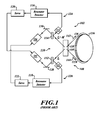
- FIGURE 1 is a block diagram of an exemplary resonator fiber optic gyro 102.
- the operation of an exemplary resonator fiber optic gyro 102 is described hereinbelow, and in greater detail in the commonly assigned U.S. application having serial number 11/298,439, filed on December 9, 2005 , and now published as U.S. 2007/0133003 , which is incorporated by reference herein in its entirety.
- the resonator fiber optic gyro 102 comprises two lasers 104, 106 (e.g., light sources such as tunable lasers, laser diodes, or other suitable light sources) that synthesize light beams, respectively, a resonator 108 circulating light beams in counter-propagating directions and having a recirculator 110 that introduces a portion of the light beams from the lasers 104, 106 into the resonator 108, photodetectors 112, 114 that sample light circulating in the resonator 108, resonance detectors 116, 118 coupled to the photodetectors 114, 112, respectively, that detect the centers of resonance dips for each of the counter-propagating directions of the resonator 108, and servos 120, 122 having an input coupled to the resonance detectors 116, 118, respectively, and an output coupled to the lasers 104, 106, respectively.
- These components of the resonator fiber optic gyro 102 thus form resonance
- the resonator 108 comprises the recirculator 110 and optical fiber coil 136 with a plurality of loops.
- optical fiber coil 136 is a hollow core optical fiber, although any suitable optical fiber may be used.
- Fiber optic coil 136 has a first end 138 and a second end 140. Each end 138, 140 is physically coupled a respective support portion of the recirculator 110.
- the recirculator 110 introduces CW and CCW input light beams into the optical fiber coil 136 and circulates a portion of the modulated light beams through the optical fiber coil 136.
- the recirculator 110 reintroduces light emerging from one end of the optical fiber coil 136 into the other end of the fiber coil 136, thus causing light to propagate through the fiber coil 136 many times.
- the fiber optic gyro 102 senses a rotation rate about an axis of the fiber optic gyro 102. Efficient light recirculation requires precise alignment of the optical fiber coil ends 138, 140.
- a system and method for a fiber optic alignment device on a crystalline substrate support are disclosed.
- An exemplary embodiment of a fiber optic alignment device embodied in a resonator fiber optic gyro is fabricated by a process of forming a crystalline substrate support structure operable to support the first end portion of the optical fiber and the second end portion of the optical fiber; forming a first end V-groove portion and a second end V-groove portion in the support structure; physically coupling the first end portion of the optical fiber to the first end V-groove portion; and physically coupling the second end portion of the optical fiber to the second end V-groove portion.
- an exemplary embodiment is fabricated by a process of forming a crystalline substrate support structure operable to support the first end portion of the optical fiber and the second end portion of the optical fiber; forming a V-groove in the support structure along an axis, the V-groove defined by a central V-groove portion, a first end V-groove portion, and a second end V-groove portion, each of the V-groove portions aligned end-to-end along the axis; physically coupling the first end portion of the optical fiber to the first end V-groove portion so that the first end of the optical fiber is directed towards the central V-groove portion and is aligned along the axis; and physically coupling the second end portion of the optical fiber to the second end V-groove portion so that the second end of the optical fiber is directed towards the central V-groove portion, is aligned along the axis, and is facing the first end of the optical fiber.
- a fiber optic system has an optical fiber defined by a central portion, a first end portion with a first end, and a second end portion with a second end, the first end and the second end operable to transmit and receive light; a first light source operable to generate a first light beam that is receivable by the second end of the optical fiber, the first light beam traveling towards the central portion of the optical fiber; a crystalline substrate support structure with at least one V-groove thereon, the V-groove aligned along an axis, and defined by a central V-groove portion and a first end V-groove portion; a binder operable to physically couple the first end V-groove portion to the first end portion of the optical fiber so that the first end of the optical fiber is directed towards the central V-groove portion and is aligned along the axis; and a light transmissive optical component aligned along the axis and operable to receive the light beam exiting the first end of the optical fiber via
- FIGURE 1 is a block diagram of an exemplary embodiment of a fiber optic gyro
- FIGURE 2 is a view of the orientation of the ends of an optical fiber in accordance with an exemplary embodiment
- FIGURE 3 is a side view of a V-groove fabricated in a silicon crystal based support
- FIGURE 4 is a block diagram of an exemplary embodiment indicating orientation of the ends of the optical fiber with a first arrangement of a plurality of optical elements
- FIGURE 5 is a block diagram of an exemplary embodiment indicating orientation of the ends of the optical fiber with a second arrangement of a plurality of optical elements
- FIGURE 6 is a view of the orientation of the ends of an optical fiber in accordance with an offset V-groove embodiment.
- Embodiments of a V-groove support may be implemented in a variety of fiber optic devices, such as, but not limited to, fiber optic resonator systems that detect absorbed gases, fiber optic systems that detect deformations in an object, and other types of fiber optic systems employing an optical fiber.
- a V-groove is etched into a silicon based optical bench wherein the mask used to etch the V-groove. The mask uses a precise width along the mask pattern of the V-groove. The etching process forms the V-groove such that when the ends of the optical fiber are attached into the V-groove, the optical fiber ends are precisely aligned with each other.
- Embodiments of the V-groove support may be used in various types of fiber optic gyros and other fiber optic devices that require precise alignment of the ends of an optical fiber.
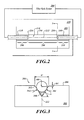
- FIGURE 2 is a view of the orientation of the ends of the fiber optic system 200 in accordance with an exemplary embodiment of a silicon optical bench with a V-groove support.
- the V-groove support resides in the resonator 108.
- the silicon optical bench comprises a support structure 202 with a V-groove 204 disposed thereon.
- the silicon optical bench 202 may be a silicon crystalline substrate structure, such as, but not limited to, a monocrystaline silicon substrate. In other embodiments, a support structure similar to a silicon optical bench may be used with a V-groove 204 thereon.
- the exemplary V-groove 204 includes a central V-groove portion 206 and two end V-groove portions 208, 210.
- the orientation of the V-groove 204 forms an axis 212 that is parallel to the direction of the V-groove 204. Accordingly, each of the V-groove portions 206, 208, 210 are aligned along the axis 212.
- One end portion 138 of the fiber optic system 200 is physically coupled to the end V-groove portion 208.
- the opposing end portion 140 of the fiber optic system 200 is physically coupled to the other end V-groove portion 210.
- Various optic elements may be fabricated on and/or attached to the central V-groove portion 206 of the V-groove 204.
- the end 214 of the fiber optic system 200 is aligned with the axis 212 and is facing the central V-groove portion 206.
- the end 216 of the fiber optic system 200 is aligned with the axis 212 and is facing the central V-groove portion 206. Accordingly, the ends 214 and 216 are facing each other, and are in precise alignment because the ends 214 and 216 reside in the V-groove 204.
- the V-groove portion 206 has an intervening free space 218 between the ends 214 and 216.
- Free space 218 may be filled with a gas or free space 218 may be a vacuum.
- light entering and/or exiting the ends 214 and 216 passes through the intervening free space 218.
- various optical components may also reside in the intervening free space 218 of the centrally located V-groove portion 206.
- FIGURE 3 is a side view along the plane 3-3' ( FIGURE 1 ) of a V-groove 204 fabricated in an exemplary silicon crystal support structure 202.
- the V-groove 204 is formed by anisotropic etching of the silicon crystal support structure 202 along selected planes of the silicon crystal structure, such as crystal planes defined by, but not limited to, the (111) Miller indices.
- the V-groove 204 may be characterized by an angle ⁇ and a width W.
- the angle ⁇ corresponds to the (111) plane.
- the width W is constant along the length of the V-groove 204, and more particularly, along the lengths of the end portions 138, 140. This consistency in the width W is facilitated by a closely controlled mask line and etching process.
- the end portions 138, 140 of the fiber optic system 200 are positioned into the respective end V-groove portions 208, 210, the end portions 138, 140 of the fiber optic system 200 are in contact with side walls 320 of the V-groove 204 at locations 304.
- the locations 304 are a function of the angle ⁇ and the width of the V-groove.
- the end V-groove portions 208, 210 are definable by a length.
- the length may be predefined or variable, and/or the length may be different for the end V-groove portions 208, 210.
- the angle ⁇ of the V-groove 204 is substantially constant along the length of the end V-groove portions 208, 210, thereby improving alignment of the end portions 138, 140 with respect to each other and/or the optics of the fiber optic gyro 102. Since the end portions 138, 140 of the fiber optic system 200 have substantially the same diameter, and since the angle ⁇ and/or the width W are substantially constant for both of the end V-groove portions 208, 210, the distance D1 corresponding to the distance between the surface 306 of the support structure 202 and the center 308 of the end portions 138, 140 of the fiber optic system 200 is substantially the same for both end portions 138, 140.
- the angle ⁇ and the width W of the V-groove 204 is such that the center 308 is below the surface 306.
- the angle ⁇ and/or the width W of the V-groove 204 may be such that the center 308 is level with, or higher than, the surface 306.
- the distance D1 is controllable by defining the width W of the V-groove 204.
- each end portion 138, 140 of the fiber optic system 200 is located at substantially the same position in its respective end V-groove portion 208, 210, the centers 308 of the two end portions 138, 140 are aligned with each other. That is, the end 214 of the end portion 138 is facing, and is in alignment with, the end 216 of the end portion 140.
- the ends 216 and 138 will be exactly in alignment with each other.
- the ends 216 and 138 will be substantially in alignment with each other.
- CW light exits the end 216 and travels in a path that is parallel to the axis 212. Since the center 308 of the end portions 138, 140 of the fiber optic system 200 are aligned with each other, a substantial portion of the exiting CW light is received at the end 214, depending upon the amount of beam spread occurring as the light propagates through free space. The received CW light continues traveling through the fiber optic system 200 in the CW direction.
- CCW light exits the end 214 and travels in a path that is parallel to the axis 212. Since the center 308 of the end portions 138, 140 of the fiber optic system 200 are aligned with each other, a substantial portion of the CCW light is received at the end 216. The received CCW light continues traveling through the fiber optic system 200 in the CCW direction.
- Loss of light due to misalignments between the end portions 138, 140 of the fiber optic system 200 is significantly and unexpectedly reduced since the ends 214, 216 are substantially aligned with each other. That is, a V-groove 204 formed in a precise manner allows precise physical coupling of the end portions 138, 140 of the fiber optic system 200 into the support structure 202 such that the end portions 138, 140 are precisely aligned with each other.
- a binder 310 is used to physically couple the end portions 138, 140 of the fiber optic system 200 into their respective end V-groove portions 208, 210.
- the binder 310 may be a light curable binder, such as, but not limited to an ultra violet (UV) curable binder.
- the binder 310 may alternatively be a heat curable binder.
- Other embodiments may employ any suitable binder 310 to physically couple the end portions 138, 140 to their respective end V-groove portions 208, 210.
- Non-limiting example of such binders 310 include blocks, straps, bars and other types of fasteners.
- FIGURE 4 is a block diagram of an exemplary V-groove embodiment indicating orientation of the ends 214, 216 of the fiber optic system 200 with a first arrangement 400 of a plurality of optical elements.
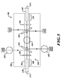
- FIGURE 5 is a block diagram of an exemplary V-groove embodiment indicating orientation of the ends 214, 216 of the fiber optic system 200 with a second arrangement 500 of a plurality of optical elements.
- optical elements include ball lens 402, polarizing filters 404, and transmissive mirrors 406. It is appreciated that any number of selected optical elements 402, 404, 406 may be located in the central V-groove portion 206, and that such selected optical elements 402, 404, 406 may be configured in any desirable manner.
- FIGURE 6 is a view of the orientation of the ends of an optical fiber in accordance with an offset V-groove embodiment 600.
- the offset of the V-grooves 204a, 204b compensates for the offset in light caused by one or more optical elements 602. That is, the offset of the V-groove axis 212a and the V-groove axis 212b corresponds to the amount of light offset from the optical element 602.
- the V-groove 204 may be used to facilitate placement and/or alignment of other optical elements in the fiber optic gyro 102.
- the end portions 138, 140 of the fiber optic system 200 are substantially aligned with each other along the axis 212.
- the path of travel of the light through the the free space of the central V-groove portion 206 is determinable with respect to the location of the V-groove 202, and more particularly, is determinable with respect to the axis 212.
- other optical elements such as the ball lens 402, the polarizing filters 404, the transmissive mirrors 406, or the like may be located in and/or generally aligned with the central V-groove portion 206 in desired positions with respect to the end portions 138, 140. That is, the other optical elements may be positioned with respect to the known location of the V-groove 204, and more particularly, with respect to the axis 212.
- a V-shaped groove 204 is preferred in that a V-shaped groove provides a self-correcting means that orients and positions the end portions 138, 140 with respect to each other.
- a first support structure may have end V-groove portions 208, 210 in a V-shaped configuration at a particular width.
- a second support structure may also have the end V-groove portions 208, 210 in a V-shaped configuration, but having a another width that is different from the V-groove of the first support structure.
- the end portions 138, 140 of their respective fiber optic system 200 will be positioned and oriented such that their respective ends 214, 216 are in alignment with each other.
- the use of a V-groove 204 provides a high degree of tolerance in the design and manufacturing processes.
- Any suitable fabrication means and/or techniques may be used to form a V-groove 204.
- anisotropic etching techniques may be used to form a V-groove.
- two separate V-grooves may be formed.
- the V-grooves are formed using the same mask and are concurrently etched.
- a portion of the first V-groove may be used to position and orient the end portion 138, and a portion of the second V-groove may be used to position and orient the other end portion 140.
- the optical devices can be arranged in any desirable configuration to process the light emitted and/or received by the ends 214, 216 of the fiber optic system 200.
- the transmitted light when light propagates through the silicon partial reflecting mirrors (which are essentially windows with nonzero reflectance), the transmitted light will be transversely displaced relative to the input light. Depending on the index of refraction and the thickness of the window, this displacement is non-negligible.
- the vertical height of the transmitted light is the same as the vertical height of the input light.
- the V-grooves, and any intermediate optics need to be offset to account for this displacement. The displacement is easily calculated and can be accounting for in the fabrication mask. The vertical height is unaffected and is still auto-aligned.
- the end portions 138, 140 of the optical fiber and/or the V-grooves may have a guide means thereon to assist in alignment of the light polarization to a preferred fiber axis.
- the end portions 138, 140 may have one or more flattened portions, notches, stripes and/or other guides thereon.
- Some embodiments of the support structure 202 may have the V-groove 204, or its equivalent, formed internally.
- deep etching processes may be used to form an internal V-groove shaped structure.
- the end portions 138, 140 need to be aligned along a particular light polarization axis.
- the first end portion 138 of the optical fiber is placed into the first end V-groove portion 208, the first end portion is rotated while the beam of light is emitted from the first end 214.
- the first end portion 138 is secured in the V-groove portion 208.
- the second end portion 140 of the optical fiber is placed into the first end V-groove portion 210, the second end portion 140 is rotated while the CW beam of light is emitted from the first end 216.
- the second end portion 140 is secured in the V-groove portion 210
Landscapes
- Physics & Mathematics (AREA)
- Optics & Photonics (AREA)
- General Physics & Mathematics (AREA)
- Engineering & Computer Science (AREA)
- Electromagnetism (AREA)
- Power Engineering (AREA)
- Radar, Positioning & Navigation (AREA)
- Remote Sensing (AREA)
- Optical Couplings Of Light Guides (AREA)
- Mechanical Coupling Of Light Guides (AREA)
- Gyroscopes (AREA)
Abstract
Description
- Gyros measure rotation rates or changes in angular velocity about an axis. A basic conventional fiber optic gyro (FOG) includes a light source, a beam generating device, and a coil of optical fiber coupled to the beam generating device that encircles an area. The beam generating device transmits light beams into the coil that propagate in a clockwise (CW) direction and a counter-clockwise (CCW) direction along the core of the optical fiber. The two counter-propagating (CW and CCW) beams experience different path lengths while propagating around a rotating path, and the difference in the two path lengths is proportional to the rotational rate. FOGs have accuracies that generally increase with the area encircled by the optical path of the light beams. Thus, the larger the area enclosed by the optical path, the greater the signal-to-noise ratio of the FOG. Also, to improve the signal-to-noise ratio of the FOG, the optical path may be increased by increasing the number of turns of the coil.
- In a resonator fiber optic gyro (RFOG), the counter-propagating light beams are monochromatic and recirculate through multiple turns of the coil and for multiple passes through the coil using a recirculator such as a fiber coupler or other reflective device. The beam generating device typically modulates and/or shifts the frequencies of each of the counter-propagating light beams so that the resonance frequencies of the resonant coil may be observed. The resonance frequencies for each of the CW and CCW paths through the coil are based on a constructive interference of successively recirculated beams in each optical path. A rotation of the coil produces a shift in the respective resonance frequencies of the resonant coil and the frequency difference associated with tuning the CW beam and CCW beam frequencies to match the coil's resonance frequency shift due to rotation indicates the rotation rate. A reflective mirror may be used to recirculate the counter-propagating light beams in the coil but this typically reduces the signal-to-noise ratio from losses generated at the transition from the mirror to the coil.
- Accordingly, it is desirable to provide a fiber optic gyro capable of measuring rotational rates with an accuracy sufficient for navigation systems. In addition, it is desirable to provide a high accuracy fiber optic gyro for integration with relatively small platforms and made relatively inexpensively. Good performance of the RFOG is is premised on having a low fiber-to-fiber coupling loss so that the light makes many trips through the fiber coil. The prior art in this field uses a highly reflective mirror (e.g.: 98% reflectivity) to do the fiber-to-fiber coupling. While this architecture uses the advantage that reflective mirror coatings can be made very precisely with multiple dielectric coatings, it suffers a serious disadvantage, namely that it is difficult to insure the two fiber ends are aligned to each other. An implementation of this design would require time consuming and expensive active and by-hand alignments.
-
FIGURE 1 is a block diagram of an exemplary resonator fiberoptic gyro 102. The operation of an exemplary resonator fiberoptic gyro 102 is described hereinbelow, and in greater detail in the commonly assignedU.S. application having serial number 11/298,439, filed on December 9, 2005 U.S. 2007/0133003 , which is incorporated by reference herein in its entirety. The resonator fiberoptic gyro 102 comprises twolasers 104, 106 (e.g., light sources such as tunable lasers, laser diodes, or other suitable light sources) that synthesize light beams, respectively, aresonator 108 circulating light beams in counter-propagating directions and having arecirculator 110 that introduces a portion of the light beams from thelasers resonator 108,photodetectors resonator 108,resonance detectors photodetectors resonator 108, andservos resonance detectors lasers optic gyro 102 thus formresonance tracking loops - The
resonator 108 comprises therecirculator 110 andoptical fiber coil 136 with a plurality of loops. In an exemplary embodiment,optical fiber coil 136 is a hollow core optical fiber, although any suitable optical fiber may be used. Fiberoptic coil 136 has afirst end 138 and asecond end 140. Eachend recirculator 110. Therecirculator 110 introduces CW and CCW input light beams into theoptical fiber coil 136 and circulates a portion of the modulated light beams through theoptical fiber coil 136. Therecirculator 110 reintroduces light emerging from one end of theoptical fiber coil 136 into the other end of thefiber coil 136, thus causing light to propagate through thefiber coil 136 many times. By application of the Sagnac Effect, the fiberoptic gyro 102 senses a rotation rate about an axis of the fiberoptic gyro 102. Efficient light recirculation requires precise alignment of the opticalfiber coil ends - A system and method for a fiber optic alignment device on a crystalline substrate support are disclosed. An exemplary embodiment of a fiber optic alignment device embodied in a resonator fiber optic gyro is fabricated by a process of forming a crystalline substrate support structure operable to support the first end portion of the optical fiber and the second end portion of the optical fiber; forming a first end V-groove portion and a second end V-groove portion in the support structure; physically coupling the first end portion of the optical fiber to the first end V-groove portion; and physically coupling the second end portion of the optical fiber to the second end V-groove portion.
- In accordance with further aspects, an exemplary embodiment is fabricated by a process of forming a crystalline substrate support structure operable to support the first end portion of the optical fiber and the second end portion of the optical fiber; forming a V-groove in the support structure along an axis, the V-groove defined by a central V-groove portion, a first end V-groove portion, and a second end V-groove portion, each of the V-groove portions aligned end-to-end along the axis; physically coupling the first end portion of the optical fiber to the first end V-groove portion so that the first end of the optical fiber is directed towards the central V-groove portion and is aligned along the axis; and physically coupling the second end portion of the optical fiber to the second end V-groove portion so that the second end of the optical fiber is directed towards the central V-groove portion, is aligned along the axis, and is facing the first end of the optical fiber.
- In accordance with other aspects, a fiber optic system has an optical fiber defined by a central portion, a first end portion with a first end, and a second end portion with a second end, the first end and the second end operable to transmit and receive light; a first light source operable to generate a first light beam that is receivable by the second end of the optical fiber, the first light beam traveling towards the central portion of the optical fiber; a crystalline substrate support structure with at least one V-groove thereon, the V-groove aligned along an axis, and defined by a central V-groove portion and a first end V-groove portion; a binder operable to physically couple the first end V-groove portion to the first end portion of the optical fiber so that the first end of the optical fiber is directed towards the central V-groove portion and is aligned along the axis; and a light transmissive optical component aligned along the axis and operable to receive the light beam exiting the first end of the optical fiber via an intervening free space.
- Preferred and alternative embodiments are described in detail below with reference to the following drawings:
-
FIGURE 1 is a block diagram of an exemplary embodiment of a fiber optic gyro; -
FIGURE 2 is a view of the orientation of the ends of an optical fiber in accordance with an exemplary embodiment; -
FIGURE 3 is a side view of a V-groove fabricated in a silicon crystal based support; -
FIGURE 4 is a block diagram of an exemplary embodiment indicating orientation of the ends of the optical fiber with a first arrangement of a plurality of optical elements; -
FIGURE 5 is a block diagram of an exemplary embodiment indicating orientation of the ends of the optical fiber with a second arrangement of a plurality of optical elements; and -
FIGURE 6 is a view of the orientation of the ends of an optical fiber in accordance with an offset V-groove embodiment. - Embodiments of a V-groove support may be implemented in a variety of fiber optic devices, such as, but not limited to, fiber optic resonator systems that detect absorbed gases, fiber optic systems that detect deformations in an object, and other types of fiber optic systems employing an optical fiber. In an exemplary embodiment, a V-groove is etched into a silicon based optical bench wherein the mask used to etch the V-groove. The mask uses a precise width along the mask pattern of the V-groove. The etching process forms the V-groove such that when the ends of the optical fiber are attached into the V-groove, the optical fiber ends are precisely aligned with each other. Accordingly, light may be recirculated between the precisely aligned ends of the optical fiber. Embodiments of the V-groove support may be used in various types of fiber optic gyros and other fiber optic devices that require precise alignment of the ends of an optical fiber.
-
FIGURE 2 is a view of the orientation of the ends of the fiberoptic system 200 in accordance with an exemplary embodiment of a silicon optical bench with a V-groove support. The V-groove support resides in theresonator 108. The silicon optical bench comprises asupport structure 202 with a V-groove 204 disposed thereon. The siliconoptical bench 202 may be a silicon crystalline substrate structure, such as, but not limited to, a monocrystaline silicon substrate. In other embodiments, a support structure similar to a silicon optical bench may be used with a V-groove 204 thereon. - The exemplary V-
groove 204 includes a central V-groove portion 206 and two end V-groove portions groove 204 forms anaxis 212 that is parallel to the direction of the V-groove 204. Accordingly, each of the V-groove portions axis 212. - One
end portion 138 of the fiberoptic system 200 is physically coupled to the end V-groove portion 208. Theopposing end portion 140 of the fiberoptic system 200 is physically coupled to the other end V-groove portion 210. Various optic elements may be fabricated on and/or attached to the central V-groove portion 206 of the V-groove 204. - When the optical
fiber end portion 138 is physically coupled (i.e. glued, epoxied, or soldered) to the V-groove end portion 208, theend 214 of the fiberoptic system 200 is aligned with theaxis 212 and is facing the central V-groove portion 206. When the opticalfiber end portion 140 is physically coupled to the V-groove end portion 210, theend 216 of the fiberoptic system 200 is aligned with theaxis 212 and is facing the central V-groove portion 206. Accordingly, theends ends groove 204. - The V-
groove portion 206 has an interveningfree space 218 between theends Free space 218 may be filled with a gas orfree space 218 may be a vacuum. Thus, light entering and/or exiting theends free space 218. As noted above, various optical components may also reside in the interveningfree space 218 of the centrally located V-groove portion 206. -
FIGURE 3 is a side view along the plane 3-3' (FIGURE 1 ) of a V-groove 204 fabricated in an exemplary siliconcrystal support structure 202. The V-groove 204 is formed by anisotropic etching of the siliconcrystal support structure 202 along selected planes of the silicon crystal structure, such as crystal planes defined by, but not limited to, the (111) Miller indices. The V-groove 204 may be characterized by an angle α and a width W. When the V-groove 204 is etched into a silicon bench, the angle α corresponds to the (111) plane. Preferably, the width W is constant along the length of the V-groove 204, and more particularly, along the lengths of theend portions - When the
end portions fiber optic system 200 are positioned into the respective end V-groove portions end portions fiber optic system 200 are in contact with side walls 320 of the V-groove 204 atlocations 304. As noted above, thelocations 304 are a function of the angle α and the width of the V-groove. - The end V-
groove portions groove portions - Further, the angle α of the V-
groove 204 is substantially constant along the length of the end V-groove portions end portions fiber optic gyro 102. Since theend portions fiber optic system 200 have substantially the same diameter, and since the angle α and/or the width W are substantially constant for both of the end V-groove portions surface 306 of thesupport structure 202 and thecenter 308 of theend portions fiber optic system 200 is substantially the same for bothend portions groove 204 is such that thecenter 308 is below thesurface 306. However, the angle α and/or the width W of the V-groove 204 may be such that thecenter 308 is level with, or higher than, thesurface 306. The distance D1 is controllable by defining the width W of the V-groove 204. - Since each
end portion fiber optic system 200 is located at substantially the same position in its respective end V-groove portion centers 308 of the twoend portions end 214 of theend portion 138 is facing, and is in alignment with, theend 216 of theend portion 140. Ideally, with identical dimensions of theend portion groove portions ends end portion groove portions ends - With a V-groove embodiment implemented in a resonator fiber optic gyro, CW light exits the
end 216 and travels in a path that is parallel to theaxis 212. Since thecenter 308 of theend portions fiber optic system 200 are aligned with each other, a substantial portion of the exiting CW light is received at theend 214, depending upon the amount of beam spread occurring as the light propagates through free space. The received CW light continues traveling through thefiber optic system 200 in the CW direction. - CCW light exits the
end 214 and travels in a path that is parallel to theaxis 212. Since thecenter 308 of theend portions fiber optic system 200 are aligned with each other, a substantial portion of the CCW light is received at theend 216. The received CCW light continues traveling through thefiber optic system 200 in the CCW direction. - Loss of light due to misalignments between the
end portions fiber optic system 200 is significantly and unexpectedly reduced since theends groove 204 formed in a precise manner allows precise physical coupling of theend portions fiber optic system 200 into thesupport structure 202 such that theend portions - A binder 310 is used to physically couple the
end portions fiber optic system 200 into their respective end V-groove portions end portions groove portions -
FIGURE 4 is a block diagram of an exemplary V-groove embodiment indicating orientation of theends fiber optic system 200 with afirst arrangement 400 of a plurality of optical elements.FIGURE 5 is a block diagram of an exemplary V-groove embodiment indicating orientation of theends fiber optic system 200 with asecond arrangement 500 of a plurality of optical elements. Non-limiting examples of optical elements includeball lens 402,polarizing filters 404, and transmissive mirrors 406. It is appreciated that any number of selectedoptical elements groove portion 206, and that such selectedoptical elements -
FIGURE 6 is a view of the orientation of the ends of an optical fiber in accordance with an offset V-groove embodiment 600. The offset of the V-grooves optical elements 602. That is, the offset of the V-groove axis 212a and the V-groove axis 212b corresponds to the amount of light offset from theoptical element 602. - The V-
groove 204 may be used to facilitate placement and/or alignment of other optical elements in thefiber optic gyro 102. As noted above, theend portions fiber optic system 200 are substantially aligned with each other along theaxis 212. Thus, the path of travel of the light through the the free space of the central V-groove portion 206 is determinable with respect to the location of the V-groove 202, and more particularly, is determinable with respect to theaxis 212. Accordingly, other optical elements, such as theball lens 402, thepolarizing filters 404, the transmissive mirrors 406, or the like may be located in and/or generally aligned with the central V-groove portion 206 in desired positions with respect to theend portions groove 204, and more particularly, with respect to theaxis 212. - In the various embodiments, a V-shaped
groove 204 is preferred in that a V-shaped groove provides a self-correcting means that orients and positions theend portions groove portions groove portions end portions fiber optic system 200 will be positioned and oriented such that theirrespective ends groove 204 provides a high degree of tolerance in the design and manufacturing processes. - Any suitable fabrication means and/or techniques may be used to form a V-
groove 204. For example, anisotropic etching techniques may be used to form a V-groove. - In some embodiments, two separate V-grooves may be formed. Preferably, the V-grooves are formed using the same mask and are concurrently etched. A portion of the first V-groove may be used to position and orient the
end portion 138, and a portion of the second V-groove may be used to position and orient theother end portion 140. Because the V-grooves 204 position and orient their respective theend portions fiber optic system 200 in a known manner, the optical devices can be arranged in any desirable configuration to process the light emitted and/or received by theends fiber optic system 200. - For example, and in reality, when light propagates through the silicon partial reflecting mirrors (which are essentially windows with nonzero reflectance), the transmitted light will be transversely displaced relative to the input light. Depending on the index of refraction and the thickness of the window, this displacement is non-negligible. The vertical height of the transmitted light is the same as the vertical height of the input light. In order to maximally couple light from fiber-to-fiber, the V-grooves, and any intermediate optics, need to be offset to account for this displacement. The displacement is easily calculated and can be accounting for in the fabrication mask. The vertical height is unaffected and is still auto-aligned.
- In some embodiments, the
end portions end portions - Some embodiments of the
support structure 202 may have the V-groove 204, or its equivalent, formed internally. For example, in embodiments that have a silicontype support structure 202, deep etching processes may be used to form an internal V-groove shaped structure. - In some embodiments, the
end portions first end portion 138 of the optical fiber is placed into the first end V-groove portion 208, the first end portion is rotated while the beam of light is emitted from thefirst end 214. When a maximum light transmission of the beam of light emitted from thefirst end 214 is detected, thefirst end portion 138 is secured in the V-groove portion 208. When thesecond end portion 140 of the optical fiber is placed into the first end V-groove portion 210, thesecond end portion 140 is rotated while the CW beam of light is emitted from thefirst end 216. When a maximum light transmission of the beam of light emitted from thesecond end 216 is detected, thesecond end portion 140 is secured in the V-groove portion 210 - While the preferred embodiment of the invention has been illustrated and described, as noted above, many changes can be made without departing from the spirit and scope of the invention. Accordingly, the scope of the invention is not limited by the disclosure of the preferred embodiment. Instead, the invention should be determined entirely by reference to the claims that follow.
- The embodiments of the invention in which an exclusive property or privilege is claimed are defined as follows:
Claims (9)
- A method for constructing a fiber optic system (200) having an optical fiber (136) defined by a central portion, a first end portion (138) with a first end (214), and a second end portion (140) with a second end (216), the method comprising:forming a crystalline substrate support structure (202) operable to support the first end portion (138) of the optical fiber and the second end portion (140) of the optical fiber;forming a V-groove (204) in the support structure (140) along an axis, the V-groove (204) defined by a central V-groove portion (206), a first end V-groove portion (208), and a second end V-groove portion (210), each of the V-groove portions aligned end-to-end along the axis (212);physically coupling the first end portion (138) of the optical fiber (136) to the first end V-groove portion (208) so that the first end (214) of the optical fiber (136) is directed towards the central V-groove portion (206) and is aligned along the axis (214); andphysically coupling the second end portion (140) of the optical fiber (136) to the second end V-groove portion (210) so that the second end (216) of the optical fiber (136) is directed towards the central V-groove portion (206), is aligned along the axis (212), and is facing the first end (214) of the optical fiber (136).
- The method of Claim 1, wherein forming the V-groove comprises:anisotropically etching the crystalline substrate support structure along a (111) plane to form the V-groove (204).
- The method of Claim 1, further comprising:placing an optical element to the central V-groove portion (206) in alignment with the axis (212).
- The method of Claim 1, wherein forming the V-groove (204) comprises:anisotropically etching the crystalline substrate support structure using a first mask having a width corresponding to a width of the first end V-groove portion (208); andanisotropically etching the crystalline substrate support structure (202) using a second mask having the width corresponding to a width of the second end V-groove portion (210).
- The method of Claim 1, wherein physically coupling the first end portion (138) of the optical fiber (216) to the first end V-groove portion (208) further comprises:placing the first end portion (138) of the optical fiber (136) into the first end V-groove portion (208);rotating the first end portion (138) of the optical fiber (136);monitoring the beam of light emitted from the second end (216) of the optical fiber (136) for a maximum light transmission of the beam of light; andin response to detecting the maximum light transmission, physically coupling the first end portion (138) of the optical fiber to the first end V-groove portion (208).
- The method of Claim 7, wherein the central V-groove portion (206) defines a first intervening free space and a second intervening free space, and further comprising:physically coupling a first ball lens (402) in a portion of the first intervening free space, wherein the first ball lens (402) is in alignment with the axis (212); andphysically coupling a second ball lens (402) in a portion of the second intervening free space, wherein the second ball lens (402) is in alignment with the axis (212),wherein the first ball lens (402) is operable to receive the first light beam from the first end (214) of the optical fiber (136), is operable to communicate the first light beam to the second ball lens (402), is operable to receive the second light beam from the second ball lens (402), and is operable to communicate the second light beam to the first end (214) of the optical fiber, and
wherein the second ball lens (402) is operable to receive the second light beam from the second end (216) of the optical fiber (136), is operable to communicate the second light beam to the first ball lens (402), is operable to receive the first light beam from the first ball lens (402), and is operable to communicate the first light beam to the second end (216) of the optical fiber - A fiber optic system, comprising:a crystalline substrate support structure (202); anda V-groove (204) residing on the crystalline substrate (202), the V-groove (204) aligned along an axis (212), and defined by a central portion (206) and a first end portion (208), wherein a first end (138) of an optical fiber (136) is securable in the first end portion (208) of the V-groove (204) such that an optical component aligned along the axis (212) is operable to receive a light beam exiting the end (214) of the optical fiber (136), and wherein the V-groove (204) is further defined by a second end portion (210) such that a second end (216) of the optical fiber (136) secured to the second end portion (210) of the V-groove (204) and is aligned along the axis (212).
- The fiber optic system of Claim 7, wherein the crystalline substrate (202) is a silicon optical bench, and the V-groove (204) is anisotropically etched into the silicon optical bench along a (111) plane.
- The fiber optic system of Claim 7, further comprising:a first ball lens (402) in a portion of a first intervening free space in the central portion (206) of the V-groove (204), wherein the first ball lens (402) is in alignment with the axis (212); anda second ball lens (402) in a portion of a second intervening free space in the central portion (206) of the V-groove (204), wherein the second ball lens (402) is in alignment with the axis (212),wherein the first ball lens (402) is operable to receive the first light beam from the first end of the optical fiber (136), is operable to communicate the first light beam to the second ball lens (402), is operable to receive the second light beam from the second ball lens (402), and is operable to communicate the second light beam to the first end (214) of the optical fiber (136), and
wherein the second ball lens (402) is operable to receive the second light beam from the second end (216) of the optical fiber (136), is operable to communicate the second light beam to the first ball lens (402), is operable to receive the first light beam from the first ball lens (402), and is operable to communicate the first light beam to the second end (216) of the optical fiber (136).
Applications Claiming Priority (1)
| Application Number | Priority Date | Filing Date | Title |
|---|---|---|---|
| US11/969,822 US7802928B2 (en) | 2008-01-04 | 2008-01-04 | System and method for fiber based resonator coupling |
Publications (3)
| Publication Number | Publication Date |
|---|---|
| EP2078970A2 true EP2078970A2 (en) | 2009-07-15 |
| EP2078970A3 EP2078970A3 (en) | 2010-11-03 |
| EP2078970B1 EP2078970B1 (en) | 2016-03-09 |
Family
ID=40674035
Family Applications (1)
| Application Number | Title | Priority Date | Filing Date |
|---|---|---|---|
| EP08172650.7A Active EP2078970B1 (en) | 2008-01-04 | 2008-12-22 | System and method for optical fiber based resonator coupling |
Country Status (3)
| Country | Link |
|---|---|
| US (1) | US7802928B2 (en) |
| EP (1) | EP2078970B1 (en) |
| JP (1) | JP5590794B2 (en) |
Cited By (3)
| Publication number | Priority date | Publication date | Assignee | Title |
|---|---|---|---|---|
| EP2530431A1 (en) * | 2011-06-01 | 2012-12-05 | Honeywell International Inc. | Improved optical filtering for resonator-fiber-optic gyroscopes |
| EP2128566A3 (en) * | 2008-05-30 | 2015-09-23 | Honeywell International Inc. | Reliable low loss hollow core fiber resonator |
| CN111490440A (en) * | 2020-04-30 | 2020-08-04 | 南京理工大学 | Optical gate for energy-division high-power optical fiber laser |
Families Citing this family (6)
| Publication number | Priority date | Publication date | Assignee | Title |
|---|---|---|---|---|
| US8121487B2 (en) * | 2008-02-05 | 2012-02-21 | Honeywell International Inc. | System and method for free space micro machined optical bench |
| US8223341B2 (en) * | 2010-05-28 | 2012-07-17 | Honeywell International Inc. | System and method for enhancing signal-to-noise ratio of a resonator fiber optic gyroscope |
| US8213019B2 (en) | 2010-09-07 | 2012-07-03 | Honeywell International Inc. | RFOG with optical heterodyning for optical signal discrimination |
| US8947671B2 (en) | 2013-02-22 | 2015-02-03 | Honeywell International Inc. | Method and system for detecting optical ring resonator resonance frequencies and free spectral range to reduce the number of lasers in a resonator fiber optic gyroscope |
| US9001336B1 (en) | 2013-10-07 | 2015-04-07 | Honeywell International Inc. | Methods and apparatus of tracking/locking resonator free spectral range and its application in resonator fiber optic gyroscope |
| KR20170071923A (en) * | 2015-12-16 | 2017-06-26 | 삼성전자주식회사 | An Optical Gas Sensor |
Citations (1)
| Publication number | Priority date | Publication date | Assignee | Title |
|---|---|---|---|---|
| US20070133003A1 (en) | 2005-12-09 | 2007-06-14 | Honeywell International, Inc. | System and method for stabilizing light sources in resonator gyro |
Family Cites Families (37)
| Publication number | Priority date | Publication date | Assignee | Title |
|---|---|---|---|---|
| US4135822A (en) * | 1976-01-19 | 1979-01-23 | Massachusetts Institute Of Technology | Laser gyroscope |
| CA1230663A (en) * | 1982-04-28 | 1987-12-22 | Kenichi Yoshida | Optical fiber gyro |
| JPS5960212A (en) * | 1982-09-30 | 1984-04-06 | Fujitsu Ltd | Optical fiber gyro system |
| BR8208104A (en) * | 1982-11-12 | 1984-10-02 | Univ Leland Stanford Junior | FIBER OPTIC SWITCH AND DISCREETLY VARIABLE RETARDING LINE |
| US4549782A (en) * | 1983-06-06 | 1985-10-29 | At&T Bell Laboratories | Active optical fiber tap |
| CA1255382A (en) * | 1984-08-10 | 1989-06-06 | Masao Kawachi | Hybrid optical integrated circuit with alignment guides |
| FR2582800B1 (en) * | 1985-05-30 | 1987-07-17 | Thomson Csf | SINGLE-MODE OPTICAL FIBER RING INTERFEROMETRIC DEVICE |
| JPS61286713A (en) * | 1985-06-13 | 1986-12-17 | Mitsubishi Precision Co Ltd | Optical fiber gyroscope |
| KR910009667B1 (en) * | 1987-10-29 | 1991-11-25 | 미츠비시 덴키 가부시키가이샤 | Optical communication device |
| US4810557A (en) * | 1988-03-03 | 1989-03-07 | American Telephone And Telegraph Company, At&T Bell Laboratories | Method of making an article comprising a tandem groove, and article produced by the method |
| GB8827242D0 (en) * | 1988-11-22 | 1988-12-29 | Plessey Co Plc | Optical coupling of optical fibres & optical devices |
| US5393371A (en) * | 1989-12-18 | 1995-02-28 | Litton Systems, Inc. | Integrated optics chips and laser ablation methods for attachment of optical fibers thereto for LiNbO3 substrates |
| US5243671A (en) * | 1990-07-19 | 1993-09-07 | Gte Laboratories Incorporated | Laser-to-fiber coupling apparatus |
| US5119448A (en) * | 1990-09-21 | 1992-06-02 | Tacan Corporation | Modular micro-optical systems and method of making such systems |
| JPH0774343A (en) * | 1993-08-31 | 1995-03-17 | Fujitsu Ltd | Integrated optical device and manufacturing method thereof |
| US5537671A (en) * | 1995-02-10 | 1996-07-16 | The Board Of Trustees Of The Leland Stanford Junior University | Technique of reducing the Kerr effect and extending the dynamic range in a brillouin fiber optic gyroscope |
| US5872877A (en) * | 1997-02-04 | 1999-02-16 | Intellisense Corporation | Passive resonant optical microfabricated inertial sensor and method using same |
| US5857049A (en) * | 1997-05-05 | 1999-01-05 | Lucent Technologies, Inc., | Precision alignment of optoelectronic devices |
| US6393183B1 (en) * | 1998-08-13 | 2002-05-21 | Eugene Robert Worley | Opto-coupler device for packaging optically coupled integrated circuits |
| FR2793037B1 (en) * | 1999-04-28 | 2001-08-10 | France Telecom | ASSEMBLY OF AN OPTICAL INTEGRATED CIRCUIT CHIP ON A FIBER OPTIC CONNECTION PLATFORM TO FORM A MINIATURE OPTICAL COMPONENT |
| US6496623B2 (en) * | 2000-03-22 | 2002-12-17 | Matsushita Electric Industrial Co., Ltd. | Optical device, optical communication component and optical transmission apparatus |
| US6748132B1 (en) * | 2001-02-26 | 2004-06-08 | K2 Optronics, Inc. | Wavelength add drop element for configurable add drop multiplexing |
| US6580858B2 (en) * | 2001-04-30 | 2003-06-17 | Xerox Corporation | Micro-opto-electro-mechanical system (MOEMS) |
| JP2003098359A (en) * | 2001-09-25 | 2003-04-03 | Matsushita Electric Ind Co Ltd | Semiconductor light emitting device |
| US6751395B1 (en) * | 2001-11-09 | 2004-06-15 | Active Optical Networks, Inc. | Micro-electro-mechanical variable optical attenuator |
| JP2003215514A (en) * | 2002-01-23 | 2003-07-30 | Kyocera Corp | Variable optical attenuator, method of manufacturing the same, and optical module |
| US6864509B2 (en) * | 2002-02-06 | 2005-03-08 | Eugene Robert Worley | Packaging optically coupled integrated circuits using flip-chip methods |
| US20040047536A1 (en) * | 2002-09-05 | 2004-03-11 | Pickrell Gary R. | Creep and viscous flow resistant fiber optic sensor |
| JP3914124B2 (en) * | 2002-09-18 | 2007-05-16 | 沖電気工業株式会社 | Optical module |
| AU2003278747A1 (en) * | 2002-09-25 | 2004-04-19 | Xponent Photonics Inc | Optical assemblies for free-space optical propagation between waveguide(s) and/or fiber(s) |
| US6874950B2 (en) * | 2002-12-17 | 2005-04-05 | International Business Machines Corporation | Devices and methods for side-coupling optical fibers to optoelectronic components |
| US6985646B2 (en) * | 2003-01-24 | 2006-01-10 | Xponent Photonics Inc | Etched-facet semiconductor optical component with integrated end-coupled waveguide and methods of fabrication and use thereof |
| CN100365775C (en) * | 2003-05-23 | 2008-01-30 | 罗姆和哈斯电子材料有限责任公司 | Etching method for micromachining crystalline materials and devices produced by the method |
| US6985645B2 (en) * | 2003-09-24 | 2006-01-10 | International Business Machines Corporation | Apparatus and methods for integrally packaging optoelectronic devices, IC chips and optical transmission lines |
| US7106448B1 (en) * | 2004-02-17 | 2006-09-12 | Sandia Corporation | Integrated resonant micro-optical gyroscope and method of fabrication |
| JP2007033609A (en) * | 2005-07-25 | 2007-02-08 | Oki Electric Ind Co Ltd | Method of manufacturing optical module |
| JP2007294523A (en) * | 2006-04-21 | 2007-11-08 | Oki Electric Ind Co Ltd | Surface packaging type optical coupler, packaging method therefor and manufacturing method therefor |
-
2008
- 2008-01-04 US US11/969,822 patent/US7802928B2/en active Active
- 2008-12-22 EP EP08172650.7A patent/EP2078970B1/en active Active
- 2008-12-26 JP JP2008332382A patent/JP5590794B2/en not_active Expired - Fee Related
Patent Citations (1)
| Publication number | Priority date | Publication date | Assignee | Title |
|---|---|---|---|---|
| US20070133003A1 (en) | 2005-12-09 | 2007-06-14 | Honeywell International, Inc. | System and method for stabilizing light sources in resonator gyro |
Cited By (5)
| Publication number | Priority date | Publication date | Assignee | Title |
|---|---|---|---|---|
| EP2128566A3 (en) * | 2008-05-30 | 2015-09-23 | Honeywell International Inc. | Reliable low loss hollow core fiber resonator |
| EP2530431A1 (en) * | 2011-06-01 | 2012-12-05 | Honeywell International Inc. | Improved optical filtering for resonator-fiber-optic gyroscopes |
| US8446590B2 (en) | 2011-06-01 | 2013-05-21 | Honeywell International Inc. | Optical filtering for resonator-fiber-optic gyroscopes |
| CN111490440A (en) * | 2020-04-30 | 2020-08-04 | 南京理工大学 | Optical gate for energy-division high-power optical fiber laser |
| CN111490440B (en) * | 2020-04-30 | 2021-10-19 | 南京理工大学 | Optical gate for energy-division high-power optical fiber laser |
Also Published As
| Publication number | Publication date |
|---|---|
| JP5590794B2 (en) | 2014-09-17 |
| US7802928B2 (en) | 2010-09-28 |
| US20090175578A1 (en) | 2009-07-09 |
| EP2078970A3 (en) | 2010-11-03 |
| JP2009199065A (en) | 2009-09-03 |
| EP2078970B1 (en) | 2016-03-09 |
Similar Documents
| Publication | Publication Date | Title |
|---|---|---|
| EP2078970B1 (en) | System and method for optical fiber based resonator coupling | |
| JP5096858B2 (en) | Optical resonator gyroscope and method for reducing resonance asymmetry error | |
| US11415419B2 (en) | Polarizer implemented in a photonic integrated circuit for use in a fiber optic gyroscope | |
| JP5474282B2 (en) | Integrated optical rotation sensor and method for detecting rotation rate | |
| JP4818979B2 (en) | Optical resonator gyro with external resonator beam generator | |
| JP5784653B2 (en) | Transmission mode RFOG and method for detecting rotation in RFOG | |
| EP0616195B1 (en) | Fiber optic gyroscope | |
| EP2957863B1 (en) | Small low cost resonator fiber optic gyroscope with reduced optical errors | |
| US8103140B2 (en) | Interferometric fiber optic gyroscope with silicon optical bench front-end | |
| EP3447446B1 (en) | Systems and methods for reducing polarization-related bias errors in rfogs | |
| EP3421934B1 (en) | Resonant fiber optic gyroscope with hollow core fiber | |
| Guo et al. | Three-axis interferometric fiber optic gyroscope with silica integrated coupler chip | |
| JP2007139780A (en) | Optical gyro with free space resonator and method of sensing inertial rotational speed | |
| EP2000795A2 (en) | Improved fiber optic chemical sensor | |
| CN110554464B (en) | A miniaturized single-polarization fiber resonator | |
| EP0373200B1 (en) | Sagnac Ring Rotation Sensor and Method of Use thereof | |
| EP2149782A2 (en) | Fiber optic gyroscope | |
| JP2009036767A (en) | Apparatus and method for detecting harmful substances | |
| KR100210968B1 (en) | Fiber optic gyroscope with low birefringence | |
| US7554738B2 (en) | Optical system with beam propagation extension |
Legal Events
| Date | Code | Title | Description |
|---|---|---|---|
| PUAI | Public reference made under article 153(3) epc to a published international application that has entered the european phase |
Free format text: ORIGINAL CODE: 0009012 |
|
| 17P | Request for examination filed |
Effective date: 20081222 |
|
| AK | Designated contracting states |
Kind code of ref document: A2 Designated state(s): AT BE BG CH CY CZ DE DK EE ES FI FR GB GR HR HU IE IS IT LI LT LU LV MC MT NL NO PL PT RO SE SI SK TR |
|
| AX | Request for extension of the european patent |
Extension state: AL BA MK RS |
|
| PUAL | Search report despatched |
Free format text: ORIGINAL CODE: 0009013 |
|
| AK | Designated contracting states |
Kind code of ref document: A3 Designated state(s): AT BE BG CH CY CZ DE DK EE ES FI FR GB GR HR HU IE IS IT LI LT LU LV MC MT NL NO PL PT RO SE SI SK TR |
|
| AX | Request for extension of the european patent |
Extension state: AL BA MK RS |
|
| AKX | Designation fees paid |
Designated state(s): DE FR |
|
| RIC1 | Information provided on ipc code assigned before grant |
Ipc: G02B 6/26 20060101ALN20150806BHEP Ipc: G01C 19/72 20060101ALN20150806BHEP Ipc: G02B 6/42 20060101ALN20150806BHEP Ipc: G02B 6/36 20060101AFI20150806BHEP |
|
| GRAP | Despatch of communication of intention to grant a patent |
Free format text: ORIGINAL CODE: EPIDOSNIGR1 |
|
| INTG | Intention to grant announced |
Effective date: 20150924 |
|
| GRAS | Grant fee paid |
Free format text: ORIGINAL CODE: EPIDOSNIGR3 |
|
| RAP1 | Party data changed (applicant data changed or rights of an application transferred) |
Owner name: HONEYWELL INTERNATIONAL INC. |
|
| RIC1 | Information provided on ipc code assigned before grant |
Ipc: G01C 19/72 20060101ALN20151204BHEP Ipc: G02B 6/42 20060101ALN20151204BHEP Ipc: G02B 6/36 20060101AFI20151204BHEP Ipc: G02B 6/26 20060101ALN20151204BHEP |
|
| INTG | Intention to grant announced |
Effective date: 20151223 |
|
| GRAA | (expected) grant |
Free format text: ORIGINAL CODE: 0009210 |
|
| AK | Designated contracting states |
Kind code of ref document: B1 Designated state(s): DE FR |
|
| REG | Reference to a national code |
Ref country code: DE Ref legal event code: R096 Ref document number: 602008042665 Country of ref document: DE |
|
| REG | Reference to a national code |
Ref country code: FR Ref legal event code: PLFP Year of fee payment: 9 |
|
| REG | Reference to a national code |
Ref country code: DE Ref legal event code: R097 Ref document number: 602008042665 Country of ref document: DE |
|
| PLBE | No opposition filed within time limit |
Free format text: ORIGINAL CODE: 0009261 |
|
| STAA | Information on the status of an ep patent application or granted ep patent |
Free format text: STATUS: NO OPPOSITION FILED WITHIN TIME LIMIT |
|
| 26N | No opposition filed |
Effective date: 20161212 |
|
| REG | Reference to a national code |
Ref country code: FR Ref legal event code: PLFP Year of fee payment: 10 |
|
| PGFP | Annual fee paid to national office [announced via postgrant information from national office to epo] |
Ref country code: DE Payment date: 20191230 Year of fee payment: 12 |
|
| REG | Reference to a national code |
Ref country code: DE Ref legal event code: R119 Ref document number: 602008042665 Country of ref document: DE |
|
| PG25 | Lapsed in a contracting state [announced via postgrant information from national office to epo] |
Ref country code: DE Free format text: LAPSE BECAUSE OF NON-PAYMENT OF DUE FEES Effective date: 20210701 |
|
| P01 | Opt-out of the competence of the unified patent court (upc) registered |
Effective date: 20230525 |
|
| PGFP | Annual fee paid to national office [announced via postgrant information from national office to epo] |
Ref country code: FR Payment date: 20251223 Year of fee payment: 18 |