EP2078829B2 - Camshaft apparatus - Google Patents
Camshaft apparatus Download PDFInfo
- Publication number
- EP2078829B2 EP2078829B2 EP09000166.0A EP09000166A EP2078829B2 EP 2078829 B2 EP2078829 B2 EP 2078829B2 EP 09000166 A EP09000166 A EP 09000166A EP 2078829 B2 EP2078829 B2 EP 2078829B2
- Authority
- EP
- European Patent Office
- Prior art keywords
- camshaft
- circumferential surface
- shaft case
- outer circumferential
- ball bearing
- Prior art date
- Legal status (The legal status is an assumption and is not a legal conclusion. Google has not performed a legal analysis and makes no representation as to the accuracy of the status listed.)
- Active
Links
- 238000006073 displacement reaction Methods 0.000 claims description 37
- 239000000463 material Substances 0.000 claims description 7
- 238000005096 rolling process Methods 0.000 description 16
- 230000008602 contraction Effects 0.000 description 7
- 230000000452 restraining effect Effects 0.000 description 7
- 229910000831 Steel Inorganic materials 0.000 description 6
- 239000010959 steel Substances 0.000 description 6
- 238000004519 manufacturing process Methods 0.000 description 4
- 229910000838 Al alloy Inorganic materials 0.000 description 3
- 238000010276 construction Methods 0.000 description 3
- 230000003247 decreasing effect Effects 0.000 description 3
- 230000000694 effects Effects 0.000 description 3
- 230000037431 insertion Effects 0.000 description 2
- 238000003780 insertion Methods 0.000 description 2
- 230000036316 preload Effects 0.000 description 2
- 238000005382 thermal cycling Methods 0.000 description 2
- 229910052782 aluminium Inorganic materials 0.000 description 1
- XAGFODPZIPBFFR-UHFFFAOYSA-N aluminium Chemical compound [Al] XAGFODPZIPBFFR-UHFFFAOYSA-N 0.000 description 1
- 238000005452 bending Methods 0.000 description 1
- 230000005540 biological transmission Effects 0.000 description 1
- 239000000470 constituent Substances 0.000 description 1
- 229910052751 metal Inorganic materials 0.000 description 1
- 239000002184 metal Substances 0.000 description 1
- 239000007769 metal material Substances 0.000 description 1
- 230000002093 peripheral effect Effects 0.000 description 1
- 238000010791 quenching Methods 0.000 description 1
- 230000000171 quenching effect Effects 0.000 description 1
- 238000000638 solvent extraction Methods 0.000 description 1
- 230000001629 suppression Effects 0.000 description 1
- 238000005496 tempering Methods 0.000 description 1
- 238000011282 treatment Methods 0.000 description 1
Images


Classifications
-
- F—MECHANICAL ENGINEERING; LIGHTING; HEATING; WEAPONS; BLASTING
- F01—MACHINES OR ENGINES IN GENERAL; ENGINE PLANTS IN GENERAL; STEAM ENGINES
- F01L—CYCLICALLY OPERATING VALVES FOR MACHINES OR ENGINES
- F01L1/00—Valve-gear or valve arrangements, e.g. lift-valve gear
- F01L1/02—Valve drive
- F01L1/04—Valve drive by means of cams, camshafts, cam discs, eccentrics or the like
- F01L1/047—Camshafts
- F01L1/053—Camshafts overhead type
-
- F—MECHANICAL ENGINEERING; LIGHTING; HEATING; WEAPONS; BLASTING
- F16—ENGINEERING ELEMENTS AND UNITS; GENERAL MEASURES FOR PRODUCING AND MAINTAINING EFFECTIVE FUNCTIONING OF MACHINES OR INSTALLATIONS; THERMAL INSULATION IN GENERAL
- F16C—SHAFTS; FLEXIBLE SHAFTS; ELEMENTS OR CRANKSHAFT MECHANISMS; ROTARY BODIES OTHER THAN GEARING ELEMENTS; BEARINGS
- F16C19/00—Bearings with rolling contact, for exclusively rotary movement
- F16C19/54—Systems consisting of a plurality of bearings with rolling friction
- F16C19/56—Systems consisting of a plurality of bearings with rolling friction in which the rolling bodies of one bearing differ in diameter from those of another
-
- F—MECHANICAL ENGINEERING; LIGHTING; HEATING; WEAPONS; BLASTING
- F01—MACHINES OR ENGINES IN GENERAL; ENGINE PLANTS IN GENERAL; STEAM ENGINES
- F01L—CYCLICALLY OPERATING VALVES FOR MACHINES OR ENGINES
- F01L1/00—Valve-gear or valve arrangements, e.g. lift-valve gear
- F01L1/02—Valve drive
- F01L1/04—Valve drive by means of cams, camshafts, cam discs, eccentrics or the like
- F01L1/047—Camshafts
- F01L2001/0476—Camshaft bearings
-
- F—MECHANICAL ENGINEERING; LIGHTING; HEATING; WEAPONS; BLASTING
- F01—MACHINES OR ENGINES IN GENERAL; ENGINE PLANTS IN GENERAL; STEAM ENGINES
- F01L—CYCLICALLY OPERATING VALVES FOR MACHINES OR ENGINES
- F01L2303/00—Manufacturing of components used in valve arrangements
-
- F—MECHANICAL ENGINEERING; LIGHTING; HEATING; WEAPONS; BLASTING
- F16—ENGINEERING ELEMENTS AND UNITS; GENERAL MEASURES FOR PRODUCING AND MAINTAINING EFFECTIVE FUNCTIONING OF MACHINES OR INSTALLATIONS; THERMAL INSULATION IN GENERAL
- F16C—SHAFTS; FLEXIBLE SHAFTS; ELEMENTS OR CRANKSHAFT MECHANISMS; ROTARY BODIES OTHER THAN GEARING ELEMENTS; BEARINGS
- F16C19/00—Bearings with rolling contact, for exclusively rotary movement
- F16C19/54—Systems consisting of a plurality of bearings with rolling friction
-
- F—MECHANICAL ENGINEERING; LIGHTING; HEATING; WEAPONS; BLASTING
- F16—ENGINEERING ELEMENTS AND UNITS; GENERAL MEASURES FOR PRODUCING AND MAINTAINING EFFECTIVE FUNCTIONING OF MACHINES OR INSTALLATIONS; THERMAL INSULATION IN GENERAL
- F16C—SHAFTS; FLEXIBLE SHAFTS; ELEMENTS OR CRANKSHAFT MECHANISMS; ROTARY BODIES OTHER THAN GEARING ELEMENTS; BEARINGS
- F16C2360/00—Engines or pumps
- F16C2360/18—Camshafts
-
- Y—GENERAL TAGGING OF NEW TECHNOLOGICAL DEVELOPMENTS; GENERAL TAGGING OF CROSS-SECTIONAL TECHNOLOGIES SPANNING OVER SEVERAL SECTIONS OF THE IPC; TECHNICAL SUBJECTS COVERED BY FORMER USPC CROSS-REFERENCE ART COLLECTIONS [XRACs] AND DIGESTS
- Y10—TECHNICAL SUBJECTS COVERED BY FORMER USPC
- Y10T—TECHNICAL SUBJECTS COVERED BY FORMER US CLASSIFICATION
- Y10T29/00—Metal working
- Y10T29/49—Method of mechanical manufacture
- Y10T29/49229—Prime mover or fluid pump making
- Y10T29/49293—Camshaft making
Definitions
- the present invention relates to a camshaft apparatus which is driven to rotate in synchronism with rotation of an engine, and more particularly to a camshaft apparatus which is supported ro.tatably by rolling bearings.
- JP-A-2006-226183 discloses a camshaft apparatus in which the slide bearings are replaced by deep groove ball bearings.
- the rotational sliding friction of the camshaft is changed from sliding friction to rolling friction, thereby making it possible not only to reduce vibration but also to extend the life thereof.
- the camshaft stops rotating since the periphery of the camshaft is surrounded by balls, the camshaft does not fall, thereby making it possible to reduce the starting torque.
- a shaft case is made of light metal such as an aluminum alloy.
- the camshaft is a component used in a power transmission system, the camshaft is made of a steel material in order to ensure strength and durability.
- the periphery of the engine where the camshaft is disposed tends to be heated to high temperatures and is frequently subjected to thermal cycling occurring in association with start and stop of the engine. In this case, there exists a large difference in linear expansion coefficient between the shaft case to which the outer rings of the ball bearings are fixed and the steel material to which the inner rings of the ball bearings are fixed.
- FR 2 889 568 A discloses a camshaft apparatus with a camshaft, a single main ball bearing and a plurality of roller bearings wherein the single main ball bearing is arranged at the opposite end portion of the camshaft to the sprocket or pulley.
- An object to be achieved by the invention is to provide a camshaft apparatus which can reduce largely rotational torque of a camshaft, particularly, the rotational torque when an engine is started or is running at low speeds while restricting an axial movement of the camshaft and which is made difficult to be subjected to the influence of the difference in linear expansion coefficient between the camshaft and a shaft case.
- the bearings which support the camshaft rotatably are made up of the rolling bearings, a reduction in torque when the engine is running at low speeds, a reduction in vibration of the camshaft and an extension of in life of the bearings can be realized. In addition, even when the camshaft stops rotating, the camshaft does not fall, and hence, a reduction in starting torque can be reduced. Additionally, one of those rolling bearings is made to constitute the main ball bearing for restraining the axial relative movement of the camshaft relative to the shaft case, and the remaining rolling bearings are made to constitute the plurality of roller bearings.
- the camshaft is made up of a material having a different linear expansion coefficient from that of the shaft case (e.g. the former is made of a steel material and the latter is made of a light metal material such as aluminum or an aluminum alloy), the axial relative movement of the camshaft relative to the shaft case due to the difference in linear expansion coefficient between the camshaft and the shaft case tends to become large easily.
- the aforesaid relative displacement can effectively be absorbed by the relative sliding movement of the rollers on the inter-cam outer circumferential surface areas.
- the main ball bearing is such as to form an axial displacement restraining point relative to the camshaft.
- a displacement amount in association with thermal expansion or contraction becomes larger as a portion lies farther away from the displacement restraining point in the axial direction, and the displacement amount is made to be absorbed by the sliding displacement within the roller bearings.
- An outer circumferential edge portion of the outer ring of the main ball bearing is fixed in such a manner as to fit in the circumferential annular groove formed on the inner circumferential surface of the shaft case, whereby the effect of restraining the axial displacement of the camshaft can be increased largely.
- the main ball bearing is provided on the camshaft in the position lying between the pulley and the cam of the plurality of cams which is situated closest to the pulley.
- the roller bearing can absorb the relative displacement between the camshaft and the shaft case by axial gaps defined between the outer ring thereof and the rollers.
- the rolling bearing is provided on the inter-cam outer circumferential surface in the position lying between the cams which define the inter-cam outer circumferential surface area and the outer ring thereof in such a manner as to produce axial displacement absorbing gaps, even though a relative displacement is produced which-exceeds the axial gap amount of the rolling bearing itself, the relative displacement so produced can be absorbed without any problem.
- the camshaft is made integral in the axial direction in such a manner as not to be divided while having a uniform outside diameter at axial sections where the plurality of cams are aligned, and the plurality of cams are made up of sintered members which are shrink fitted on the camshaft.
- the number of constituent components can be reduced remarkably and the fabrication steps can be sim-plified.
- the inner ring of the main ball bearing can be press fitted on the outer circumferential surface of the camshaft.
- roller bearings and the main ball bearing can be provided on all the plurality of inter-cam outer circumferential surfaces, by all the bearings being made up of the rolling bearings, the rotational sliding friction of the bearings can be reduced, as a result of which the load carrying capacity of the individual bearings is increased. As a result, even though a certain number of rolling bearings are thinned out, the load from the camshaft can be borne by the remaining roller bearings or roller bearings provided sufficiently.
- roller bearings are provided on only part of the plurality of inter-cam outer circumferential surface areas, and by adopting this configuration, the production costs can be decreased by decreasing the number of bearings and the overall weight of the camshaft apparatus can be reduced. As this occurs, there are provided the inter-cam outer circumferential surface areas where no bearing is provided.
- the total number of roller bearings provided can be decreased substantially to a half a total number of roller bearings which results when they are provided on every inter-cam outer circumferential surface area (as this occurs, a configuration results in which the inter-cam outer circumferential surface area where no bearing is provided and the inter-cam outer circumferential surface area where the bearing is provided are arranged alternately).
- an auxiliary ball bearing which includes an inner ring which is fixed to the outer circumferential surface of the camshaft, an outer ring which is provided in such a manner as to enable its axial relative sliding displacement relative to the inner circumferential surface of the shaft case and balls which are disposed in such a manner as to fit in groove-shaped raceway surfaces formed on both the inner ring and the outer ring.
- the auxiliary ball bearing can be provided at an opposite end portion of the camshaft to the end portion lying at the-end to which the pulley is attached. This can function to reduce the length of a cantilever portion of the auxiliary ball bearing which extends towards the opposite end to the end to which the pulley is attached, thereby making it possible to prevent the application of an excessive bending load to the camshaft.
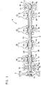
- Fig. 1 is a side view of a camshaft apparatus 1 according to the embodiment of the invention.
- This camshaft apparatus 1 includes a camshaft 2 which is driven to rotate in synchronism with rotation of an engine, a plurality of pairs of cams 3A to 3D which are fitted on an outer circumference of the camshaft 2, and a plurality of rolling bearings 4, 5 which are provided on the outer circumference of the camshaft 2.
- the camshaft 2 is formed to have a single outside diameter throughout its length between opposite end portions thereof.
- the camshaft 2 is supported rotatably in an inner circumferential surface of (support portions of) a shaft case 40 by the plurality of rolling bearings 4, 5.
- a pulley 9 (in this embodiment, a timing pulley to which rotations of the engine are transmitted by a timing belt, and in the case of rotations of the engine being transmitted by a timing chain, a sprocket) is fastened and connected to an outer circumferential surface of one end (a left end in Fig. 1 ) of the camshaft with a bolt 13.
- the pulley 9 is connected to a crankshaft, which is an output shaft (whos.e illustration is omitted) via a timing belt (whose illustration is omitted), so as to rotate in synchronism with the crankshaft, whereby power of the engine is transmitted to the camshaft 2 via the pulley 9.
- the camshaft 2 is made up of an outer circumferential portion 2A and a core portion 2B, and an opening at the other end side (a right end in Fig. 1 ) of the outer circumferential portion 2A is sealed by a bolt 12.
- the camshaft apparatus 1 of this embodiment includes the pairs of cams 3A to 3D, each pair being made up of an inlet cam k and an exhaust cam h, and as is shown in Fig. 1 , the pairs of cams are arranged to be located at predetermined intervals from the one end side to the other end side of the camshaft 2 so as to make up a group of cams.
- An outer circumferential surface configuration of .the end portion of the camshaft 2 to which the pulley 9 is attached is determined in such a manner as not to form any direct contact portion with the inner circumferential of the shaft case 40.
- the restriction flange 102f which is provided at the end portion of the camshaft to which the pulley 109 is provided in the conventional configuration shown in Fig. 4 is eliminated, so as to produce the configuration in which the camshaft 2 is prevented from being brought into direct contact with the shaft case 40.
- the plurality of cams k, h are aligned at predetermined intervals in an axial direction on an outer circumferential surface of the camshaft 2.
- the bearings 4, 5 which support the camshaft 2 rotatably are made up of only rolling bearings.
- the bearings 4, 5 are made up of a single main ball bearing 5 and a plurality of roller bearings 4.
- any of needle rollers, rod rollers and cylindrical rollers which are specified to JIS: B1506 can be adopted as rollers of the roller bearings 4.
- needle rollers are adopted (and hence, hereinafter, the roller bearings 4 will also be referred to as needle roller bearings 4 from time to time). As is shown in Fig.
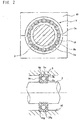
- the main ball bearing 5 is configured as a deep groove ball bearing and has an inner ring 5a which is fixed to the outer circumferential surface of the camshaft 2, an outer ring 5b which is fixed to the inner circumferential surface of the shaft case 40, balls 5c which are disposed in such a manner as to be fitted in groove-shaped raceway-surfaces which are formed on both the inner ring 5a and the outer ring 5b and a cage 5h which regulates intervals at which the balls 5c are arranges in a circumferential direction.
- a cage 5h which regulates intervals at which the balls 5c are arranges in a circumferential direction.
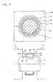
- the needle roller bearings 4 are provided on some of a plurality of inter-cam outer circumferential surface areas 2Q which are formed by partitioning the outer circumferential surface of the camshaft 2 by the plurality of cams k, h.
- Each needle roller bearing 4 has, as is shown in Fig. 3 , an outer ring 4b which is fitted in the inner circumferential surface of the shaft case 40, a raceway surface formed on an inner circumferential surface of the outer ring 4b, needle rollers 4c which are disposed in such a manner as to contact the corresponding inter-cam outer circumferential surface area 2Q of the camshaft 2, and a cage 4h which restricts intervals at which the needle rollers 4c are arranged in a circumferential direction.
- the needle rollers 4c are provided on every other inter-cam outer circumferential surface area 2Q of the plurality of inter-cam outer circumferential surface areas 2Q.
- a configuration results in which the inter-cam outer circumferential surface areas 2Q' where no bearings are provided and the inter-cam outer circumferential surface areas 2Q where the bearings are provided are arranged alternately.
- the bearings which support the camshaft 2 rotatably are made up of only the rolling bearings 5, 4, a reduction in torque when the engine is running at low speeds, a reduction in vibration of the camshaft 2 and an extension of the lives of the bearings can be realized. In addition, even though the camshaft 2 stops rotating, the camshaft 2 does not fall, and hence, a reduction in starting torque can be realized.
- one of the rolling bearings is made to constitute the main ball bearing 5 which restrains an axial relative movement of the camshaft 2 relative to the shaft case 40, and the other rolling rollers are made to constitute the plurality of needle roller bearings 4.
- the mechanical movement of the camshaft 2 in the axial direction can be restricted in an ensured fashion by the main ball bearing 5, while as to the relative displacement between the camshaft 2 and the shaft case 40 due to thermal expansion or contraction of the camshaft 2 and/or the shaft case 40, the axial relative displacement can be absorbed through relative sliding movement of the needle rollers 4c on the inter-cam outer circumferential surface areas 2Q.
- the needle roller bearings 4 are made difficult to be affected by the relative displacement between the camshaft 2 and the shaft case 40 that would otherwise appear remarkably.
- the camshaft 2 is made of a steel material such as a. non-heat treated steel, while the shaft case 40 is made of an aluminum alloy.
- a linear expansion coefficient from the room temperature to a temperature of the order of 300°C of the camshaft 2 is 12 to 13 (x 10 -6 /K), while the same linear expansion coefficient of the shaft case 40 is 30 to 33 (x 10 -6 /K), the former showing a value which is larger by two to three times than the latter. Consequently, of the camshaft 2 and the shaft case 40 which are disposed on the periphery of the engine, when heated up, the shaft case 40 extends more than the camshaft 2.
- an outer circumferential edge portion of the outer ring 5b of the main ball bearing 5 is fixed in such a manner as to be fitted in a circumferentially annular groove 40g formed on the inner circumferential surface of the shaft case 40, whereby the effect of restraining the axial displacement of the camshaft 2 is increased largely.
- the main ball bearing 5 can be provided between the pulley 9 and the cam of the plurality of cams k, h which lies closest to the pulley 9.
- the main ball bearing 5 is such as to form a restraining point relative to the camshaft 2 which restrains the axial relative displacement thereof, and the camshaft 2 displaces relative to the shaft case 40 in such a manner as to contract towards the main ball bearing 5 when heated up, while the camshaft 2 displaces relative to the shaft case 40 in such a manner as to extend to move away from the main ball bearing 5 when cooled down.
- the camshaft 2 displaces relative to the shaft case 40 in such a manner as to extend to move away from the main ball bearing 5 when cooled down.
- a main part (a part lying further rightwards than the main ball bearing 5) of the camshaft 2 is supported by the plurality of needle roller bearings 4, and even though the camshaft 2 extends or contracts in the axial direction relative to the shaft case 40 as has been described above, the aforesaid relative displacements can effectively be absorbed through relative sliding movement of the needle rollers 4c on the inter-cam outer circumferential surface areas 2Q. As a result, it becomes possible to prevent the occurrence of drawbacks such as an increase in torque due to an increase in rotational sliding resistance and an eccentric wear of the raceway surfaces.
- circumferential roller restriction flanges 4bf, 4bf are formed at axial ends of the outer ring 4b in such a manner as to project radially inwards, and axial gaps of a certain amount (that is, an axial play of the roller) are formed respectively between the needle roller 4c and the roller restriction flanges 4bf, 4bf.
- the needle roller bearing 4 can absorb the relative displace between the camshaft 2 and the shaft case 40 by the axial gaps so formed.
- the needle roller bearing 4 is disposed on the inter-cam outer circumferential surface area 2Q in such a manner as to produce axial displacement absorbing gaps CL relatively between the cams k, h which define the inter-cam outer circumferential surface area 2Q and the outer ring 4b.
- a portion which lies axially farther from the main ball bearing 5 which constitutes the displacement restraining point (that is, a portion which lies closer to the right end portion of the camshaft 2 as viewed in Fig. 1 ) tends to have a larger displacement amount associated with thermal expansion or contraction of the camshaft 2.
- the axial displacement absorbing gaps CL which are defined between the cams k, h and the outer ring 4b are set to such a magnitude that the relative displacement amount at the portion of the camshaft which corresponds to the needle roller bearing 4 lying farthest away from the main ball bearing 5 in Fig. 1 can be absorbed sufficiently.
- the camshaft 2 is made integral along the axial direction in such a manner as not to be divided while having a uniform outside diameter at axial sections at each of which the pair of cams k, h are aligned.
- the plurality of cams k, h are made up of sintered members which are shrink fitted on the camshaft 2 (when shrink fitted, the sintered members which make up the cams k, h are heated so as to be expanded diametrically).
- the outer ring 4b of the needle roller bearing 4 is formed in such a manner as not to be divided in a radial direction.
- the inner ring 5a of the main ball bearing 5 which is made of a steel material which has been subjected to quenching and tempering treatments is fitted on.the.outer circumferential surface of the camshaft 2 through cold or warm press fit.
- an auxiliary ball bearing 6 which has an inner ring 6a which is fixed to the outer circumferential surface of the camshaft 2, an outer ring 6b which is provided in such a manner as to enable an axial relative sliding displacement relative to the inner circumferential surface of the shaft case 40, and balls which are disposed in such a manner as to be fitted in groove-shaped raceway surfaces which are formed both on the inner ring 6a and the outer ring 6b.
- the auxiliary ball bearing 6 permits an axial relative sliding displacement of the outer ring 6b relative to the inner circumferential surface of the shaft case 40, the influences from thermal expansion or contraction of the camshaft 2 and/or the shaft case 40 can be absorbed without any problem.
- the auxiliary ball bearing 6 is also made as a deep groove ball bearing and is provided at an opposite end portion of the camshaft 2 to the end portion thereof to which the pulley 9 is attached.
- the length of a cantilever portion of the camshaft 2 is made small which extends further in an opposite direction to where the main ball bearing 5 is positioned than the auxiliary ball bearing 6.
- the outer ring 6b is fitted in the shaft case 40 through clearance fit or press fit in which a radial press fitting margin is made smaller than the outer ring 4b of the needle roller bearing 4.
Landscapes
- Engineering & Computer Science (AREA)
- General Engineering & Computer Science (AREA)
- Mechanical Engineering (AREA)
- Rolling Contact Bearings (AREA)
- Valve-Gear Or Valve Arrangements (AREA)
Description
- The present invention relates to a camshaft apparatus which is driven to rotate in synchronism with rotation of an engine, and more particularly to a camshaft apparatus which is supported ro.tatably by rolling bearings.
- Generally, as an example of a bearing construction for supporting a camshaft rotatably in a shaft case, there has been known a slide bearing construction in which an outer circumferential surface of a
camshaft 102 is supported directly byslide bearings 104 of ashaft case 140 as shown inFig. 4 . In this case, however, since the outer circumferential surface of thecamshaft 102 is brought into direct contact with the bearingportions 104, there is caused a problem of short life or generation of vibration. In addition, as is shown inFig. 5 , in the slide bearing 104, when thecamshaft 102 stops rotating, thecamshaft 102 falls to rest on the bearing side and is then brought into line contact with the slide bearing 104 to thereby increase friction therebetween. This then causes a problem that the increased friction will results in a remarkable torque increase when the engine is started or is running at low speeds. Further, since the slide bearing 104 permits the axial relative slide of thecamshaft 102, a restriction flange 102f is formed at an end portion of thecamshaft 102 which lies at an end to which apulley 109 is attached in such a manner as to be brought into sliding contact with theshaft case 140, so as to restrict the axial movement of thecamshaft 102. However, in this bearing construction, the sliding friction between the restriction flange 102f and theshaft case 140 becomes large, leading to a drawback that the torque loss becomes large. - With a view to avoiding the problems,
JP-A-2006-226183 camshaft 102 is provided. As a result, the pulley-side restriction flange which slide contacts the shaft case can be eliminated from the camshaft, this also contributing to reduction in rotational sliding friction of the camshaft. - In recent years, with a view to reducing the weight of an engine and its peripheral portions, a.configuration has widely been adopted in which a shaft case is made of light metal such as an aluminum alloy. On the other hand, since the camshaft is a component used in a power transmission system, the camshaft is made of a steel material in order to ensure strength and durability. However, the periphery of the engine where the camshaft is disposed tends to be heated to high temperatures and is frequently subjected to thermal cycling occurring in association with start and stop of the engine. In this case, there exists a large difference in linear expansion coefficient between the shaft case to which the outer rings of the ball bearings are fixed and the steel material to which the inner rings of the ball bearings are fixed. Due to the portion where the camshaft is disposed being heated to high temperatures and subjected to thermal cycling, the axial relative displacement of the camshaft relative to the shaft case becomes large considerably. However, since the plurality of bearings which support the camshaft are made up of the ball bearings, the thermal relative displacement between the camshaft and the shaft case is retrained strongly. As a result, an undesirable strong preload is imparted to the ball bearings in the axial direction, whereby an increase in torque tends to be called for easily due to an increase in rotational sliding resistance, and an eccentric wear of the raceway surfaces tends to be produced easily.
-
FR 2 889 568 A - Finally, a further camshaft device is shown in
EP 1860 338 A1 , particularly in Fig. 11 of this document. - An object to be achieved by the invention is to provide a camshaft apparatus which can reduce largely rotational torque of a camshaft, particularly, the rotational torque when an engine is started or is running at low speeds while restricting an axial movement of the camshaft and which is made difficult to be subjected to the influence of the difference in linear expansion coefficient between the camshaft and a shaft case.
- According to the invention, the object is solved by the features of the claim.
- According to the camshaft apparatus of the invention, since the bearings which support the camshaft rotatably are made up of the rolling bearings, a reduction in torque when the engine is running at low speeds, a reduction in vibration of the camshaft and an extension of in life of the bearings can be realized. In addition, even when the camshaft stops rotating, the camshaft does not fall, and hence, a reduction in starting torque can be reduced. Additionally, one of those rolling bearings is made to constitute the main ball bearing for restraining the axial relative movement of the camshaft relative to the shaft case, and the remaining rolling bearings are made to constitute the plurality of roller bearings. By this configuration, the mechanical movement of the camshaft in the axial direction can be restricted in an ensured fashion by the main ball bearing, and the relative displacement between the camshaft and the shaft case due to the thermal extension or contraction thereof can be absorbed by the relative slide movement of the rollers on the inter-cam outer circumferential surface areas, whereby the camshaft apparatus is made difficult to be influenced by the relative displacement between the camshaft and the shaft case due to the thermal extension or contraction thereof.
- Since the camshaft is made up of a material having a different linear expansion coefficient from that of the shaft case (e.g. the former is made of a steel material and the latter is made of a light metal material such as aluminum or an aluminum alloy), the axial relative movement of the camshaft relative to the shaft case due to the difference in linear expansion coefficient between the camshaft and the shaft case tends to become large easily. However, by adopting the configuration of the invention, the aforesaid relative displacement can effectively be absorbed by the relative sliding movement of the rollers on the inter-cam outer circumferential surface areas. This enables the avoidance of impartation of an undesirable axial preload to the bearings due to the thermal factors, thereby making it possible to prevent an increase in torque due to an increase in rotational sliding resistance and generation of a drawback such as an eccentric wear of the raceway surfaces.
- The main ball bearing is such as to form an axial displacement restraining point relative to the camshaft. In the camshaft, a displacement amount in association with thermal expansion or contraction becomes larger as a portion lies farther away from the displacement restraining point in the axial direction, and the displacement amount is made to be absorbed by the sliding displacement within the roller bearings. An outer circumferential edge portion of the outer ring of the main ball bearing is fixed in such a manner as to fit in the circumferential annular groove formed on the inner circumferential surface of the shaft case, whereby the effect of restraining the axial displacement of the camshaft can be increased largely. In addition, the main ball bearing is provided on the camshaft in the position lying between the pulley and the cam of the plurality of cams which is situated closest to the pulley. By this configuration, a belt tension the camshaft would otherwise receive from the pulley side can be received in an ensured fashion by the main ball bearing, and the mechanical displacement of the camshaft in the axial direction can be restricted in an ensured fashion that would occur, should the belt tension be transmitted to the camshaft.
- The roller bearing can absorb the relative displacement between the camshaft and the shaft case by axial gaps defined between the outer ring thereof and the rollers. However, in the event that the rolling bearing is provided on the inter-cam outer circumferential surface in the position lying between the cams which define the inter-cam outer circumferential surface area and the outer ring thereof in such a manner as to produce axial displacement absorbing gaps, even though a relative displacement is produced which-exceeds the axial gap amount of the rolling bearing itself, the relative displacement so produced can be absorbed without any problem.
- The camshaft is made integral in the axial direction in such a manner as not to be divided while having a uniform outside diameter at axial sections where the plurality of cams are aligned, and the plurality of cams are made up of sintered members which are shrink fitted on the camshaft. By adopting this configuration, the shrink fitting of the cam on to the camshaft and the insertion of the camshaft into the roller bearing are performed alternately, the fabrication of the camshaft apparatus can be implemented without any problem, and outer rings which are formed in such a manner as not to be divided in a radial direction can be used for the outer rings of the rollerbearings. By adopting this configuration, compared with the embodiment described in
JP-A-2005-90696 - In the invention, although the roller bearings and the main ball bearing can be provided on all the plurality of inter-cam outer circumferential surfaces, by all the bearings being made up of the rolling bearings, the rotational sliding friction of the bearings can be reduced, as a result of which the load carrying capacity of the individual bearings is increased. As a result, even though a certain number of rolling bearings are thinned out, the load from the camshaft can be borne by the remaining roller bearings or roller bearings provided sufficiently. As this occurs, a configuration can be adopted in which the roller bearings are provided on only part of the plurality of inter-cam outer circumferential surface areas, and by adopting this configuration, the production costs can be decreased by decreasing the number of bearings and the overall weight of the camshaft apparatus can be reduced. As this occurs, there are provided the inter-cam outer circumferential surface areas where no bearing is provided. For example, by providing the roller bearings on every other inter-cam outer circumferential surface area in the plurality of inter-cam outer circumferential surface areas, the total number of roller bearings provided can be decreased substantially to a half a total number of roller bearings which results when they are provided on every inter-cam outer circumferential surface area (as this occurs, a configuration results in which the inter-cam outer circumferential surface area where no bearing is provided and the inter-cam outer circumferential surface area where the bearing is provided are arranged alternately).
- In addition, an auxiliary ball bearing is provided which includes an inner ring which is fixed to the outer circumferential surface of the camshaft, an outer ring which is provided in such a manner as to enable its axial relative sliding displacement relative to the inner circumferential surface of the shaft case and balls which are disposed in such a manner as to fit in groove-shaped raceway surfaces formed on both the inner ring and the outer ring. By providing the auxiliary ball bearing, the load carrying capacity of the camshaft can be increased. In addition, being different from the main ball bearing, the auxiliary ball bearing permits an axial relative sliding displacement of the outer ring relative to the inner circumferential surface of the shaft case, the effect of thermal expansion or contraction of the camshaft and/or the shaft case can be absorbed without any problem. Since the main ball bearing is provided on the camshaft in the position lying between the pulley and the cam of the plurality of cams which is situated closest to the pulley, the auxiliary ball bearing can be provided at an opposite end portion of the camshaft to the end portion lying at the-end to which the pulley is attached. This can function to reduce the length of a cantilever portion of the auxiliary ball bearing which extends towards the opposite end to the end to which the pulley is attached, thereby making it possible to prevent the application of an excessive bending load to the camshaft.
-
-
Fig. 1 is a side view of a camshaft apparatus according to an embodiment of the invention. -
Fig. 2 is an enlarged explanatory view of a main ball bearing. -
Fig. 3 is an enlarged explanatory view of a needle roller bearing. -
Fig. 4 is an explanatory view of a conventional camshaft apparatus which adopts a slide bearing. -
Fig. 5 is a view explaining a problem inherent in the slide bearing. - An embodiment of the invention will be described below with reference to the drawings.
-
Fig. 1 is a side view of a camshaft apparatus 1 according to the embodiment of the invention. This camshaft apparatus 1 includes acamshaft 2 which is driven to rotate in synchronism with rotation of an engine, a plurality of pairs ofcams 3A to 3D which are fitted on an outer circumference of thecamshaft 2, and a plurality ofrolling bearings camshaft 2. In these components, thecamshaft 2 is formed to have a single outside diameter throughout its length between opposite end portions thereof. Thecamshaft 2 is supported rotatably in an inner circumferential surface of (support portions of) ashaft case 40 by the plurality ofrolling bearings Fig. 1 ) of the camshaft with abolt 13. In addition, thepulley 9 is connected to a crankshaft, which is an output shaft (whos.e illustration is omitted) via a timing belt (whose illustration is omitted), so as to rotate in synchronism with the crankshaft, whereby power of the engine is transmitted to thecamshaft 2 via thepulley 9. Thecamshaft 2 is made up of an outercircumferential portion 2A and acore portion 2B, and an opening at the other end side (a right end inFig. 1 ) of the outercircumferential portion 2A is sealed by abolt 12. In addition, the camshaft apparatus 1 of this embodiment includes the pairs ofcams 3A to 3D, each pair being made up of an inlet cam k and an exhaust cam h, and as is shown inFig. 1 , the pairs of cams are arranged to be located at predetermined intervals from the one end side to the other end side of thecamshaft 2 so as to make up a group of cams. - An outer circumferential surface configuration of .the end portion of the
camshaft 2 to which thepulley 9 is attached is determined in such a manner as not to form any direct contact portion with the inner circumferential of theshaft case 40. Specifically, the restriction flange 102f which is provided at the end portion of the camshaft to which thepulley 109 is provided in the conventional configuration shown inFig. 4 is eliminated, so as to produce the configuration in which thecamshaft 2 is prevented from being brought into direct contact with theshaft case 40. - The plurality of cams k, h are aligned at predetermined intervals in an axial direction on an outer circumferential surface of the
camshaft 2. In addition, thebearings camshaft 2 rotatably are made up of only rolling bearings. Specifically, thebearings main ball bearing 5 and a plurality ofroller bearings 4. In addition, in the invention, any of needle rollers, rod rollers and cylindrical rollers which are specified to JIS: B1506 can be adopted as rollers of theroller bearings 4. In this embodiment, however, needle rollers are adopted (and hence, hereinafter, theroller bearings 4 will also be referred to asneedle roller bearings 4 from time to time). As is shown inFig. 2 , themain ball bearing 5 is configured as a deep groove ball bearing and has aninner ring 5a which is fixed to the outer circumferential surface of thecamshaft 2, anouter ring 5b which is fixed to the inner circumferential surface of theshaft case 40,balls 5c which are disposed in such a manner as to be fitted in groove-shaped raceway-surfaces which are formed on both theinner ring 5a and theouter ring 5b and acage 5h which regulates intervals at which theballs 5c are arranges in a circumferential direction. In addition, as is shown inFig. 1 , theneedle roller bearings 4 are provided on some of a plurality of inter-cam outercircumferential surface areas 2Q which are formed by partitioning the outer circumferential surface of thecamshaft 2 by the plurality of cams k, h. Eachneedle roller bearing 4 has, as is shown inFig. 3 , anouter ring 4b which is fitted in the inner circumferential surface of theshaft case 40, a raceway surface formed on an inner circumferential surface of theouter ring 4b,needle rollers 4c which are disposed in such a manner as to contact the corresponding inter-cam outercircumferential surface area 2Q of thecamshaft 2, and acage 4h which restricts intervals at which theneedle rollers 4c are arranged in a circumferential direction. Specifically, theneedle rollers 4c are provided on every other inter-cam outercircumferential surface area 2Q of the plurality of inter-cam outercircumferential surface areas 2Q. As a result, a configuration results in which the inter-cam outercircumferential surface areas 2Q' where no bearings are provided and the inter-cam outercircumferential surface areas 2Q where the bearings are provided are arranged alternately. - According to the camshaft apparatus that has been described above, since the bearings which support the
camshaft 2 rotatably are made up of only the rollingbearings camshaft 2 and an extension of the lives of the bearings can be realized. In addition, even though thecamshaft 2 stops rotating, thecamshaft 2 does not fall, and hence, a reduction in starting torque can be realized. Additionally, one of the rolling bearings is made to constitute themain ball bearing 5 which restrains an axial relative movement of thecamshaft 2 relative to theshaft case 40, and the other rolling rollers are made to constitute the plurality ofneedle roller bearings 4. By adopting this configuration, the mechanical movement of thecamshaft 2 in the axial direction can be restricted in an ensured fashion by themain ball bearing 5, while as to the relative displacement between thecamshaft 2 and theshaft case 40 due to thermal expansion or contraction of thecamshaft 2 and/or theshaft case 40, the axial relative displacement can be absorbed through relative sliding movement of theneedle rollers 4c on the inter-cam outercircumferential surface areas 2Q. Thus, theneedle roller bearings 4 are made difficult to be affected by the relative displacement between thecamshaft 2 and theshaft case 40 that would otherwise appear remarkably. Further, since the restriction flange is eliminated to produce the configuration in which thecamshaft 2 and theshaft case 40 are prevented from being brought into sliding contact with each other, no sliding friction is generated between thecamshaft 2 and theshaft case 40, this also contributing to the suppression of increase in torque. - The
camshaft 2 is made of a steel material such as a. non-heat treated steel, while theshaft case 40 is made of an aluminum alloy. A linear expansion coefficient from the room temperature to a temperature of the order of 300°C of thecamshaft 2 is 12 to 13 (x 10-6/K), while the same linear expansion coefficient of theshaft case 40 is 30 to 33 (x 10-6/K), the former showing a value which is larger by two to three times than the latter. Consequently, of thecamshaft 2 and theshaft case 40 which are disposed on the periphery of the engine, when heated up, theshaft case 40 extends more than thecamshaft 2. In other words, describing this phenomenon based on theshaft case 40 side, it can be said that thecamshaft 2 contracts relative to theshaft case 40. On the contrary, when cooled down, theshaft case 40 contracts more than thecamshaft 2. Similarly, describing this phenomenon based on theshaft case 40 side, it can be said that thecamshaft 2 extends relative to theshaft case 40. In either case, the axial relative displacement of thecamshaft 2 relative to theshaft case 40 due to the difference in linear expansion coefficient therebetween tends to become larger with change in temperature. - Specifically, an outer circumferential edge portion of the
outer ring 5b of themain ball bearing 5 is fixed in such a manner as to be fitted in a circumferentiallyannular groove 40g formed on the inner circumferential surface of theshaft case 40, whereby the effect of restraining the axial displacement of thecamshaft 2 is increased largely. In addition, themain ball bearing 5 can be provided between thepulley 9 and the cam of the plurality of cams k, h which lies closest to thepulley 9. By adopting this configuration, a belt tension thecamshaft 2 would otherwise receive from thepulley 9 side can be received in an ensured fashion by themain ball bearing 5, thereby making it possible to restrict the mechanical displacement of thecamshaft 2 in the axial direction that would otherwise occur in association with application of the belt tension to thecamshaft 2. - As has been described above, the
main ball bearing 5 is such as to form a restraining point relative to thecamshaft 2 which restrains the axial relative displacement thereof, and thecamshaft 2 displaces relative to theshaft case 40 in such a manner as to contract towards themain ball bearing 5 when heated up, while thecamshaft 2 displaces relative to theshaft case 40 in such a manner as to extend to move away from themain ball bearing 5 when cooled down. However, inFig. 1 , a main part (a part lying further rightwards than the main ball bearing 5) of thecamshaft 2 is supported by the plurality ofneedle roller bearings 4, and even though thecamshaft 2 extends or contracts in the axial direction relative to theshaft case 40 as has been described above, the aforesaid relative displacements can effectively be absorbed through relative sliding movement of theneedle rollers 4c on the inter-cam outercircumferential surface areas 2Q. As a result, it becomes possible to prevent the occurrence of drawbacks such as an increase in torque due to an increase in rotational sliding resistance and an eccentric wear of the raceway surfaces. - As is shown in
Fig. 3 , on theneedle roller bearing 4, circumferential roller restriction flanges 4bf, 4bf are formed at axial ends of theouter ring 4b in such a manner as to project radially inwards, and axial gaps of a certain amount (that is, an axial play of the roller) are formed respectively between theneedle roller 4c and the roller restriction flanges 4bf, 4bf. Theneedle roller bearing 4 can absorb the relative displace between thecamshaft 2 and theshaft case 40 by the axial gaps so formed. However, in the embodiment, theneedle roller bearing 4 is disposed on the inter-cam outercircumferential surface area 2Q in such a manner as to produce axial displacement absorbing gaps CL relatively between the cams k, h which define the inter-cam outercircumferential surface area 2Q and theouter ring 4b. By adopting this configuration, even though a relative displacement occurs which is larger than the relative displacement which can be absorbed by the axial gap amount of theneedle roller bearing 4, the relative displace so occurring is made to be absorbed by the axial displacement absorbing gaps CL without any problem. - On the
camshaft 2, a portion which lies axially farther from themain ball bearing 5 which constitutes the displacement restraining point (that is, a portion which lies closer to the right end portion of thecamshaft 2 as viewed inFig. 1 ) tends to have a larger displacement amount associated with thermal expansion or contraction of thecamshaft 2. The axial displacement absorbing gaps CL which are defined between the cams k, h and theouter ring 4b are set to such a magnitude that the relative displacement amount at the portion of the camshaft which corresponds to theneedle roller bearing 4 lying farthest away from themain ball bearing 5 inFig. 1 can be absorbed sufficiently. - Next, in
Fig. 1 , thecamshaft 2 is made integral along the axial direction in such a manner as not to be divided while having a uniform outside diameter at axial sections at each of which the pair of cams k, h are aligned. In addition, the plurality of cams k, h are made up of sintered members which are shrink fitted on the camshaft 2 (when shrink fitted, the sintered members which make up the cams k, h are heated so as to be expanded diametrically). By adopting this configuration, in the event that the shrink fitting of the cams k, h and the insertion of thecamshaft 2 into theneedle roller bearings 4 are performed alternately, the fabrication of the camshaft apparatus 1 can be implemented without any problem. Consequently, theouter ring 4b of theneedle roller bearing 4 is formed in such a manner as not to be divided in a radial direction. On the other hand, theinner ring 5a of themain ball bearing 5 which is made of a steel material which has been subjected to quenching and tempering treatments is fitted on.the.outer circumferential surface of thecamshaft 2 through cold or warm press fit. - In addition, as is shown by alternate long and short dash lines in
Fig. 1 , separately from themain ball bearing 5, an auxiliary ball bearing 6 is provided which has an inner ring 6a which is fixed to the outer circumferential surface of thecamshaft 2, anouter ring 6b which is provided in such a manner as to enable an axial relative sliding displacement relative to the inner circumferential surface of theshaft case 40, and balls which are disposed in such a manner as to be fitted in groove-shaped raceway surfaces which are formed both on the inner ring 6a and theouter ring 6b. By providing the auxiliary ball bearing 6, the load carrying capacity of thecamshaft 2 can be increased. In addition, being different from themain ball bearing 5, since the auxiliary ball bearing 6 permits an axial relative sliding displacement of theouter ring 6b relative to the inner circumferential surface of theshaft case 40, the influences from thermal expansion or contraction of thecamshaft 2 and/or theshaft case 40 can be absorbed without any problem. InFig. 1 , the auxiliary ball bearing 6 is also made as a deep groove ball bearing and is provided at an opposite end portion of thecamshaft 2 to the end portion thereof to which thepulley 9 is attached. Thus, the length of a cantilever portion of thecamshaft 2 is made small which extends further in an opposite direction to where themain ball bearing 5 is positioned than the auxiliary ball bearing 6. Theouter ring 6b is fitted in theshaft case 40 through clearance fit or press fit in which a radial press fitting margin is made smaller than theouter ring 4b of theneedle roller bearing 4.
Claims (1)
- A camshaft apparatus comprising:a shaft case (40);a camshaft (2) surrounded by the shaft case (40) so as not to contact with the shaft case (40);a pulley (9) attached to the camshaft (2);a plurality of cams (3A-3D) which are aligned on an outer circumferential surface of the camshaft (2) at predetermined intervals in an axial direction to define inter-cam outer circumferential surface areas on the outer circumferential surface between the adjacent cams (3A-3D);a single main ball bearing (5) which includes an inner ring (5a) fixed to the outer circumferential surface of the camshaft (2) and having a groove-shaped raceway surface, an outer ring (5b) fixed to an inner circumferential surface of the shaft case (40) and including a groove-shaped raceway surface, and balls (5c) which are disposed so as to fit in groove-shaped raceway surfaces of the inner (5a) and outer (5b) rings; anda plurality of roller bearings (4) which are disposed in at least part of the inter-cam outer circumferential surface areas, wherein each of the roller bearings (4) includes an outer ring (4b) fitted in the inner circumferential surface of the shaft case (40) and having a raceway surface, and rollers (4c) disposed in such a manner as to be in contact with the raceway surface and the corresponding inter-cam outer circumferential surface area, characterized in that the main ball bearing (5) is provided on the camshaft (2) in the position lying between the pulley (9) and the cam (3A) of the plurality of cams (3A-3D) which is situated closest to the pulley (9),
wherein the camshaft (2) is made of a material having a different linear expansion coefficient from that of the shaft case (40),an axial relative displacement of the camshaft (2) relative to the shaft case (40) due to a difference in the linear expansion coefficient between the camshaft (2) and the shaft case (40) is absorbed by a relative sliding movement of the rollers (4c) on the inter-cam outer circumferential surface areas, andan auxiliary ball bearing (6) which includes an inner ring (6a) which fixed to the outer circumferential surface of the camshaft (2) and including a groove-shaped raceway, an outer ring (6b) which is provided in such a manner as to be allowed to axially slide relative to the inner circumferential surface of the shaft case (40) and includes a groove-shaped raceway, and balls (6c) disposed in such a manner as to fit in the groove-shaped raceway surfaces of the inner ring (6a) and the outer ring (6b) of the auxiliary ball bearing (6).
Applications Claiming Priority (1)
| Application Number | Priority Date | Filing Date | Title |
|---|---|---|---|
| JP2008003542A JP5145953B2 (en) | 2008-01-10 | 2008-01-10 | Camshaft device |
Publications (3)
| Publication Number | Publication Date |
|---|---|
| EP2078829A1 EP2078829A1 (en) | 2009-07-15 |
| EP2078829B1 EP2078829B1 (en) | 2011-03-16 |
| EP2078829B2 true EP2078829B2 (en) | 2020-05-20 |
Family
ID=40578472
Family Applications (1)
| Application Number | Title | Priority Date | Filing Date |
|---|---|---|---|
| EP09000166.0A Active EP2078829B2 (en) | 2008-01-10 | 2009-01-08 | Camshaft apparatus |
Country Status (4)
| Country | Link |
|---|---|
| US (1) | US8051821B2 (en) |
| EP (1) | EP2078829B2 (en) |
| JP (1) | JP5145953B2 (en) |
| DE (1) | DE602009000859D1 (en) |
Families Citing this family (18)
| Publication number | Priority date | Publication date | Assignee | Title |
|---|---|---|---|---|
| JP2006200619A (en) * | 2005-01-20 | 2006-08-03 | Otics Corp | Rotating assembly and its manufacturing method |
| JP5145953B2 (en) † | 2008-01-10 | 2013-02-20 | 株式会社ジェイテクト | Camshaft device |
| DE102009009665A1 (en) * | 2009-02-19 | 2010-08-26 | Mahle International Gmbh | Internal combustion engine with at least one camshaft |
| JP2011099342A (en) * | 2009-11-04 | 2011-05-19 | Jtekt Corp | Camshaft device |
| JP5532872B2 (en) * | 2009-12-01 | 2014-06-25 | 株式会社ジェイテクト | Camshaft device |
| CN101782004B (en) * | 2009-12-09 | 2013-06-05 | 苏州麦格特发动机有限公司 | Camshaft structure arranged on top of diesel engine |
| DE102010005874A1 (en) * | 2010-01-27 | 2011-07-28 | Daimler AG, 70327 | Camshaft with roller bearing, mounting arrangement for a camshaft with roller bearings and method of manufacture |
| DE102010019130B4 (en) * | 2010-04-30 | 2021-02-04 | Mahle International Gmbh | Cylinder head |
| JP5376336B2 (en) * | 2010-04-30 | 2013-12-25 | トヨタ自動車株式会社 | Camshaft intermittent lubrication type rolling bearing device |
| DE102010019129A1 (en) * | 2010-04-30 | 2011-11-03 | Mahle International Gmbh | Bearing block of a camshaft |
| DE102010056111A1 (en) * | 2010-12-23 | 2012-06-28 | Neumayer Tekfor Holding Gmbh | Bearing structure for cam shaft used for controlling valve of combustion engine, has ball bearing that is provided in one of bearing points provided in bearing bridge for receiving cam shafts |
| DE102011011803A1 (en) * | 2011-02-19 | 2012-08-23 | Volkswagen Ag | Actuation module for at least one gas exchange valve of an internal combustion engine |
| DE102011081486A1 (en) * | 2011-08-24 | 2013-02-28 | Mahle International Gmbh | crankcase |
| DE102011088655A1 (en) * | 2011-12-15 | 2013-06-20 | Schaeffler Technologies AG & Co. KG | Rolling bearing for a built camshaft |
| DE102012217456A1 (en) * | 2012-09-26 | 2014-03-27 | Mahle International Gmbh | Camshaft for an internal combustion engine |
| DE102013203842A1 (en) | 2013-03-06 | 2014-09-11 | Mahle International Gmbh | bearing arrangement |
| DE102013207200A1 (en) * | 2013-04-22 | 2014-11-06 | Mahle International Gmbh | Internal combustion engine |
| DE102019214289A1 (en) * | 2019-09-19 | 2021-03-25 | Volkswagen Aktiengesellschaft | Camshaft assembly for a motor vehicle and method for assembling a camshaft assembly |
Citations (6)
| Publication number | Priority date | Publication date | Assignee | Title |
|---|---|---|---|---|
| DE3526029A1 (en) † | 1985-07-20 | 1987-01-29 | Bosch Gmbh Robert | FUEL INJECTION PUMP FOR INTERNAL COMBUSTION ENGINES |
| JPH08284617A (en) † | 1995-04-18 | 1996-10-29 | Suzuki Motor Corp | Camshaft bearing structure for multicylinder four-cycle engine |
| US5826461A (en) † | 1996-01-22 | 1998-10-27 | Kaywood Products Corporation | Camshaft assembly and method of making the same |
| WO2007016913A2 (en) † | 2005-08-05 | 2007-02-15 | Neumayer Tekfor Holding Gmbh | Shaft comprising functional elements, such as a camshaft for use in internal combustion engines, method for producing said shafts, and internal combustion engines equipped therewith |
| EP1860338A1 (en) † | 2005-03-11 | 2007-11-28 | JTEKT Corporation | Rolling bearing, camshaft device, and camshaft supporting device |
| EP2078829A1 (en) † | 2008-01-10 | 2009-07-15 | JTEKT Corporation | Camshaft apparatus |
Family Cites Families (20)
| Publication number | Priority date | Publication date | Assignee | Title |
|---|---|---|---|---|
| JPS593121Y2 (en) * | 1977-09-30 | 1984-01-28 | ダイハツ工業株式会社 | Camshaft bearing device in internal combustion engine |
| JPS5935637U (en) * | 1982-08-31 | 1984-03-06 | スズキ株式会社 | Mounting structure of intermediate shaft for overhead cam drive |
| JPS5949706U (en) * | 1982-09-27 | 1984-04-02 | 本田技研工業株式会社 | Internal combustion engine camshaft bearing device |
| US5218883A (en) * | 1988-02-07 | 1993-06-15 | Mannesmann Aktiengesellschaft | Assembled shaft and process for production thereof |
| JPH0648082Y2 (en) * | 1988-06-16 | 1994-12-07 | 川崎重工業株式会社 | Axial play removal device for camshaft |
| JPH03275907A (en) * | 1990-03-23 | 1991-12-06 | Mazda Motor Corp | Manufacture of camshaft |
| JPH03275908A (en) * | 1990-03-26 | 1991-12-06 | Mazda Motor Corp | Camshaft and manufacture thereof |
| JP2927360B2 (en) * | 1990-04-27 | 1999-07-28 | エヌティエヌ株式会社 | Cam shaft support mechanism |
| US5209194A (en) * | 1991-04-26 | 1993-05-11 | Nippondenso Co., Ltd. | Variable valve timing apparatus |
| DE4307562B4 (en) * | 1993-03-10 | 2004-04-01 | Bayerische Motoren Werke Ag | Process for manufacturing a sintered control cam that can be positioned on a control shaft by thermal shrinking |
| JPH08128306A (en) * | 1994-11-02 | 1996-05-21 | Suzuki Motor Corp | Camshaft structure for engine |
| JP3862462B2 (en) * | 2000-01-20 | 2006-12-27 | 本田技研工業株式会社 | Cam follower drop-off prevention structure |
| JP4134587B2 (en) * | 2001-04-16 | 2008-08-20 | スズキ株式会社 | Valve operating device and internal combustion engine provided with the same |
| JP2005090696A (en) | 2003-09-19 | 2005-04-07 | Nsk Ltd | Roller bearing and internal combustion engine |
| JP2006226183A (en) * | 2005-02-17 | 2006-08-31 | Jtekt Corp | Camshaft device and its assembling method |
| JP2006226400A (en) | 2005-02-17 | 2006-08-31 | Jtekt Corp | Shaft device |
| JP2006226184A (en) * | 2005-02-17 | 2006-08-31 | Jtekt Corp | Camshaft device and its assembling method |
| JP4400484B2 (en) * | 2005-03-11 | 2010-01-20 | 株式会社ジェイテクト | Camshaft support device |
| US20070232427A1 (en) * | 2006-03-29 | 2007-10-04 | Jtekt Corporation | Pulley assembly and pulley usable therefor |
| FR2901571B1 (en) * | 2006-05-29 | 2013-07-26 | Peugeot Citroen Automobiles Sa | SYSTEM FOR MOUNTING A CAMSHAFT PROVIDED WITH BEARINGS |
-
2008
- 2008-01-10 JP JP2008003542A patent/JP5145953B2/en active Active
-
2009
- 2009-01-08 EP EP09000166.0A patent/EP2078829B2/en active Active
- 2009-01-08 DE DE602009000859T patent/DE602009000859D1/en active Active
- 2009-01-09 US US12/318,839 patent/US8051821B2/en active Active
Patent Citations (6)
| Publication number | Priority date | Publication date | Assignee | Title |
|---|---|---|---|---|
| DE3526029A1 (en) † | 1985-07-20 | 1987-01-29 | Bosch Gmbh Robert | FUEL INJECTION PUMP FOR INTERNAL COMBUSTION ENGINES |
| JPH08284617A (en) † | 1995-04-18 | 1996-10-29 | Suzuki Motor Corp | Camshaft bearing structure for multicylinder four-cycle engine |
| US5826461A (en) † | 1996-01-22 | 1998-10-27 | Kaywood Products Corporation | Camshaft assembly and method of making the same |
| EP1860338A1 (en) † | 2005-03-11 | 2007-11-28 | JTEKT Corporation | Rolling bearing, camshaft device, and camshaft supporting device |
| WO2007016913A2 (en) † | 2005-08-05 | 2007-02-15 | Neumayer Tekfor Holding Gmbh | Shaft comprising functional elements, such as a camshaft for use in internal combustion engines, method for producing said shafts, and internal combustion engines equipped therewith |
| EP2078829A1 (en) † | 2008-01-10 | 2009-07-15 | JTEKT Corporation | Camshaft apparatus |
Also Published As
| Publication number | Publication date |
|---|---|
| US8051821B2 (en) | 2011-11-08 |
| EP2078829B1 (en) | 2011-03-16 |
| DE602009000859D1 (en) | 2011-04-28 |
| JP5145953B2 (en) | 2013-02-20 |
| US20090178630A1 (en) | 2009-07-16 |
| EP2078829A1 (en) | 2009-07-15 |
| JP2009167807A (en) | 2009-07-30 |
Similar Documents
| Publication | Publication Date | Title |
|---|---|---|
| EP2078829B2 (en) | Camshaft apparatus | |
| CA2539595C (en) | Self-aligning antifriction bearing and cage for said self-aligning antifriction bearing | |
| EP2302241B1 (en) | Shaft apparatus with roller bearing | |
| US8715123B2 (en) | Rotation urging mechanism and pulley device | |
| WO2010018821A1 (en) | Variable valve timing device | |
| EP1507089B1 (en) | Self-aligning bearing | |
| US20120174882A1 (en) | Camshaft apparatus | |
| EP1262686B1 (en) | Pulley unit having one-way clutch | |
| US11965549B2 (en) | Unbalanced shaft | |
| EP2806181A1 (en) | Rotation transmission device with built-in one-way clutch and alternator comprising such a device | |
| US20190226535A1 (en) | Clutch device | |
| US20050064977A1 (en) | Roller/retainer assembly for planetary gear and planetary gears support using the same | |
| US10533607B2 (en) | Cage for radial roller bearing | |
| JP4893997B2 (en) | One-way clutch | |
| JP6610871B2 (en) | Pulley structure using double-row six-point contact ball bearings | |
| JP7229009B2 (en) | pulley unit | |
| US20170102025A1 (en) | Piston machine | |
| JPH09264156A (en) | Crankshaft supporting structure for 2-cycle engine | |
| JP2004211880A (en) | Pulley unit | |
| JP2007327609A (en) | Divided type roller bearing | |
| JP4228178B2 (en) | Water pump bearing | |
| JP2008164034A (en) | One-way clutch and one-way clutch unit | |
| JP2007085398A (en) | One-way clutch built-in type pulley device | |
| JP4457582B2 (en) | One-way clutch built-in pulley device | |
| JP2004204891A (en) | Bearing for water pump |
Legal Events
| Date | Code | Title | Description |
|---|---|---|---|
| PUAI | Public reference made under article 153(3) epc to a published international application that has entered the european phase |
Free format text: ORIGINAL CODE: 0009012 |
|
| AK | Designated contracting states |
Kind code of ref document: A1 Designated state(s): AT BE BG CH CY CZ DE DK EE ES FI FR GB GR HR HU IE IS IT LI LT LU LV MC MK MT NL NO PL PT RO SE SI SK TR |
|
| AX | Request for extension of the european patent |
Extension state: AL BA RS |
|
| 17P | Request for examination filed |
Effective date: 20091029 |
|
| AKX | Designation fees paid |
Designated state(s): DE FR |
|
| GRAP | Despatch of communication of intention to grant a patent |
Free format text: ORIGINAL CODE: EPIDOSNIGR1 |
|
| GRAS | Grant fee paid |
Free format text: ORIGINAL CODE: EPIDOSNIGR3 |
|
| GRAA | (expected) grant |
Free format text: ORIGINAL CODE: 0009210 |
|
| AK | Designated contracting states |
Kind code of ref document: B1 Designated state(s): DE FR |
|
| REF | Corresponds to: |
Ref document number: 602009000859 Country of ref document: DE Date of ref document: 20110428 Kind code of ref document: P |
|
| REG | Reference to a national code |
Ref country code: DE Ref legal event code: R096 Ref document number: 602009000859 Country of ref document: DE Effective date: 20110428 |
|
| PLBI | Opposition filed |
Free format text: ORIGINAL CODE: 0009260 |
|
| PLAX | Notice of opposition and request to file observation + time limit sent |
Free format text: ORIGINAL CODE: EPIDOSNOBS2 |
|
| 26 | Opposition filed |
Opponent name: THYSSENKRUPP PRESTA TECCENTER AG Effective date: 20111216 |
|
| REG | Reference to a national code |
Ref country code: DE Ref legal event code: R026 Ref document number: 602009000859 Country of ref document: DE Effective date: 20111216 |
|
| PLBB | Reply of patent proprietor to notice(s) of opposition received |
Free format text: ORIGINAL CODE: EPIDOSNOBS3 |
|
| RDAF | Communication despatched that patent is revoked |
Free format text: ORIGINAL CODE: EPIDOSNREV1 |
|
| APBM | Appeal reference recorded |
Free format text: ORIGINAL CODE: EPIDOSNREFNO |
|
| APBP | Date of receipt of notice of appeal recorded |
Free format text: ORIGINAL CODE: EPIDOSNNOA2O |
|
| APAH | Appeal reference modified |
Free format text: ORIGINAL CODE: EPIDOSCREFNO |
|
| APBQ | Date of receipt of statement of grounds of appeal recorded |
Free format text: ORIGINAL CODE: EPIDOSNNOA3O |
|
| REG | Reference to a national code |
Ref country code: FR Ref legal event code: PLFP Year of fee payment: 8 |
|
| PLAB | Opposition data, opponent's data or that of the opponent's representative modified |
Free format text: ORIGINAL CODE: 0009299OPPO |
|
| R26 | Opposition filed (corrected) |
Opponent name: THYSSENKRUPP PRESTA TECCENTER AG Effective date: 20111216 |
|
| REG | Reference to a national code |
Ref country code: FR Ref legal event code: PLFP Year of fee payment: 9 |
|
| REG | Reference to a national code |
Ref country code: FR Ref legal event code: PLFP Year of fee payment: 10 |
|
| PLAB | Opposition data, opponent's data or that of the opponent's representative modified |
Free format text: ORIGINAL CODE: 0009299OPPO |
|
| R26 | Opposition filed (corrected) |
Opponent name: THYSSENKRUPP PRESTA TECCENTER AG Effective date: 20111216 |
|
| APBU | Appeal procedure closed |
Free format text: ORIGINAL CODE: EPIDOSNNOA9O |
|
| PUAH | Patent maintained in amended form |
Free format text: ORIGINAL CODE: 0009272 |
|
| STAA | Information on the status of an ep patent application or granted ep patent |
Free format text: STATUS: PATENT MAINTAINED AS AMENDED |
|
| 27A | Patent maintained in amended form |
Effective date: 20200520 |
|
| AK | Designated contracting states |
Kind code of ref document: B2 Designated state(s): DE FR |
|
| REG | Reference to a national code |
Ref country code: DE Ref legal event code: R102 Ref document number: 602009000859 Country of ref document: DE |
|
| PGFP | Annual fee paid to national office [announced via postgrant information from national office to epo] |
Ref country code: DE Payment date: 20221130 Year of fee payment: 15 |
|
| PGFP | Annual fee paid to national office [announced via postgrant information from national office to epo] |
Ref country code: FR Payment date: 20231212 Year of fee payment: 16 |