EP2078583B1 - Mechanical device for assembling and/or disassembling a laser nozzle and laser processing machine with such a device - Google Patents
Mechanical device for assembling and/or disassembling a laser nozzle and laser processing machine with such a device Download PDFInfo
- Publication number
- EP2078583B1 EP2078583B1 EP08000520A EP08000520A EP2078583B1 EP 2078583 B1 EP2078583 B1 EP 2078583B1 EP 08000520 A EP08000520 A EP 08000520A EP 08000520 A EP08000520 A EP 08000520A EP 2078583 B1 EP2078583 B1 EP 2078583B1
- Authority
- EP
- European Patent Office
- Prior art keywords
- nozzle
- lifting
- nozzle holder
- holder
- carrier
- Prior art date
- Legal status (The legal status is an assumption and is not a legal conclusion. Google has not performed a legal analysis and makes no representation as to the accuracy of the status listed.)
- Active
Links
- 239000002184 metal Substances 0.000 claims abstract description 4
- 229910052751 metal Inorganic materials 0.000 claims abstract description 4
- 150000002739 metals Chemical class 0.000 abstract 1
- 230000033001 locomotion Effects 0.000 description 8
- 238000005520 cutting process Methods 0.000 description 4
- 230000005540 biological transmission Effects 0.000 description 1
- 238000011109 contamination Methods 0.000 description 1
- 230000008878 coupling Effects 0.000 description 1
- 238000010168 coupling process Methods 0.000 description 1
- 238000005859 coupling reaction Methods 0.000 description 1
- 230000001419 dependent effect Effects 0.000 description 1
- 230000005484 gravity Effects 0.000 description 1
- 238000009434 installation Methods 0.000 description 1
- 238000003698 laser cutting Methods 0.000 description 1
- 238000003754 machining Methods 0.000 description 1
- 239000000463 material Substances 0.000 description 1
- 239000002245 particle Substances 0.000 description 1
- 239000002893 slag Substances 0.000 description 1
Images


Classifications
-
- B—PERFORMING OPERATIONS; TRANSPORTING
- B23—MACHINE TOOLS; METAL-WORKING NOT OTHERWISE PROVIDED FOR
- B23K—SOLDERING OR UNSOLDERING; WELDING; CLADDING OR PLATING BY SOLDERING OR WELDING; CUTTING BY APPLYING HEAT LOCALLY, e.g. FLAME CUTTING; WORKING BY LASER BEAM
- B23K26/00—Working by laser beam, e.g. welding, cutting or boring
- B23K26/14—Working by laser beam, e.g. welding, cutting or boring using a fluid stream, e.g. a jet of gas, in conjunction with the laser beam; Nozzles therefor
- B23K26/1462—Nozzles; Features related to nozzles
- B23K26/1482—Detachable nozzles, e.g. exchangeable or provided with breakaway lines
-
- B—PERFORMING OPERATIONS; TRANSPORTING
- B23—MACHINE TOOLS; METAL-WORKING NOT OTHERWISE PROVIDED FOR
- B23K—SOLDERING OR UNSOLDERING; WELDING; CLADDING OR PLATING BY SOLDERING OR WELDING; CUTTING BY APPLYING HEAT LOCALLY, e.g. FLAME CUTTING; WORKING BY LASER BEAM
- B23K26/00—Working by laser beam, e.g. welding, cutting or boring
- B23K26/14—Working by laser beam, e.g. welding, cutting or boring using a fluid stream, e.g. a jet of gas, in conjunction with the laser beam; Nozzles therefor
- B23K26/1462—Nozzles; Features related to nozzles
- B23K26/1494—Maintenance of nozzles
-
- B—PERFORMING OPERATIONS; TRANSPORTING
- B23—MACHINE TOOLS; METAL-WORKING NOT OTHERWISE PROVIDED FOR
- B23K—SOLDERING OR UNSOLDERING; WELDING; CLADDING OR PLATING BY SOLDERING OR WELDING; CUTTING BY APPLYING HEAT LOCALLY, e.g. FLAME CUTTING; WORKING BY LASER BEAM
- B23K26/00—Working by laser beam, e.g. welding, cutting or boring
- B23K26/70—Auxiliary operations or equipment
- B23K26/702—Auxiliary equipment
-
- Y—GENERAL TAGGING OF NEW TECHNOLOGICAL DEVELOPMENTS; GENERAL TAGGING OF CROSS-SECTIONAL TECHNOLOGIES SPANNING OVER SEVERAL SECTIONS OF THE IPC; TECHNICAL SUBJECTS COVERED BY FORMER USPC CROSS-REFERENCE ART COLLECTIONS [XRACs] AND DIGESTS
- Y10—TECHNICAL SUBJECTS COVERED BY FORMER USPC
- Y10T—TECHNICAL SUBJECTS COVERED BY FORMER US CLASSIFICATION
- Y10T483/00—Tool changing
- Y10T483/17—Tool changing including machine tool or component
-
- Y—GENERAL TAGGING OF NEW TECHNOLOGICAL DEVELOPMENTS; GENERAL TAGGING OF CROSS-SECTIONAL TECHNOLOGIES SPANNING OVER SEVERAL SECTIONS OF THE IPC; TECHNICAL SUBJECTS COVERED BY FORMER USPC CROSS-REFERENCE ART COLLECTIONS [XRACs] AND DIGESTS
- Y10—TECHNICAL SUBJECTS COVERED BY FORMER USPC
- Y10T—TECHNICAL SUBJECTS COVERED BY FORMER US CLASSIFICATION
- Y10T483/00—Tool changing
- Y10T483/18—Tool transfer to or from matrix
- Y10T483/1873—Indexing matrix
Definitions
- JP 06 023580 A discloses a machine nozzle changing device which is mounted on a laser processing machine on top of a horizontal workpiece table.
- a nozzle magazine designed as a revolver magazine of the nozzle changing device comprises a magazine turret, which can be rotated about a vertical turret rotation axis.
- Mounted on the magazine turret are a plurality of nozzle holders spaced apart in the direction of rotation about the turret rotation axis. These are used to hold each, a laser nozzle, as it comes to a laser processing head of the prior art machine used.
- the workpiece table of the laser processing machine and the laser processing head are moved relative to each other in the horizontal direction until the laser processing head with the laser nozzle to be replaced lies above an empty nozzle holder of the nozzle magazine of the nozzle changing device. Subsequently, the laser processing head is lowered toward the nozzle changing device. In this case, the laser nozzle to be dismantled comes to lie in the interior of the previously empty nozzle holder. By appropriate rotational movement of the nozzle holder, the laser nozzle is then unscrewed from a nozzle holder of the laser processing head.
- the magazine turret of the nozzle changing device and the laser processing head of the prior art machine are moved relative to each other until the nozzle holder of the nozzle magazine occupied with the laser nozzle to be mounted faces the nozzle holder on the laser processing head in the vertical direction. Lowering the laser processing head, the new laser nozzle is then screwed into the nozzle holder on the laser processing head.
- a flexibly arrangeable device for mounting and / or dismantling laser nozzles and provided with such an arrangement To provide a laser processing machine, the present invention has set itself starting from the described prior art.
- the assembly and / or disassembly device according to the invention offers the possibility of delivering nozzle holders, for example when changing nozzles, in two directions running transverse to one another. In both directions, the nozzle holder (s) of the device can be positioned opposite the nozzle holder of a laser processing machine. Due to the positionability of the nozzle holder or the location of the device according to the invention for mounting and / or disassembly of laser nozzles can be flexibly choose without the required for the nozzle assembly or - dismantling mutual accessibility of the nozzle holder and machine-side nozzle holder would be affected.
- the nozzle holder movement is realized on the one hand by means of the claimed carrier feed drive and on the other hand by means of the lifting device according to the invention.
- the carrier feed drive positions the nozzle holder carrier as well as the nozzle holder (s) mounted thereon in the carrier feed direction.
- the lifting device serves to move the nozzle holder or nozzles relative to the nozzle holder carrier in the transverse direction of the carrier feed direction.
- the claims 2 to 5 relate to invention types, which are characterized by a structurally simple and functionally reliable design of the lifting device for the nozzle holder or holders.
- the opposite the nozzle holder carrier in delivery stroke direction raised nozzle holder perform an assembly or dismantling rotational movement and thereby in particular a laser nozzle on the nozzle holder of a laser processing machine on or unscrew.
- the lifting element of the lifting device for the nozzle holder used as a transmission element of the rotary drive, by means of which delivered in the delivery stroke direction nozzle holder can drive in the assembly direction of rotation and / or in the disassembly direction of rotation.
- the nozzle magazine of the mechanical device for mounting and / or disassembling of laser nozzles is designed as a revolver magazine on which a magazine turret supports the nozzle holder (s) (claim 8).
- This invention type is characterized by a particularly compact design.
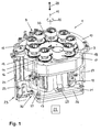
- a nozzle changing device 1 shown in the figures serves as a machine device for mounting and / or dismantling laser nozzles 2 on a nozzle holder 3, which in turn is provided on a laser processing head 4 of a laser processing machine 5. evidenced FIG. 4 At the laser processing machine 5 during normal operation, a sheet 6 is cut by means of a laser cutting beam 7.
- the nozzle changing device 1 comprises a nozzle magazine designed as a revolver magazine 8.
- a magazine turret 9 acting as a nozzle holder carrier is rotatably mounted on a housing 10 of the nozzle changing device 1 about a turret rotation axis 11.
- nozzle holders 12 are inserted into the magazine turret 9.
- a shaft-like lifting element 13 is mounted, which projects towards the lunts over the magazine turret 9 and the has a different cross-section of the circular shape.
- planetary gears 14 are each rotatably mounted about a gear axis of rotation 15. The gear rotation axes 15 simultaneously form nozzle holder axes of rotation.
- the planet gears 14 each have an inner recess 16, at which they are penetrated by the shaft-like lifting element 13 of the respective nozzle holder 12 in the vertical direction.
- a so-called "blind station” 17 with a hollow-cylinder-like passage 18 is provided on the magazine turret 9 of the revolving magazine 8.
- the nozzle changing device 1 on the laser processing machine 5 at least one nozzle holder 12 is covered with a laser nozzle 2 to be mounted on the laser processing head 4.
- the magazine turret 9 can be moved about the turret rotation axis 11 in different rotational positions in a carrier or turret feed direction illustrated by a double arrow 20.
- An essential part of the revolver-Zustellantriebes 19 is an electric revolver-feed motor 21, by means of a in the FIGS. 1 to 3 indicated numerical drive control 22 is controlled.
- the numerical drive control 22 is integrated with the use of the nozzle changing device 1 as part of the laser processing machine 5 in the CNC control.
- the nozzle changing device 1 has a pneumatic lifting drive 23, which in turn comprises a lifting cylinder 24 fixed to the housing 10 of the nozzle changing device 1 and which is likewise controlled by the drive control 22.
- a piston In the interior of the lifting cylinder 24, a piston, not visible in the figures, is movably guided in the vertical direction. Without the interposition of a piston rod, the piston of the pneumatic lifting drive 23 is connected to an intermediate piece 25, which in turn acts on a jack formed as a lifting plate 26.
- the lifting plate 26 is guided on guide rods 27 of the housing 10 of the nozzle changing device 1 in a vertical feed stroke direction (double arrow 28) movable. Between the guide rods 27 an open in revolver feed direction 20 shaft receptacle 29 is provided on the lifting plate 26 for the free end of the attached to the nozzle holders 12 shaft-like Aushebeiata 13.
- the pneumatic lifting drive 23 and the lifting plate 26 and the lifting elements 13 are part of a lifting device 30 for the nozzle holder 12th
- FIG. 1 illustrated operating state of the nozzle changing device 1 is associated with the regular operation of the laser processing machine 5.
- the blind station 17 with the hollow-cylinder-like passage 18 is located above the shaft receptacle 29 provided on the lifting plate 26 of the lifting device 30.
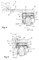
- the nozzle changing device 1 according to the FIGS. 4 to 6 arranged on the underside of a workpiece support 31 of the laser processing machine 5.
- the laser processing head 4 of the laser processing machine 5 If the laser nozzle 2 mounted on the laser processing head 4 of the laser processing machine 5 is to be exchanged for another laser nozzle 2 due to, for example, a change of the material to be processed, then an interruption of the regular cutting operation of the laser processing machine 5 will initially be provided on the workpiece support 31 of the laser processing machine 5 Ausschleusklappe 33 from the closed state according to FIG. 4 open. Subsequently, the laser processing head 4 on the one hand and the workpiece support 31 with the nozzle changing device 1 on the other hand relative to each other in the horizontal direction moves until the laser processing head 4 comes to rest with the laser nozzle 2 to be replaced via the passage opening 32 of the workpiece support 31.
- the turret feed motor 21 of the nozzle changing device 1 is actuated. Controlled by the drive control 22, the turret feed motor 21 moves the magazine turret 9 of the nozzle changing device 1 in the turret feed direction 20 over a defined angle of rotation.
- the magazine turret 9 is drivingly connected via a not shown in detail switchable coupling with the turret feed motor 21.
- the advancing movement of the magazine turret 9 ends as soon as an empty nozzle holder 12, which follows the blind station 17 in the direction of rotation, in the hub standby position according to FIG. 2 arrives.
- the empty nozzle holder 12 is above the shaft receptacle 29 on the lifting plate 26 of the lifting device 30.
- the on the empty nozzle holder 12 provided shaft-like lifting element 13 is run with its free lower end into the shaft receptacle 29 on the lifting plate 26 and is engaged behind by the lifting plate 26 at the side remote from the nozzle holder 12 side.
- the empty nozzle holder 12 is located below the passage opening 32 of the workpiece support 31 and thereby the laser nozzle 2 to be dismantled in the delivery stroke direction 28.
- the lifting drive 23 is actuated controlled by the drive control 22.
- the lifting plate 26 of the lifting device 30 moves upward, lifting the empty nozzle holder 12 out of its bearing on the magazine turret 9 of the revolving magazine 8 via the shaft-like lifting element 13.
- the laser nozzle 2 reaches the laser processing head 4 in the interior of the nozzle holder 12.
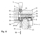
- the nozzle changing device 1 is in the operating state according to FIG. 3 , In FIG. 3
- the planet gears 14 are different from the FIGS. 1 and 2 provided with a cover.
- the switching device not shown in detail the turret feed motor 21.
- the turret feed motor 21 is set in motion and drives via a mounted on a motor shaft 34 sun gear 35 to the now rotatably fixed magazine turret 9 rotatably mounted planetary gears 14 about the gear axes of rotation 15.
- Rotary operation is particular also that planet gear 14, which is penetrated by the shaft-like lifting element 13 on the upwardly excavated nozzle holder 12. Due to the corresponding geometries of the inner recess 16 of the planetary gear 14 on the one hand and the cross section of the upward lifting Aushebeimplantations 13 on the other hand, the lifting element 13 is taken by the planetary gear 14 in its direction of rotation.
- the nozzle holder 12 arranged on the laser nozzle 2 to be dismantled is driven via the associated planet gear 14 and the shaft-like lifting element 13 attached thereto in a dismantling direction of rotation.
- the nozzle holder 12 takes the laser nozzle 2 received by it in disassembly rotational direction and the laser nozzle 2 mounted on the laser processing head 4 is unscrewed from the nozzle holder 3 of the laser processing head 4.
- the laser nozzle 2 Under resilient support via the nozzle holder 12, the laser nozzle 2 can lower in the Ausschraubvorgang down.
- the uncoupled from the magazine turret 9 turret feed motor 21, the sun gear 35, the respective planet gear 14 and driven by this shaft-like lifting element 13 form a rotary drive 36 for the nozzle holder 12th
- the lifting drive 23 of the nozzle changing device 1 is actuated again.
- the lifting plate 26 of the lifting device 30 is lowered in the delivery stroke direction 28 to its original position.
- the stocked with the used laser nozzle 2 nozzle holder 12 is then stored again on the magazine turret 9 of the revolver magazine 8.
- the lifting device 30 makes it possible to perform nozzle changes on the laser processing machine 5 even when arranged below the workpiece support 31 nozzle changing device 1. In this respect, the lifting device ensures 30 a particular flexibility in the choice of the installation location of the nozzle changing device. 1
- the turret feed motor 21 is actuated and thereby the magazine turret 9 delivered in the turret feed direction 20 until a nozzle holder 12 arrives with a laser nozzle 2 to be mounted on the laser processing head 4 in the hub standby position.
- the lifting drive 23 is actuated.
- the magazine turret 9 is again coupled to the turret feed motor 21, the blind station 17 with the hollow-cylinder-like passage 18 via the shaft receptacle is actuated by actuating the turret feed motor 21 29 is rotated on the lifting plate 26 of the lifting device 30.
- the nozzle changing device 1 is now again in the operating state according to FIG. 1 , At the laser processing machine 5, the regular cutting operation can be resumed.
Abstract
Description
Die Erfindung betrifft eine maschinelle Vorrichtung zur Montage und/oder zur Demontage einer Laserdüse an einer Düsenaufnahme einer Laserbearbeitungsmaschine zum Bearbeiten von Werkstücken, insbesondere von Blechen,
- mit einem Düsenmagazin mit einem Düsenhalterträger,
- mit einem Düsenhalter für eine Laserdüse, der an dem Düsenhalterträger des Düsenmagazins gelagert ist sowie
- mit einem Träger-Zustellantrieb, mittels dessen der Düsenhalterträger gemeinsam mit dem Düsenhalter in einer Träger-Zustellrichtung zustellbar ist.
- with a nozzle magazine with a nozzle holder carrier,
- with a nozzle holder for a laser nozzle, which is mounted on the nozzle holder carrier of the nozzle magazine and
- with a carrier feed drive, by means of which the nozzle holder carrier is deliverable together with the nozzle holder in a carrier feed direction.
Gattungsgemäßer Stand der Technik ist bekannt aus
Zum Düsenwechsel an dem Laserbearbeitungskopf werden der Werkstücktisch der Laserbearbeitungsmaschine und der Laserbearbeitungskopf relativ zueinander in horizontaler Richtung bewegt, bis der Laserbearbeitungskopf mit der auszuwechselnden Laserdüse oberhalb eines leeren Düsenhalters des Düsenmagazins der Düsenwechselvorrichtung liegt. Anschließend wird der Laserbearbeitungskopf zu der Düsenwechselvorrichtung hin abgesenkt. Dabei kommt die zu demontierende Laserdüse im Innern des zuvor leeren Düsenhalters zu liegen. Durch entsprechende Drehbewegung des Düsenhalters wird dann die Laserdüse aus einer Düsenaufnahme des Laserbearbeitungskopfes ausgeschraubt. Nach der Demontage der gebrauchten Laserdüse werden der Magazinrevolver der Düsenwechselvorrichtung und der Laserbearbeitungskopf der vorbekannten Maschine relativ zueinander bewegt, bis der mit der zu montierenden Laserdüse belegte Düsenhalter des Düsenmagazins der Düsenaufnahme an dem Laserbearbeitungskopf in vertikaler Richtung gegenüberliegt. Unter Absenken des Laserbearbeitungskopfes wird dann die neue Laserdüse in die Düsenaufnahme an dem Laserbearbeitungskopf eingeschraubt.For changing nozzles on the laser processing head, the workpiece table of the laser processing machine and the laser processing head are moved relative to each other in the horizontal direction until the laser processing head with the laser nozzle to be replaced lies above an empty nozzle holder of the nozzle magazine of the nozzle changing device. Subsequently, the laser processing head is lowered toward the nozzle changing device. In this case, the laser nozzle to be dismantled comes to lie in the interior of the previously empty nozzle holder. By appropriate rotational movement of the nozzle holder, the laser nozzle is then unscrewed from a nozzle holder of the laser processing head. After disassembling the used laser nozzle, the magazine turret of the nozzle changing device and the laser processing head of the prior art machine are moved relative to each other until the nozzle holder of the nozzle magazine occupied with the laser nozzle to be mounted faces the nozzle holder on the laser processing head in the vertical direction. Lowering the laser processing head, the new laser nozzle is then screwed into the nozzle holder on the laser processing head.
Eine flexibel anordenbare Vorrichtung zur Montage und/oder zur Demontage von Laserdüsen sowie eine mit einer derartigen Anordnung versehene Laserbearbeitungsmaschine bereitzustellen, hat sich die vorliegende Erfindung ausgehend von dem beschriebenen Stand der Technik zum Ziel gesetzt.A flexibly arrangeable device for mounting and / or dismantling laser nozzles and provided with such an arrangement To provide a laser processing machine, the present invention has set itself starting from the described prior art.
Erfindungsgemäß gelöst wird diese Aufgabe durch die maschinelle Vorrichtung gemäß Patentanspruch 1 sowie durch die Laserbearbeitungsmaschine gemäß Patentanspruch 9.This object is achieved according to the invention by the mechanical device according to
Die erfindungsgemäße Montage- und/oder Demontagevorrichtung bietet die Möglichkeit, Düsenhalter beispielsweise beim Düsenwechsel in zwei quer zueinander verlaufenden Richtungen zuzustellen. In beiden Richtungen können der oder die Düsenhalter der Vorrichtung gegenüber der Düsenaufnahme einer Laserbearbeitungsmaschine positioniert werden. Aufgrund der Positionierbarkeit des oder der Düsenhalter lässt sich der Einbauort der erfindungsgemäßen Vorrichtung zur Montage und/oder zur Demontage von Laserdüsen flexibel wählen, ohne dass die für die Düsenmontage bzw. - demontage erforderliche gegenseitige Zugänglichkeit von Düsenhalter und maschinenseitiger Düsenaufnahme beeinträchtigt wäre. Realisiert wird die Düsenhalterbewegung zum einen mittels des anspruchsgemäßen Träger-Zustellantriebes und zum andern mittels der erfindungsgemäßen Hubvorrichtung. Der Träger-Zustellantrieb positioniert den Düsenhalterträger sowie den oder die daran gelagerten Düsenhalter in der Träger-Zustellrichtung. Die Hubvorrichtung dient dazu, den oder die Düsenhalter gegenüber dem Düsenhalterträger in Querrichtung der Träger-Zustellrichtung zu bewegen.The assembly and / or disassembly device according to the invention offers the possibility of delivering nozzle holders, for example when changing nozzles, in two directions running transverse to one another. In both directions, the nozzle holder (s) of the device can be positioned opposite the nozzle holder of a laser processing machine. Due to the positionability of the nozzle holder or the location of the device according to the invention for mounting and / or disassembly of laser nozzles can be flexibly choose without the required for the nozzle assembly or - dismantling mutual accessibility of the nozzle holder and machine-side nozzle holder would be affected. The nozzle holder movement is realized on the one hand by means of the claimed carrier feed drive and on the other hand by means of the lifting device according to the invention. The carrier feed drive positions the nozzle holder carrier as well as the nozzle holder (s) mounted thereon in the carrier feed direction. The lifting device serves to move the nozzle holder or nozzles relative to the nozzle holder carrier in the transverse direction of the carrier feed direction.
Besondere Ausführungsarten der Erfindung gemäß den Patentansprüchen 1 und 9 ergeben sich aus den abhängigen Patentansprüchen 2 bis 8.Particular embodiments of the invention according to the
Die Patentansprüche 2 bis 5 betreffen Erfindungsbauarten, die sich durch eine konstruktiv einfache und funktionssichere Bauweise der Hubvorrichtung für den oder die Düsenhalter auszeichnen.The
Gemäß Patentanspruch 6 ist in bevorzugter Ausgestaltung der Erfindung vorgesehen, dass der gegenüber dem Düsenhalterträger in Zustell-Hubrichtung angehobene Düsenhalter eine Montage- oder eine Demontagedrehbewegung ausführen und dadurch eine Laserdüse an der Düsenaufnahme einer Laserbearbeitungsmaschine insbesondere ein- oder ausschrauben kann.According to
In bevorzugter Ausgestaltung der Erfindung wird ausweislich Patentanspruch 7 das Aushebeelement der Hubvorrichtung für den Düsenhalter als Getriebeelement des Drehantriebes verwendet, mittels dessen sich der in der Zustell-Hubrichtung zugestellte Düsenhalter in der Montage-Drehrichtung und/oder in der Demontage-Drehrichtung antreiben lässt.In a preferred embodiment of the invention is evidently claim 7, the lifting element of the lifting device for the nozzle holder used as a transmission element of the rotary drive, by means of which delivered in the delivery stroke direction nozzle holder can drive in the assembly direction of rotation and / or in the disassembly direction of rotation.
Im Falle einer weiteren bevorzugten Ausführungsform der Erfindung ist das Düsenmagazin der maschinellen Vorrichtung zur Montage und/oder zur Demontage von Laserdüsen als Revolvermagazin ausgebildet, an welchem ein Magazinrevolver den oder die Düsenhalter lagert (Patentanspruch 8). Diese Erfindungsbauart zeichnet sich durch eine besonders kompakte Bauweise aus.In the case of a further preferred embodiment of the invention, the nozzle magazine of the mechanical device for mounting and / or disassembling of laser nozzles is designed as a revolver magazine on which a magazine turret supports the nozzle holder (s) (claim 8). This invention type is characterized by a particularly compact design.
Nachfolgend wird die Erfindung anhand beispielhafter schematischer Darstellungen näher erläutert. Es zeigen:
- Fig. 1
- eine maschinelle Düsenwechselvorrichtung mit einem als Revolvermagazin ausgebildeten Düsenmagazin, dessen Magazinrevolver eine erste Drehstellung einnimmt,
- Fig. 2
- die Anordnung gemäß
Figur 1 - Fig. 3
- die Anordnung gemäß
Figur 2 - Fig. 4
- eine stark schematisierte Darstellung einer Laserbearbeitungsmaschine mit der maschinellen Düsenwechselvorrichtung gemäß
Figur 1 - Fig. 5
- die Anordnung gemäß
Figur 4 mit der maschinellen Düsenwechselvorrichtung gemäßFigur 2 - Fig. 6
- die Anordnung gemäß
Figur 5Figur 3
- Fig. 1
- a machine nozzle changing device with a nozzle magazine designed as a revolver magazine whose magazine turret assumes a first rotational position,
- Fig. 2
- the arrangement according to
FIG. 1 with a second rotational position of the magazine turret, - Fig. 3
- the arrangement according to
FIG. 2 with a nozzle holder excavated from the magazine turret, - Fig. 4
- a highly schematic representation of a laser processing machine with the mechanical nozzle changing device according to
FIG. 1 . - Fig. 5
- the arrangement according to
FIG. 4 with the mechanical nozzle changing device according toFIG. 2 and - Fig. 6
- the arrangement according to
FIG. 5 with the mechanical nozzle changing device according toFIG. 3 ,
Eine in den Abbildungen dargestellte Düsenwechselvorrichtung 1 dient als maschinelle Vorrichtung zur Montage und/oder zur Demontage von Laserdüsen 2 an einer Düsenaufnahme 3, die ihrerseits an einem Laserbearbeitungskopf 4 einer Laserbearbeitungsmaschine 5 vorgesehen ist. Ausweislich
Die Düsenwechselvorrichtung 1 umfasst ein als Revolvermagazin 8 ausgebildetes Düsenmagazin. Ein als Düsenhalterträger fungierender Magazinrevolver 9 ist an einem Gehäuse 10 der Düsenwechselvorrichtung 1 um eine Revolver-Drehachse 11 drehbar gelagert.The
Mehrere Düsenhalter 12 sind in den Magazinrevolver 9 eingesetzt. An jedem der Düsenhalter 12 ist ein schaftartiges Aushebeelement 13 angebracht, das nach lunten hin über den Magazinrevolver 9 vorsteht und das einen von der Kreisform abweichenden Querschnitt besitzt. An der Oberseite des Magazinrevolvers 9 sind Planeten-Zahnräder 14 jeweils um eine Zahnrad-Drehachse 15 drehbar gelagert. Die Zahnrad-Drehachsen 15 bilden gleichzeitig Düsenhalter-Drehachsen aus.
Die Planeten-Zahnräder 14 besitzen jeweils eine Innenaussparung 16, an welcher sie von dem schaftartigen Aushebeelement 13 des betreffenden Düsenhalters 12 in vertikaler Richtung durchsetzt werden. Zusätzlich zu den Düsenhaltern 12 ist an dem Magazinrevolver 9 des Revolvermagazins 8 eine so genannte "Blindstation" 17 mit einem hohlzylinderartigen Durchlass 18 vorgesehen. Der Einfachheit halber sind in den
Mittels eines Träger- bzw. Revolver-Zustellantriebes 19 kann der Magazinrevolver 9 in einer durch einen Doppelpfeil 20 veranschaulichten Träger- bzw. Revolver-Zustellrichtung um die Revolver-Drehachse 11 in unterschiedliche Drehstellungen bewegt werden. Wesentlicher Bestandteil des Revolver-Zustellantriebes 19 ist ein elektrischer Revolver-Zustellmotor 21, der mittels einer in den
Zusätzlich zu dem Revolver-Zustellantrieb 19 verfügt die Düsenwechselvorrichtung 1 über einen pneumatischen Hubantrieb 23, der seinerseits einen an dem Gehäuse 10 der Düsenwechselvorrichtung 1 befestigten Hubzylinder 24 umfasst und der gleichfalls von der Antriebssteuerung 22 gesteuert wird.In addition to the
Im Innern des Hubzylinders 24 ist ein in den Abbildungen nicht sichtbarer Kolben in vertikaler Richtung beweglich geführt. Ohne Zwischenschaltung einer Kolbenstange ist der Kolben des pneumatischen Hubantriebes 23 mit einem Zwischenstück 25 verbunden, das seinerseits an einem als Hubplatte 26 ausgebildeten Heber angreift. Die Hubplatte 26 ist an Führungsstangen 27 des Gehäuses 10 der Düsenwechselvorrichtung 1 in einer vertikalen Zustell-Hubrichtung (Doppelpfeil 28) bewegbar geführt. Zwischen den Führungsstangen 27 ist an der Hubplatte 26 eine in Revolver-Zustellrichtung 20 offene Schaftaufnahme 29 für das freie Ende der an den Düsenhaltern 12 angebrachten schaftartigen Aushebeelemente 13 vorgesehen. Ebenso wie der pneumatische Hubantrieb 23 sind auch die Hubplatte 26 und die Aushebeelemente 13 Teil einer Hubvorrichtung 30 für die Düsenhalter 12.In the interior of the lifting
Der in
An der Laserbearbeitungsmaschine 5 ist die Düsenwechselvorrichtung 1 gemäß den
Bei regulärem Schneidbetrieb der Laserbearbeitungsmaschine 5 und dementsprechend bei dem in
Ist die an dem Laserbearbeitungskopf 4 der Laserbearbeitungsmaschine 5 montierte Laserdüse 2 beispielsweise aufgrund eines Wechsels des zu bearbeitenden Materials oder verschmutzungsbedingt gegen eine andere Laserdüse 2 auszutauschen, so wird während einer Unterbrechung des regulären Schneidbetriebes der Laserbearbeitungsmaschine 5 zunächst eine an der Werkstückauflage 31 der Laserbearbeitungsmaschine 5 vorgesehene Ausschleusklappe 33 aus dem geschlossenen Zustand gemäß
Die Zustellbewegung des Magazinrevolvers 9 endet, sobald ein leerer Düsenhalter 12, welcher auf die Blindstation 17 in Drehrichtung folgt, in die Hub-Bereitschaftsposition gemäß
Die Verhältnisse, die sich an der Laserbearbeitungsmaschine 5 bei dem in
Demnach liegt der leere Düsenhalter 12 unterhalb der Durchtrittsöffnung 32 der Werkstückauflage 31 und dabei der zu demontierenden Laserdüse 2 in Zustell-Hubrichtung 28 gegenüber.Accordingly, the
Ausgehend von diesen Verhältnissen wird der Hubantrieb 23 von der Antriebssteuerung 22 gesteuert betätigt. Die Hubplatte 26 der Hubvorrichtung 30 bewegt sich nach oben und hebt dabei über das schaftartige Aushebeelement 13 den leeren Düsenhalter 12 aus seiner Lagerung an dem Magazinrevolver 9 des Revolvermagazins 8 aus. Infolge der Aufwärtsbewegung des leeren Düsenhalters 12 gelangt die Laserdüse 2 an dem Laserbearbeitungskopf 4 in das Innere des Düsenhalters 12. Es ergibt sich damit die in
Der Revolver-Zustellmotor 21 wird in Gang gesetzt und treibt über ein an einer Motorwelle 34 angebrachtes Sonnen-Zahnrad 35 die an dem nun drehfesten Magazinrevolver 9 drehbar gelagerten Planeten-Zahnräder 14 um die Zahnrad-Drehachsen 15 an. Drehangetrieben wird insbesondere auch dasjenige Planeten-Zahnrad 14, welches von dem schaftartigen Aushebeelement 13 an dem nach oben ausgehobenen Düsenhalter 12 durchsetzt wird. Aufgrund entsprechender Geometrien der Innenaussparung 16 des Planeten-Zahnrades 14 einerseits und des Querschnittes des nach oben bewegten Aushebeelementes 13 andererseits wird das Aushebeelement 13 von dem Planeten-Zahnrad 14 in dessen Drehrichtung mitgenommen.The
Bei entsprechender Drehrichtung des Revolver-Zustellmotors 21 wird der an der zu demontierenden Laserdüse 2 angeordnete Düsenhalter 12 über das zugeordnete Planeten-Zahnrad 14 und das an ihm angebrachte schaftartige Aushebeelement 13 in einer Demontage-Drehrichtung angetrieben. Der Düsenhalter 12 nimmt dabei die von ihm aufgenommene Laserdüse 2 in Demontage-Drehrichtung mit und die an dem Laserbearbeitungskopf 4 montierte Laserdüse 2 wird aus der Düsenaufnahme 3 des Laserbearbeitungskopfes 4 ausgeschraubt. Unter federnder Abstützung über den Düsenhalter 12 kann sich die Laserdüse 2 bei dem Ausschraubvorgang nach unten absenken. Der von dem Magazinrevolver 9 abgekuppelte Revolver-Zustellmotor 21, das Sonnen-Zahnrad 35, das betreffende Planeten-Zahnrad 14 sowie das von diesem angetriebene schaftartige Aushebeelement 13 bilden einen Drehantrieb 36 für den Düsenhalter 12.With a corresponding direction of rotation of the
Ist die auszutauschende Laserdüse 2 demontiert, so wird erneut der Hubantrieb 23 der Düsenwechselvorrichtung 1 betätigt. Die Hubplatte 26 der Hubvorrichtung 30 wird in Zustell-Hubrichtung 28 in ihre Ausgangsposition abgesenkt. Der mit der gebrauchten Laserdüse 2 bestückte Düsenhalter 12 ist dann wieder an dem Magazinrevolver 9 des Revolvermagazins 8 gelagert.If the
Die Hubvorrichtung 30 gestattet es, Düsenwechsel an der Laserbearbeitungsmaschine 5 auch bei unterhalb der Werkstückauflage 31 angeordneter Düsenwechselvorrichtung 1 durchzuführen. Insofern gewährleistet die Hubvorrichtung 30 eine besondere Flexibilität bei der Wahl des Einbauortes der Düsenwechselvorrichtung 1.The lifting
Ist der Düsenhalter 12 mit der gebrauchten Laserdüse 2 in den Magazinrevolver 9 abgesenkt und der Revolver-Zustellmotor 21 erneut an den Magazinrevolver 9 angekuppelt, wird der Revolver-Zustellmotor 21 betätigt und dadurch der Magazinrevolver 9 in der Revolver-Zustellrichtung 20 zugestellt, bis ein Düsenhalter 12 mit einer an dem Laserbearbeitungskopf 4 zu montierenden Laserdüse 2 in die Hub-Bereitschaftsposition gelangt. Unter erneutem Abkuppeln des Revolver-Zustellmotors 21 von dem Magazinrevolver 9 wird wiederum der Hubantrieb 23 betätigt. Über die Hubplatte 26 wird der mit der zu montierenden Laserdüse 2 versehene Düsenhalter 12 in Zustell-Hubrichtung 28 angehoben, bis die zu montierende Laserdüse 2 mit ihrem Gewinde auf dem Gewinde der Düsenaufnahme 3 an dem Laserbearbeitungskopf 4 stirnseitig aufsetzt. In vertikaler Richtung stützt sich die neue Laserdüse 2 dabei unter Federvorspannung auf dem Rand der Düsenaufnahme 3 an dem Laserbearbeitungskopf 4 ab. Wird nun der Revolver-Zustellmotor 21 mit entsprechender Drehrichtung betrieben, so wird über das Sonnen-Zahnrad 35 und das betreffende Planeten-Zahnrad 14 der nach oben angehobene Düsenhalter 12 mit der darin befindlichen Laserdüse 2 in Montage-Drehrichtung bewegt und dadurch die Laserdüse 2 in die Düsenaufnahme 3 des Laserbearbeitungskopfes 4 eingeschraubt.If the
Nach Beendigung des Einschraubvorganges wird der Hubantrieb 23 erneut betätigt und der nun leere Düsenhalter 12 wird zu dem Magazinrevolver 9 hin abgesenkt. Es ergeben sich damit Verhältnisse entsprechend den in Figur 5 dargestellten.After completion of the screwing the lifting
Ist der Magazinrevolver 9 wieder an den Revolver-Zustellmotor 21 angekuppelt, wird durch Betätigen des Revolver-Zustellmotors 21 die Blindstation 17 mit dem hohlzylinderartigen Durchlass 18 über die Schaftaufnahme 29 an der Hubplatte 26 der Hubvorrichtung 30 gedreht. Nach Schließen der Ausschleusklappe 33 und nach einer entsprechenden Relativbewegung von Laserbearbeitungskopf 4 und Werkstückauflage 31 sind die Verhältnisse gemäß
Claims (9)
- Mechanical device for mounting and/or dismounting a laser nozzle (2) at a nozzle mounting (3) of a laser processing machine (5) for processing workpieces, especially metal sheets (6),• having a nozzle magazine (8) with a nozzle holder support (9),• having a nozzle holder (12) for a laser nozzle (2), which nozzle holder (12) is supported on the nozzle holder support (9) of the nozzle magazine (8), and• having a support positioning drive (19) by means of which the nozzle holder support (9) together with the nozzle holder (12) is positionable in a support positioning direction (20),characterised in that
a lifting device (30) is provided by means of which the nozzle holder (12) positioned in a lifting readiness position in the support positioning direction (20) is positionable relative to the nozzle holder support (9) in a positioning lifting direction (28) extending transversely to the support positioning direction (20). - Mechanical device according to claim 1, characterised in that the lifting device (30) includes a lifting-out element (13) via which the nozzle holder (12) can be lifted out of its storage location on the nozzle holder support (9) and positioned in the positioning lifting direction (28) by means of a lifting drive (23) of the lifting device (30).
- Mechanical device according to either of the preceding claims, characterised in that the lifting-out element (13) is of a shank-like configuration.
- Mechanical device according to any one of the preceding claims, characterised in that the lifting-out element (13) is connected to the nozzle holder (12).
- Mechanical device according to any one of the preceding claims, characterised in that the lifting device (30) includes a lifter (26) which engages behind the nozzle holder (12) positioned in the lifting readiness position and which, by means of a lifting drive (23) of the lifting device (30), is positionable in the positioning lifting direction (28) together with the nozzle holder (12) positioned in the lifting readiness position.
- Mechanical device according to any one of the preceding claims, characterised in that the nozzle holder (12) positioned in the positioning lifting direction (28) is drivable by means of a rotary drive (36) about a nozzle holder rotation axis (15) in a mounting rotation direction and/or in a dismounting rotation direction.
- Mechanical device according to any one of the preceding claims, characterised in that the nozzle holder (12) positioned in the positioning lifting direction (28) is drivable about the nozzle holder rotation axis (15) in the mounting rotation direction or in the dismounting rotation direction by means of the rotary drive (36) via the lifting -out element (13) of the lifting device (30).
- Mechanical device according to any one of the preceding claims, characterised in that the nozzle magazine (8) is configured as a turret magazine and as such has a nozzle holder support (9) in the form of a magazine turret which is positionable together with the nozzle holder (12) supported on the magazine turret about a turret rotation axis (11) in the support positioning direction (20) by means of the support positioning drive (19).
- Laser processing machine for processing workpieces, especially metal sheets (6), having a nozzle mounting (3) for a laser nozzle (2), characterised by a mechanical device (1) according to any one of claims 1 to 8 for mounting and/or dismounting a laser nozzle (2) at the nozzle mounting (3).
Priority Applications (7)
| Application Number | Priority Date | Filing Date | Title |
|---|---|---|---|
| AT08000520T ATE464970T1 (en) | 2008-01-12 | 2008-01-12 | MACHINE DEVICE FOR ASSEMBLY AND/OR DISASSEMBLY OF A LASER NOZZLE AND LASER PROCESSING MACHINE WITH SUCH A MACHINE DEVICE |
| DE502008000563T DE502008000563D1 (en) | 2008-01-12 | 2008-01-12 | Mechanical device for mounting and / or dismantling a laser nozzle and laser processing machine with such a machine device |
| DE202008010576U DE202008010576U1 (en) | 2008-01-12 | 2008-01-12 | Mechanical device for mounting and / or dismantling a laser nozzle and laser processing machine with such a machine device |
| EP08000520A EP2078583B1 (en) | 2008-01-12 | 2008-01-12 | Mechanical device for assembling and/or disassembling a laser nozzle and laser processing machine with such a device |
| US12/351,249 US8439811B2 (en) | 2008-01-12 | 2009-01-09 | Laser nozzle changing device |
| CN2009100020682A CN101524807B (en) | 2008-01-12 | 2009-01-12 | Mechanical device mounting/demounting laser nozzle and laser processing machine using the same |
| JP2009004789A JP2009166235A (en) | 2008-01-12 | 2009-01-13 | Mechanical device for replacing laser nozzle and laser processing device with such a mechanical device |
Applications Claiming Priority (1)
| Application Number | Priority Date | Filing Date | Title |
|---|---|---|---|
| EP08000520A EP2078583B1 (en) | 2008-01-12 | 2008-01-12 | Mechanical device for assembling and/or disassembling a laser nozzle and laser processing machine with such a device |
Publications (2)
| Publication Number | Publication Date |
|---|---|
| EP2078583A1 EP2078583A1 (en) | 2009-07-15 |
| EP2078583B1 true EP2078583B1 (en) | 2010-04-21 |
Family
ID=39496157
Family Applications (1)
| Application Number | Title | Priority Date | Filing Date |
|---|---|---|---|
| EP08000520A Active EP2078583B1 (en) | 2008-01-12 | 2008-01-12 | Mechanical device for assembling and/or disassembling a laser nozzle and laser processing machine with such a device |
Country Status (6)
| Country | Link |
|---|---|
| US (1) | US8439811B2 (en) |
| EP (1) | EP2078583B1 (en) |
| JP (1) | JP2009166235A (en) |
| CN (1) | CN101524807B (en) |
| AT (1) | ATE464970T1 (en) |
| DE (1) | DE502008000563D1 (en) |
Families Citing this family (12)
| Publication number | Priority date | Publication date | Assignee | Title |
|---|---|---|---|---|
| EP2078584B1 (en) * | 2008-01-12 | 2010-09-01 | Trumpf Maschinen AG | Mechanical device for assembling and/or disassembling a laser nozzle and laser processing machine with such a device |
| EP2409808A1 (en) * | 2010-07-22 | 2012-01-25 | Bystronic Laser AG | Laser processing machine |
| US9289852B2 (en) | 2011-01-27 | 2016-03-22 | Bystronic Laser Ag | Laser processing machine, laser cutting machine, and method for adjusting a focused laser beam |
| EP2667998B1 (en) | 2011-01-27 | 2020-11-18 | Bystronic Laser AG | Laser processing machine and method for centering a focused laser beam |
| EP2589458B1 (en) * | 2011-11-07 | 2014-08-06 | Trumpf Maschinen AG | Nozzle holder, nozzle changer and laser processing machine |
| EP2883647B1 (en) | 2013-12-12 | 2019-05-29 | Bystronic Laser AG | Method for configuring a laser machining device |
| WO2016103211A1 (en) * | 2014-12-23 | 2016-06-30 | Bystronic Laser Ag | Mount for at least one protective glass, laser machine having such a mount and method for automatically exchanging protective glasses |
| EP3138655B1 (en) * | 2015-09-02 | 2018-08-08 | ASM Technology Singapore Pte Ltd. | Optical station for exchanging optical elements |
| CN109877473A (en) * | 2019-02-27 | 2019-06-14 | 大族激光科技产业集团股份有限公司 | Attaching/detaching apparatus |
| CN110076513B (en) * | 2019-04-22 | 2021-10-08 | 广东美的智能机器人有限公司 | Welding equipment, production line with welding equipment and welding method |
| CN112719612A (en) * | 2020-12-21 | 2021-04-30 | 宁夏苏锡铜业科技有限公司 | Feeding and positioning structure for square copper pipe marking device |
| CN114770143B (en) * | 2022-06-16 | 2022-09-27 | 江苏宏达数控科技股份有限公司 | Gantry type numerical control machining tool |
Family Cites Families (20)
| Publication number | Priority date | Publication date | Assignee | Title |
|---|---|---|---|---|
| NL236924A (en) * | 1958-03-10 | |||
| US3161951A (en) * | 1962-09-17 | 1964-12-22 | Scully Anthony Corp | Automatic tool handling apparatus |
| US3355798A (en) * | 1966-07-27 | 1967-12-05 | Kearney & Trecker Corp | Machine tool with a tool changer |
| JPS5935737B2 (en) * | 1982-04-27 | 1984-08-30 | 東洋精機工業株式会社 | Drill attachment/detachment storage device for drilling presses, etc. |
| FR2547230A1 (en) * | 1983-06-09 | 1984-12-14 | Moulin Georges | Automatic tool-changing device, especially for machine tools |
| US4858290A (en) * | 1986-10-23 | 1989-08-22 | Brother Kogyo Kabushiki Kaisha | Machine tool indexing apparatus |
| JP3038083B2 (en) | 1992-07-09 | 2000-05-08 | 株式会社アマダ | Nozzle changing device in laser beam machine |
| DE10056330C1 (en) | 1999-09-16 | 2002-03-07 | Precitec Kg | Lens holder changing device for laser machining head provides simultaneous replacement of lens holder and further function element held in common storage magazine location |
| JP2002059329A (en) * | 2000-08-23 | 2002-02-26 | Sankyo Mfg Co Ltd | Tool magazine |
| JP2002160085A (en) | 2000-11-14 | 2002-06-04 | Precitec Kg | Exchanging device for lens holder of connecting head for laser beam machining |
| JP3725129B2 (en) | 2003-02-25 | 2005-12-07 | ファナック株式会社 | Automatic tool tip changer for robot |
| DE50303112D1 (en) * | 2003-07-26 | 2006-06-01 | Trumpf Werkzeugmaschinen Gmbh | Machine tool with tool lifting drive |
| JP2005334921A (en) | 2004-05-26 | 2005-12-08 | Yamazaki Mazak Corp | Nozzle-changing magazine in laser beam machine |
| JP2005334926A (en) * | 2004-05-26 | 2005-12-08 | Yamazaki Mazak Corp | Nozzle presetter of laser beam machining tool in laser beam machine |
| JP2005334920A (en) | 2004-05-26 | 2005-12-08 | Yamazaki Mazak Corp | Tool-changing magazine in laser beam machine |
| DE102005028358A1 (en) * | 2005-06-18 | 2006-12-21 | Alfing Keßler Sondermaschinen GmbH | Processing machine arrangement with robot and tool magazine |
| ITMI20050232U1 (en) * | 2005-06-24 | 2006-12-25 | Busellato S P A | AUTOMATIC TOOL CHANGE DEVICE |
| JP5026027B2 (en) * | 2006-08-29 | 2012-09-12 | ヤマザキマザック株式会社 | Automatic tool changer for laser processing machines |
| EP2078584B1 (en) * | 2008-01-12 | 2010-09-01 | Trumpf Maschinen AG | Mechanical device for assembling and/or disassembling a laser nozzle and laser processing machine with such a device |
| EP2078586B1 (en) * | 2008-01-12 | 2011-01-12 | TRUMPF Werkzeugmaschinen GmbH + Co. KG | Laser processing machine with device for nozzle swapping |
-
2008
- 2008-01-12 AT AT08000520T patent/ATE464970T1/en active
- 2008-01-12 DE DE502008000563T patent/DE502008000563D1/en active Active
- 2008-01-12 EP EP08000520A patent/EP2078583B1/en active Active
-
2009
- 2009-01-09 US US12/351,249 patent/US8439811B2/en active Active
- 2009-01-12 CN CN2009100020682A patent/CN101524807B/en active Active
- 2009-01-13 JP JP2009004789A patent/JP2009166235A/en active Pending
Also Published As
| Publication number | Publication date |
|---|---|
| CN101524807B (en) | 2013-05-15 |
| DE502008000563D1 (en) | 2010-06-02 |
| CN101524807A (en) | 2009-09-09 |
| EP2078583A1 (en) | 2009-07-15 |
| JP2009166235A (en) | 2009-07-30 |
| ATE464970T1 (en) | 2010-05-15 |
| US8439811B2 (en) | 2013-05-14 |
| US20090179018A1 (en) | 2009-07-16 |
Similar Documents
| Publication | Publication Date | Title |
|---|---|---|
| EP2078583B1 (en) | Mechanical device for assembling and/or disassembling a laser nozzle and laser processing machine with such a device | |
| EP2078586B1 (en) | Laser processing machine with device for nozzle swapping | |
| EP2078585B1 (en) | Mechanical device for assembling and/or disassembling a laser nozzle and laser processing machine with such a device | |
| EP2078584B1 (en) | Mechanical device for assembling and/or disassembling a laser nozzle and laser processing machine with such a device | |
| EP3206833B1 (en) | Fine machining device for optically active surfaces particularly on spectable lenses | |
| DE102005043602A1 (en) | Gear processing machine and method for operating such a gear processing machine | |
| EP1265727B1 (en) | Machining center | |
| EP3156175B1 (en) | Workpiece transfer device and machine tool with a workpiece transfer device | |
| EP3119562B1 (en) | Robot system | |
| EP2835203B1 (en) | Machine tool and method for machining workpieces with at least two separate machining units | |
| DE602005005615T2 (en) | Pallet changer for a machine tool | |
| EP2488327A1 (en) | Shielding device on a machining head, a machining head, and machine tool comprising a shielding device | |
| EP2623256B1 (en) | Machine tool with pallet change apparatus | |
| DE202006015098U1 (en) | Machine tool with protective cabin has hinged door opening automatically during tool change through tool changer and tool magazine chain both mounted outside of cabin | |
| WO2013071325A1 (en) | Machine tool having a multiplicity of stationary tool spindles | |
| EP2081706B1 (en) | Tool for working plate-like workpieces | |
| WO2018055183A1 (en) | Tool, machine tool, and method for machining planar workpieces | |
| WO2018055187A1 (en) | Tool and machine tool and method for machining planar workpieces | |
| DE202008010576U1 (en) | Mechanical device for mounting and / or dismantling a laser nozzle and laser processing machine with such a machine device | |
| EP2481506B1 (en) | Double milling machine with central working bridge | |
| EP2165793B1 (en) | Machine for processing plate-shaped workpieces, in particular sheet metal, tool set for such a machine and use of a thread milling tool on such a machine | |
| EP3865248A1 (en) | Mechanical assembly for processing board-shaped workpieces, in particular made of sheet metal | |
| WO2012059195A2 (en) | Device for machining large-size workpieces | |
| DE202008010577U1 (en) | Mechanical device for mounting and / or dismounting a laser nozzle and laser processing machine with such a machine device | |
| DE102016119464B4 (en) | Tool and machine tool and method for processing plate-shaped workpieces |
Legal Events
| Date | Code | Title | Description |
|---|---|---|---|
| PUAI | Public reference made under article 153(3) epc to a published international application that has entered the european phase |
Free format text: ORIGINAL CODE: 0009012 |
|
| 17P | Request for examination filed |
Effective date: 20080723 |
|
| AK | Designated contracting states |
Kind code of ref document: A1 Designated state(s): AT BE BG CH CY CZ DE DK EE ES FI FR GB GR HR HU IE IS IT LI LT LU LV MC MT NL NO PL PT RO SE SI SK TR |
|
| AX | Request for extension of the european patent |
Extension state: AL BA MK RS |
|
| GRAP | Despatch of communication of intention to grant a patent |
Free format text: ORIGINAL CODE: EPIDOSNIGR1 |
|
| GRAS | Grant fee paid |
Free format text: ORIGINAL CODE: EPIDOSNIGR3 |
|
| GRAA | (expected) grant |
Free format text: ORIGINAL CODE: 0009210 |
|
| AKX | Designation fees paid |
Designated state(s): AT BE BG CH CY CZ DE DK EE ES FI FR GB GR HR HU IE IS IT LI LT LU LV MC MT NL NO PL PT RO SE SI SK TR |
|
| AK | Designated contracting states |
Kind code of ref document: B1 Designated state(s): AT BE BG CH CY CZ DE DK EE ES FI FR GB GR HR HU IE IS IT LI LT LU LV MC MT NL NO PL PT RO SE SI SK TR |
|
| REG | Reference to a national code |
Ref country code: GB Ref legal event code: FG4D Free format text: NOT ENGLISH |
|
| REG | Reference to a national code |
Ref country code: CH Ref legal event code: EP |
|
| REG | Reference to a national code |
Ref country code: IE Ref legal event code: FG4D Free format text: LANGUAGE OF EP DOCUMENT: GERMAN |
|
| REF | Corresponds to: |
Ref document number: 502008000563 Country of ref document: DE Date of ref document: 20100602 Kind code of ref document: P |
|
| REG | Reference to a national code |
Ref country code: NL Ref legal event code: VDEP Effective date: 20100421 |
|
| LTIE | Lt: invalidation of european patent or patent extension |
Effective date: 20100421 |
|
| PG25 | Lapsed in a contracting state [announced via postgrant information from national office to epo] |
Ref country code: NO Free format text: LAPSE BECAUSE OF FAILURE TO SUBMIT A TRANSLATION OF THE DESCRIPTION OR TO PAY THE FEE WITHIN THE PRESCRIBED TIME-LIMIT Effective date: 20100721 Ref country code: SE Free format text: LAPSE BECAUSE OF FAILURE TO SUBMIT A TRANSLATION OF THE DESCRIPTION OR TO PAY THE FEE WITHIN THE PRESCRIBED TIME-LIMIT Effective date: 20100421 Ref country code: NL Free format text: LAPSE BECAUSE OF FAILURE TO SUBMIT A TRANSLATION OF THE DESCRIPTION OR TO PAY THE FEE WITHIN THE PRESCRIBED TIME-LIMIT Effective date: 20100421 Ref country code: LT Free format text: LAPSE BECAUSE OF FAILURE TO SUBMIT A TRANSLATION OF THE DESCRIPTION OR TO PAY THE FEE WITHIN THE PRESCRIBED TIME-LIMIT Effective date: 20100421 Ref country code: ES Free format text: LAPSE BECAUSE OF FAILURE TO SUBMIT A TRANSLATION OF THE DESCRIPTION OR TO PAY THE FEE WITHIN THE PRESCRIBED TIME-LIMIT Effective date: 20100801 |
|
| REG | Reference to a national code |
Ref country code: IE Ref legal event code: FD4D |
|
| PG25 | Lapsed in a contracting state [announced via postgrant information from national office to epo] |
Ref country code: HR Free format text: LAPSE BECAUSE OF FAILURE TO SUBMIT A TRANSLATION OF THE DESCRIPTION OR TO PAY THE FEE WITHIN THE PRESCRIBED TIME-LIMIT Effective date: 20100421 Ref country code: FI Free format text: LAPSE BECAUSE OF FAILURE TO SUBMIT A TRANSLATION OF THE DESCRIPTION OR TO PAY THE FEE WITHIN THE PRESCRIBED TIME-LIMIT Effective date: 20100421 Ref country code: IS Free format text: LAPSE BECAUSE OF FAILURE TO SUBMIT A TRANSLATION OF THE DESCRIPTION OR TO PAY THE FEE WITHIN THE PRESCRIBED TIME-LIMIT Effective date: 20100821 Ref country code: LV Free format text: LAPSE BECAUSE OF FAILURE TO SUBMIT A TRANSLATION OF THE DESCRIPTION OR TO PAY THE FEE WITHIN THE PRESCRIBED TIME-LIMIT Effective date: 20100421 Ref country code: SI Free format text: LAPSE BECAUSE OF FAILURE TO SUBMIT A TRANSLATION OF THE DESCRIPTION OR TO PAY THE FEE WITHIN THE PRESCRIBED TIME-LIMIT Effective date: 20100421 |
|
| PG25 | Lapsed in a contracting state [announced via postgrant information from national office to epo] |
Ref country code: PL Free format text: LAPSE BECAUSE OF FAILURE TO SUBMIT A TRANSLATION OF THE DESCRIPTION OR TO PAY THE FEE WITHIN THE PRESCRIBED TIME-LIMIT Effective date: 20100421 Ref country code: CY Free format text: LAPSE BECAUSE OF FAILURE TO SUBMIT A TRANSLATION OF THE DESCRIPTION OR TO PAY THE FEE WITHIN THE PRESCRIBED TIME-LIMIT Effective date: 20100616 |
|
| PG25 | Lapsed in a contracting state [announced via postgrant information from national office to epo] |
Ref country code: DK Free format text: LAPSE BECAUSE OF FAILURE TO SUBMIT A TRANSLATION OF THE DESCRIPTION OR TO PAY THE FEE WITHIN THE PRESCRIBED TIME-LIMIT Effective date: 20100421 Ref country code: EE Free format text: LAPSE BECAUSE OF FAILURE TO SUBMIT A TRANSLATION OF THE DESCRIPTION OR TO PAY THE FEE WITHIN THE PRESCRIBED TIME-LIMIT Effective date: 20100421 Ref country code: IE Free format text: LAPSE BECAUSE OF FAILURE TO SUBMIT A TRANSLATION OF THE DESCRIPTION OR TO PAY THE FEE WITHIN THE PRESCRIBED TIME-LIMIT Effective date: 20100421 |
|
| PLBE | No opposition filed within time limit |
Free format text: ORIGINAL CODE: 0009261 |
|
| STAA | Information on the status of an ep patent application or granted ep patent |
Free format text: STATUS: NO OPPOSITION FILED WITHIN TIME LIMIT |
|
| PG25 | Lapsed in a contracting state [announced via postgrant information from national office to epo] |
Ref country code: CZ Free format text: LAPSE BECAUSE OF FAILURE TO SUBMIT A TRANSLATION OF THE DESCRIPTION OR TO PAY THE FEE WITHIN THE PRESCRIBED TIME-LIMIT Effective date: 20100421 Ref country code: RO Free format text: LAPSE BECAUSE OF FAILURE TO SUBMIT A TRANSLATION OF THE DESCRIPTION OR TO PAY THE FEE WITHIN THE PRESCRIBED TIME-LIMIT Effective date: 20100421 Ref country code: SK Free format text: LAPSE BECAUSE OF FAILURE TO SUBMIT A TRANSLATION OF THE DESCRIPTION OR TO PAY THE FEE WITHIN THE PRESCRIBED TIME-LIMIT Effective date: 20100421 |
|
| 26N | No opposition filed |
Effective date: 20110124 |
|
| PG25 | Lapsed in a contracting state [announced via postgrant information from national office to epo] |
Ref country code: IT Free format text: LAPSE BECAUSE OF FAILURE TO SUBMIT A TRANSLATION OF THE DESCRIPTION OR TO PAY THE FEE WITHIN THE PRESCRIBED TIME-LIMIT Effective date: 20100421 |
|
| PG25 | Lapsed in a contracting state [announced via postgrant information from national office to epo] |
Ref country code: GR Free format text: LAPSE BECAUSE OF FAILURE TO SUBMIT A TRANSLATION OF THE DESCRIPTION OR TO PAY THE FEE WITHIN THE PRESCRIBED TIME-LIMIT Effective date: 20100722 |
|
| BERE | Be: lapsed |
Owner name: TRUMPF MASCHINEN A.G. Effective date: 20110131 |
|
| PG25 | Lapsed in a contracting state [announced via postgrant information from national office to epo] |
Ref country code: MC Free format text: LAPSE BECAUSE OF NON-PAYMENT OF DUE FEES Effective date: 20110131 |
|
| REG | Reference to a national code |
Ref country code: FR Ref legal event code: ST Effective date: 20110930 |
|
| PG25 | Lapsed in a contracting state [announced via postgrant information from national office to epo] |
Ref country code: FR Free format text: LAPSE BECAUSE OF NON-PAYMENT OF DUE FEES Effective date: 20110131 |
|
| PG25 | Lapsed in a contracting state [announced via postgrant information from national office to epo] |
Ref country code: BE Free format text: LAPSE BECAUSE OF NON-PAYMENT OF DUE FEES Effective date: 20110131 |
|
| PG25 | Lapsed in a contracting state [announced via postgrant information from national office to epo] |
Ref country code: MT Free format text: LAPSE BECAUSE OF FAILURE TO SUBMIT A TRANSLATION OF THE DESCRIPTION OR TO PAY THE FEE WITHIN THE PRESCRIBED TIME-LIMIT Effective date: 20100421 |
|
| GBPC | Gb: european patent ceased through non-payment of renewal fee |
Effective date: 20120112 |
|
| PG25 | Lapsed in a contracting state [announced via postgrant information from national office to epo] |
Ref country code: GB Free format text: LAPSE BECAUSE OF NON-PAYMENT OF DUE FEES Effective date: 20120112 |
|
| PG25 | Lapsed in a contracting state [announced via postgrant information from national office to epo] |
Ref country code: LU Free format text: LAPSE BECAUSE OF NON-PAYMENT OF DUE FEES Effective date: 20110112 |
|
| PG25 | Lapsed in a contracting state [announced via postgrant information from national office to epo] |
Ref country code: PT Free format text: LAPSE BECAUSE OF NON-PAYMENT OF DUE FEES Effective date: 20100421 |
|
| PG25 | Lapsed in a contracting state [announced via postgrant information from national office to epo] |
Ref country code: TR Free format text: LAPSE BECAUSE OF FAILURE TO SUBMIT A TRANSLATION OF THE DESCRIPTION OR TO PAY THE FEE WITHIN THE PRESCRIBED TIME-LIMIT Effective date: 20100421 Ref country code: BG Free format text: LAPSE BECAUSE OF FAILURE TO SUBMIT A TRANSLATION OF THE DESCRIPTION OR TO PAY THE FEE WITHIN THE PRESCRIBED TIME-LIMIT Effective date: 20100721 |
|
| PG25 | Lapsed in a contracting state [announced via postgrant information from national office to epo] |
Ref country code: HU Free format text: LAPSE BECAUSE OF FAILURE TO SUBMIT A TRANSLATION OF THE DESCRIPTION OR TO PAY THE FEE WITHIN THE PRESCRIBED TIME-LIMIT Effective date: 20100421 |
|
| REG | Reference to a national code |
Ref country code: AT Ref legal event code: MM01 Ref document number: 464970 Country of ref document: AT Kind code of ref document: T Effective date: 20130112 |
|
| PG25 | Lapsed in a contracting state [announced via postgrant information from national office to epo] |
Ref country code: AT Free format text: LAPSE BECAUSE OF NON-PAYMENT OF DUE FEES Effective date: 20130112 |
|
| REG | Reference to a national code |
Ref country code: DE Ref legal event code: R082 Ref document number: 502008000563 Country of ref document: DE Representative=s name: KOHLER SCHMID MOEBUS PATENTANWAELTE PARTNERSCH, DE Ref country code: DE Ref legal event code: R081 Ref document number: 502008000563 Country of ref document: DE Owner name: TRUMPF SCHWEIZ AG, CH Free format text: FORMER OWNER: TRUMPF MASCHINEN AG, BAAR, CH |
|
| REG | Reference to a national code |
Ref country code: CH Ref legal event code: PFUS Owner name: TRUMPF SCHWEIZ AG, CH Free format text: FORMER OWNER: TRUMPF MASCHINEN AG, CH |
|
| PGFP | Annual fee paid to national office [announced via postgrant information from national office to epo] |
Ref country code: CH Payment date: 20220119 Year of fee payment: 15 |
|
| PGFP | Annual fee paid to national office [announced via postgrant information from national office to epo] |
Ref country code: DE Payment date: 20230123 Year of fee payment: 16 |
|
| REG | Reference to a national code |
Ref country code: CH Ref legal event code: PL |
|
| PG25 | Lapsed in a contracting state [announced via postgrant information from national office to epo] |
Ref country code: LI Free format text: LAPSE BECAUSE OF NON-PAYMENT OF DUE FEES Effective date: 20230131 Ref country code: CH Free format text: LAPSE BECAUSE OF NON-PAYMENT OF DUE FEES Effective date: 20230131 |