EP2078304B1 - Procédé de fourniture d'une programmation par champ optimale de fusibles électroniques - Google Patents
Procédé de fourniture d'une programmation par champ optimale de fusibles électroniques Download PDFInfo
- Publication number
- EP2078304B1 EP2078304B1 EP07821474A EP07821474A EP2078304B1 EP 2078304 B1 EP2078304 B1 EP 2078304B1 EP 07821474 A EP07821474 A EP 07821474A EP 07821474 A EP07821474 A EP 07821474A EP 2078304 B1 EP2078304 B1 EP 2078304B1
- Authority
- EP
- European Patent Office
- Prior art keywords
- chip
- fuse
- programming
- fuse programming
- optimal
- Prior art date
- Legal status (The legal status is an assumption and is not a legal conclusion. Google has not performed a legal analysis and makes no representation as to the accuracy of the status listed.)
- Not-in-force
Links
Images


Classifications
-
- G—PHYSICS
- G11—INFORMATION STORAGE
- G11C—STATIC STORES
- G11C29/00—Checking stores for correct operation ; Subsequent repair; Testing stores during standby or offline operation
- G11C29/04—Detection or location of defective memory elements, e.g. cell constructio details, timing of test signals
-
- G—PHYSICS
- G11—INFORMATION STORAGE
- G11C—STATIC STORES
- G11C17/00—Read-only memories programmable only once; Semi-permanent stores, e.g. manually-replaceable information cards
- G11C17/14—Read-only memories programmable only once; Semi-permanent stores, e.g. manually-replaceable information cards in which contents are determined by selectively establishing, breaking or modifying connecting links by permanently altering the state of coupling elements, e.g. PROM
- G11C17/18—Auxiliary circuits, e.g. for writing into memory
-
- G—PHYSICS
- G11—INFORMATION STORAGE
- G11C—STATIC STORES
- G11C17/00—Read-only memories programmable only once; Semi-permanent stores, e.g. manually-replaceable information cards
-
- G—PHYSICS
- G11—INFORMATION STORAGE
- G11C—STATIC STORES
- G11C17/00—Read-only memories programmable only once; Semi-permanent stores, e.g. manually-replaceable information cards
- G11C17/14—Read-only memories programmable only once; Semi-permanent stores, e.g. manually-replaceable information cards in which contents are determined by selectively establishing, breaking or modifying connecting links by permanently altering the state of coupling elements, e.g. PROM
- G11C17/16—Read-only memories programmable only once; Semi-permanent stores, e.g. manually-replaceable information cards in which contents are determined by selectively establishing, breaking or modifying connecting links by permanently altering the state of coupling elements, e.g. PROM using electrically-fusible links
- G11C17/165—Memory cells which are electrically programmed to cause a change in resistance, e.g. to permit multiple resistance steps to be programmed rather than conduct to or from non-conduct change of fuses and antifuses
-
- G—PHYSICS
- G11—INFORMATION STORAGE
- G11C—STATIC STORES
- G11C29/00—Checking stores for correct operation ; Subsequent repair; Testing stores during standby or offline operation
- G11C29/02—Detection or location of defective auxiliary circuits, e.g. defective refresh counters
- G11C29/027—Detection or location of defective auxiliary circuits, e.g. defective refresh counters in fuses
Definitions
- the present disclosure generally relates to the field of electronic fuses.
- the present disclosure is directed to a method and design structure for providing optimal field programming of electronic fuses.
- Electronic fuses may commonly be found in many integrated circuit designs.
- One exemplary electronic fuse is a poly silicon fuse link that is coupled to a voltage line (usually referred to as FSource) at one end, and to an n-channel field-effect transistor (NFET), which is usually referred to as a programming FET, at its opposite end.
- FSource voltage line
- NFET n-channel field-effect transistor
- a voltage is supplied by the FSource and the programming FET is turned on for a certain duration of time, which allows controlled electromigration to occur.
- the controlled electromigration causes a salicide/boron pile-up on an anode side of the poly fuse link.
- the resistance across the poly fuse link may rise from hundreds of ohms to many Kilo-ohms, in effect opening or "programming" the electronic fuse.
- the rise in fuse resistance during a fuse programming operation must meet a particular integrated circuit chip characteristic requirement.
- Using a "one size fits all" approach to a fuse programming operation may have two undesirable results: (1) a ruptured fuse or (2) a weakly programmed fuse.
- the fuse programming process may need to be altered in order to provide the desired fuse yield. That is, the environmental variables of a fuse programming process, e.g., programming Vdd, FSource voltage, or the fuse programming duration, may need to be varied on a chip-by-chip basis according to a different characteristic requirement of each chip.
- Integrated circuit chip manufacturers have satisfactorily determined on a chip-by-chip basis whether and how one or more environmental variables need to be altered.
- the proper fuse programming conditions may be applied by automated test equipment during the normal manufacturing test flow and, thus, the electronic fuse programming operation is successfully performed.
- Integrated circuit chip manufacturers have utilized an electronic chip identification (ECID) macro of a chip which may be used for storing non-test related data (e.g., chip identification data, such as lot number, wafer ID, chip coordinates). Chip customers may access this chip identification information.
- ECID electronic chip identification
- integrated circuit chip manufacturers have not provided customers in any fashion the knowledge to extend manufacturing processes (e.g., effectively program electronic fuses) to the field.
- a method of programming an electronic fuse of a chip in the field by a customer of the manufacturer of the chip includes determining one or more optimal fuse programming conditions for one or more electronic fuses of a chip; storing an indicator of the one or more optimal fuse programming conditions in one or more memory bits on the chip; providing the chip to a customer in the field; and instructing the customer to access the one or more optimal fuse programming conditions from the one or more memory bits to enable the customer to program at least one of the one or more electronic fuses.
- the present disclosure includes a method of providing optimal fuse programming conditions by which an integrated circuit (IC) chip customer may program electronic fuses in the field, i.e., outside of the manufacturing test environment.
- an optimal fuse programming identifier which is correlated to a set of optimal fuse programming conditions, is provided to the customer in readable fashion on the customer's IC chip.
- the customer may apply a fuse programming process in the field according to the correlated optimal fuse programming conditions. In one example, this may allow the customer to achieve a desired electronic fuse yield.
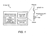
- FIG. 1 illustrates a functional block diagram of an exemplary IC chip 100, upon which is stored a fuse programming condition identifier for enabling a method of programming an electronic fuse in the field.
- IC chip 100 may be any integrated circuit chip, such as an application specific integrated circuit (ASIC) device, that includes at least one arrangement of electronic fuses (eFUSEs).
- ASIC application specific integrated circuit
- FIG. 1 shows that IC chip 100 includes a first eFUSE bank 110 and a second eFUSE bank 112, which may each be a single eFUSE or a string of eFUSEs (e.g., forming a certain logic macro within IC chip 100).
- the eFUSEs of banks 110 and/or 112 may be initially in an unprogrammed (i.e., closed) state.
- first eFUSE bank 110 and/or eFUSE bank 112 may be eFUSEs that form certain redundancy structures, such as structures commonly found in memory arrays (i.e., redundant wordlines or redundant columns).
- the eFUSEs may be programmed to disconnect a normal wordline and replace it with a redundant wordline when, for example, the normal wordline is detected as defective.
- first eFUSE bank 110 and/or second eFUSE bank 112 may be eFUSEs that form an ECID macro, which contains eFUSEs that are programmed to a value that reflects, for example, chip identification data.
- FIG. 1 shows a detail of an exemplary eFUSE 114 of first eFUSE bank 110.
- eFUSE 114 may be a poly silicon fuse link that is coupled to a voltage line (FSource) at one end, and to an NFET, which is referred to as a programming FET 116, at its opposite end.
- the gate of programming FET 116 is controlled by the chip voltage (Vdd) of IC chip 100.
- Vdd chip voltage
- a voltage is supplied by the FSource and programming FET 116 is turned on for a certain duration of time by applying Vdd, which allows controlled electromigration to occur.
- the controlled electromigration may cause a salicide/boron pile-up on an anode side of the eFUSE 114.
- the resistance across eFUSE 114 may rise (e.g., from hundreds of ohms to many Kilo-ohms), in effect opening (i.e., programming) eFUSE 114.
- IC chip 100 further includes a storage device 118, within which is stored a digital value that is related to one or more fuse programming condition identifiers 120.
- Storage device 118 may be any mechanism by which one or more bits of digital data may be stored, such as, but not limited to, a memory device or one or more eFUSEs.
- storage device 118 may be a non-volatile static random access memory (SRAM) device or a non-volatile programmable read-only memory (PROM) device.
- SRAM static random access memory
- PROM non-volatile programmable read-only memory
- storage device 118 may be one or more surplus eFUSEs within a bank of existing eFUSEs within IC chip 100, such as, but not limited to, surplus eFUSEs 114 within first eFUSE bank 110 or second eFUSE bank 112.
- storage device 118 may be, or may be part of, one or more eFUSEs of an ECID.
- One or more fuse programming condition identifiers may be represented by one or more logical values stored in a storage device, such as storage device 118.
- an integrated circuit device which is represented by IC chip 100, may include arrangements of one or more logic functions, which for simplicity are not shown in FIG. 1 .
- the conditions of an eFUSE programming process may be controlled precisely on a chip-by-chip basis during the manufacturing test operation in order to achieve a high eFUSE yield, by avoiding ruptured eFUSEs or weakly programmed eFUSEs.
- the optimal eFUSE programming conditions are variable on a chip-by-chip basis due to manufacturing process variations, e.g., from one IC chip 100 to a next IC chip 100, to a next IC chip 100, and so on.
- One exemplary method of determining the optimal eFUSE programming conditions is described in US Patent No 7,170,299 "Electronic fuse blow mimic and methods for adjusting electronic fuse blow," which is incorporated herein by reference in its entirety.
- the '299 patent describes a system, method, and program product for adjusting an environmental variable of a fuse programming of an electronic fuse.
- a mimic NFET may be coupled to a fuse programming source voltage line, a fuse programming gate voltage line, and a chip ground in the same manner as the electronic fuse, except that the mimic NFET is not attached to an electronic fuse.
- the on-current (I-ON) and off-current (I-OFF) of the mimic NFET are measured to determine a fuse programming current (1-PROGRAM) of the electronic fuse.
- the environmental variable is adjusted based on the determined programming current.
- Another example of a method is summarized with reference to a method 300 of FIG. 3 below.
- Example environmental variables include, but are not limited to, FSource, Vdd, background leakage current, I-PROGRAM, chip vs. tester ground offset, programming duration, temperature, and accuracy of test equipment.
- Fuse programming condition identifier 120 may be a digital code of one or more bits that may be correlated to a certain eFUSE programming condition, which may be a unique optimal eFUSE programming condition for a given IC chip 100.
- fuse programming condition identifier 120 may be uniquely encoded with a first value on a first IC chip 100 for correlating to a first optimal eFUSE programming condition therefor, uniquely encoded with a next unique value on a next IC chip 100 for correlating to a next optimal eFUSE programming condition therefor, and uniquely encoded with a next unique value on a next IC chip 100 for correlating to a next optimal eFUSE programming condition therefor.
- the code contained in fuse programming condition identifier 120 may correlate to one or any combination of multiple environmental variables, which include, for example, FSource, Vdd, background leakage current, I-PROGRAM, chip vs. tester ground offset, programming duration, temperature, and accuracy of test equipment.
- fuse programming condition identifier 120 is dependent on the number of or combinations of environmental variables needed to convey the optimal eFUSE programming conditions for a given IC chip.
- fuse programming condition identifier 120 may be an n-bit binary code that correlates to the actual digital value (having a certain resolution) of a certain eFUSE programming condition, e.g., an 8-bit, 10-bit, 12-bit, or 16-bit binary word that represents the actual value of, for example, FSource, Vdd, or 1-PROGRAM.
- fuse programming condition identifier 120 may be stored by the chip manufacturer during the normal manufacturing test flow.
- the bits forming fuse programming condition identifier 120 are memory bits, these bits are set to a desired state via known memory write operations.
- the bits forming fuse programming condition identifier 120 are eFUSEs 114, one or more eFUSEs 114 are set to either a programmed or unprogrammed state according to a desired code.
- the chip manufacturer may provide a fuse programming condition identifier, such as fuse programming condition identifier 120, within a chip and, thereby, provides a readable mechanism that is accessible by a customer and by which a customer may then correlate an optimal eFUSE programming condition for his/her chip.
- Correlation may occur in a variety of ways.
- a correlation may include comparison of a fuse programming condition identifier with a digitally stored value (e.g., in a lookup data table).
- a correlation may include comparison of a fuse programming condition identifier with a printed manual.
- a correlation may include reading the fuse programming condition identifier to reveal an actual programming condition.
- the fuse programming condition identifier may enable a customer to apply an optimal eFUSE programming condition, which is unique to a particular chip, in order to efficiently program eFUSEs in the field, i.e., outside of the manufacturing test environment, such as during the customer's card level test operation. More details are provided with reference to FIGS. 2 , 3 , and 4 .
- FIG. 2 illustrates a flow diagram of one embodiment of a method 200 of programming an electronic fuse by use of a fuse programming condition identifier, such as fuse programming condition identifier 120, which is stored on an integrated circuit chip, such as IC chip 100.
- Method 200 includes, but is not limited to, the following steps.
- a fuse programming condition identifier that is stored in one or more memory bits on a chip are accessed.
- fuse programming condition identifier 120 of storage device 118 is accessed by the chip purchaser.
- the bits forming fuse programming condition identifier 120 are memory bits, these bits are accessed via known memory read operations.
- the bits forming fuse programming condition identifier 120 are eFUSEs 114
- the programmed or unprogrammed state of the one or more eFUSEs 114 is detected via standard circuitry that is associated with, for example, first eFUSE bank 110 or second eFUSE bank 112.
- one or more optimal eFUSE programming conditions are correlated with the information of fuse programming condition identifier, such as correlated with the information of fuse programming condition identifier 120 of storage device 118 of IC chip 100.
- this correlation may be performed by the chip manufacturer providing the chip purchaser any standard method of correlating each possible value that may be encoded in fuse programming condition identifier 120 with an optimal eFUSE programming condition e.g., a software lookup table, an electronic or printed guidebook, or a telephone customer service center.
- one or more fuses on the IC chip are programmed utilizing the one or more correlated eFUSE programming conditions.
- the IC chip purchaser applies the correlated optimal eFUSE programming conditions that were extracted from his/her IC chip during, for example, manufacturing wafer and/or module test operations, in order to program one or more IC chip purchaser-selected eFUSEs 114.
- FIG. 3 illustrates a flow diagram of one embodiment of a method 300 of determining one or more optimal fuse programming condition identifiers for enabling a method of programming an electronic fuse, such as programming an electronic fuse by use of method 300.
- one or more optimal fuse programming condition identifiers may be determined by use of method 300 on a chip-by-chip basis during a manufacturing test operation.
- Method 300 includes, but is not limited to, the following steps.
- a plurality of IC test chips are tested for the optimal chip programming conditions.
- a chip manufacturer executes an eFUSE programming process on a plurality (e.g., hundreds to millions) of IC test chips, in order to understand the preferred way to program the eFUSEs for a selection of environmental variations.
- a plurality of test values of a correlating parameter are determined from the plurality of IC test chips.
- a correlating parameter may be any measurable value that may indicate a corresponding value for a fuse programming environmental condition. For example, a fuse programming current may be measured at a particular fuse programming condition value, e.g., a particular Vdd value.
- Each of the plurality of test values may be for one of a plurality of fuse programming condition sets.
- the test values are based upon the eFUSE-programming information that is gathered in step 310 for every known process variation. For example, physical measurements of an IC test chip may be mapped to certain eFUSE-programming parameters.
- each IC test chip is tested for an actual value of the correlating parameter.
- the background leakage current (I-BKG) of the IC chip under test is measured, the on-current (I-ON) of a mimic programming FET at nominal Vdd and FSource values is measured, I-BKG is subtracted from I-ON in order to determine the fuse programming current (I-PROGRAM).
- an optimal one of the plurality of fuse programming condition sets is determined for the IC chip under test by comparing an actual value to a plurality of test values.
- a three-way decision may be performed. Specifically, an upper level threshold, for example, 14mA, and a lower level threshold, for example, 10mA, are set for the determined I-PROGRAM. If the determined I-PROGRAM is higher than the upper level threshold, here 14mA, the programming Vdd may be decreased, for example, from the preset 1.35V to 1.20V.
- the programming Vdd may be increased, for example, from the preset 1.35V to 1.50V. Also, if the determined I-PROGRAM is within the range between the upper level threshold, here 14mA, and the lower level threshold, here 10mA, the programming Vdd may be considered proper and be maintained the same as the preset value, here 1.35V. In doing so, an optimal value of the programming Vdd is determined that correlates to the actual I-PROGRAM of the IC chip under test.
- an indicator of the optimal one of the plurality of fuse programming condition sets is stored as the fuse programming condition identifier. For example, if the optimal programming Vdd is 1.20V, a 2-bit fuse programming condition identifier 120 for the IC chip under test may be set to "00;” if the optimal programming Vdd is 1.35V, the 2-bit fuse programming condition identifier 120 may be set to "01;” and if the optimal programming Vdd is 1.50V, the 2-bit fuse programming condition identifier 120 may be set to "10.”
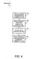
- FIG. 4 illustrates a flow diagram of a method 400 of programming an electronic fuse in the field by, for example, an integrated circuit chip customer.
- Method 400 includes, but is not limited to, the following steps.
- one or more optimal fuse programming conditions are determined. These conditions will apply to all eFUSEs on a given chip such as IC chip 100 by, for example, performing steps 310 through 316 of method 300 of FIG. 3 .
- an indicator of the one or more optimal fuse programming conditions is stored in one or more memory bits on the IC chip under test.
- an indicator of the one or more optimal fuse programming conditions is stored in fuse programming condition identifier 120 of storage device 118 of IC chip 100, as described, for example, in FIG. 1 and in step 318 of method 300 of FIG. 3 .
- the chip manufacturer provides an IC chip, such as IC chip 100, to a customer in the field.
- the IC chip customer is instructed on how to access the one or more optimal fuse programming conditions from the one or more memory bits in order to enable the customer to program at least one of the one or more eFUSEs.
- the IC chip manufacturer may provide instructions to the IC chip customer on how to access, for example, fuse programming condition identifier 120 of storage device 118 of IC chip 100.
- the IC chip manufacturer may provide the chip purchaser a standard method of correlating each possible value that may be encoded in fuse programming condition identifier 120 with a respective optimal eFUSE programming condition. Standard correlation methods include, but are not limited to, a software lookup table, an electronic or printed guidebook, or calling by telephone a customer service center.
- FIG. 5 shows a block diagram of an example design flow 500.
- Design flow 500 may vary depending on the type of IC being designed.
- a design flow 500 for building an application specific IC (ASIC) may differ from a design flow 500 for designing a standard component.
- Design structure 520 is preferably an input to a design process 510 and may come from an IP provider, a core developer, or other design company or may be generated by the operator of the design flow, or from other sources.
- Design structure 520 comprises IC chip 100 in the form of schematics or HDL, a hardware-description language (e.g., Verilog, VHDL, C, etc.). Design structure 520 may be contained on one or more machine readable medium.
- design structure 520 may be a text file or a graphical representation of IC chip 100.
- Design process 510 preferably synthesizes (or translates) IC chip 100 into a netlist 580, where netlist 580 is, for example, a list of wires, transistors, logic gates, control circuits, I/O, models, etc. that describes the connections to other elements and circuits in an integrated circuit design and recorded on at least one of machine readable medium. This may be an iterative process in which netlist 580 is resynthesized one or more times depending on design specifications and parameters for the circuit.
- Design process 510 may include using a variety of inputs; for example, inputs from library elements 530 which may house a set of commonly used elements, circuits, and devices, including models, layouts, and symbolic representations, for a given manufacturing technology (e.g., different technology nodes, 32nm, 45 nm, 90 nm, etc.), design specifications 540, characterization data 550, verification data 560, design rules 570, and test data files 585 (which may include test patterns and other testing information). Design process 510 may further include, for example, standard circuit design processes such as timing analysis, verification, design rule checking, place and route operations, etc.
- One of ordinary skill in the art of integrated circuit design can appreciate the extent of possible electronic design automation tools and applications used in design process 510 without deviating from the scope and spirit of the invention.
- the design structure of the invention is not limited to any specific design flow.
- design process 510 preferably translates IC chip 100, along with the rest of the integrated circuit design (if applicable), into a final design structure 590 (e.g., information stored in a GDS storage medium).
- Final design structure 590 may comprise information such as, for example, test data files, design content files, manufacturing data, layout parameters, wires, levels of metal, vias, shapes, test data, data for routing through the manufacturing line, and any other data required by a semiconductor manufacturer to produce IC chip 100.
- Final design structure 590 may then proceed to a stage 595 where, for example, final design structure 590: proceeds to tape-out, is released to manufacturing, is sent to another design house or is sent back to the customer.
Landscapes
- Semiconductor Integrated Circuits (AREA)
- Design And Manufacture Of Integrated Circuits (AREA)
- Powder Metallurgy (AREA)
Claims (15)
- Procédé (300) de programmation d'un fusible électronique d'une puce (100) sur le terrain par un client du fabricant de la puce, le procédé étant caractérisé par le fait de comprendre les étapes consistant à :déterminer (316, 410) une ou plusieurs conditions de programmation de fusibles optimales pour un ou plusieurs fusibles électroniques d'une puce,mémoriser (318, 412) un indicateur desdites une ou plusieurs conditions de programmation de fusibles optimales dans un ou plusieurs bits de mémoire sur ladite puce,fournir (414) ladite puce à un client sur le terrain, etdonner pour instruction (416) audit client d'accéder auxdites une ou plusieurs conditions de programmation de fusibles optimales à partir desdits un ou plusieurs bits de mémoire pour permettre audit client de programmer au moins l'un desdits un ou plusieurs fusibles électroniques.
- Procédé selon la revendication 1, dans lequel lesdits un ou plusieurs bits de mémoire sont inclus dans une macro d'identification de puce électronique.
- Procédé selon la revendication 1 ou 2, dans lequel lesdits un ou plusieurs bits de mémoire comprennent un fusible électronique.
- Procédé selon l'une quelconque des revendications précédentes, dans lequel lesdites une ou plusieurs conditions de programmation de fusibles optimales sont déterminées sur une base puce par puce au cours d'un essai de fabrication de ladite puce.
- Procédé selon la revendication 4, dans lequel ladite détermination desdites une ou plusieurs conditions de programmation de fusibles optimales comprend les étapes consistant à :tester une pluralité de puces d'essai en ce qui concerne une ou plusieurs conditions de programmation de fusibles optimales,déterminer une pluralité de valeurs d'essai d'un paramètre de corrélation à partir de ladite pluralité de puces d'essai, chaque valeur de ladite pluralité de valeurs d'essai correspondant à un ensemble d'une pluralité d'ensembles de conditions de programmation de fusibles,tester ladite puce en ce qui concerne une valeur actuelle dudit paramètre de corrélation,déterminer un ensemble optimal de ladite pluralité d'ensembles de conditions de programmation de fusibles pour ladite puce en comparant ladite valeur actuelle à ladite pluralité de valeurs d'essai,mémoriser un indicateur dudit ensemble optimal de ladite pluralité d'ensembles de conditions de programmation de fusibles comme ledit identificateur de conditions de programmation de fusibles.
- Procédé selon la revendication 5, dans lequel ledit paramètre de corrélation est un courant de programmation de fusible pour ladite puce.
- Procédé selon la revendication 6, dans lequel ledit courant de programmation de fusible est déterminé en :mesurant un courant de fond sur une ligne de source de programmation de fusible d'un fusible électronique de ladite puce,mesurant un courant « actif » sur ladite ligne de source de programmation de fusible à une valeur prédéterminée d'un paramètre de programmation de puce sans exposer ledit fusible électronique audit courant « actif », etdéterminant une différence entre ledit courant « actif » et ledit courant de fond.
- Procédé selon l'une quelconque des revendications précédentes, dans lequel lesdites une ou plusieurs conditions de programmation de fusibles optimales comprennent une condition sélectionnée à partir du groupe constitué d'une tension de source de programmation de fusible, d'une tension de grille de programmation de fusible, d'un temps de programmation de fusible, et toute combinaison de ceux-ci.
- Structure de conception destinée à programmer un fusible électronique d'une puce, la structure de conception étant caractérisée par le fait de comprendre :un moyen destiné à déterminer (316, 410) une ou plusieurs conditions de programmation de fusibles optimales pour un ou plusieurs fusibles électroniques d'une puce,un moyen destiné à mémoriser (318, 412) un indicateur desdites une ou plusieurs conditions de programmation de fusibles optimales dans un ou plusieurs bits de mémoire sur ladite puce,un moyen destiné à fournir (414) ladite puce à un client sur le terrain, etun moyen destiné à donner pour instruction (416) audit client d'accéder auxdites une ou plusieurs conditions de programmation de fusibles optimales à partir desdits un ou plusieurs bits de mémoire pour permettre audit client de programmer au moins l'un desdits un ou plusieurs fusibles électroniques.
- Structure de conception selon la revendication 9, dans laquelle lesdits un ou plusieurs bits de mémoire sont inclus dans une macro d'identification de puce électronique.
- Structure de conception selon la revendication 9 ou 10, dans laquelle lesdits un ou plusieurs bits de mémoire comprennent un fusible électronique.
- Structure de conception selon la revendication 9, 10 ou 11, dans laquelle ledit moyen de détermination desdites une ou plusieurs conditions de programmation de fusibles optimales est commandé sur une base puce par puce au cours d'un essai de fabrication de ladite puce.
- Structure de conception selon l'une quelconque des revendications 9 à 12, dans laquelle ledit moyen de détermination desdites une ou plusieurs conditions de programmation de fusibles optimales comprend :un moyen destiné à tester une pluralité de puces d'essai en ce qui concerne une ou plusieurs conditions de programmation de fusibles optimales,un moyen destiné à déterminer une pluralité de valeurs d'essai d'un paramètre de corrélation à partir de ladite pluralité de puces d'essai, chaque valeur de ladite pluralité de valeurs d'essai correspondant à un ensemble d'une pluralité d'ensembles de conditions de programmation de fusibles,un moyen destiné à tester ladite puce en ce qui concerne une valeur actuelle dudit paramètre de corrélation,un moyen destiné à déterminer un ensemble optimal de ladite pluralité d'ensembles de conditions de programmation de fusibles pour ladite puce en comparant ladite valeur actuelle à ladite pluralité de valeurs d'essai, etun moyen destiné à mémoriser un indicateur dudit ensemble optimal de ladite pluralité d'ensembles de conditions de programmation de fusibles comme ledit identificateur de conditions de programmation de fusibles.
- Structure de conception selon la revendication 13, dans laquelle ledit paramètre de corrélation est un courant de programmation de fusible pour ladite puce.
- Structure de conception selon la revendication 14, dans laquelle ledit courant de programmation de fusible est déterminé en :mesurant un courant de fond sur une ligne de source de programmation de fusible d'un fusible électronique de ladite puce,mesurant un courant « actif » sur ladite ligne de source de programmation de fusible à une valeur prédéterminée d'un paramètre de programmation de puce sans exposer ledit fusible électronique audit courant « actif », etdéterminant une différence entre ledit courant « actif » et ledit courant de fond.
Applications Claiming Priority (3)
| Application Number | Priority Date | Filing Date | Title |
|---|---|---|---|
| US11/555,323 US7518899B2 (en) | 2006-11-01 | 2006-11-01 | Method of providing optimal field programming of electronic fuses |
| US11/850,477 US7791972B2 (en) | 2006-11-01 | 2007-09-05 | Design structure for providing optimal field programming of electronic fuses |
| PCT/EP2007/061109 WO2008052885A1 (fr) | 2006-11-01 | 2007-10-17 | Procédé de fourniture d'une programmation par champ optimale de fusibles électroniques |
Publications (2)
| Publication Number | Publication Date |
|---|---|
| EP2078304A1 EP2078304A1 (fr) | 2009-07-15 |
| EP2078304B1 true EP2078304B1 (fr) | 2011-03-23 |
Family
ID=38969791
Family Applications (1)
| Application Number | Title | Priority Date | Filing Date |
|---|---|---|---|
| EP07821474A Not-in-force EP2078304B1 (fr) | 2006-11-01 | 2007-10-17 | Procédé de fourniture d'une programmation par champ optimale de fusibles électroniques |
Country Status (7)
| Country | Link |
|---|---|
| US (1) | US7791972B2 (fr) |
| EP (1) | EP2078304B1 (fr) |
| JP (1) | JP4659119B2 (fr) |
| KR (1) | KR101055917B1 (fr) |
| AT (1) | ATE503251T1 (fr) |
| DE (1) | DE602007013438D1 (fr) |
| WO (1) | WO2008052885A1 (fr) |
Families Citing this family (11)
| Publication number | Priority date | Publication date | Assignee | Title |
|---|---|---|---|---|
| US8028924B2 (en) * | 2009-09-15 | 2011-10-04 | International Business Machines Corporation | Device and method for providing an integrated circuit with a unique identification |
| US8719648B2 (en) | 2011-07-27 | 2014-05-06 | International Business Machines Corporation | Interleaving of memory repair data compression and fuse programming operations in single fusebay architecture |
| US8537627B2 (en) | 2011-09-01 | 2013-09-17 | International Business Machines Corporation | Determining fusebay storage element usage |
| US10598703B2 (en) | 2015-07-20 | 2020-03-24 | Eaton Intelligent Power Limited | Electric fuse current sensing systems and monitoring methods |
| JP6207670B1 (ja) * | 2016-05-24 | 2017-10-04 | 三菱電機株式会社 | ワンタイムメモリの制御装置 |
| US10223531B2 (en) | 2016-12-30 | 2019-03-05 | Google Llc | Secure device state apparatus and method and lifecycle management |
| US10523048B2 (en) * | 2018-02-16 | 2019-12-31 | Monolithic Power Systems, Inc. | Power supply and power supplying method with power backup and power sharing |
| US10892637B2 (en) * | 2018-02-16 | 2021-01-12 | Monolithic Power Systems, Inc. | Power supply and power supplying method with power backup |
| US10855174B2 (en) * | 2018-02-16 | 2020-12-01 | Monolithic Power Systems, Inc. | Power supply and power supply method with power sharing and overshoot preventing |
| US11143718B2 (en) | 2018-05-31 | 2021-10-12 | Eaton Intelligent Power Limited | Monitoring systems and methods for estimating thermal-mechanical fatigue in an electrical fuse |
| US11289298B2 (en) | 2018-05-31 | 2022-03-29 | Eaton Intelligent Power Limited | Monitoring systems and methods for estimating thermal-mechanical fatigue in an electrical fuse |
Family Cites Families (10)
| Publication number | Priority date | Publication date | Assignee | Title |
|---|---|---|---|---|
| US4268911A (en) * | 1979-06-21 | 1981-05-19 | Fairchild Camera And Instrument Corp. | ROM Program security circuits |
| JPS5736497A (en) * | 1980-08-14 | 1982-02-27 | Toshiba Corp | Semiconductor integrated circuit |
| JPS5936497A (ja) | 1982-08-23 | 1984-02-28 | Mitsuyoshi Sangyo Kk | 音響機器の前面に装着するプラスチツクグリル枠に金属グリルを取付ける方法 |
| US6034882A (en) * | 1998-11-16 | 2000-03-07 | Matrix Semiconductor, Inc. | Vertically stacked field programmable nonvolatile memory and method of fabrication |
| US6483736B2 (en) * | 1998-11-16 | 2002-11-19 | Matrix Semiconductor, Inc. | Vertically stacked field programmable nonvolatile memory and method of fabrication |
| US6437653B1 (en) | 2000-09-28 | 2002-08-20 | Sun Microsystems, Inc. | Method and apparatus for providing a variable inductor on a semiconductor chip |
| US6876594B2 (en) * | 2002-12-26 | 2005-04-05 | Texas Instruments Incorporated | Integrated circuit with programmable fuse array |
| GB0419465D0 (en) * | 2004-09-02 | 2004-10-06 | Cavendish Kinetics Ltd | Method and apparatus for programming and reading codes |
| US20060136858A1 (en) * | 2004-12-17 | 2006-06-22 | International Business Machines Corporation | Utilizing fuses to store control parameters for external system components |
| JP2008097696A (ja) * | 2006-10-11 | 2008-04-24 | Elpida Memory Inc | 半導体装置 |
-
2007
- 2007-09-05 US US11/850,477 patent/US7791972B2/en not_active Expired - Fee Related
- 2007-10-17 KR KR1020097006381A patent/KR101055917B1/ko not_active IP Right Cessation
- 2007-10-17 EP EP07821474A patent/EP2078304B1/fr not_active Not-in-force
- 2007-10-17 DE DE602007013438T patent/DE602007013438D1/de active Active
- 2007-10-17 JP JP2009533792A patent/JP4659119B2/ja not_active Expired - Fee Related
- 2007-10-17 WO PCT/EP2007/061109 patent/WO2008052885A1/fr active Application Filing
- 2007-10-17 AT AT07821474T patent/ATE503251T1/de not_active IP Right Cessation
Also Published As
| Publication number | Publication date |
|---|---|
| JP2010508654A (ja) | 2010-03-18 |
| ATE503251T1 (de) | 2011-04-15 |
| DE602007013438D1 (de) | 2011-05-05 |
| JP4659119B2 (ja) | 2011-03-30 |
| US7791972B2 (en) | 2010-09-07 |
| US20080104551A1 (en) | 2008-05-01 |
| KR101055917B1 (ko) | 2011-08-09 |
| KR20090068322A (ko) | 2009-06-26 |
| EP2078304A1 (fr) | 2009-07-15 |
| WO2008052885A1 (fr) | 2008-05-08 |
Similar Documents
| Publication | Publication Date | Title |
|---|---|---|
| EP2078304B1 (fr) | Procédé de fourniture d'une programmation par champ optimale de fusibles électroniques | |
| US7518899B2 (en) | Method of providing optimal field programming of electronic fuses | |
| US7609577B2 (en) | Design structure for improving sensing margin of electrically programmable fuses | |
| US20040261049A1 (en) | Circuit and method for error test, recordation, and repair | |
| US7764531B2 (en) | Implementing precise resistance measurement for 2D array efuse bit cell using differential sense amplifier, balanced bitlines, and programmable reference resistor | |
| US7725844B2 (en) | Method and circuit for implementing eFuse sense amplifier verification | |
| US7733096B2 (en) | Methods of testing fuse elements for memory devices | |
| US9053889B2 (en) | Electronic fuse cell and array | |
| US6983404B2 (en) | Method and apparatus for checking the resistance of programmable elements | |
| US7161857B2 (en) | Memory redundancy programming | |
| US8159894B2 (en) | One time programmable memory | |
| US7915949B2 (en) | Implementing eFuse resistance determination before initiating eFuse blow | |
| US8193851B2 (en) | Fuse circuit of semiconductor device and method for monitoring fuse state thereof | |
| US7289358B2 (en) | MTP NVM elements by-passed for programming | |
| US7689950B2 (en) | Implementing Efuse sense amplifier testing without blowing the Efuse | |
| US9805815B1 (en) | Electrical fuse bit cell and mask set | |
| US20090212850A1 (en) | Method and Circuit for Implementing Efuse Resistance Screening | |
| EP1154438A2 (fr) | Circuit programmable avec fonction de prévisualisation | |
| US6704676B2 (en) | Method and circuit configuration for identifying an operating property of an integrated circuit | |
| US20080232152A1 (en) | Method and Structure for Implementing a Reprogrammable ROM | |
| KR20110073905A (ko) | 반도체 장치 | |
| TWI547951B (zh) | 記憶胞及記憶體裝置 | |
| Pavlov et al. | Traditional SRAM Fault Models and Test Practices | |
| To et al. | Latent Flash Single Bit and Multiple Bits Systematic Approach to Failure Analysis |
Legal Events
| Date | Code | Title | Description |
|---|---|---|---|
| PUAI | Public reference made under article 153(3) epc to a published international application that has entered the european phase |
Free format text: ORIGINAL CODE: 0009012 |
|
| 17P | Request for examination filed |
Effective date: 20090508 |
|
| AK | Designated contracting states |
Kind code of ref document: A1 Designated state(s): AT BE BG CH CY CZ DE DK EE ES FI FR GB GR HU IE IS IT LI LT LU LV MC MT NL PL PT RO SE SI SK TR |
|
| 17Q | First examination report despatched |
Effective date: 20090922 |
|
| GRAP | Despatch of communication of intention to grant a patent |
Free format text: ORIGINAL CODE: EPIDOSNIGR1 |
|
| DAX | Request for extension of the european patent (deleted) | ||
| GRAS | Grant fee paid |
Free format text: ORIGINAL CODE: EPIDOSNIGR3 |
|
| GRAA | (expected) grant |
Free format text: ORIGINAL CODE: 0009210 |
|
| AK | Designated contracting states |
Kind code of ref document: B1 Designated state(s): AT BE BG CH CY CZ DE DK EE ES FI FR GB GR HU IE IS IT LI LT LU LV MC MT NL PL PT RO SE SI SK TR |
|
| REG | Reference to a national code |
Ref country code: GB Ref legal event code: FG4D |
|
| REG | Reference to a national code |
Ref country code: CH Ref legal event code: EP |
|
| REG | Reference to a national code |
Ref country code: IE Ref legal event code: FG4D |
|
| REG | Reference to a national code |
Ref country code: DE Ref legal event code: R084 Ref document number: 602007013438 Country of ref document: DE |
|
| REG | Reference to a national code |
Ref country code: GB Ref legal event code: 746 Effective date: 20110412 |
|
| REF | Corresponds to: |
Ref document number: 602007013438 Country of ref document: DE Date of ref document: 20110505 Kind code of ref document: P |
|
| REG | Reference to a national code |
Ref country code: DE Ref legal event code: R096 Ref document number: 602007013438 Country of ref document: DE Effective date: 20110505 |
|
| REG | Reference to a national code |
Ref country code: NL Ref legal event code: VDEP Effective date: 20110323 |
|
| PG25 | Lapsed in a contracting state [announced via postgrant information from national office to epo] |
Ref country code: SE Free format text: LAPSE BECAUSE OF FAILURE TO SUBMIT A TRANSLATION OF THE DESCRIPTION OR TO PAY THE FEE WITHIN THE PRESCRIBED TIME-LIMIT Effective date: 20110323 Ref country code: GR Free format text: LAPSE BECAUSE OF FAILURE TO SUBMIT A TRANSLATION OF THE DESCRIPTION OR TO PAY THE FEE WITHIN THE PRESCRIBED TIME-LIMIT Effective date: 20110624 Ref country code: LV Free format text: LAPSE BECAUSE OF FAILURE TO SUBMIT A TRANSLATION OF THE DESCRIPTION OR TO PAY THE FEE WITHIN THE PRESCRIBED TIME-LIMIT Effective date: 20110323 Ref country code: LT Free format text: LAPSE BECAUSE OF FAILURE TO SUBMIT A TRANSLATION OF THE DESCRIPTION OR TO PAY THE FEE WITHIN THE PRESCRIBED TIME-LIMIT Effective date: 20110323 |
|
| LTIE | Lt: invalidation of european patent or patent extension |
Effective date: 20110323 |
|
| PG25 | Lapsed in a contracting state [announced via postgrant information from national office to epo] |
Ref country code: AT Free format text: LAPSE BECAUSE OF FAILURE TO SUBMIT A TRANSLATION OF THE DESCRIPTION OR TO PAY THE FEE WITHIN THE PRESCRIBED TIME-LIMIT Effective date: 20110323 Ref country code: SI Free format text: LAPSE BECAUSE OF FAILURE TO SUBMIT A TRANSLATION OF THE DESCRIPTION OR TO PAY THE FEE WITHIN THE PRESCRIBED TIME-LIMIT Effective date: 20110323 Ref country code: CY Free format text: LAPSE BECAUSE OF FAILURE TO SUBMIT A TRANSLATION OF THE DESCRIPTION OR TO PAY THE FEE WITHIN THE PRESCRIBED TIME-LIMIT Effective date: 20110323 Ref country code: BG Free format text: LAPSE BECAUSE OF FAILURE TO SUBMIT A TRANSLATION OF THE DESCRIPTION OR TO PAY THE FEE WITHIN THE PRESCRIBED TIME-LIMIT Effective date: 20110623 Ref country code: FI Free format text: LAPSE BECAUSE OF FAILURE TO SUBMIT A TRANSLATION OF THE DESCRIPTION OR TO PAY THE FEE WITHIN THE PRESCRIBED TIME-LIMIT Effective date: 20110323 |
|
| PG25 | Lapsed in a contracting state [announced via postgrant information from national office to epo] |
Ref country code: BE Free format text: LAPSE BECAUSE OF FAILURE TO SUBMIT A TRANSLATION OF THE DESCRIPTION OR TO PAY THE FEE WITHIN THE PRESCRIBED TIME-LIMIT Effective date: 20110323 |
|
| PG25 | Lapsed in a contracting state [announced via postgrant information from national office to epo] |
Ref country code: PT Free format text: LAPSE BECAUSE OF FAILURE TO SUBMIT A TRANSLATION OF THE DESCRIPTION OR TO PAY THE FEE WITHIN THE PRESCRIBED TIME-LIMIT Effective date: 20110725 Ref country code: EE Free format text: LAPSE BECAUSE OF FAILURE TO SUBMIT A TRANSLATION OF THE DESCRIPTION OR TO PAY THE FEE WITHIN THE PRESCRIBED TIME-LIMIT Effective date: 20110323 |
|
| PG25 | Lapsed in a contracting state [announced via postgrant information from national office to epo] |
Ref country code: IS Free format text: LAPSE BECAUSE OF FAILURE TO SUBMIT A TRANSLATION OF THE DESCRIPTION OR TO PAY THE FEE WITHIN THE PRESCRIBED TIME-LIMIT Effective date: 20110723 Ref country code: ES Free format text: LAPSE BECAUSE OF FAILURE TO SUBMIT A TRANSLATION OF THE DESCRIPTION OR TO PAY THE FEE WITHIN THE PRESCRIBED TIME-LIMIT Effective date: 20110704 Ref country code: SK Free format text: LAPSE BECAUSE OF FAILURE TO SUBMIT A TRANSLATION OF THE DESCRIPTION OR TO PAY THE FEE WITHIN THE PRESCRIBED TIME-LIMIT Effective date: 20110323 Ref country code: CZ Free format text: LAPSE BECAUSE OF FAILURE TO SUBMIT A TRANSLATION OF THE DESCRIPTION OR TO PAY THE FEE WITHIN THE PRESCRIBED TIME-LIMIT Effective date: 20110323 Ref country code: RO Free format text: LAPSE BECAUSE OF FAILURE TO SUBMIT A TRANSLATION OF THE DESCRIPTION OR TO PAY THE FEE WITHIN THE PRESCRIBED TIME-LIMIT Effective date: 20110323 |
|
| PG25 | Lapsed in a contracting state [announced via postgrant information from national office to epo] |
Ref country code: NL Free format text: LAPSE BECAUSE OF FAILURE TO SUBMIT A TRANSLATION OF THE DESCRIPTION OR TO PAY THE FEE WITHIN THE PRESCRIBED TIME-LIMIT Effective date: 20110323 |
|
| PLBE | No opposition filed within time limit |
Free format text: ORIGINAL CODE: 0009261 |
|
| STAA | Information on the status of an ep patent application or granted ep patent |
Free format text: STATUS: NO OPPOSITION FILED WITHIN TIME LIMIT |
|
| 26N | No opposition filed |
Effective date: 20111227 |
|
| PG25 | Lapsed in a contracting state [announced via postgrant information from national office to epo] |
Ref country code: DK Free format text: LAPSE BECAUSE OF FAILURE TO SUBMIT A TRANSLATION OF THE DESCRIPTION OR TO PAY THE FEE WITHIN THE PRESCRIBED TIME-LIMIT Effective date: 20110323 Ref country code: PL Free format text: LAPSE BECAUSE OF FAILURE TO SUBMIT A TRANSLATION OF THE DESCRIPTION OR TO PAY THE FEE WITHIN THE PRESCRIBED TIME-LIMIT Effective date: 20110323 |
|
| REG | Reference to a national code |
Ref country code: DE Ref legal event code: R097 Ref document number: 602007013438 Country of ref document: DE Effective date: 20111227 |
|
| PG25 | Lapsed in a contracting state [announced via postgrant information from national office to epo] |
Ref country code: MC Free format text: LAPSE BECAUSE OF NON-PAYMENT OF DUE FEES Effective date: 20111031 Ref country code: IT Free format text: LAPSE BECAUSE OF FAILURE TO SUBMIT A TRANSLATION OF THE DESCRIPTION OR TO PAY THE FEE WITHIN THE PRESCRIBED TIME-LIMIT Effective date: 20110323 |
|
| REG | Reference to a national code |
Ref country code: CH Ref legal event code: PL |
|
| PG25 | Lapsed in a contracting state [announced via postgrant information from national office to epo] |
Ref country code: LI Free format text: LAPSE BECAUSE OF NON-PAYMENT OF DUE FEES Effective date: 20111031 Ref country code: CH Free format text: LAPSE BECAUSE OF NON-PAYMENT OF DUE FEES Effective date: 20111031 |
|
| REG | Reference to a national code |
Ref country code: IE Ref legal event code: MM4A |
|
| PG25 | Lapsed in a contracting state [announced via postgrant information from national office to epo] |
Ref country code: IE Free format text: LAPSE BECAUSE OF NON-PAYMENT OF DUE FEES Effective date: 20111017 |
|
| PG25 | Lapsed in a contracting state [announced via postgrant information from national office to epo] |
Ref country code: MT Free format text: LAPSE BECAUSE OF FAILURE TO SUBMIT A TRANSLATION OF THE DESCRIPTION OR TO PAY THE FEE WITHIN THE PRESCRIBED TIME-LIMIT Effective date: 20110323 |
|
| PG25 | Lapsed in a contracting state [announced via postgrant information from national office to epo] |
Ref country code: LU Free format text: LAPSE BECAUSE OF NON-PAYMENT OF DUE FEES Effective date: 20111017 |
|
| PG25 | Lapsed in a contracting state [announced via postgrant information from national office to epo] |
Ref country code: TR Free format text: LAPSE BECAUSE OF FAILURE TO SUBMIT A TRANSLATION OF THE DESCRIPTION OR TO PAY THE FEE WITHIN THE PRESCRIBED TIME-LIMIT Effective date: 20110323 |
|
| PG25 | Lapsed in a contracting state [announced via postgrant information from national office to epo] |
Ref country code: HU Free format text: LAPSE BECAUSE OF FAILURE TO SUBMIT A TRANSLATION OF THE DESCRIPTION OR TO PAY THE FEE WITHIN THE PRESCRIBED TIME-LIMIT Effective date: 20110323 |
|
| REG | Reference to a national code |
Ref country code: FR Ref legal event code: PLFP Year of fee payment: 9 |
|
| PGFP | Annual fee paid to national office [announced via postgrant information from national office to epo] |
Ref country code: GB Payment date: 20151014 Year of fee payment: 9 |
|
| PGFP | Annual fee paid to national office [announced via postgrant information from national office to epo] |
Ref country code: FR Payment date: 20151008 Year of fee payment: 9 |
|
| REG | Reference to a national code |
Ref country code: DE Ref legal event code: R082 Ref document number: 602007013438 Country of ref document: DE Representative=s name: RICHARDT PATENTANWAELTE PARTG MBB, DE Ref country code: DE Ref legal event code: R081 Ref document number: 602007013438 Country of ref document: DE Owner name: GLOBALFOUNDRIES INC., KY Free format text: FORMER OWNER: INTERNATIONAL BUSINESS MACHINES CORPORATION, ARMONK, N.Y., US |
|
| REG | Reference to a national code |
Ref country code: DE Ref legal event code: R081 Ref document number: 602007013438 Country of ref document: DE Owner name: GLOBALFOUNDRIES INC., KY Free format text: FORMER OWNER: GLOBALFOUNDRIES US 2 LLC (N.D.GES.DES STAATES DELAWARE), HOPEWELL JUNCTION, N.Y., US Ref country code: DE Ref legal event code: R082 Ref document number: 602007013438 Country of ref document: DE Representative=s name: RICHARDT PATENTANWAELTE PARTG MBB, DE |
|
| REG | Reference to a national code |
Ref country code: FR Ref legal event code: TP Owner name: GLOBALFOUNDRIES INC., GB Effective date: 20160829 |
|
| GBPC | Gb: european patent ceased through non-payment of renewal fee |
Effective date: 20161017 |
|
| REG | Reference to a national code |
Ref country code: FR Ref legal event code: ST Effective date: 20170630 |
|
| PG25 | Lapsed in a contracting state [announced via postgrant information from national office to epo] |
Ref country code: FR Free format text: LAPSE BECAUSE OF NON-PAYMENT OF DUE FEES Effective date: 20161102 Ref country code: GB Free format text: LAPSE BECAUSE OF NON-PAYMENT OF DUE FEES Effective date: 20161017 |
|
| PGFP | Annual fee paid to national office [announced via postgrant information from national office to epo] |
Ref country code: DE Payment date: 20171011 Year of fee payment: 11 |
|
| REG | Reference to a national code |
Ref country code: DE Ref legal event code: R119 Ref document number: 602007013438 Country of ref document: DE |
|
| PG25 | Lapsed in a contracting state [announced via postgrant information from national office to epo] |
Ref country code: DE Free format text: LAPSE BECAUSE OF NON-PAYMENT OF DUE FEES Effective date: 20190501 |