EP2078128B1 - Mounting device for a line replaceable unit in an aircraft and a method for using the same - Google Patents
Mounting device for a line replaceable unit in an aircraft and a method for using the same Download PDFInfo
- Publication number
- EP2078128B1 EP2078128B1 EP20070872191 EP07872191A EP2078128B1 EP 2078128 B1 EP2078128 B1 EP 2078128B1 EP 20070872191 EP20070872191 EP 20070872191 EP 07872191 A EP07872191 A EP 07872191A EP 2078128 B1 EP2078128 B1 EP 2078128B1
- Authority
- EP
- European Patent Office
- Prior art keywords
- clamping element
- shaft portion
- visual position
- fixing block
- opening
- Prior art date
- Legal status (The legal status is an assumption and is not a legal conclusion. Google has not performed a legal analysis and makes no representation as to the accuracy of the status listed.)
- Not-in-force
Links
- 238000000034 method Methods 0.000 title claims abstract description 11
- 230000000007 visual effect Effects 0.000 claims abstract description 32
- 230000000712 assembly Effects 0.000 claims 3
- 238000000429 assembly Methods 0.000 claims 3
- 238000009434 installation Methods 0.000 abstract description 3
- 239000000463 material Substances 0.000 description 1
- 239000002184 metal Substances 0.000 description 1
- 238000012986 modification Methods 0.000 description 1
- 230000004048 modification Effects 0.000 description 1
- 229910001220 stainless steel Inorganic materials 0.000 description 1
- 239000010935 stainless steel Substances 0.000 description 1
Images


Classifications
-
- H—ELECTRICITY
- H05—ELECTRIC TECHNIQUES NOT OTHERWISE PROVIDED FOR
- H05K—PRINTED CIRCUITS; CASINGS OR CONSTRUCTIONAL DETAILS OF ELECTRIC APPARATUS; MANUFACTURE OF ASSEMBLAGES OF ELECTRICAL COMPONENTS
- H05K7/00—Constructional details common to different types of electric apparatus
- H05K7/14—Mounting supporting structure in casing or on frame or rack
- H05K7/1401—Mounting supporting structure in casing or on frame or rack comprising clamping or extracting means
- H05K7/1411—Mounting supporting structure in casing or on frame or rack comprising clamping or extracting means for securing or extracting box-type drawers
- H05K7/1412—Mounting supporting structure in casing or on frame or rack comprising clamping or extracting means for securing or extracting box-type drawers hold down mechanisms, e.g. avionic racks
-
- F—MECHANICAL ENGINEERING; LIGHTING; HEATING; WEAPONS; BLASTING
- F16—ENGINEERING ELEMENTS AND UNITS; GENERAL MEASURES FOR PRODUCING AND MAINTAINING EFFECTIVE FUNCTIONING OF MACHINES OR INSTALLATIONS; THERMAL INSULATION IN GENERAL
- F16B—DEVICES FOR FASTENING OR SECURING CONSTRUCTIONAL ELEMENTS OR MACHINE PARTS TOGETHER, e.g. NAILS, BOLTS, CIRCLIPS, CLAMPS, CLIPS OR WEDGES; JOINTS OR JOINTING
- F16B31/00—Screwed connections specially modified in view of tensile load; Break-bolts
- F16B31/02—Screwed connections specially modified in view of tensile load; Break-bolts for indicating the attainment of a particular tensile load or limiting tensile load
-
- Y—GENERAL TAGGING OF NEW TECHNOLOGICAL DEVELOPMENTS; GENERAL TAGGING OF CROSS-SECTIONAL TECHNOLOGIES SPANNING OVER SEVERAL SECTIONS OF THE IPC; TECHNICAL SUBJECTS COVERED BY FORMER USPC CROSS-REFERENCE ART COLLECTIONS [XRACs] AND DIGESTS
- Y10—TECHNICAL SUBJECTS COVERED BY FORMER USPC
- Y10T—TECHNICAL SUBJECTS COVERED BY FORMER US CLASSIFICATION
- Y10T292/00—Closure fasteners
- Y10T292/20—Clamps
- Y10T292/218—Screw against closure
Definitions
- the present invention relates to a mounting device such as known from GB2210839 for a line replaceable unit in an aircraft, and a method for using the same. More particularly, the present invention relates to a mounting device that provides for easy installation and removal of a line replaceable unit from a mounting apparatus in an aircraft.
- Certain aircraft such as an Airbus, have mounting rails or other apparatus for mounting line replaceable units (LRUs) in the aircraft.
- Certain devices for attaching an LRU to the mounting rails or mounting apparatus can bind and not allow for easy removal of the LRU from the rails or mounting apparatus.
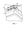
- FIG. 1 is a perspective view illustrating mounting devices for mounting a line replaceable unit to mounting apparatus in an aircraft according to an embodiment of the present invention
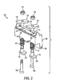
- FIG. 2 is an exploded perspective view illustrating further details of a mounting device as shown in FIG. 1 ;
- FIG. 3 is a top perspective view showing the mounting devices of FIGs. 1 and 2 where the clamping elements of the mounting devices are positioned to secure the line replaceable unit to the mounting apparatus according to an embodiment of the present invention
- FIG. 4 is a top perspective view showing the mounting devices of FIGs. 1 and 2 where the clamping elements of the mounting devices are positioned to release the line replaceable unit from the mounting apparatus according to an embodiment of the present invention.
- FIG. 1 illustrates a mounting device 100 for mounting a line replaceable unit (LRU) 104 to a panel 102 according to an embodiment of the present invention.
- the mounting device 100 can, for example, be about 7,6 cm (3 inches) in length by about 2,5 cm (1 inch) in height by about 1,9 cm (0,75 inches) in depth, and can be made of stainless steel, metal or any other suitable material.
- the mounting device 100 include a fixing block 106. Screws 108 pass through openings in respective visual position elements 110, and further through respective springs 112. The screws 108 further pass through respective openings 114 in the fixing block 106, and through respective clamping elements 116. Respective locking nuts 118 attach to the ends of the respective screws 108 to secure the screws 108, visual position elements 110, springs 112 and clamping elements 116 to the fixing block 106.
- the fixing block 106 further includes an opening 120 that receives a pin 122 attached to panel 102 (see FIG. 1 ) to thus secure the fixing block 106 to the panel 102.
- the clamping elements 116 each have a flange 124 that extends perpendicular to or substantially perpendicular to the respective flanges 126 of visual position elements 110.
- the fixing block 106 in this example is shown as having two openings 114, the fixing block 106 can have any suitable length, size and shape, and can include any suitable number of openings 114 and corresponding components as discussed above.
- the mounting device can be configured as mounting device 100-1 having a fixing block 106-1 having a single opening (not shown) to accommodate one clamping element 116-1 and corresponding visual position element 110-1, and their associated components similar to those discussed above with regard to clamping element 116 and visual position element 110.
- a fixing block e.g., fixing block 106-1) can be configured to allow a wire or power cord 130 to pass therethrough, or to accommodate other components that can be used with the line replaceable unit 104.
- the clamping elements 116 and 116-1 are oriented as also shown in FIGs. 1-3 .
- the flanges 124 and 124-1 thus extend over the surface of the line replaceable unit 104 and secure the line replaceable unit 104 to the panel 102.
- a screwdriver or Allen wrench to rotate each of the visual position elements 110 and 110-1 by 90 degrees or about 90 degrees in the direction of arrow A, so that their flanges 126 and 126-1 extend outwardly from slots 128 and 128-1 in fixing blocks 106 and 106-1 as shown in FIG. 4 .
- clamping elements 116 and 116-1 also are rotated by 90 degrees or about 90 degrees such that their flanges release the outer surface of the line replaceable unit 104 and extend parallel or substantially parallel with the length of fixing blocks 106 and 106-1. Hence, line replaceable unit 104 can be easily removed from the panel 102.
Landscapes
- Engineering & Computer Science (AREA)
- General Engineering & Computer Science (AREA)
- Microelectronics & Electronic Packaging (AREA)
- Mechanical Engineering (AREA)
- Fittings On The Vehicle Exterior For Carrying Loads, And Devices For Holding Or Mounting Articles (AREA)
- Automatic Assembly (AREA)
- Connection Of Plates (AREA)
Abstract
Description
- The present invention relates to a mounting device such as known from
GB2210839 - Certain aircraft, such as an Airbus, have mounting rails or other apparatus for mounting line replaceable units (LRUs) in the aircraft. Certain devices for attaching an LRU to the mounting rails or mounting apparatus can bind and not allow for easy removal of the LRU from the rails or mounting apparatus.
- Objects, advantages and novel features of the invention will be more readily appreciated from the following detailed description when read in conjunction with the accompanying drawings, in which:
-
FIG. 1 is a perspective view illustrating mounting devices for mounting a line replaceable unit to mounting apparatus in an aircraft according to an embodiment of the present invention; -
FIG. 2 is an exploded perspective view illustrating further details of a mounting device as shown inFIG. 1 ; -
FIG. 3 is a top perspective view showing the mounting devices ofFIGs. 1 and2 where the clamping elements of the mounting devices are positioned to secure the line replaceable unit to the mounting apparatus according to an embodiment of the present invention; and -
FIG. 4 is a top perspective view showing the mounting devices ofFIGs. 1 and2 where the clamping elements of the mounting devices are positioned to release the line replaceable unit from the mounting apparatus according to an embodiment of the present invention. - As described in detail below, the present invention relates to a mounting device that provides for easy installation and removal of a line replaceable unit from overhead mounting apparatus in an aircraft.
FIG. 1 illustrates amounting device 100 for mounting a line replaceable unit (LRU) 104 to apanel 102 according to an embodiment of the present invention. Themounting device 100 can, for example, be about 7,6 cm (3 inches) in length by about 2,5 cm (1 inch) in height by about 1,9 cm (0,75 inches) in depth, and can be made of stainless steel, metal or any other suitable material. - As shown in more detail in
FIG. 2 , themounting device 100 include afixing block 106. Screws 108 pass through openings in respectivevisual position elements 110, and further throughrespective springs 112. Thescrews 108 further pass throughrespective openings 114 in thefixing block 106, and throughrespective clamping elements 116.Respective locking nuts 118 attach to the ends of therespective screws 108 to secure thescrews 108,visual position elements 110,springs 112 andclamping elements 116 to thefixing block 106. - The
fixing block 106 further includes anopening 120 that receives apin 122 attached to panel 102 (seeFIG. 1 ) to thus secure thefixing block 106 to thepanel 102. It can be appreciated fromFIGs. 1 and2 that theclamping elements 116 each have aflange 124 that extends perpendicular to or substantially perpendicular to therespective flanges 126 ofvisual position elements 110. - In addition, although the
fixing block 106 in this example is shown as having twoopenings 114, thefixing block 106 can have any suitable length, size and shape, and can include any suitable number ofopenings 114 and corresponding components as discussed above. For example, as shown inFIGs. 1 ,3 and4 , the mounting device can be configured as mounting device 100-1 having a fixing block 106-1 having a single opening (not shown) to accommodate one clamping element 116-1 and corresponding visual position element 110-1, and their associated components similar to those discussed above with regard toclamping element 116 andvisual position element 110. Also, a fixing block (e.g., fixing block 106-1) can be configured to allow a wire orpower cord 130 to pass therethrough, or to accommodate other components that can be used with the linereplaceable unit 104. - When the
visual position elements 110 and 110-1 are oriented as shown inFIGs. 1-3 , theclamping elements 116 and 116-1 are oriented as also shown inFIGs. 1-3 . Theflanges 124 and 124-1 thus extend over the surface of the linereplaceable unit 104 and secure the linereplaceable unit 104 to thepanel 102. To remove the linereplaceable unit 104, one can use, for example, a screwdriver or Allen wrench to rotate each of thevisual position elements 110 and 110-1 by 90 degrees or about 90 degrees in the direction of arrow A, so that theirflanges 126 and 126-1 extend outwardly fromslots 128 and 128-1 infixing blocks 106 and 106-1 as shown inFIG. 4 . In this event,clamping elements 116 and 116-1 also are rotated by 90 degrees or about 90 degrees such that their flanges release the outer surface of the linereplaceable unit 104 and extend parallel or substantially parallel with the length offixing blocks 106 and 106-1. Hence, linereplaceable unit 104 can be easily removed from thepanel 102. - Although only a few exemplary embodiments of the present invention have been described in detail above, those skilled in the art will readily appreciate that many modifications are possible in the exemplary embodiments without materially departing from the scope of the claims.
Claims (13)
- An apparatus (100) for mounting a device into a vehicle, the apparatus (100) comprising:a fixing block (106) being securable to a vehicle component (102), the fixing block (106) having a least one opening (114) therein;at least one assembly comprising:a shaft portion (108);a clamping element (116) comprising an opening; anda visual position element (110) comprising an opening, wherein the visual position element orientation indicates an orientation of the clamping element (116),the shaft portion (108) passing through the opening in the fixing block (106), the clamping element (116), and the visual position element (110), wherein the clamping element (116) and the visual position element (110) are axially displaced along the shaft portion (108), andthe assembly being operable such that:the clamping element (116) secures the device to a component of the vehicle when positioned in a first position, andreleases the device when positioned in a second position, andthe visual position element (110) provides an indication of whether the clamping element (116) is in the first or second position,the apparatus being characterized in that:a) the fixing block (106) further includes another opening for receiving a mounting component that mounts the fixing block (106) to the component of the vehicle; andb) the fixing block (106) further includes at least one slot, substantially aligned with said at least one opening, such that a portion of the visual position element protrudes from the slot when the clamping element (116) is in the second position.
- An apparatus as claimed in claim 1, wherein:the assembly rotates about an axis of the shaft portion (108) to move the clamping element (116) between the first and second positions.
- An apparatus as claimed in claim 1, wherein:the fixing block (106) includes a plurality of said openings; andthe apparatus includes a plurality of said assemblies, each comprising a respective shaft portion (108), a respective clamping element (116) and a respective visual position element (110), with the respective shaft portion (108) passing through a respective one of the openings.
- An apparatus as claimed in claim 1, wherein:the assembly includes a spring (112), positioned about the shaft portion (108) between the clamping element (116) and visual position element (106) to provide an urging force which urges the clamping element (116) and visual position element (110) away from each other.
- An apparatus as claimed in claim 1, wherein:the visual position element (110) has a length that extends in a direction substantially normal to a direction in which a length of the clamping element (116) extends when the visual position element (110) and clamping element (116) are coupled to the shaft portion(108).
- An apparatus as claimed in claim 2, wherein:the visual position element (110) and the clamping element (116) rotate in unison about the axis of the shaft portion (108) when the clamping element (116) is moved between the first and second positions.
- An apparatus as claimed in claim 1, wherein:the shaft portion (108) includes an end having a recess therein, for receiving a device which is operable to rotate the shaft portion (108) between the first and second positions.
- A method for mounting a device into a vehicle, the method comprising:providing a fixing block (106) being securable to a vehicle component (102), the fixing block (106) having a least one opening therein, and at least one assembly comprising a shaft portion (108), a clamping element (116) comprising an opening, and a visual position element (110) comprising an opening, wherein the visual position element orientation indicates an orientation of the clamping element (116), with the shaft portion (108) passing through the opening in the fixing block (106), the clamping element (116), and the visual position element (110), wherein the clamping element (116) and the visual position element (110) are axially displaced along the shaft portion (108); andoperating the assembly such that the clamping element (116) secures the device to a component of the vehicle when positioned in a first position, and releases the device when positioned in a second position, and the visual position element (110) provides an indication of whether the clamping element (116) is in the first or second position;
wherein:the fixing block (106) further includes another opening; and, the method is characterized by comprising:inserting a mounting component into said another opening to mount the fixing block (106) to the component of the vehicle. - A method as claimed in claim 8, wherein:the fixing block (106) further includes at least one slot, substantially aligned with said at least one opening; andthe operating further comprises moving the visual position element (110) such that a portion of the visual position element (110) protrudes from the slot when the clamping element (116) is in the second position.
- A method as claimed in claim 8, wherein:the operating comprises rotating the assembly about an axis of the shaft portion (108) to move the clamping element (116) between the first and second positions.
- A method as claimed in claim 8, wherein:the fixing block (106) includes a plurality of said openings;the apparatus includes a plurality of said assemblies, each comprising a respective shaft portion (108), a respective clamping element (116) and a respective visual position element (110), with the respective shaft portion (108) passing through a respective one of the openings; andthe operating comprises operating each of the assemblies such that its respective clamping element (116) secures the device to a component of the vehicle when positioned in a first position, and releases the device when positioned in a second position, and its respective visual position element (110) provides an indication of whether the respective clamping element (116) is in the first or second position.
- A method as claimed in claim 8, wherein:the assembly includes a spring (112), positioned about the shaft portion (108) between the clamping element (116) and visual position element (110) to provide an urging force which urges the clamping element (116) and visual position element (110) away from each other.
- A method as claimed in claim 8, wherein:the shaft portion (108) includes an end having a recess therein; andthe operating comprises inserting a device into the recess and manipulating the second device to rotate the shaft portion (108) between the first and second positions.
Applications Claiming Priority (2)
| Application Number | Priority Date | Filing Date | Title |
|---|---|---|---|
| US85535106P | 2006-10-30 | 2006-10-30 | |
| PCT/US2007/022898 WO2008079181A2 (en) | 2006-10-30 | 2007-10-30 | Mounting device for a line replaceable unit in an aircraft and a method for using the same |
Publications (3)
| Publication Number | Publication Date |
|---|---|
| EP2078128A2 EP2078128A2 (en) | 2009-07-15 |
| EP2078128A4 EP2078128A4 (en) | 2010-12-22 |
| EP2078128B1 true EP2078128B1 (en) | 2012-06-13 |
Family
ID=39563070
Family Applications (1)
| Application Number | Title | Priority Date | Filing Date |
|---|---|---|---|
| EP20070872191 Not-in-force EP2078128B1 (en) | 2006-10-30 | 2007-10-30 | Mounting device for a line replaceable unit in an aircraft and a method for using the same |
Country Status (6)
| Country | Link |
|---|---|
| US (1) | US7942459B2 (en) |
| EP (1) | EP2078128B1 (en) |
| JP (1) | JP2010508192A (en) |
| BR (1) | BRPI0717857A2 (en) |
| CA (1) | CA2664808A1 (en) |
| WO (1) | WO2008079181A2 (en) |
Families Citing this family (11)
| Publication number | Priority date | Publication date | Assignee | Title |
|---|---|---|---|---|
| WO2008033870A2 (en) | 2006-09-11 | 2008-03-20 | Lumexis Corporation | Fiber-to-the-seat (ftts) fiber distribution system |
| US8888423B2 (en) * | 2008-10-21 | 2014-11-18 | Airbus Operations Gmbh | Attachment structure, attachment device and attachment system for attaching an equipment component in an aircraft |
| US8659990B2 (en) | 2009-08-06 | 2014-02-25 | Lumexis Corporation | Serial networking fiber-to-the-seat inflight entertainment system |
| WO2011020071A1 (en) | 2009-08-14 | 2011-02-17 | Lumexis Corp. | Video display unit docking assembly for fiber-to-the-screen inflight entertainment system |
| WO2011022708A1 (en) | 2009-08-20 | 2011-02-24 | Lumexis Corp. | Serial networking fiber optic inflight entertainment system network configuration |
| US8727686B2 (en) | 2012-03-23 | 2014-05-20 | B/E Aerospace, Inc. | Device for attaching an aircraft monument |
| US9599138B2 (en) | 2012-03-28 | 2017-03-21 | B/E Aerospace, Inc. | Aircraft monument integrated attachment device |
| CN104118567A (en) * | 2013-04-24 | 2014-10-29 | 哈尔滨飞机工业集团有限责任公司 | Aircraft instrument panel control crank pin |
| AU2016203016B2 (en) * | 2015-05-14 | 2020-04-02 | Alstom Holdings | System, apparatus and method for mounting a device |
| US9758233B2 (en) * | 2015-08-31 | 2017-09-12 | The Boeing Company | Support system having a crown integration panel (CIP) |
| CN110561496B (en) * | 2019-08-28 | 2024-03-19 | 龙岩学院 | A connecting device for flying manipulator installs and dismantles fast |
Family Cites Families (22)
| Publication number | Priority date | Publication date | Assignee | Title |
|---|---|---|---|---|
| US362152A (en) * | 1887-05-03 | Fastener for meeting-rails of sashes | ||
| US3123418A (en) * | 1964-03-03 | Chassis unit insert tightening-extract device | ||
| US1357864A (en) * | 1919-11-24 | 1920-11-02 | Henry H Harrington | Fastening device for closures |
| US1876115A (en) * | 1927-12-30 | 1932-09-06 | Walter R Way | Lock |
| US2269264A (en) * | 1941-03-04 | 1942-01-06 | Haim Albert | Swing lock fastener |
| US2525217A (en) * | 1949-07-06 | 1950-10-10 | Glitsch Engineering Company | Manway clamp |
| US2634146A (en) * | 1951-10-23 | 1953-04-07 | Jandor Inc | Window lock |
| US2772906A (en) * | 1953-10-26 | 1956-12-04 | Bell Aircraft Corp | Lock fastener |
| US2762473A (en) * | 1955-03-25 | 1956-09-11 | Gen Electric | Fastening device |
| US5046340A (en) * | 1984-04-18 | 1991-09-10 | The Eastern Company | Latch and lock assemblies with spring-biased pivot bolts |
| GB2210839B (en) * | 1985-10-30 | 1990-03-14 | Gen Electric | Spacecraft structure for orbital assembly and servicing |
| US4926287A (en) * | 1989-03-23 | 1990-05-15 | The United States Of America As Represented By The Secretary Of The Air Force | Spring loaded hand operated extraction/insertion line replaceable module (LRM) lever |
| US5172944A (en) * | 1991-11-27 | 1992-12-22 | Federal-Hoffman, Inc. | Multiple point cam-pinion door latch |
| DE9308516U1 (en) * | 1992-07-16 | 1993-08-05 | Geberit Ag, Jona, St.Gallen | Connection plate on a support frame |
| US5630632A (en) * | 1994-12-07 | 1997-05-20 | Federal-Hoffman, Inc. | Quarter turn latch |
| US5887916A (en) * | 1997-09-25 | 1999-03-30 | Kason Industries, Inc. | Safety door latch for pressurized ovens |
| US6123373A (en) * | 1997-10-30 | 2000-09-26 | Teac Corporation | Lock device having an improved lock member |
| US6357804B1 (en) * | 1999-12-13 | 2002-03-19 | General Electric Company | Door latch for electrical equipment enclosure |
| US6676176B1 (en) * | 2000-09-29 | 2004-01-13 | Siemens Energy & Automation | Enclosure for industrial controls |
| US7296831B2 (en) * | 2003-09-03 | 2007-11-20 | Paul Generowicz | Window lock keeper |
| US7100951B2 (en) * | 2004-08-18 | 2006-09-05 | Tyrone Marine Hardware Co., Ltd. | Water gate locker |
| US7699365B2 (en) * | 2005-10-19 | 2010-04-20 | Vision Industries Group, Inc. | Sash lock with condition signal |
-
2007
- 2007-10-30 US US11/978,815 patent/US7942459B2/en not_active Expired - Fee Related
- 2007-10-30 CA CA 2664808 patent/CA2664808A1/en not_active Abandoned
- 2007-10-30 BR BRPI0717857-3A2A patent/BRPI0717857A2/en not_active Application Discontinuation
- 2007-10-30 EP EP20070872191 patent/EP2078128B1/en not_active Not-in-force
- 2007-10-30 JP JP2009534699A patent/JP2010508192A/en active Pending
- 2007-10-30 WO PCT/US2007/022898 patent/WO2008079181A2/en active Application Filing
Also Published As
| Publication number | Publication date |
|---|---|
| EP2078128A2 (en) | 2009-07-15 |
| JP2010508192A (en) | 2010-03-18 |
| CA2664808A1 (en) | 2008-07-03 |
| US7942459B2 (en) | 2011-05-17 |
| WO2008079181A3 (en) | 2008-08-28 |
| US20080237440A1 (en) | 2008-10-02 |
| WO2008079181A2 (en) | 2008-07-03 |
| EP2078128A4 (en) | 2010-12-22 |
| BRPI0717857A2 (en) | 2013-10-29 |
Similar Documents
| Publication | Publication Date | Title |
|---|---|---|
| EP2078128B1 (en) | Mounting device for a line replaceable unit in an aircraft and a method for using the same | |
| US7992950B2 (en) | Method for installing a slide assembly for a computer server using dual flat springs | |
| EP3895442B1 (en) | Device for installation and removal of a ceiling speaker system | |
| US6040980A (en) | Disk drive to chassis mounting apparatus and method | |
| US20030063960A1 (en) | Rack mount panel fastener with interchangeable thread size | |
| CA3130637C (en) | Systems, apparatuses, and methods for securing screen assemblies | |
| US20140033496A1 (en) | Antenna mounting systems and methods | |
| EP3529996B1 (en) | Device for installation and removal of a ceiling speaker system | |
| EP1734640B1 (en) | Device for fixing an electrical apparatus to an electric motor | |
| US20120326002A1 (en) | Mounting apparatus for fan module | |
| US8020835B2 (en) | Device for installing and removing high insertion force modules | |
| US20020096980A1 (en) | Circuit board retaining assembly and method for use | |
| MXPA03002429A (en) | Rotor positioning system and indexation of an impact mill. | |
| US6618263B1 (en) | Quick release hold-down for PCI/AGP cards | |
| US20160073523A1 (en) | Fixation Bracket and Control Device | |
| CA2071449C (en) | Universal hold-down assembly for pump assemblies and the like | |
| CN107548329B (en) | Electric tool with the throat sheet with cam | |
| CN200964336Y (en) | Locking apparatus for van protection arm | |
| DE10033598C1 (en) | Electric wall socket or switch installation device has 2 spaced screw chucks adjusted for matching spacing of socket or switch screw fixings | |
| EP3112703B1 (en) | Diaper pin vibration damper | |
| CN106944844B (en) | Locking device, expansion rod and pipe fitting processing device | |
| EP2789907A1 (en) | Lighting device and means for fixing same to a support surface | |
| CN219937826U (en) | Cable positioning assembly and cable positioning device | |
| JPS63502572A (en) | extraction tool | |
| CN215543970U (en) | Bending device |
Legal Events
| Date | Code | Title | Description |
|---|---|---|---|
| PUAI | Public reference made under article 153(3) epc to a published international application that has entered the european phase |
Free format text: ORIGINAL CODE: 0009012 |
|
| 17P | Request for examination filed |
Effective date: 20090325 |
|
| AK | Designated contracting states |
Kind code of ref document: A2 Designated state(s): AT BE BG CH CY CZ DE DK EE ES FI FR GB GR HU IE IS IT LI LT LU LV MC MT NL PL PT RO SE SI SK TR |
|
| DAX | Request for extension of the european patent (deleted) | ||
| A4 | Supplementary search report drawn up and despatched |
Effective date: 20101124 |
|
| RIC1 | Information provided on ipc code assigned before grant |
Ipc: F16B 1/00 20060101ALI20101118BHEP Ipc: E05C 3/14 20060101AFI20090330BHEP |
|
| 17Q | First examination report despatched |
Effective date: 20110801 |
|
| GRAP | Despatch of communication of intention to grant a patent |
Free format text: ORIGINAL CODE: EPIDOSNIGR1 |
|
| GRAS | Grant fee paid |
Free format text: ORIGINAL CODE: EPIDOSNIGR3 |
|
| GRAA | (expected) grant |
Free format text: ORIGINAL CODE: 0009210 |
|
| AK | Designated contracting states |
Kind code of ref document: B1 Designated state(s): AT BE BG CH CY CZ DE DK EE ES FI FR GB GR HU IE IS IT LI LT LU LV MC MT NL PL PT RO SE SI SK TR |
|
| REG | Reference to a national code |
Ref country code: GB Ref legal event code: FG4D |
|
| REG | Reference to a national code |
Ref country code: AT Ref legal event code: REF Ref document number: 562107 Country of ref document: AT Kind code of ref document: T Effective date: 20120615 Ref country code: CH Ref legal event code: EP |
|
| REG | Reference to a national code |
Ref country code: IE Ref legal event code: FG4D |
|
| REG | Reference to a national code |
Ref country code: DE Ref legal event code: R096 Ref document number: 602007023447 Country of ref document: DE Effective date: 20120809 |
|
| REG | Reference to a national code |
Ref country code: NL Ref legal event code: VDEP Effective date: 20120613 |
|
| PG25 | Lapsed in a contracting state [announced via postgrant information from national office to epo] |
Ref country code: CY Free format text: LAPSE BECAUSE OF FAILURE TO SUBMIT A TRANSLATION OF THE DESCRIPTION OR TO PAY THE FEE WITHIN THE PRESCRIBED TIME-LIMIT Effective date: 20120613 Ref country code: FI Free format text: LAPSE BECAUSE OF FAILURE TO SUBMIT A TRANSLATION OF THE DESCRIPTION OR TO PAY THE FEE WITHIN THE PRESCRIBED TIME-LIMIT Effective date: 20120613 Ref country code: LT Free format text: LAPSE BECAUSE OF FAILURE TO SUBMIT A TRANSLATION OF THE DESCRIPTION OR TO PAY THE FEE WITHIN THE PRESCRIBED TIME-LIMIT Effective date: 20120613 Ref country code: SE Free format text: LAPSE BECAUSE OF FAILURE TO SUBMIT A TRANSLATION OF THE DESCRIPTION OR TO PAY THE FEE WITHIN THE PRESCRIBED TIME-LIMIT Effective date: 20120613 |
|
| REG | Reference to a national code |
Ref country code: AT Ref legal event code: MK05 Ref document number: 562107 Country of ref document: AT Kind code of ref document: T Effective date: 20120613 |
|
| REG | Reference to a national code |
Ref country code: LT Ref legal event code: MG4D Effective date: 20120613 |
|
| PG25 | Lapsed in a contracting state [announced via postgrant information from national office to epo] |
Ref country code: GR Free format text: LAPSE BECAUSE OF FAILURE TO SUBMIT A TRANSLATION OF THE DESCRIPTION OR TO PAY THE FEE WITHIN THE PRESCRIBED TIME-LIMIT Effective date: 20120914 Ref country code: SI Free format text: LAPSE BECAUSE OF FAILURE TO SUBMIT A TRANSLATION OF THE DESCRIPTION OR TO PAY THE FEE WITHIN THE PRESCRIBED TIME-LIMIT Effective date: 20120613 Ref country code: LV Free format text: LAPSE BECAUSE OF FAILURE TO SUBMIT A TRANSLATION OF THE DESCRIPTION OR TO PAY THE FEE WITHIN THE PRESCRIBED TIME-LIMIT Effective date: 20120613 |
|
| PG25 | Lapsed in a contracting state [announced via postgrant information from national office to epo] |
Ref country code: SK Free format text: LAPSE BECAUSE OF FAILURE TO SUBMIT A TRANSLATION OF THE DESCRIPTION OR TO PAY THE FEE WITHIN THE PRESCRIBED TIME-LIMIT Effective date: 20120613 Ref country code: CZ Free format text: LAPSE BECAUSE OF FAILURE TO SUBMIT A TRANSLATION OF THE DESCRIPTION OR TO PAY THE FEE WITHIN THE PRESCRIBED TIME-LIMIT Effective date: 20120613 Ref country code: BE Free format text: LAPSE BECAUSE OF FAILURE TO SUBMIT A TRANSLATION OF THE DESCRIPTION OR TO PAY THE FEE WITHIN THE PRESCRIBED TIME-LIMIT Effective date: 20120613 Ref country code: EE Free format text: LAPSE BECAUSE OF FAILURE TO SUBMIT A TRANSLATION OF THE DESCRIPTION OR TO PAY THE FEE WITHIN THE PRESCRIBED TIME-LIMIT Effective date: 20120613 Ref country code: RO Free format text: LAPSE BECAUSE OF FAILURE TO SUBMIT A TRANSLATION OF THE DESCRIPTION OR TO PAY THE FEE WITHIN THE PRESCRIBED TIME-LIMIT Effective date: 20120613 Ref country code: IS Free format text: LAPSE BECAUSE OF FAILURE TO SUBMIT A TRANSLATION OF THE DESCRIPTION OR TO PAY THE FEE WITHIN THE PRESCRIBED TIME-LIMIT Effective date: 20121013 Ref country code: AT Free format text: LAPSE BECAUSE OF FAILURE TO SUBMIT A TRANSLATION OF THE DESCRIPTION OR TO PAY THE FEE WITHIN THE PRESCRIBED TIME-LIMIT Effective date: 20120613 |
|
| PG25 | Lapsed in a contracting state [announced via postgrant information from national office to epo] |
Ref country code: PT Free format text: LAPSE BECAUSE OF FAILURE TO SUBMIT A TRANSLATION OF THE DESCRIPTION OR TO PAY THE FEE WITHIN THE PRESCRIBED TIME-LIMIT Effective date: 20121015 Ref country code: PL Free format text: LAPSE BECAUSE OF FAILURE TO SUBMIT A TRANSLATION OF THE DESCRIPTION OR TO PAY THE FEE WITHIN THE PRESCRIBED TIME-LIMIT Effective date: 20120613 Ref country code: IT Free format text: LAPSE BECAUSE OF FAILURE TO SUBMIT A TRANSLATION OF THE DESCRIPTION OR TO PAY THE FEE WITHIN THE PRESCRIBED TIME-LIMIT Effective date: 20120613 |
|
| PGFP | Annual fee paid to national office [announced via postgrant information from national office to epo] |
Ref country code: GB Payment date: 20121025 Year of fee payment: 6 |
|
| PG25 | Lapsed in a contracting state [announced via postgrant information from national office to epo] |
Ref country code: NL Free format text: LAPSE BECAUSE OF FAILURE TO SUBMIT A TRANSLATION OF THE DESCRIPTION OR TO PAY THE FEE WITHIN THE PRESCRIBED TIME-LIMIT Effective date: 20120613 |
|
| PLBE | No opposition filed within time limit |
Free format text: ORIGINAL CODE: 0009261 |
|
| STAA | Information on the status of an ep patent application or granted ep patent |
Free format text: STATUS: NO OPPOSITION FILED WITHIN TIME LIMIT |
|
| PG25 | Lapsed in a contracting state [announced via postgrant information from national office to epo] |
Ref country code: DK Free format text: LAPSE BECAUSE OF FAILURE TO SUBMIT A TRANSLATION OF THE DESCRIPTION OR TO PAY THE FEE WITHIN THE PRESCRIBED TIME-LIMIT Effective date: 20120613 Ref country code: ES Free format text: LAPSE BECAUSE OF FAILURE TO SUBMIT A TRANSLATION OF THE DESCRIPTION OR TO PAY THE FEE WITHIN THE PRESCRIBED TIME-LIMIT Effective date: 20120924 |
|
| 26N | No opposition filed |
Effective date: 20130314 |
|
| PG25 | Lapsed in a contracting state [announced via postgrant information from national office to epo] |
Ref country code: MC Free format text: LAPSE BECAUSE OF NON-PAYMENT OF DUE FEES Effective date: 20121031 |
|
| REG | Reference to a national code |
Ref country code: CH Ref legal event code: PL |
|
| REG | Reference to a national code |
Ref country code: DE Ref legal event code: R097 Ref document number: 602007023447 Country of ref document: DE Effective date: 20130314 |
|
| PG25 | Lapsed in a contracting state [announced via postgrant information from national office to epo] |
Ref country code: LI Free format text: LAPSE BECAUSE OF NON-PAYMENT OF DUE FEES Effective date: 20121031 Ref country code: BG Free format text: LAPSE BECAUSE OF FAILURE TO SUBMIT A TRANSLATION OF THE DESCRIPTION OR TO PAY THE FEE WITHIN THE PRESCRIBED TIME-LIMIT Effective date: 20120913 Ref country code: CH Free format text: LAPSE BECAUSE OF NON-PAYMENT OF DUE FEES Effective date: 20121031 |
|
| REG | Reference to a national code |
Ref country code: IE Ref legal event code: MM4A |
|
| PG25 | Lapsed in a contracting state [announced via postgrant information from national office to epo] |
Ref country code: IE Free format text: LAPSE BECAUSE OF NON-PAYMENT OF DUE FEES Effective date: 20121030 |
|
| PG25 | Lapsed in a contracting state [announced via postgrant information from national office to epo] |
Ref country code: MT Free format text: LAPSE BECAUSE OF FAILURE TO SUBMIT A TRANSLATION OF THE DESCRIPTION OR TO PAY THE FEE WITHIN THE PRESCRIBED TIME-LIMIT Effective date: 20120613 |
|
| PGFP | Annual fee paid to national office [announced via postgrant information from national office to epo] |
Ref country code: FR Payment date: 20131017 Year of fee payment: 7 Ref country code: DE Payment date: 20131029 Year of fee payment: 7 |
|
| PG25 | Lapsed in a contracting state [announced via postgrant information from national office to epo] |
Ref country code: TR Free format text: LAPSE BECAUSE OF FAILURE TO SUBMIT A TRANSLATION OF THE DESCRIPTION OR TO PAY THE FEE WITHIN THE PRESCRIBED TIME-LIMIT Effective date: 20120613 |
|
| PG25 | Lapsed in a contracting state [announced via postgrant information from national office to epo] |
Ref country code: LU Free format text: LAPSE BECAUSE OF NON-PAYMENT OF DUE FEES Effective date: 20121030 |
|
| GBPC | Gb: european patent ceased through non-payment of renewal fee |
Effective date: 20131030 |
|
| PG25 | Lapsed in a contracting state [announced via postgrant information from national office to epo] |
Ref country code: GB Free format text: LAPSE BECAUSE OF NON-PAYMENT OF DUE FEES Effective date: 20131030 Ref country code: HU Free format text: LAPSE BECAUSE OF FAILURE TO SUBMIT A TRANSLATION OF THE DESCRIPTION OR TO PAY THE FEE WITHIN THE PRESCRIBED TIME-LIMIT Effective date: 20071030 |
|
| REG | Reference to a national code |
Ref country code: DE Ref legal event code: R119 Ref document number: 602007023447 Country of ref document: DE |
|
| PG25 | Lapsed in a contracting state [announced via postgrant information from national office to epo] |
Ref country code: DE Free format text: LAPSE BECAUSE OF NON-PAYMENT OF DUE FEES Effective date: 20150501 |
|
| REG | Reference to a national code |
Ref country code: FR Ref legal event code: ST Effective date: 20150630 |
|
| PG25 | Lapsed in a contracting state [announced via postgrant information from national office to epo] |
Ref country code: FR Free format text: LAPSE BECAUSE OF NON-PAYMENT OF DUE FEES Effective date: 20141031 |