EP2077691A2 - Method and apparatus for performing buffer status reporting - Google Patents
Method and apparatus for performing buffer status reporting Download PDFInfo
- Publication number
- EP2077691A2 EP2077691A2 EP09000013A EP09000013A EP2077691A2 EP 2077691 A2 EP2077691 A2 EP 2077691A2 EP 09000013 A EP09000013 A EP 09000013A EP 09000013 A EP09000013 A EP 09000013A EP 2077691 A2 EP2077691 A2 EP 2077691A2
- Authority
- EP
- European Patent Office
- Prior art keywords
- logic channel
- channel group
- control element
- short
- format
- Prior art date
- Legal status (The legal status is an assumption and is not a legal conclusion. Google has not performed a legal analysis and makes no representation as to the accuracy of the status listed.)
- Granted
Links
- 239000000872 buffer Substances 0.000 title claims abstract description 43
- 238000000034 method Methods 0.000 title claims abstract description 23
- 238000004891 communication Methods 0.000 claims abstract description 33
- 238000010586 diagram Methods 0.000 description 7
- 230000005540 biological transmission Effects 0.000 description 3
- 230000006870 function Effects 0.000 description 2
- 230000007774 longterm Effects 0.000 description 2
- 230000001419 dependent effect Effects 0.000 description 1
- 238000011161 development Methods 0.000 description 1
- 230000018109 developmental process Effects 0.000 description 1
Images

Classifications
-
- H—ELECTRICITY
- H04—ELECTRIC COMMUNICATION TECHNIQUE
- H04W—WIRELESS COMMUNICATION NETWORKS
- H04W28/00—Network traffic management; Network resource management
- H04W28/02—Traffic management, e.g. flow control or congestion control
- H04W28/06—Optimizing the usage of the radio link, e.g. header compression, information sizing, discarding information
- H04W28/065—Optimizing the usage of the radio link, e.g. header compression, information sizing, discarding information using assembly or disassembly of packets
-
- H—ELECTRICITY
- H04—ELECTRIC COMMUNICATION TECHNIQUE
- H04W—WIRELESS COMMUNICATION NETWORKS
- H04W88/00—Devices specially adapted for wireless communication networks, e.g. terminals, base stations or access point devices
- H04W88/02—Terminal devices
-
- H—ELECTRICITY
- H04—ELECTRIC COMMUNICATION TECHNIQUE
- H04W—WIRELESS COMMUNICATION NETWORKS
- H04W24/00—Supervisory, monitoring or testing arrangements
-
- H—ELECTRICITY
- H04—ELECTRIC COMMUNICATION TECHNIQUE
- H04W—WIRELESS COMMUNICATION NETWORKS
- H04W72/00—Local resource management
- H04W72/20—Control channels or signalling for resource management
- H04W72/21—Control channels or signalling for resource management in the uplink direction of a wireless link, i.e. towards the network
-
- H—ELECTRICITY
- H04—ELECTRIC COMMUNICATION TECHNIQUE
- H04W—WIRELESS COMMUNICATION NETWORKS
- H04W72/00—Local resource management
- H04W72/50—Allocation or scheduling criteria for wireless resources
- H04W72/56—Allocation or scheduling criteria for wireless resources based on priority criteria
- H04W72/566—Allocation or scheduling criteria for wireless resources based on priority criteria of the information or information source or recipient
- H04W72/569—Allocation or scheduling criteria for wireless resources based on priority criteria of the information or information source or recipient of the traffic information
Definitions
- the present invention relates to a method and apparatus for performing buffer status reporting according to the pre-characterizing clauses of claims 1 and 8.
- LTE system Long Term Evolution wireless communication system
- MAC Medium Access Control
- RLC Radio Link Control
- MAC provides transmission services via a plurality of logic channels.
- a user equipment (UE) performs uplink (UL) transmission
- the network can divide or map logic channels of the UE into at most four groups based on priorities, types, and so on. The priorities are corresponding to values1 to 8, and assigned by a higher layer, the radio resource control layer.
- 3GPP introduces a Buffer Status Reporting (BSR) procedure, which is used to provide the serving NB (or enhanced NB) with information about the amount of data in UL buffers of the UE.
- BSR Buffer Status Reporting
- BSR control elements can be categorized into two formats: short and long.
- a short-format BSR control element is 1-byte long, and has 8 bits, where the former 2 bits indicate one logic channel group which buffer status is being reported, and the remaining six bits indicate the amount of data available across the logic channel group.
- a long-format BSR control element is three-byte long, and utilized for reporting data amount of the UL buffers of all the logic channel groups. Detailed description of the two formats can be found in related protocol specifications, and not narrated herein.
- the network can recognized data amount of the UL buffers of all logic channel groups.
- the long-format BSR control element occupies much more bytes than the short-format BSR control element does, such that the long-format BSR control element is not suitable for the situation that the length of the MAC PDU is insufficient.
- UE can use a padding field of a MAC PDU to carry a BSR control element. If the padding field is not long enough, the short-format BSR control element is used. Since the short-format BSR control element carries information about the amount of data available across only one logical channel group, the MAC layer needs to select a logic channel group to be reported. However, the prior art does not disclose which logic channel group is corresponding to information carried by the short-format BSR control element.
- the present invention aims at providing a method and apparatus for performing buffer status reporting (BSR), for accurately deciding a logic channel group corresponding to a short-format BSR control element when performing BSR.
- BSR buffer status reporting
- the claimed method for performing buffer status reporting in a user equipment of a wireless communication system comprises forming a MAC PDU comprising a padding field with a size smaller than a first predefined value, selecting a first logic channel group from a plurality of logic channel groups of the user equipment according to priorities and data amounts of uplink buffers of the plurality of logic channel groups, carrying information about a data amount of an uplink buffer of the first logic channel group with a short-format BSR control element, and carrying the short-format BSR control element with the padding field of the MAC PDU for a network of the wireless communication system.
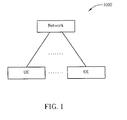
- Fig. 1 illustrates a schematic diagram of a wireless communication system 1000.
- the wireless communication system 1000 is preferably an LTE (long-term evolution) system, and is briefly composed of a network and a plurality of UEs.
- the network and the UEs are simply utilized for illustrating the structure of the wireless communication system 1000.
- the network may comprise a plurality of base stations (Node Bs), radio network controllers and so on according to actual demands, and the UEs can be devices such as mobile phones, computer systems, etc.
- FIG. 2 is a functional block diagram of a communication device 100 in a wireless communication system.
- Fig. 2 only shows an input device 102, an output device 104, a control circuit 106, a central processing unit (CPU) 108, a memory 110, a program code 112, and a transceiver 114 of the communication device 100.
- the control circuit 106 executes the program code 112 in the memory 110 through the CPU 108, thereby controlling an operation of the communication device 100.
- the communication device 100 can receive signals input by a user through the input device 102, such as a keyboard, and can output images and sounds through the output device 104, such as a monitor or speakers.
- the transceiver 114 is used to receive and transmit wireless signals, delivering received signals to the control circuit 106, and outputting signals generated by the control circuit 106 wirelessly. From a perspective of a communication protocol framework, the transceiver 114 can be seen as a portion of Layer 1, and the control circuit 106 can be utilized to realize functions of Layer 2 and Layer 3.
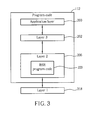
- Fig. 4 is a diagram of the program code 112 shown in Fig. 3 .
- the program code 112 includes an application layer 200, a Layer 3 202, and a Layer 2 206, and is coupled to a Layer 1 218.
- the Layer 3 202 performs resource control.
- the Layer 2 206 comprises an RLC layer and a MAC layer, and performs link control.
- the Layer 1 218 performs physical connections.
- the MAC layer of the Layer 2 206 can perform a Buffer Status Reporting (BSR) procedure, to report status of one or all logic channel groups via long-format or short-format BSR control elements.
- BSR Buffer Status Reporting
- the embodiment of the present invention provides a BSR program code 220, to decide a logic channel group corresponding to a short-format BSR control element.
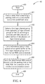
- Fig. 4 illustrates a schematic diagram of a process 40.
- the process 40 is utilized for performing BSR in a UE of the wireless communication system 1000, to decide a logic channel group corresponding to a short-format BSR control element.
- the process 40 comprises the following steps:
- the embodiment of the present invention selects a logic channel group according to priorities and data amounts of uplink buffers of all the logic channel groups, carries information about the data amount of the uplink buffer of the logic channel group with a short-format BSR control element, and returns the short-format BSR control element to the network via the MAC PDU.
- the embodiment of the present invention selects a logic channel group which has the highest priority and has an uplink buffer with data amount greater than 0 or a second predefined value, to be the target of information carried by the short-format BSR control element.
- the first predefined value is preferably corresponding to a size for carrying a long-format BSR control element, namely 4 bytes (3 bytes for the length of the long-format BSR control element, plus one byte for corresponding header).
- the embodiment of the present invention selects the logic channel group which has the highest priority and has the uplink buffer with data amount greater than 0, to be the target of information carried by the short-format BSR control element, and carries the short-format BSR control element with the MAC PDU, so as to complete the BSR procedure.
- the embodiment of the present invention selects the logic channel group which has the highest priority and has the uplink buffer with data amount greater than 0 or a predefined value, to be the target of information carried by the short-format BSR control element. For example, if the UE uses a padding field of a MAC PDU to carry a BSR control element while the padding field is not long enough to carry a long-format BSR control element, then the MAC layer uses a short-format BSR control element to report status of a logic channel group, so as to fully utilize the remaining space (namely the padding field). In such a situation, the embodiment of the present invention selects a logic channel group which has the highest priority and has an uplink buffer with data amount greater than 0 or a predefined value, to be the target of information carried by the short-format BSR control element.
- the embodiment of the present invention selects a logic channel group which has the highest priority and has an uplink buffer with data amount greater than 0 or a predefined value, to be the target of information carried by the short-format BSR control element.
Landscapes
- Engineering & Computer Science (AREA)
- Computer Networks & Wireless Communication (AREA)
- Signal Processing (AREA)
- Mobile Radio Communication Systems (AREA)
- Diaphragms For Electromechanical Transducers (AREA)
- Peptides Or Proteins (AREA)
- Small-Scale Networks (AREA)
Abstract
Description
- This application claims the benefit of
U.S. Provisional Application No. 61/018,676, filed on Jan 3, 2008 - The present invention relates to a method and apparatus for performing buffer status reporting according to the pre-characterizing clauses of
claims 1 and 8. - Long Term Evolution wireless communication system (LTE system), an advanced high-speed wireless communication system established upon the 3G mobile telecommunication system, supports only packet-switched transmission, and tends to implement both Medium Access Control (MAC) layer and Radio Link Control (RLC) layer in one single communication site, such as in Node B (NB) alone rather than in NB and RNC (Radio Network Controller) respectively, so that the system structure becomes simple.
- In LTE, MAC provides transmission services via a plurality of logic channels. To manage uplink resources, when a user equipment (UE) performs uplink (UL) transmission, the network can divide or map logic channels of the UE into at most four groups based on priorities, types, and so on. The priorities are corresponding to values1 to 8, and assigned by a higher layer, the radio resource control layer. Besides, the 3rd Generation Partnership Project, 3GPP, introduces a Buffer Status Reporting (BSR) procedure, which is used to provide the serving NB (or enhanced NB) with information about the amount of data in UL buffers of the UE.
- In the BSR procedure, UE uses a MAC PDU (Protocol Data Unit) to carry a BSR control element, so as to report information about the amount of data in the UL buffers to the network. Accordingly, the network can determine the total amount of data available across one or all logical channel groups. According to different requirements, BSR control elements can be categorized into two formats: short and long. A short-format BSR control element is 1-byte long, and has 8 bits, where the former 2 bits indicate one logic channel group which buffer status is being reported, and the remaining six bits indicate the amount of data available across the logic channel group. A long-format BSR control element is three-byte long, and utilized for reporting data amount of the UL buffers of all the logic channel groups. Detailed description of the two formats can be found in related protocol specifications, and not narrated herein.
- Via the long-format BSR control element, the network can recognized data amount of the UL buffers of all logic channel groups. However, the long-format BSR control element occupies much more bytes than the short-format BSR control element does, such that the long-format BSR control element is not suitable for the situation that the length of the MAC PDU is insufficient. For example, in some situations, UE can use a padding field of a MAC PDU to carry a BSR control element. If the padding field is not long enough, the short-format BSR control element is used. Since the short-format BSR control element carries information about the amount of data available across only one logical channel group, the MAC layer needs to select a logic channel group to be reported. However, the prior art does not disclose which logic channel group is corresponding to information carried by the short-format BSR control element.
- This in mind, the present invention aims at providing a method and apparatus for performing buffer status reporting (BSR), for accurately deciding a logic channel group corresponding to a short-format BSR control element when performing BSR.
- This is achieved by a method and apparatus for performing buffer status reporting according to
claims 1 and 8. The dependent claims pertain to corresponding further developments and improvements. - As will be seen more clearly from the detailed description following below, the claimed method for performing buffer status reporting in a user equipment of a wireless communication system comprises forming a MAC PDU comprising a padding field with a size smaller than a first predefined value, selecting a first logic channel group from a plurality of logic channel groups of the user equipment according to priorities and data amounts of uplink buffers of the plurality of logic channel groups, carrying information about a data amount of an uplink buffer of the first logic channel group with a short-format BSR control element, and carrying the short-format BSR control element with the padding field of the MAC PDU for a network of the wireless communication system.
- In the following, the invention is further illustrated by way of example, taking reference to the accompanying drawings. Thereof
-
Fig. 1 is a schematic diagram of a wireless communications system. -
Fig. 2 is a function block diagram of a wireless communications device. -
Fig. 3 is a diagram of program code ofFig. 2 . -
Fig. 4 is a flowchart of a process according to an embodiment of the present invention. - Please refer to
Fig. 1 , which illustrates a schematic diagram of awireless communication system 1000. Thewireless communication system 1000 is preferably an LTE (long-term evolution) system, and is briefly composed of a network and a plurality of UEs. InFig. 1 , the network and the UEs are simply utilized for illustrating the structure of thewireless communication system 1000. Practically, the network may comprise a plurality of base stations (Node Bs), radio network controllers and so on according to actual demands, and the UEs can be devices such as mobile phones, computer systems, etc. - Please refer to
Fig. 2 , which is a functional block diagram of acommunication device 100 in a wireless communication system. For the sake of brevity,Fig. 2 only shows aninput device 102, anoutput device 104, a control circuit 106, a central processing unit (CPU) 108, a memory 110, aprogram code 112, and atransceiver 114 of thecommunication device 100. In thecommunication device 100, the control circuit 106 executes theprogram code 112 in the memory 110 through the CPU 108, thereby controlling an operation of thecommunication device 100. Thecommunication device 100 can receive signals input by a user through theinput device 102, such as a keyboard, and can output images and sounds through theoutput device 104, such as a monitor or speakers. Thetransceiver 114 is used to receive and transmit wireless signals, delivering received signals to the control circuit 106, and outputting signals generated by the control circuit 106 wirelessly. From a perspective of a communication protocol framework, thetransceiver 114 can be seen as a portion ofLayer 1, and the control circuit 106 can be utilized to realize functions ofLayer 2 andLayer 3. - Please continue to refer to
Fig. 4 , which is a diagram of theprogram code 112 shown inFig. 3 . Theprogram code 112 includes anapplication layer 200, aLayer 3 202, and aLayer 2 206, and is coupled to aLayer 1 218. TheLayer 3 202 performs resource control. TheLayer 2 206 comprises an RLC layer and a MAC layer, and performs link control. TheLayer 1 218 performs physical connections. - In LTE, the MAC layer of the
Layer 2 206 can perform a Buffer Status Reporting (BSR) procedure, to report status of one or all logic channel groups via long-format or short-format BSR control elements. In such a situation, the embodiment of the present invention provides aBSR program code 220, to decide a logic channel group corresponding to a short-format BSR control element. Please refer toFig. 4 , which illustrates a schematic diagram of aprocess 40. Theprocess 40 is utilized for performing BSR in a UE of thewireless communication system 1000, to decide a logic channel group corresponding to a short-format BSR control element. Theprocess 40 comprises the following steps: - Step 400: Start.
- Step 401: Form a MAC PDU comprising a padding field with a size smaller than a first predefined value.
- Step 402: Select a first logic channel group from a plurality of logic channel groups of the UE according to priorities and data amounts of uplink buffers of the plurality of logic channel groups.
- Step 404: Carry information about a data amount of an uplink buffer of the first logic channel group with a short-format BSR control element.
- Step 406: Carry the short-format BSR control element with the padding field of the MAC PDU for a network of the wireless communication system.
- Step 408: End.
- According to the
process 40, when the UE performs BSR, if a corresponding MAC PDU comprises a padding field with a size smaller than a first predefined value, then the embodiment of the present invention selects a logic channel group according to priorities and data amounts of uplink buffers of all the logic channel groups, carries information about the data amount of the uplink buffer of the logic channel group with a short-format BSR control element, and returns the short-format BSR control element to the network via the MAC PDU. - Preferably, the embodiment of the present invention selects a logic channel group which has the highest priority and has an uplink buffer with data amount greater than 0 or a second predefined value, to be the target of information carried by the short-format BSR control element. Meanwhile, the first predefined value is preferably corresponding to a size for carrying a long-format BSR control element, namely 4 bytes (3 bytes for the length of the long-format BSR control element, plus one byte for corresponding header). In other words, when performing BSR, if a MAC PDU comprises remaining space (namely padding field) while the remaining space is merely enough for carry a short-format BSR control element rather than a long-format BSR control element, then the embodiment of the present invention selects the logic channel group which has the highest priority and has the uplink buffer with data amount greater than 0, to be the target of information carried by the short-format BSR control element, and carries the short-format BSR control element with the MAC PDU, so as to complete the BSR procedure.
- Therefore, when the UE performs BSR, if the remaining space of the MAC PDU is only sufficient for carrying the short-format BSR control element, the embodiment of the present invention selects the logic channel group which has the highest priority and has the uplink buffer with data amount greater than 0 or a predefined value, to be the target of information carried by the short-format BSR control element. For example, if the UE uses a padding field of a MAC PDU to carry a BSR control element while the padding field is not long enough to carry a long-format BSR control element, then the MAC layer uses a short-format BSR control element to report status of a logic channel group, so as to fully utilize the remaining space (namely the padding field). In such a situation, the embodiment of the present invention selects a logic channel group which has the highest priority and has an uplink buffer with data amount greater than 0 or a predefined value, to be the target of information carried by the short-format BSR control element.
- In summary, if the UE needs to perform BSR while the remaining space of the corresponding MAC PDU is only enough to carry a short-format BSR control element, then the embodiment of the present invention selects a logic channel group which has the highest priority and has an uplink buffer with data amount greater than 0 or a predefined value, to be the target of information carried by the short-format BSR control element.
Claims (14)
- A method for performing buffer status reporting in a user equipment of a wireless communication system comprising:forming a medium access control protocol data unit, abbreviated in MAC PDU hereinafter, comprising a padding field with a size smaller than a first predefined value (401);carrying information about a data amount of an uplink buffer of a first logic channel group with a short-format buffer status reporting, abbreviated in BSR hereinafter, control element (404); andcarrying the short-format BSR control element with the padding field of the MAC PDU for a network of the wireless communication system (406);characterized by before carrying information about the data amount of the uplink buffer of the first logic channel group with the short-format BSR control element (404), selecting the first logic channel group from a plurality of logic channel groups of the user equipment according to priorities and data amounts of uplink buffers of the plurality of logic channel groups (402).
- The method of claim 1, characterized in that a priority of the first logic channel group is higher than priorities of other logic channel groups of the plurality of logic channel groups, and the data amount of the uplink buffer of the first logic channel group is greater than 0.
- The method of claim 1, characterized in that a priority of the first logic channel group is higher than priorities of other logic channel groups of the plurality of logic channel groups, and the data amount of the uplink buffer of the first logic channel group is greater than a second predefined value.
- The method of claim 1, characterized in that the first predefined value is corresponding to a size for carrying a long-format BSR control element.
- The method of claim 1, characterized in that the short-format BSR control element comprises a single byte data composed of 8 bits, the former 2 bits indicate the first logic channel group, and the remaining 6 bits indicate the data amount of the uplink buffer of the first logic channel group.
- The method of claim 1, characterized in that a plurality of logic channels is mapped to the first logic channel group and each logical channel is assigned a priority by a higher layer.
- The method of claim 6, characterized in that a value of a priority is from 1 to 8 and the higher layer is a radio resource control layer.
- A communication device (100) utilized in a receiver of a wireless communication system for accurately performing buffer status reporting, the communication device (100) comprising:a processor (108) for executing a program code (112); anda memory (110) coupled to the processor (108) for storing the program code (112); wherein the program code (112) comprises:characterized by before carrying information about the data amount of the uplink buffer of the first logic channel group with the short-format BSR control element (404), selecting the first logic channel group from a plurality of logic channel groups of the user equipment according to priorities and data amounts of uplink buffers of the plurality of logic channel groups (402).forming a medium access control protocol data unit, abbreviated in MAC PDU hereinafter, comprising a padding field with a size smaller than a first predefined value (401);carrying information about a data amount of an uplink buffer of a first logic channel group with a short-format buffer status reporting, abbreviated in BSR hereinafter, control element (404); andcarrying the short-format BSR control element with the padding field of the MAC PDU for a network of the wireless communication system (406);
- The communication device of claim 8, characterized in that a priority of the first logic channel group is higher than priorities of other logic channel groups of the plurality of logic channel groups, and the data amount of the uplink buffer of the first logic channel group is greater than 0.
- The communication device of claim 8, characterized in that a priority of the first logic channel group is higher than priorities of other logic channel groups of the plurality of logic channel groups, and the data amount of the uplink buffer of the first logic channel group is greater than a second predefined value.
- The communication device of claim 8, characterized in that the first predefined value is corresponding to a size for carrying a long-format BSR control element.
- The communication device of claim 8, characterized in that the short-format BSR control element comprises a single byte data composed of 8 bits, the former 2 bits indicate the first logic channel group, and the remaining 6 bits indicate the data amount of the uplink buffer of the first logic channel group.
- The communication device of claim 8, characterized in that a plurality of logic channels is mapped to the first logic channel group and each logical channel is assigned a priority by a higher layer.
- The communication device of claim 13, characterized in that a value of a priority is from 1 to 8 and the higher layer is a radio resource control layer.
Applications Claiming Priority (1)
| Application Number | Priority Date | Filing Date | Title |
|---|---|---|---|
| US1867608P | 2008-01-03 | 2008-01-03 |
Publications (3)
| Publication Number | Publication Date |
|---|---|
| EP2077691A2 true EP2077691A2 (en) | 2009-07-08 |
| EP2077691A3 EP2077691A3 (en) | 2009-09-23 |
| EP2077691B1 EP2077691B1 (en) | 2010-08-18 |
Family
ID=40527010
Family Applications (1)
| Application Number | Title | Priority Date | Filing Date |
|---|---|---|---|
| EP09000013A Revoked EP2077691B1 (en) | 2008-01-03 | 2009-01-02 | Method and apparatus for performing buffer status reporting (BSR) |
Country Status (9)
| Country | Link |
|---|---|
| US (1) | US8165066B2 (en) |
| EP (1) | EP2077691B1 (en) |
| JP (1) | JP5334296B2 (en) |
| KR (1) | KR101011441B1 (en) |
| CN (1) | CN101478777B (en) |
| AT (1) | ATE478529T1 (en) |
| DE (1) | DE602009000097D1 (en) |
| ES (1) | ES2350564T3 (en) |
| TW (1) | TWI373225B (en) |
Cited By (1)
| Publication number | Priority date | Publication date | Assignee | Title |
|---|---|---|---|---|
| EP2568759A4 (en) * | 2010-05-03 | 2015-07-01 | Alcatel Lucent | METHOD AND DEVICE FOR SENDING STAMP CONDITION REPORT IN A WIRELESS NETWORK |
Families Citing this family (20)
| Publication number | Priority date | Publication date | Assignee | Title |
|---|---|---|---|---|
| ES2751715T3 (en) * | 2008-02-01 | 2020-04-01 | Optis Wireless Technology Llc | Communications terminal and base station |
| EP3048835B1 (en) | 2008-02-20 | 2020-09-30 | Amazon Technologies, Inc. | Apparatus and method for constructing a data unit that includes a buffer status report |
| CN101572913A (en) * | 2008-04-28 | 2009-11-04 | 华为技术有限公司 | Processing method and device for status report of buffer area |
| US8254326B2 (en) * | 2009-10-01 | 2012-08-28 | Htc Corporation | Method for transmitting power headroom report and buffer status report in a wireless communication system and related communication device |
| US9258088B2 (en) * | 2010-06-18 | 2016-02-09 | Acer Incorporated | Method of performing buffer status reporting and communication device thereof |
| EP2584714B1 (en) * | 2010-06-18 | 2019-05-01 | LG Electronics Inc. | Method for transmitting buffer state report from terminal in wireless communication system |
| EP2398273B1 (en) | 2010-06-18 | 2018-02-14 | Acer Incorporated | Method of handling buffer status report and communication device thereof |
| US9107214B2 (en) | 2012-01-06 | 2015-08-11 | Industrial Technology Research Institute | Method of handling hybrid automatic repeat request acknowledgement responses in wireless communication system |
| US9137781B2 (en) * | 2012-01-06 | 2015-09-15 | Industrial Technology Research Institute | Method of handling hybrid automatic repeat request resources in wireless communication system |
| KR101896440B1 (en) | 2012-05-14 | 2018-09-11 | 삼성전자 주식회사 | Method and appratus of handling the buffer status report in mobile communication system using inter-base station-carrier aggregation |
| CN104919846A (en) | 2013-01-11 | 2015-09-16 | Lg电子株式会社 | Method for reporting buffer status and communication device therefor |
| CN104081745B (en) * | 2013-01-30 | 2017-02-15 | 华为技术有限公司 | Uplink transmission method, base station, and user equipment |
| WO2015141824A1 (en) * | 2014-03-20 | 2015-09-24 | シャープ株式会社 | Terminal device, base station device, notification system, notification method, and integrated circuit |
| CN112788573B (en) * | 2015-08-12 | 2023-06-06 | Lg电子株式会社 | Method and wireless device for operation in a wireless communication system |
| CN108039934B (en) * | 2016-10-07 | 2021-04-06 | 宏达国际电子股份有限公司 | Apparatus and method for performing codec rate allocation in wireless communication system |
| WO2018227566A1 (en) * | 2017-06-16 | 2018-12-20 | Oppo广东移动通信有限公司 | Information transmission method and device |
| KR102291807B1 (en) * | 2017-06-16 | 2021-08-19 | 텔레폰악티에볼라겟엘엠에릭슨(펍) | Method and apparatus related to buffer status reporting in a wireless communication network |
| US11647417B2 (en) | 2017-10-30 | 2023-05-09 | Nokia Technologies Oy | Method, apparatus, computer program product and computer program |
| US11523301B2 (en) * | 2020-04-20 | 2022-12-06 | Qualcomm Incorporated | Physical uplink control channel with buffer status report |
| US11758513B2 (en) | 2020-04-20 | 2023-09-12 | Qualcomm Incorporated | Physical uplink control channel with uplink message short data field |
Family Cites Families (8)
| Publication number | Priority date | Publication date | Assignee | Title |
|---|---|---|---|---|
| US8189615B2 (en) * | 2004-12-23 | 2012-05-29 | Nokia Corporation | Method and apparatus for communicating scheduling information from a UE to a radio access network |
| KR20060082734A (en) | 2005-01-13 | 2006-07-19 | 삼성전자주식회사 | Method and device for efficient buffer status reporting in mobile communication system |
| KR100918743B1 (en) | 2006-01-18 | 2009-09-24 | 삼성전자주식회사 | Method and device for selecting transmission format combination in wireless communication system |
| EP1985146A4 (en) * | 2006-02-03 | 2012-01-18 | Nokia Corp | APPARATUS, METHOD, AND COMPUTER PROGRAM FOR PROVIDING THRESHOLD-BASED BUFFER STATE REPORTS FROM USER EQUIPMENT TO WIRELESS NETWORK |
| DE602006014029D1 (en) | 2006-06-21 | 2010-06-10 | Ericsson Telefon Ab L M | PROCESS AND UNIT FOR EFFICIENT REPORTING OF PLANNING INFORMATION (SCHEDULING INFORMATION) IN E |
| TW200926860A (en) * | 2007-10-29 | 2009-06-16 | Sunplus Mmobile Inc | Method for providing a buffer status report in a mobile communication network |
| MX2010004970A (en) | 2007-11-05 | 2010-07-30 | Nokia Siemens Networks Oy | Buffer status reporting system and method. |
| CN101483918B (en) * | 2008-01-08 | 2011-11-23 | 华为技术有限公司 | Buffer condition report sending method and apparatus thereof |
-
2008
- 2008-12-30 US US12/346,781 patent/US8165066B2/en active Active
- 2008-12-31 CN CN200810190376.8A patent/CN101478777B/en active Active
- 2008-12-31 TW TW097151610A patent/TWI373225B/en active
-
2009
- 2009-01-02 EP EP09000013A patent/EP2077691B1/en not_active Revoked
- 2009-01-02 ES ES09000013T patent/ES2350564T3/en active Active
- 2009-01-02 AT AT09000013T patent/ATE478529T1/en not_active IP Right Cessation
- 2009-01-02 DE DE602009000097T patent/DE602009000097D1/en active Active
- 2009-01-02 KR KR1020090000132A patent/KR101011441B1/en active Active
- 2009-01-05 JP JP2009000379A patent/JP5334296B2/en active Active
Cited By (2)
| Publication number | Priority date | Publication date | Assignee | Title |
|---|---|---|---|---|
| EP2568759A4 (en) * | 2010-05-03 | 2015-07-01 | Alcatel Lucent | METHOD AND DEVICE FOR SENDING STAMP CONDITION REPORT IN A WIRELESS NETWORK |
| US9369904B2 (en) | 2010-05-03 | 2016-06-14 | Alcatel Lucent | Method and apparatus for transmitting buffer status report in wireless network |
Also Published As
| Publication number | Publication date |
|---|---|
| US8165066B2 (en) | 2012-04-24 |
| TW200931853A (en) | 2009-07-16 |
| ATE478529T1 (en) | 2010-09-15 |
| EP2077691A3 (en) | 2009-09-23 |
| TWI373225B (en) | 2012-09-21 |
| CN101478777B (en) | 2014-07-16 |
| JP5334296B2 (en) | 2013-11-06 |
| DE602009000097D1 (en) | 2010-09-30 |
| US20090175229A1 (en) | 2009-07-09 |
| KR101011441B1 (en) | 2011-01-28 |
| JP2009165128A (en) | 2009-07-23 |
| ES2350564T3 (en) | 2011-01-25 |
| KR20090075635A (en) | 2009-07-08 |
| CN101478777A (en) | 2009-07-08 |
| EP2077691B1 (en) | 2010-08-18 |
Similar Documents
| Publication | Publication Date | Title |
|---|---|---|
| US8165066B2 (en) | Method and apparatus for performing buffer status reporting | |
| US8031658B2 (en) | Method and apparatus for performing buffer status reporting | |
| EP2134132B1 (en) | Method and apparatus for handling scheduling information report | |
| RU2405275C2 (en) | Method and system for transfer of planning information between user device and network of radio access with application of gap, which is otherwise filled with meaningless information | |
| EP1929826B1 (en) | Apparatus, method and computer program product to request a data rate increase based on ability to transmit at least one more selected data unit | |
| EP2099249B1 (en) | Method and apparatus for performing buffer status reporting | |
| EP1766878B1 (en) | Method for selecting transport format combination guaranteed qos in mobile communication system | |
| EP3451620B1 (en) | Method and apparatus for improving reception of downlink shared channel in a wireless communications system | |
| EP1971048A2 (en) | Method and apparatus for improving configurations of serving grants for a user equipment in a wireless communications system | |
| EP2634950A2 (en) | Method and Apparatus for Power Headroom Reporting | |
| CN112272388B (en) | Method and device for transmitting information | |
| EP1841265A2 (en) | Method and apparatus for handling uplink transmission start in a wireless communication system | |
| EP2107709A2 (en) | Method and apparatus of transmission time interval bundling management | |
| US20250071615A1 (en) | Data transmission method and apparatus and communication device | |
| EP2040498A1 (en) | Method for setting headers for RLC PDU segments | |
| CN104412695B (en) | A transmission channel reconfiguration method, device and system | |
| US20090279477A1 (en) | Mobile station, wireless access network apparatus, and mobile communication system | |
| EP1956769A2 (en) | Method and related apparatus for enhancing resource utility rate in a wireless communications system |
Legal Events
| Date | Code | Title | Description |
|---|---|---|---|
| PUAI | Public reference made under article 153(3) epc to a published international application that has entered the european phase |
Free format text: ORIGINAL CODE: 0009012 |
|
| 17P | Request for examination filed |
Effective date: 20090102 |
|
| AK | Designated contracting states |
Kind code of ref document: A2 Designated state(s): AT BE BG CH CY CZ DE DK EE ES FI FR GB GR HR HU IE IS IT LI LT LU LV MC MK MT NL NO PL PT RO SE SI SK TR |
|
| AX | Request for extension of the european patent |
Extension state: AL BA RS |
|
| PUAL | Search report despatched |
Free format text: ORIGINAL CODE: 0009013 |
|
| AK | Designated contracting states |
Kind code of ref document: A3 Designated state(s): AT BE BG CH CY CZ DE DK EE ES FI FR GB GR HR HU IE IS IT LI LT LU LV MC MK MT NL NO PL PT RO SE SI SK TR |
|
| AX | Request for extension of the european patent |
Extension state: AL BA RS |
|
| RIC1 | Information provided on ipc code assigned before grant |
Ipc: H04W 28/06 20090101AFI20090820BHEP |
|
| GRAP | Despatch of communication of intention to grant a patent |
Free format text: ORIGINAL CODE: EPIDOSNIGR1 |
|
| RTI1 | Title (correction) |
Free format text: METHOD AND APPARATUS FOR PERFORMING BUFFER STATUS REPORTING (BSR) |
|
| AKX | Designation fees paid |
Designated state(s): AT BE BG CH CY CZ DE DK EE ES FI FR GB GR HR HU IE IS IT LI LT LU LV MC MK MT NL NO PL PT RO SE SI SK TR |
|
| GRAS | Grant fee paid |
Free format text: ORIGINAL CODE: EPIDOSNIGR3 |
|
| GRAA | (expected) grant |
Free format text: ORIGINAL CODE: 0009210 |
|
| AK | Designated contracting states |
Kind code of ref document: B1 Designated state(s): AT BE BG CH CY CZ DE DK EE ES FI FR GB GR HR HU IE IS IT LI LT LU LV MC MK MT NL NO PL PT RO SE SI SK TR |
|
| REG | Reference to a national code |
Ref country code: GB Ref legal event code: FG4D |
|
| REG | Reference to a national code |
Ref country code: CH Ref legal event code: EP |
|
| REG | Reference to a national code |
Ref country code: NL Ref legal event code: T3 Ref country code: IE Ref legal event code: FG4D |
|
| REF | Corresponds to: |
Ref document number: 602009000097 Country of ref document: DE Date of ref document: 20100930 Kind code of ref document: P |
|
| REG | Reference to a national code |
Ref country code: SE Ref legal event code: TRGR |
|
| LTIE | Lt: invalidation of european patent or patent extension |
Effective date: 20100818 |
|
| REG | Reference to a national code |
Ref country code: ES Ref legal event code: FG2A Effective date: 20110113 |
|
| PG25 | Lapsed in a contracting state [announced via postgrant information from national office to epo] |
Ref country code: AT Free format text: LAPSE BECAUSE OF FAILURE TO SUBMIT A TRANSLATION OF THE DESCRIPTION OR TO PAY THE FEE WITHIN THE PRESCRIBED TIME-LIMIT Effective date: 20100818 Ref country code: LT Free format text: LAPSE BECAUSE OF FAILURE TO SUBMIT A TRANSLATION OF THE DESCRIPTION OR TO PAY THE FEE WITHIN THE PRESCRIBED TIME-LIMIT Effective date: 20100818 Ref country code: NO Free format text: LAPSE BECAUSE OF FAILURE TO SUBMIT A TRANSLATION OF THE DESCRIPTION OR TO PAY THE FEE WITHIN THE PRESCRIBED TIME-LIMIT Effective date: 20101118 |
|
| PG25 | Lapsed in a contracting state [announced via postgrant information from national office to epo] |
Ref country code: HR Free format text: LAPSE BECAUSE OF FAILURE TO SUBMIT A TRANSLATION OF THE DESCRIPTION OR TO PAY THE FEE WITHIN THE PRESCRIBED TIME-LIMIT Effective date: 20100818 Ref country code: SI Free format text: LAPSE BECAUSE OF FAILURE TO SUBMIT A TRANSLATION OF THE DESCRIPTION OR TO PAY THE FEE WITHIN THE PRESCRIBED TIME-LIMIT Effective date: 20100818 Ref country code: PL Free format text: LAPSE BECAUSE OF FAILURE TO SUBMIT A TRANSLATION OF THE DESCRIPTION OR TO PAY THE FEE WITHIN THE PRESCRIBED TIME-LIMIT Effective date: 20100818 Ref country code: IS Free format text: LAPSE BECAUSE OF FAILURE TO SUBMIT A TRANSLATION OF THE DESCRIPTION OR TO PAY THE FEE WITHIN THE PRESCRIBED TIME-LIMIT Effective date: 20101218 Ref country code: CY Free format text: LAPSE BECAUSE OF FAILURE TO SUBMIT A TRANSLATION OF THE DESCRIPTION OR TO PAY THE FEE WITHIN THE PRESCRIBED TIME-LIMIT Effective date: 20100818 Ref country code: BG Free format text: LAPSE BECAUSE OF FAILURE TO SUBMIT A TRANSLATION OF THE DESCRIPTION OR TO PAY THE FEE WITHIN THE PRESCRIBED TIME-LIMIT Effective date: 20101118 |
|
| PG25 | Lapsed in a contracting state [announced via postgrant information from national office to epo] |
Ref country code: GR Free format text: LAPSE BECAUSE OF FAILURE TO SUBMIT A TRANSLATION OF THE DESCRIPTION OR TO PAY THE FEE WITHIN THE PRESCRIBED TIME-LIMIT Effective date: 20101119 Ref country code: LV Free format text: LAPSE BECAUSE OF FAILURE TO SUBMIT A TRANSLATION OF THE DESCRIPTION OR TO PAY THE FEE WITHIN THE PRESCRIBED TIME-LIMIT Effective date: 20100818 Ref country code: BE Free format text: LAPSE BECAUSE OF FAILURE TO SUBMIT A TRANSLATION OF THE DESCRIPTION OR TO PAY THE FEE WITHIN THE PRESCRIBED TIME-LIMIT Effective date: 20100818 |
|
| PG25 | Lapsed in a contracting state [announced via postgrant information from national office to epo] |
Ref country code: DK Free format text: LAPSE BECAUSE OF FAILURE TO SUBMIT A TRANSLATION OF THE DESCRIPTION OR TO PAY THE FEE WITHIN THE PRESCRIBED TIME-LIMIT Effective date: 20100818 |
|
| PLBI | Opposition filed |
Free format text: ORIGINAL CODE: 0009260 |
|
| PG25 | Lapsed in a contracting state [announced via postgrant information from national office to epo] |
Ref country code: EE Free format text: LAPSE BECAUSE OF FAILURE TO SUBMIT A TRANSLATION OF THE DESCRIPTION OR TO PAY THE FEE WITHIN THE PRESCRIBED TIME-LIMIT Effective date: 20100818 Ref country code: SK Free format text: LAPSE BECAUSE OF FAILURE TO SUBMIT A TRANSLATION OF THE DESCRIPTION OR TO PAY THE FEE WITHIN THE PRESCRIBED TIME-LIMIT Effective date: 20100818 Ref country code: RO Free format text: LAPSE BECAUSE OF FAILURE TO SUBMIT A TRANSLATION OF THE DESCRIPTION OR TO PAY THE FEE WITHIN THE PRESCRIBED TIME-LIMIT Effective date: 20100818 Ref country code: CZ Free format text: LAPSE BECAUSE OF FAILURE TO SUBMIT A TRANSLATION OF THE DESCRIPTION OR TO PAY THE FEE WITHIN THE PRESCRIBED TIME-LIMIT Effective date: 20100818 |
|
| PLAX | Notice of opposition and request to file observation + time limit sent |
Free format text: ORIGINAL CODE: EPIDOSNOBS2 |
|
| 26 | Opposition filed |
Opponent name: TELEFONAKTIEBOLAGET L M ERICSSON (PUBL) Effective date: 20110518 |
|
| REG | Reference to a national code |
Ref country code: DE Ref legal event code: R026 Ref document number: 602009000097 Country of ref document: DE Effective date: 20110518 |
|
| PG25 | Lapsed in a contracting state [announced via postgrant information from national office to epo] |
Ref country code: MC Free format text: LAPSE BECAUSE OF NON-PAYMENT OF DUE FEES Effective date: 20110131 |
|
| REG | Reference to a national code |
Ref country code: IE Ref legal event code: MM4A |
|
| PLAF | Information modified related to communication of a notice of opposition and request to file observations + time limit |
Free format text: ORIGINAL CODE: EPIDOSCOBS2 |
|
| PG25 | Lapsed in a contracting state [announced via postgrant information from national office to epo] |
Ref country code: MT Free format text: LAPSE BECAUSE OF FAILURE TO SUBMIT A TRANSLATION OF THE DESCRIPTION OR TO PAY THE FEE WITHIN THE PRESCRIBED TIME-LIMIT Effective date: 20100818 |
|
| PLBB | Reply of patent proprietor to notice(s) of opposition received |
Free format text: ORIGINAL CODE: EPIDOSNOBS3 |
|
| PG25 | Lapsed in a contracting state [announced via postgrant information from national office to epo] |
Ref country code: IE Free format text: LAPSE BECAUSE OF NON-PAYMENT OF DUE FEES Effective date: 20110102 |
|
| PG25 | Lapsed in a contracting state [announced via postgrant information from national office to epo] |
Ref country code: MK Free format text: LAPSE BECAUSE OF FAILURE TO SUBMIT A TRANSLATION OF THE DESCRIPTION OR TO PAY THE FEE WITHIN THE PRESCRIBED TIME-LIMIT Effective date: 20100818 |
|
| RAP2 | Party data changed (patent owner data changed or rights of a patent transferred) |
Owner name: INNOVATIVE SONIC LIMITED |
|
| PG25 | Lapsed in a contracting state [announced via postgrant information from national office to epo] |
Ref country code: LU Free format text: LAPSE BECAUSE OF NON-PAYMENT OF DUE FEES Effective date: 20110102 |
|
| RDAF | Communication despatched that patent is revoked |
Free format text: ORIGINAL CODE: EPIDOSNREV1 |
|
| PG25 | Lapsed in a contracting state [announced via postgrant information from national office to epo] |
Ref country code: PT Free format text: LAPSE BECAUSE OF NON-PAYMENT OF DUE FEES Effective date: 20100818 |
|
| REG | Reference to a national code |
Ref country code: DE Ref legal event code: R081 Ref document number: 602009000097 Country of ref document: DE Owner name: INNOVATIVE SONIC LTD., MU Free format text: FORMER OWNER: INNOVATIVE SONIC LTD., TORTOLA, VG Effective date: 20130620 Ref country code: DE Ref legal event code: R082 Ref document number: 602009000097 Country of ref document: DE Representative=s name: GRUENECKER, KINKELDEY, STOCKMAIR & SCHWANHAEUS, DE Effective date: 20130620 Ref country code: DE Ref legal event code: R081 Ref document number: 602009000097 Country of ref document: DE Owner name: INNOVATIVE SONIC LIMITED, MU Free format text: FORMER OWNER: INNOVATIVE SONIC LTD., TORTOLA, VG Effective date: 20130620 Ref country code: DE Ref legal event code: R082 Ref document number: 602009000097 Country of ref document: DE Representative=s name: GRUENECKER PATENT- UND RECHTSANWAELTE PARTG MB, DE Effective date: 20130620 |
|
| APBM | Appeal reference recorded |
Free format text: ORIGINAL CODE: EPIDOSNREFNO |
|
| APBP | Date of receipt of notice of appeal recorded |
Free format text: ORIGINAL CODE: EPIDOSNNOA2O |
|
| APAH | Appeal reference modified |
Free format text: ORIGINAL CODE: EPIDOSCREFNO |
|
| REG | Reference to a national code |
Ref country code: CH Ref legal event code: PL |
|
| PG25 | Lapsed in a contracting state [announced via postgrant information from national office to epo] |
Ref country code: TR Free format text: LAPSE BECAUSE OF FAILURE TO SUBMIT A TRANSLATION OF THE DESCRIPTION OR TO PAY THE FEE WITHIN THE PRESCRIBED TIME-LIMIT Effective date: 20100818 |
|
| APBQ | Date of receipt of statement of grounds of appeal recorded |
Free format text: ORIGINAL CODE: EPIDOSNNOA3O |
|
| PG25 | Lapsed in a contracting state [announced via postgrant information from national office to epo] |
Ref country code: LI Free format text: LAPSE BECAUSE OF NON-PAYMENT OF DUE FEES Effective date: 20130131 Ref country code: CH Free format text: LAPSE BECAUSE OF NON-PAYMENT OF DUE FEES Effective date: 20130131 Ref country code: HU Free format text: LAPSE BECAUSE OF FAILURE TO SUBMIT A TRANSLATION OF THE DESCRIPTION OR TO PAY THE FEE WITHIN THE PRESCRIBED TIME-LIMIT Effective date: 20100818 |
|
| RAP2 | Party data changed (patent owner data changed or rights of a patent transferred) |
Owner name: INNOVATIVE SONIC LIMITED |
|
| REG | Reference to a national code |
Ref country code: DE Ref legal event code: R082 Ref document number: 602009000097 Country of ref document: DE Representative=s name: GRUENECKER, KINKELDEY, STOCKMAIR & SCHWANHAEUS, DE Effective date: 20140703 Ref country code: DE Ref legal event code: R082 Ref document number: 602009000097 Country of ref document: DE Representative=s name: GRUENECKER PATENT- UND RECHTSANWAELTE PARTG MB, DE Effective date: 20140703 Ref country code: DE Ref legal event code: R081 Ref document number: 602009000097 Country of ref document: DE Owner name: INNOVATIVE SONIC LIMITED, MU Free format text: FORMER OWNER: INNOVATIVE SONIC LTD., PORT LOUIS, MU Effective date: 20140703 |
|
| REG | Reference to a national code |
Ref country code: FR Ref legal event code: PLFP Year of fee payment: 8 |
|
| REG | Reference to a national code |
Ref country code: FR Ref legal event code: PLFP Year of fee payment: 9 |
|
| REG | Reference to a national code |
Ref country code: FR Ref legal event code: PLFP Year of fee payment: 10 |
|
| PGFP | Annual fee paid to national office [announced via postgrant information from national office to epo] |
Ref country code: DE Payment date: 20180309 Year of fee payment: 10 |
|
| REG | Reference to a national code |
Ref country code: DE Ref legal event code: R064 Ref document number: 602009000097 Country of ref document: DE Ref country code: DE Ref legal event code: R103 Ref document number: 602009000097 Country of ref document: DE |
|
| APBU | Appeal procedure closed |
Free format text: ORIGINAL CODE: EPIDOSNNOA9O |
|
| RDAG | Patent revoked |
Free format text: ORIGINAL CODE: 0009271 |
|
| STAA | Information on the status of an ep patent application or granted ep patent |
Free format text: STATUS: PATENT REVOKED |
|
| 27W | Patent revoked |
Effective date: 20181211 |
|
| GBPR | Gb: patent revoked under art. 102 of the ep convention designating the uk as contracting state |
Effective date: 20181211 |
|
| PGFP | Annual fee paid to national office [announced via postgrant information from national office to epo] |
Ref country code: ES Payment date: 20190201 Year of fee payment: 11 Ref country code: IT Payment date: 20190129 Year of fee payment: 11 Ref country code: NL Payment date: 20190130 Year of fee payment: 11 Ref country code: GB Payment date: 20190124 Year of fee payment: 11 Ref country code: FR Payment date: 20190130 Year of fee payment: 11 Ref country code: FI Payment date: 20190118 Year of fee payment: 11 |
|
| PGFP | Annual fee paid to national office [announced via postgrant information from national office to epo] |
Ref country code: SE Payment date: 20190116 Year of fee payment: 11 |
|
| REG | Reference to a national code |
Ref country code: SE Ref legal event code: ECNC |