EP2077597B1 - Fuel cell stack with uniform temperature distribution along the stacking axis - Google Patents
Fuel cell stack with uniform temperature distribution along the stacking axis Download PDFInfo
- Publication number
- EP2077597B1 EP2077597B1 EP07828467.6A EP07828467A EP2077597B1 EP 2077597 B1 EP2077597 B1 EP 2077597B1 EP 07828467 A EP07828467 A EP 07828467A EP 2077597 B1 EP2077597 B1 EP 2077597B1
- Authority
- EP
- European Patent Office
- Prior art keywords
- fuel cell
- fuel cells
- fuel
- cell stack
- oxygen
- Prior art date
- Legal status (The legal status is an assumption and is not a legal conclusion. Google has not performed a legal analysis and makes no representation as to the accuracy of the status listed.)
- Active
Links
- 239000000446 fuel Substances 0.000 title claims description 544
- 239000007789 gas Substances 0.000 claims description 81
- QVGXLLKOCUKJST-UHFFFAOYSA-N atomic oxygen Chemical compound [O] QVGXLLKOCUKJST-UHFFFAOYSA-N 0.000 claims description 76
- 239000001301 oxygen Substances 0.000 claims description 76
- 229910052760 oxygen Inorganic materials 0.000 claims description 76
- 239000002737 fuel gas Substances 0.000 claims description 25
- 239000000758 substrate Substances 0.000 claims description 20
- 238000010030 laminating Methods 0.000 claims description 4
- 238000010248 power generation Methods 0.000 description 23
- 230000007423 decrease Effects 0.000 description 15
- 239000004020 conductor Substances 0.000 description 7
- 230000000694 effects Effects 0.000 description 6
- UFHFLCQGNIYNRP-UHFFFAOYSA-N Hydrogen Chemical compound [H][H] UFHFLCQGNIYNRP-UHFFFAOYSA-N 0.000 description 5
- 239000000919 ceramic Substances 0.000 description 5
- 238000010276 construction Methods 0.000 description 5
- 238000001816 cooling Methods 0.000 description 5
- 230000005611 electricity Effects 0.000 description 5
- 239000000463 material Substances 0.000 description 5
- 239000004065 semiconductor Substances 0.000 description 5
- MCMNRKCIXSYSNV-UHFFFAOYSA-N Zirconium dioxide Chemical compound O=[Zr]=O MCMNRKCIXSYSNV-UHFFFAOYSA-N 0.000 description 4
- 229910045601 alloy Inorganic materials 0.000 description 3
- 239000000956 alloy Substances 0.000 description 3
- 238000006243 chemical reaction Methods 0.000 description 3
- 238000004519 manufacturing process Methods 0.000 description 3
- 238000006057 reforming reaction Methods 0.000 description 3
- 229910002262 LaCrO3 Inorganic materials 0.000 description 2
- NFYLSJDPENHSBT-UHFFFAOYSA-N chromium(3+);lanthanum(3+);oxygen(2-) Chemical compound [O-2].[O-2].[O-2].[Cr+3].[La+3] NFYLSJDPENHSBT-UHFFFAOYSA-N 0.000 description 2
- 230000006866 deterioration Effects 0.000 description 2
- 239000011521 glass Substances 0.000 description 2
- 229910052751 metal Inorganic materials 0.000 description 2
- 239000002184 metal Substances 0.000 description 2
- VNWKTOKETHGBQD-UHFFFAOYSA-N methane Chemical compound C VNWKTOKETHGBQD-UHFFFAOYSA-N 0.000 description 2
- 230000035699 permeability Effects 0.000 description 2
- 229910052761 rare earth metal Inorganic materials 0.000 description 2
- 239000012495 reaction gas Substances 0.000 description 2
- 239000003566 sealing material Substances 0.000 description 2
- 239000006104 solid solution Substances 0.000 description 2
- 229910002254 LaCoO3 Inorganic materials 0.000 description 1
- 229910002321 LaFeO3 Inorganic materials 0.000 description 1
- 229910002328 LaMnO3 Inorganic materials 0.000 description 1
- 229920000914 Metallic fiber Polymers 0.000 description 1
- 230000004888 barrier function Effects 0.000 description 1
- 239000011195 cermet Substances 0.000 description 1
- 238000010344 co-firing Methods 0.000 description 1
- 238000010586 diagram Methods 0.000 description 1
- 230000009977 dual effect Effects 0.000 description 1
- 238000003411 electrode reaction Methods 0.000 description 1
- 239000003792 electrolyte Substances 0.000 description 1
- 230000001747 exhibiting effect Effects 0.000 description 1
- 239000000835 fiber Substances 0.000 description 1
- 230000017525 heat dissipation Effects 0.000 description 1
- 239000011810 insulating material Substances 0.000 description 1
- 229910052742 iron Inorganic materials 0.000 description 1
- 239000003350 kerosene Substances 0.000 description 1
- 229910052748 manganese Inorganic materials 0.000 description 1
- 239000003345 natural gas Substances 0.000 description 1
- 230000003647 oxidation Effects 0.000 description 1
- 238000007254 oxidation reaction Methods 0.000 description 1
- 239000012466 permeate Substances 0.000 description 1
- 230000002265 prevention Effects 0.000 description 1
- 229910001404 rare earth metal oxide Inorganic materials 0.000 description 1
- 230000009467 reduction Effects 0.000 description 1
- 238000002407 reforming Methods 0.000 description 1
- 229910002076 stabilized zirconia Inorganic materials 0.000 description 1
- 238000004381 surface treatment Methods 0.000 description 1
- 229910052723 transition metal Inorganic materials 0.000 description 1
- 150000003624 transition metals Chemical class 0.000 description 1
Images


Classifications
-
- H—ELECTRICITY
- H01—ELECTRIC ELEMENTS
- H01M—PROCESSES OR MEANS, e.g. BATTERIES, FOR THE DIRECT CONVERSION OF CHEMICAL ENERGY INTO ELECTRICAL ENERGY
- H01M8/00—Fuel cells; Manufacture thereof
- H01M8/04—Auxiliary arrangements, e.g. for control of pressure or for circulation of fluids
- H01M8/04007—Auxiliary arrangements, e.g. for control of pressure or for circulation of fluids related to heat exchange
-
- H—ELECTRICITY
- H01—ELECTRIC ELEMENTS
- H01M—PROCESSES OR MEANS, e.g. BATTERIES, FOR THE DIRECT CONVERSION OF CHEMICAL ENERGY INTO ELECTRICAL ENERGY
- H01M8/00—Fuel cells; Manufacture thereof
- H01M8/02—Details
- H01M8/0202—Collectors; Separators, e.g. bipolar separators; Interconnectors
- H01M8/0258—Collectors; Separators, e.g. bipolar separators; Interconnectors characterised by the configuration of channels, e.g. by the flow field of the reactant or coolant
-
- H—ELECTRICITY
- H01—ELECTRIC ELEMENTS
- H01M—PROCESSES OR MEANS, e.g. BATTERIES, FOR THE DIRECT CONVERSION OF CHEMICAL ENERGY INTO ELECTRICAL ENERGY
- H01M8/00—Fuel cells; Manufacture thereof
- H01M8/02—Details
- H01M8/0271—Sealing or supporting means around electrodes, matrices or membranes
-
- H—ELECTRICITY
- H01—ELECTRIC ELEMENTS
- H01M—PROCESSES OR MEANS, e.g. BATTERIES, FOR THE DIRECT CONVERSION OF CHEMICAL ENERGY INTO ELECTRICAL ENERGY
- H01M8/00—Fuel cells; Manufacture thereof
- H01M8/02—Details
- H01M8/0297—Arrangements for joining electrodes, reservoir layers, heat exchange units or bipolar separators to each other
-
- H—ELECTRICITY
- H01—ELECTRIC ELEMENTS
- H01M—PROCESSES OR MEANS, e.g. BATTERIES, FOR THE DIRECT CONVERSION OF CHEMICAL ENERGY INTO ELECTRICAL ENERGY
- H01M8/00—Fuel cells; Manufacture thereof
- H01M8/04—Auxiliary arrangements, e.g. for control of pressure or for circulation of fluids
- H01M8/04007—Auxiliary arrangements, e.g. for control of pressure or for circulation of fluids related to heat exchange
- H01M8/04067—Heat exchange or temperature measuring elements, thermal insulation, e.g. heat pipes, heat pumps, fins
-
- H—ELECTRICITY
- H01—ELECTRIC ELEMENTS
- H01M—PROCESSES OR MEANS, e.g. BATTERIES, FOR THE DIRECT CONVERSION OF CHEMICAL ENERGY INTO ELECTRICAL ENERGY
- H01M8/00—Fuel cells; Manufacture thereof
- H01M8/24—Grouping of fuel cells, e.g. stacking of fuel cells
- H01M8/241—Grouping of fuel cells, e.g. stacking of fuel cells with solid or matrix-supported electrolytes
- H01M8/2425—High-temperature cells with solid electrolytes
-
- H—ELECTRICITY
- H01—ELECTRIC ELEMENTS
- H01M—PROCESSES OR MEANS, e.g. BATTERIES, FOR THE DIRECT CONVERSION OF CHEMICAL ENERGY INTO ELECTRICAL ENERGY
- H01M8/00—Fuel cells; Manufacture thereof
- H01M8/24—Grouping of fuel cells, e.g. stacking of fuel cells
- H01M8/2457—Grouping of fuel cells, e.g. stacking of fuel cells with both reactants being gaseous or vaporised
-
- H—ELECTRICITY
- H01—ELECTRIC ELEMENTS
- H01M—PROCESSES OR MEANS, e.g. BATTERIES, FOR THE DIRECT CONVERSION OF CHEMICAL ENERGY INTO ELECTRICAL ENERGY
- H01M8/00—Fuel cells; Manufacture thereof
- H01M8/24—Grouping of fuel cells, e.g. stacking of fuel cells
- H01M8/2465—Details of groupings of fuel cells
- H01M8/2483—Details of groupings of fuel cells characterised by internal manifolds
-
- H—ELECTRICITY
- H01—ELECTRIC ELEMENTS
- H01M—PROCESSES OR MEANS, e.g. BATTERIES, FOR THE DIRECT CONVERSION OF CHEMICAL ENERGY INTO ELECTRICAL ENERGY
- H01M8/00—Fuel cells; Manufacture thereof
- H01M8/24—Grouping of fuel cells, e.g. stacking of fuel cells
- H01M8/249—Grouping of fuel cells, e.g. stacking of fuel cells comprising two or more groupings of fuel cells, e.g. modular assemblies
-
- H—ELECTRICITY
- H01—ELECTRIC ELEMENTS
- H01M—PROCESSES OR MEANS, e.g. BATTERIES, FOR THE DIRECT CONVERSION OF CHEMICAL ENERGY INTO ELECTRICAL ENERGY
- H01M8/00—Fuel cells; Manufacture thereof
- H01M8/10—Fuel cells with solid electrolytes
- H01M8/12—Fuel cells with solid electrolytes operating at high temperature, e.g. with stabilised ZrO2 electrolyte
- H01M2008/1293—Fuel cells with solid oxide electrolytes
-
- Y—GENERAL TAGGING OF NEW TECHNOLOGICAL DEVELOPMENTS; GENERAL TAGGING OF CROSS-SECTIONAL TECHNOLOGIES SPANNING OVER SEVERAL SECTIONS OF THE IPC; TECHNICAL SUBJECTS COVERED BY FORMER USPC CROSS-REFERENCE ART COLLECTIONS [XRACs] AND DIGESTS
- Y02—TECHNOLOGIES OR APPLICATIONS FOR MITIGATION OR ADAPTATION AGAINST CLIMATE CHANGE
- Y02E—REDUCTION OF GREENHOUSE GAS [GHG] EMISSIONS, RELATED TO ENERGY GENERATION, TRANSMISSION OR DISTRIBUTION
- Y02E60/00—Enabling technologies; Technologies with a potential or indirect contribution to GHG emissions mitigation
- Y02E60/30—Hydrogen technology
- Y02E60/50—Fuel cells
Definitions
- the present invention relates to a fuel cell stack constructed by arranging a plurality of fuel cells, as well as to a fuel cell apparatus constructed by housing the fuel cell stack into place.
- a hydrogen gas is used as a fuel gas for use in electric power generation. Electric power is generated through a predetermined electrode reaction induced by bringing the hydrogen gas into contact with a fuel-side electrode layer of the fuel cell and bringing the oxygen-containing gas into contact with an air-side electrode layer of fuel cell.
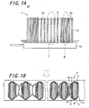
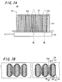
- Figs. 7A and 7B each show a schematic diagram of one example of such a fuel cell stack.
- Fig. 7A is a side view schematically showing a conventional fuel cell stack 51
- Fig. 7B is a partly enlarged plan view of the conventional fuel cell stack 51.
- the left-hand part shows an enlarged plan view of Section VII of Fig. 7A
- the right-hand part shows an enlarged plan view of Section VIII of Fig. 7A
- a plurality of fuel cells are arranged side by side in such a manner as to provide uniformity in the interval between the adjacent fuel cells.
- the fuel cells constituting the fuel cell stack produce heat in accompaniment with generation of electric power.
- the heat produced with the electric power generation in the fuel cells is dissipated through a gap between the adjacent fuel cells and so forth.
- the fuel cells liberate heat energy due to Joule heat and reaction heat of their own in the course of electric power generation.
- the heat energy cannot be dissipated readily and thus the temperature tends to become higher.
- the midportion of the fuel cell stack in the direction of arrangement of the fuel cells is high in temperature, whereas the end part of the fuel cell stack in the direction of arrangement of the fuel cells is low in temperature. Therefore, the fuel cell stack poses nonuniformity of temperature distribution (hill-form temperature distribution) in the direction of arrangement of the fuel cells, which may cause a decrease in power generation efficiency.
- JP 06251790 A discloses a fuel cell where plural unit cells and separator plates are laminated alternately. A thickness of the separator plate in the central part of the stack is made thicker than in the other part.
- EP 1686642 A1 discloses a fuel cell stack in which electricity generators and separators are stacked.
- the stack comprises heat releasing means. Those in the center of the stack are thicker than other ones.
- the invention provides a fuel cell stack comprising:
- the interval between adjacent fuel cells arranged in the midportion of the fuel cell stack in the direction of arrangement of the fuel cells (hereafter occasionally abbreviated as “midportion") is set to be wider than the interval between adjacent fuel cells arranged at either end of the fuel cell stack in the direction of arrangement of the fuel cells (hereafter occasionally abbreviated as "end”).
- the fuel cells in the middle of the stack are thinner than those at the ends of the stade. By doing so, the temperature distribution in the direction of placement of the fuel cell stack can be made uniform (or made as nearly uniform as possible).
- the fuel cells liberate heat energy due to Joule heat and reaction heat of their own in the course of electric power generation.
- the heat energy cannot be dissipated readily and thus the temperature becomes higher.
- the temperature distribution becomes uneven; that is, the midportion of the fuel cell stack is in a high-temperature state, whereas either end of the fuel cell stack is in a low-temperature state. This may cause a decrease in power generating efficiency.
- the interval between a plurality of the fuel cells arranged in the midportion of the fuel cell stack in the direction of arrangement of the fuel cells is set to be wider than the interval between a plurality of the fuel cells arranged at either end of the fuel cell stack in the direction of arrangement of the fuel cells. This helps facilitate heat-energy dissipation in a plurality of the fuel cells arranged in the midportion, wherefore the temperature of a plurality of the fuel cells arranged in the midportion can be lowered.
- the interval between the adjacent fuel cells is set to be narrower than the interval between the adjacent ones of a plurality of the fuel cells arranged in the midportion.
- the plurality of the fuel cells arranged at either end are so arranged that the interval between the adjacent fuel cells becomes narrower gradually with approach toward a corresponding extremity in the direction of arrangement of the fuel cells.
- the plurality of the fuel cells arranged at either end are so arranged that the interval between the adjacent fuel cells becomes narrower gradually from the midportion to the corresponding extremity in the direction of arrangement of the fuel cells.
- the interval between the adjacent fuel cells varies, for example, increases (or decreases) rapidly, it is possible to suppress application of an excessive stress to a plurality of the fuel cells arranged at either end, and thereby enhance the reliability of the fuel cell stack.
- the plurality of the fuel cells arranged in the midportion in the direction of arrangement of the fuel cells are made smaller in thickness than the plurality of the fuel cells arranged at either end in the direction of arrangement of the fuel cells.
- the interval between the center of one fuel cell and the center of the other fuel cell (for example, the interval between the fuel gas paths, respectively, of the adjacent fuel cells) is set at a fixed value, and the fuel cells arranged in the midportion in the direction of arrangement of the fuel cells are made smaller in thickness than the fuel cells arranged at either end in the arrangement direction.
- the interval between a plurality of the fuel cells arranged in the midportion is wider than the interval between a plurality of the fuel cells arranged at either end, wherefore the temperature distribution in the direction of placement of the fuel cell stack can be made uniform (or made as nearly uniform as possible).
- the fuel cell is a hollow flat plate-shaped fuel cell and is disposed uprightly in a manifold for supplying a fuel gas to the fuel cell.
- the fuel cell is formed in the shape of a hollow flat plate and is disposed uprightly in the manifold for supplying a fuel gas to the fuel cell.
- the fuel cell stack in which are arranged the fuel cells side by side at varying intervals, as well as to supply a fuel gas to the fuel cells.
- the fuel cell in the shape of a hollow flat plate, it is possible to manufacture with ease the fuel cell stack that is low in electrical resistance and is thus capable of exhibiting high power generation capability, in which are arranged the fuel cells side by side at varying intervals.
- the invention provides a fuel cell apparatus comprising:
- the fuel cell stack inside the housing are accommodated the fuel cell stack and the oxygen-containing gas supply means for feeding an oxygen-containing gas to the fuel cell.
- an oxygen-containing gas is supplied from the side face of the fuel cell stack along the direction of arrangement of the fuel cells, and the thereby supplied oxygen-containing gas flows between the fuel cells.
- the oxygen-containing gas traveling between the fuel cells it is possible to decrease the temperature of the fuel cells.
- a wider interval is secured between a plurality of the fuel cells arranged in the midportion in the direction of arrangement of the fuel cells. This makes it possible to increase the amount of flow of the oxygen-containing gas flowing between a plurality of the fuel cells arranged in the midportion, and thereby enhance the effect of cooling down a plurality of the fuel cells arranged in the midportion.
- the interval between the adjacent ones is set to be narrower than the interval between a plurality of the fuel cells arranged in the midportion. Therefore, the amount of flow of the oxygen-containing gas flowing between a plurality of the fuel cells arranged at either end is smaller than the amount of flow of the oxygen-containing gas flowing between a plurality of the fuel cells arranged in the midportion. As a result, the cooling effect exerted on a plurality of the fuel cells arranged at either end is lower than the cooling effect exerted on a plurality of the fuel cells arranged in the midportion.
- the temperature distribution of the fuel cell stack can be made uniform (or made as nearly uniform as possible) even further and a decrease in power generation efficiency in the fuel cell stack can be suppressed. Accordingly, it is possible to obtain a fuel cell apparatus that succeeds in providing enhanced power generation efficiency.
- the fuel cells are electrically connected in series to each other via a power collecting member, and that the power collecting member is so shaped as to permit of circulation of the oxygen-containing gas.
- the power collecting member is so shaped as to permit of circulation of the oxygen-containing gas. This makes it possible to allow the oxygen-containing gas supplied from the side face of the fuel cell stack along the direction of arrangement of the fuel cells to flow between the adjacent fuel cells readily. In this way, the temperature distribution of the fuel cell stack can be uniformized (or made as nearly uniform as possible), wherefore it is possible to produce a fuel cell apparatus that succeeds in providing enhanced power generation efficiency.
- the oxygen-containing gas supply means is disposed so that the oxygen-containing gas is allowed to flow within the oxygen-containing gas supply means in a direction from top to bottom along the fuel cell.
- the oxygen-containing gas supply means is disposed so that the oxygen-containing gas is allowed to flow within the oxygen-containing gas supply means in the direction from top to bottom along the fuel cell. In this way, the temperature distribution in the direction of from top to bottom of the fuel cell can be uniformized (or made as nearly uniform as possible).
- the fuel cells constituting the fuel cell stack show a tendency that the upper part thereof is in a high-temperature state, whereas the lower part thereof is in a low-temperature state.
- the oxygen-containing gas is allowed to flow within the oxygen-containing gas supply means in the direction from top to bottom along the fuel cell, the oxygen-containing gas is heated up while flowing through the fuel cell in the direction from top to bottom thereof.
- the oxygen-containing gas in a heated state flows toward the lower part of the fuel cell, wherefore the temperature of the lower part of the fuel cell can be raised.
- the temperature distribution in the direction of from top to bottom of the fuel cell can be uniformized. This makes it possible to enhance the power generation efficiency in the fuel cell, and thereby produce a fuel cell apparatus that succeeds in providing enhanced power generation efficiency.
- a reformer for generating a fuel gas which is supplied to the fuel cell is provided above the fuel cell stack.
- the reformer for generating a fuel gas which is supplied to the fuel cell is provided above the fuel cell stack.
- the reformer is heated up by the heat from the fuel cell stack.
- the temperature distribution in the direction of arrangement of the fuel cells can be uniformized (or made as nearly uniform as possible). Therefore, the temperature of the reformer can be raised more efficiently and a reforming reaction can thus be developed efficiently in the reformer. This makes it possible to produce a fuel cell apparatus whose power generation efficiency is enhanced even further.
- the interval between a plurality of the fuel cells arranged in the midportion in the direction of arrangement of the fuel cells is set to be wider than the interval between a plurality of the fuel cells arranged at either end in the direction of arrangement of the fuel cells. In this way, the temperature distribution of the fuel cell stack in the direction of arrangement of the fuel cells can be uniformized, wherefore a decrease in power generation efficiency can be suppressed.
- Figs. 1A and 1B show a fuel cell stack apparatus 10 having a fuel cell stack 1.
- Fig. 1A is a side view schematically showing the fuel cell stack apparatus 10
- Fig. 1B is a partly enlarged plan view of the fuel cell stack apparatus 10 depicted in Fig. 1A .
- the left-hand part shows an enlarged plan view of Section I of Fig. 1A
- the right-hand part shows an enlarged plan view of Section II of Fig. 1A .
- like members are identified by the same reference numbers, and this holds true for what follows.
- an arrow shown by a dotted line in Fig. 1B indicates a direction in which an oxygen-containing gas flows.
- the fuel cell stack apparatus 10 of the invention includes the fuel cell stack 1 and a manifold 12.
- the fuel cell stack 1 is constructed by electrically connecting a plurality of fuel cells 2 in series with each other.
- Each of the fuel cells 2 is formed by laminating a fuel-side electrode layer 5, a solid-state electrolytic layer 6, and an air-side electrode layer 4 one after another on a support substrate 8.
- the fuel cell stack 1 is fixedly attached to the manifold 12, with the fuel cells 2 arranged in an array.
- a power collecting member 3a is set between the adjacent fuel cells 2
- an end-side power collecting member 3b is set between the adjacent fuel cells 2 located on either side of the fuel cell stack in the direction of arrangement of the fuel cells 2.
- the fuel cell stack apparatus 10 is provided with an alloy-made holding member 13 which is uprightly fixed to the manifold 12 for supplying a fuel gas to the fuel cells 2 so as to retain the fuel cell stack 1 via the end-side power collecting member 3b from either side of the fuel cell stack in the direction of arrangement of the fuel cells 2.
- one ends (lower ends) of, respectively, the fuel cell 2 and the holding member 13 are buried in and bonded to the manifold 12 by means of, for example, a glass sealing material (not shown in the figure) having high heat resistance.
- the fuel cell 2 is formed in the shape of a hollow flat plate.
- the fuel cell 2 is constructed of a columnar conductive support substrate 8 having a pair of opposite flat surfaces, on one of the flat surfaces of which are successively laminated the fuel-side electrode layer 5, the solid-state electrolytic layer 6, and the air-side electrode layer 4, and on the other flat surface of which is disposed an interconnector 7.
- a fuel gas flow channel 9 is disposed in the conductive support substrate 8 interiorly thereof for permitting of circulation of a reaction gas (fuel gas).
- a reaction gas fuel gas
- such a configuration is defined as "hollow flat-plate shape”.
- a P-type semiconductor 11 may be disposed on the outer surface (top surface) of the interconnector 7.
- the P-type semiconductor 11 By connecting the power collecting member 3a to the interconnector 7 via the P-type semiconductor 11, it is possible to establish ohmic contact between them. In this case, the degree of potential drop is lessened, wherefore a deterioration in electricity collecting capability can be avoided effectively. Note that each of the components constituting the fuel cell 2 will hereafter be described in detail.
- the conductive support substrate 8 may be so designed as to serve also as the fuel-side electrode layer 5.
- the fuel cell 2 can be constructed by laminating, on the surface of such a conductive support substrate, the solid-state electrolytic layer 6 and the air-side electrode layer 4 successively.
- the fuel cell stack 1 is characterized in that the interval between a plurality of the fuel cells 2 arranged in the midportion of the fuel cell stack in the direction of arrangement of the fuel cells 2 is set to be wider than the interval between a plurality of the fuel cells 2 arranged at either end of the fuel cell stack in the direction of arrangement of the fuel cells 2.
- a plurality of the fuel cells 2 arranged in the midportion of the fuel cell stack in the direction of arrangement of the fuel cells 2 refer to the fuel cells arranged centrally in the direction of arrangement of a plurality of the fuel cells 2 and the fuel cells arranged in the vicinity thereof.
- the number of the fuel cells concerned may be determined as appropriate.
- the number of the fuel cells concerned may also be determined as appropriate in consideration of the length of the fuel cell stack in the direction of arrangement of the fuel cells 2, the size of the fuel cell 2, and so forth.
- the fuel cells 2 arranged within a region constituting about a third of the length of the fuel cell stack located centrally with respect to the midportion in the direction of arrangement of the fuel cells 2 can be defined as "a plurality of the fuel cells 2 arranged in the midportion”
- the fuel cells 2 arranged within a region constituting about a third of the length of the fuel cell stack lying between either end and the midportion in the direction of arrangement of the fuel cells 2 can be defined as "a plurality of the fuel cells 2 arranged at either end”.
- a group of a plurality of the fuel cells 2 arranged in the midportion and a group of a plurality of the fuel cells 2 arranged at either end can be arranged the fuel cell 2 which is independent of the two groups.
- the fuel cell stack constructed by arranging a plurality of the fuel cells produces heat in accompaniment with generation of electric power in the fuel cells.
- the fuel cell stack constructed by arranging a plurality of the fuel cells incurs uneven temperature distribution in the direction of arrangement of the fuel cells (the midportion is in a high-temperature state, whereas either end is in a low-temperature state). This may cause a deterioration in the power generation capability of the fuel cell stack.
- the interval between a plurality of the fuel cells 2 arranged in the midportion of the fuel cell stack in the direction of arrangement of the fuel cells 2 is set to be wider than the interval between a plurality of the fuel cells 2 arranged at either end of the fuel cell stack in the direction of arrangement of the fuel cells 2. This helps facilitate heat-energy dissipation in the fuel cells 2 arranged in the midportion, wherefore the temperature of the midportion of the fuel cell stack 1 can be lowered.
- the interval between the adjacent fuel cells 2 is set to be narrower than the interval between a plurality of the fuel cells 2 arranged in the midportion. Therefore, as compared with the case for the midportion, the heat energy cannot be dissipated readily, with the result that a drop in the temperature of the end-side part of the fuel cell stack 1 is suppressed or the temperature of the end-side part is caused to rise.
- the fuel cell stack 1 assumes a gently-curved temperature distribution shape. Moreover, by making adjustment to the interval between the adjacent fuel cells 2 properly, it is possible to make the temperature distribution of the fuel cell stack 1 as nearly uniform as possible.
- the fuel cell stack 1 of the invention can be implemented as the fuel cell stack 1 that offers improved power generation capability.
- the interval between a plurality of the fuel cells 2 arranged at either end be narrower than the interval between a plurality of the fuel cells 2 arranged in the midportion. That is, in a plurality of the fuel cells 2 arranged in the midportion or at either end, the adjacent fuel cells 2 may be arranged at a uniform interval. Further, a plurality of the fuel cells 2 arranged at either end may be so arranged that the interval between the adjacent fuel cells 2 becomes wider gradually with approach toward the corresponding extremity.
- the support substrate 8 is required to be gas-permeable for allowing a fuel gas to permeate to the fuel-side electrode layer 5, and is also required to be electrically conductive for collecting electricity through the interconnector 7. It is thus necessary to adopt a material that satisfies such requirements for the support substrate 8. For example, electrically conductive ceramic or cermet may be used.
- the power collecting member 3a and the end-side power collecting member 3b may be constructed of a component made of an elastic metal or alloy, or a component formed by performing a predetermined surface treatment on a felt made of metallic fiber or alloy fiber.
- the power collecting member 3a of the invention should preferably be constructed of a component made of an elastic alloy. This makes it possible to establish electrical connection of the fuel cells 2. Note that, for example, it is possible to place the power collecting member 3a whose size is changed in accordance with the interval between the fuel cells 2. The shape of the power collecting member 3a will be described later on.
- the air-side electrode layer 4 may be formed of electrically conductive ceramic made of a so-called ABO 3 type perovskite oxide.
- the air-side electrode layer 4 needs to be designed to exhibit gas permeability and should preferably have an open porosity of greater than or equal to 20%, and more particularly an open porosity falling within a range from 30 to 50%.
- the fuel-side electrode layer 5 may be formed of porous conductive ceramic, for example, ZrO 2 solid solution containing a rare earth element (called stabilized zirconia), and Ni and/or NiO.
- porous conductive ceramic for example, ZrO 2 solid solution containing a rare earth element (called stabilized zirconia), and Ni and/or NiO.
- the solid-state electrolytic layer 6 is required to function as an electrolyte for interfacing electrons between the electrodes, as well as to have a gas barrier property for prevention of the leakage of a fuel gas and an oxygen-containing gas.
- the solid-state electrolytic layer 6 is thus formed of ZrO 2 solid solution containing a rare earth element in an amount of 3 to 15 mol%. Note that any other material may be used to form the solid-state electrolytic layer 6 so long as it has the aforestated characteristics.
- the interconnector 7 which may be formed of electrically conductive ceramic, is required to exhibit resistance to reduction and resistance to oxidation as well because it is brought into contact with a fuel gas (hydrogen gas) and an oxygen-containing gas (air or the like). Therefore, a lanthanum chromite-based perovskite-type oxide (LaCrO 3 -based oxide) is desirable for use.
- the interconnector 7 In order to prevent the leakage of a fuel gas which passes through the fuel gas flow channel 9 formed in the support substrate 8 and the leakage of an oxygen-containing gas which flows outside of the support substrate 8 as well, the interconnector 7 needs to have a dense. It is thus preferable that the interconnector 7 has a relative density of 93% or above, and more particularly 95% or above.
- the support substrate 8 may be designed as a hollow flat plate-shaped support substrate.
- the support substrate 8 is formed in the shape of a slim plate-like piece that extends in an upstanding direction and has opposite flat surfaces and opposite semicircular side faces.
- a plurality (six pieces, in Fig. 1B ) of fuel gas flow channels 9 so as to pass through the interior of the support substrate 8 in the upstanding direction.
- Each of the fuel cells 2 is bonded to the upper wall (top) of the manifold 12 for supplying a fuel gas by means of, for example, a glass sealing material 12 having high heat resistance.
- the fuel gas flow channel 9 of the fuel cell 2 is communicated with a fuel gas chamber (not shown in the figure).
- the support substrate 8 is produced by co-firing with at least one of the fuel-side electrode layer 5 and the solid-state electrolytic layer 6, it is desirable to form the support substrate 8 with use of an iron-family metal component and a specific rare earth oxide.
- the conductive support substrate 8 should preferably have an open porosity of greater than or equal to 30%, and more particularly an open porosity falling within a range from 35 to 50%. It is also preferable that the electrical conductivity of the conductive support substrate 8 is greater than or equal to 300S/cm, and more particularly greater than or equal to 440S/cm.
- a layer made of a transition metal perovskite-type oxide may be taken up.
- P-type semiconductor layer 6 ranges in thickness from 30 to 100 ⁇ m.
- the fuel cell 2 constituting the fuel cell stack 1 is illustrated as a hollow flat plate-shaped fuel cell, and the fuel cell stack 1 is illustrated as being composed of the fuel cells 2 of the same thickness (having the same thickness in the arrangement direction).
- the fuel cell stack 1 is illustrated as being composed of the fuel cells 2 of the same thickness (having the same thickness in the arrangement direction).
- the fuel cells 2 may vary in thickness (have different thicknesses in the arrangement direction).
- the interval between the adjacent fuel cells arranged in the midportion may be determined as appropriate in consideration of the shape of the fuel cell, the number of the fuel cells, and so forth.
- the interval between the adjacent fuel cells arranged in the midportion may be set at 3 mm, and the interval between the adjacent fuel cells arranged at either end may be set at 2 mm.
- the interval between the fuel cells may be defined as "the interval between the surfaces of the adjacent fuel cells”.
- Figs. 2A and 2B show an example of a fuel cell stack apparatus 14 in which a plurality of the fuel cells 2 arranged at either end are so arranged that the interval between the adjacent fuel cells 2 becomes narrower gradually with approach toward the corresponding extremity in the direction of arrangement of the fuel cells 2.
- Fig. 2A is a side view schematically showing the fuel cell stack apparatus 14
- Fig. 2B is a partly enlarged plan view of the fuel cell stack apparatus 14 depicted in Fig. 2A .
- the left-hand part shows an enlarged plan view of Section III of Fig. 2A
- the right-hand part shows an enlarged plan view of Section IV of Fig. 2A .
- a fuel cell stack 15 thereby constructed, a plurality of the fuel cells 2 arranged at either end are so arranged that the interval between the adjacent fuel cells 2 becomes narrower gradually from the midportion to the corresponding extremity in the direction of arrangement of the fuel cells 2.
- the temperature distribution of the fuel cell stack 15 can be made as nearly uniform as possible.
- a plurality of the fuel cells 2 arranged at either end are so arranged that the interval between the adjacent fuel cells 2 becomes narrower gradually with approach toward the corresponding extremity in the arrangement direction.
- the interval between the adjacent fuel cells 2 varies, for example, increases (or decreases) suddenly, it is possible to suppress application of an excessive stress to the fuel cells 2 and the power collecting member 3a, and thereby enhance the reliability of the fuel cell stack 14.
- the fuel cells 2 may be so arranged that the interval between the adjacent fuel cells 2 becomes narrower gradually from the midportion to either end in the direction of arrangement of the fuel cells 2.
- Fig. 2 there is shown such a fuel cell stack apparatus 14 in which the temperature distribution of the fuel cell stack 15 can be made as nearly uniform as possible even further.
- Figs. 3A and 3B show an example of a fuel cell stack apparatus 16 in which a plurality of the fuel cells 2 arranged in the midportion are made smaller in thickness (thickness in the arrangement direction) than a plurality of the fuel cells 2 arranged at either end.
- Fig. 3A is a side view schematically showing the fuel cell stack apparatus 16
- Fig. 3B is a partly enlarged plan view of the fuel cell stack apparatus 16 depicted in Fig. 3A .
- the left-hand part shows an enlarged plan view of Section V of Fig. 3A
- the right-hand part shows an enlarged plan view of Section VI of Fig. 3A .
- the interval between the adjacent fuel cells (for example, the interval between the center of one fuel cell and the center of the other fuel cell in a plan view thereof) is set at a predetermined value, and a plurality of the fuel cells 2 arranged in the midportion are made smaller in thickness than a plurality of the fuel cells 2 arranged at either end. In this way, the interval between the adjacent ones of a plurality of the fuel cells 2 arranged in the midportion is wider than the interval between the adjacent ones of a plurality of the fuel cells 2 arranged at either end.
- the interval between the adjacent fuel cells 2 (the interval between the center of one fuel cell 2 and the center of the fuel cell 2 placed adjacent thereto) is set at 5 mm. Then, the thickness of each of a plurality of the fuel cells 2 arranged in the midportion is set at 2 mm and the thickness of each of a plurality of the fuel cells 2 arranged at either end is set at 3 mm. In this way, the interval between a plurality of the fuel cells 2 arranged in the midportion is wider than the interval between a plurality of the fuel cells 2 arranged at either end.
- the interval between the adjacent fuel cells 2 and the thickness of the fuel cell 2 may be determined as appropriate in consideration of the size of the fuel cell, the size of the fuel cell stack, and so forth. For example, in a plurality of the fuel cells arranged at either end, the thickness of the fuel cell 2 may be charged on an as needed basis so long as it is smaller than the thickness of each of a plurality of the fuel cells 2 arranged in the midportion.
- the fuel cell apparatus of the invention can be provided.
- Fig. 4 is an external perspective view showing one example of a fuel cell apparatus according to the invention.
- a fuel cell apparatus 18 is constructed by placing, inside a housing 19 having the shape of a rectangular prism, the aforestated fuel cell stack and oxygen-containing gas supply means 20 for feeding an oxygen-containing gas to the fuel cell 2.
- the fuel cell stack for use the fuel cell stack 1 shown in Figs. 1A and 1B is exemplified.
- a reformer 21 for generating a hydrogen gas by reforming a fuel such as a natural gas and kerosene.
- a fuel such as a natural gas and kerosene.
- Fig. 4 there is shown a state where part of the housing 19 (front face and rear face) has been removed and the fuel cell stack apparatus 10 placed inside the housing 19 has been pulled out backward.
- the fuel cell stack apparatus 10 can be slidingly accommodated inside the housing 19.
- Fig. 5 is a sectional view of the fuel cell apparatus 18 taken along the section line X-X shown in Fig. 4 .
- the housing 19 constituting the fuel 18 takes on a dual structure having an inner wall 22 and an outer wall 23.
- the outer wall 23 constitutes the outer frame of the housing 19, whereas the inner wall 22 constitutes a power generating chamber 24 for housing the fuel cell stack 1 (the fuel cell stack apparatus 10).
- a region between the inner wall 22 and the outer wall 23 serves as a flow channel for a reaction gas which is introduced into the fuel cell 2.
- a reaction gas which is introduced into the fuel cell 2.
- an oxygen-containing gas and so forth to be introduced into the fuel cell 2 flow through the flow channel.
- an oxygen-containing gas introducing member 20 acting as the oxygen-containing gas supply means which extends from the top surface of the inner wall 22 to the side-face part of the fuel cell stack 1, is adapted to the width of the fuel cell stack 1 in the arrangement direction, and communicates with the flow channel constituted by the inner wall 22 and the outer wall 23, for introducing an oxygen-containing gas into the fuel cell 2.
- an outlet port 25 for introducing an oxygen-containing gas into the fuel cell 2.
- the oxygen-containing gas introducing member 20 is so designed that a pair of plate-like members arranged side by side at a predetermined spacing constitutes an oxygen-containing gas introducing flow channel and that its lower end is bonded to a bottom member. Moreover, while, in Fig. 5 , the oxygen-containing gas introducing member 20 is so placed as to be located between the two fuel cell stacks 1 (fuel cell stack apparatuses 10) juxtaposed to each other within the housing 19, depending upon the number of the fuel cell stacks 1 to be housed, for example, the oxygen-containing gas introducing member 20 may be so disposed as to sandwich the fuel cell stacks 1 from their side faces.
- a temperature sensor 26 having a temperature measuring portion 27 is inserted into the oxygen-containing gas introducing member 20 from the top-surface side of the housing 2. This makes it possible to measure the temperature of the fuel cell stack 1 (the fuel cell 2).
- a suitable heat insulating material 28 is placed inside the housing 19 . Note that a plurality of the temperature sensors 26 may be arranged for use. In this case, they should preferably be arranged in the midportion and the end-side part of the fuel cell stack, respectively.
- a fuel gas is supplied from the manifold 12 to the fuel cell 2 and an oxygen-containing gas is supplied to the fuel cell 2 as well. With use of these gases, electric power is generated.
- the supply of an oxygen-containing gas is effected by the oxygen-containing gas introducing member 20 to the fuel cell stack 1 through its side face along the direction of arrangement of the fuel cells 2, and the oxygen-containing gas flows between the fuel cells 2.
- an oxygen-containing gas is supplied in such a manner that it is introduced from a certain location in the direction of the side face of the fuel cells 2 (the fuel cell stack 1) and goes around the fuel cell stack 1 as a whole.
- a wider interval is secured between a plurality of the fuel cells 2 arranged in the midportion in the direction of arrangement of the fuel cells 2. This makes it possible to increase the amount of flow of the oxygen-containing gas flowing between a plurality of the fuel cells 2 arranged in the midportion, and thereby enhance the effect of cooling down a plurality of the fuel cells 2 arranged in the midportion (the effect of heat exchange).
- the interval of the adjacent fuel cells 2 is set to be narrower. Therefore, the amount of flow of the oxygen-containing gas flowing between a plurality of the fuel cells 2 arranged at either end is smaller than the amount of flow of the oxygen-containing gas flowing between a plurality of the fuel cells 2 arranged in the midportion. As a result, the cooling effect exerted on the fuel cells 2 arranged at either end is lower than that exerted on the fuel cells 2 arranged in the midportion.
- the temperature of a plurality of the fuel cells 2 arranged in the midportion in the direction of arrangement of the fuel cells 2 becomes even lower. This makes it possible to render the temperature distribution of the fuel cell stack 1 as nearly uniform as possible, and thereby suppress a decrease in power generation efficiency in the fuel cell stack 1.
- the oxygen-containing gas introducing member 20 shown in Fig. 5 is placed in such a manner that an oxygen-containing gas is allowed to flow within the oxygen-containing gas introducing member 20 in the direction from top to bottom along the fuel cell 2.
- the reformer 21 for supplying a fuel gas (reformed gas) to the fuel cell 2 (the manifold 12) is placed above the fuel cell stack 1.
- the fuel cells 2 constituting the fuel cell stack 1 show a tendency that the upper part thereof is in a high-temperature state, whereas the lower part thereof is in a low-temperature state.
- the oxygen-containing gas is allowed to flow within the oxygen-containing gas supply means 20 in the direction from top to bottom along the fuel cell 2, the oxygen-containing gas is heated up while flowing through the fuel cell 2 in the direction from top to bottom thereof.
- the oxygen-containing gas in a heated state is supplied, through the outlet port 25 formed on the lower-end side of the oxygen-containing gas introducing member 20, to the lower part of the fuel cell 20.
- the temperature of the lower part of the fuel cell 20 can be raised.
- the temperature distribution in the direction of from top to bottom (upstanding direction) of the fuel cell 20 can be uniformized, wherefore the power generation efficiency in the fuel cell 20 can be enhanced.
- the heat from the fuel cell stack 1 is transmitted to the reformer 21, whereupon the bottom surface of the reformer 21 is heated up.
- the reformer 21 is able to enhance a reforming reaction by exploiting the heat from the fuel cell stack 1 effectively.
- the temperature distribution in the direction of arrangement of the fuel cells 2 can be made as nearly uniform as possible, it follows that the reformer 21 can be heated, with its temperature kept more even. Accordingly, a reforming reaction in the reformer 21 can be conducted efficiently, wherefore the fuel cell apparatus 18 succeeds in providing enhanced power generation efficiency.
- Fig. 6 shows one example of the power collecting member 3a disposed between the adjacent fuel cells 2 in the fuel cell stack 1.
- the power collecting member 3a has, as basic elements, a first electrical conductor piece 30 which abuts against the flat surface of one of the adjacent fuel cells 2, a second electrical conductor piece 31 which extends inclinedly from the end of one of the adjacent fuel cells 2 to the end of the other of the adjacent fuel cells 2, a third electrical conductor piece 32 which abuts against the flat surface of the other of the adjacent fuel cells 2, and a fourth electrical conductor piece 33 which extends inclinedly from the end of the other of the adjacent fuel cells 2 to the end of one of the adjacent fuel cells 2.
- the first to fourth electrical conductor pieces are each connected to respective following electrical conductor pieces at their ends in this order, and further, the electrical conductor pieces are repeatedly connected in this order. These connections constitute a unitary power collecting member 3a extending in an axial direction thereof.
- the end-side power collecting member 3b may be similar in configuration to the power collecting member 3a.
- the temperature distribution of the fuel cell stack 1 can be made as nearly uniform as possible, it is possible to suppress a decrease in power generation efficiency in the fuel cell stack 1. That is, there is obtained a fuel cell apparatus that succeeds in providing enhanced power generation efficiency.
- the description of the fuel cell stack of the invention deals with the case of using a hollow flat plate-shaped fuel cell as the fuel cell
- a plate-shaped or cylindrical-shaped fuel cell may be used instead.
- the interval between the fuel cells may be varied by making changes to the sizes of, respectively, the oxygen-side electrode layer, the fuel-side electrode layer, the separator, and so forth that constitute the fuel cell.
Description
- The present invention relates to a fuel cell stack constructed by arranging a plurality of fuel cells, as well as to a fuel cell apparatus constructed by housing the fuel cell stack into place.
- As the coming generation of energy, in recent years, there have been proposed various types of fuel cell apparatuses each constructed by placing, inside a housing, a fuel cell stack composed of an array of a plurality of fuel cells capable of obtaining electric power by exploiting a fuel gas and air (oxygen-containing gas) that are electrically connected in series to each other.
- In such a fuel cell apparatus, a hydrogen gas is used as a fuel gas for use in electric power generation. Electric power is generated through a predetermined electrode reaction induced by bringing the hydrogen gas into contact with a fuel-side electrode layer of the fuel cell and bringing the oxygen-containing gas into contact with an air-side electrode layer of fuel cell.
- In this connection, there have been proposed many fuel cell stacks each constructed by arranging a plurality of fuel cells (for example, refer to Japanese Unexamined Patent Publication
JP-A 2003-308857 -
Figs. 7A and 7B each show a schematic diagram of one example of such a fuel cell stack.Fig. 7A is a side view schematically showing a conventionalfuel cell stack 51, andFig. 7B is a partly enlarged plan view of the conventionalfuel cell stack 51. Note that, inFig. 7B , the left-hand part shows an enlarged plan view of Section VII ofFig. 7A , whereas the right-hand part shows an enlarged plan view of Section VIII ofFig. 7A . In thefuel cell stack 51 shown inFigs. 7A and 7B , a plurality of fuel cells are arranged side by side in such a manner as to provide uniformity in the interval between the adjacent fuel cells. - The fuel cells constituting the fuel cell stack produce heat in accompaniment with generation of electric power. The heat produced with the electric power generation in the fuel cells is dissipated through a gap between the adjacent fuel cells and so forth.
- However, in the fuel cell stack constructed by arranging a plurality of (especially, a multiplicity of) fuel cells, the fuel cells liberate heat energy due to Joule heat and reaction heat of their own in the course of electric power generation. In particular, in a plurality of fuel cells arranged centrally in the direction of arrangement of the fuel cells, due to the presence of a multiplicity of fuel cells arranged on both sides thereof, the heat energy cannot be dissipated readily and thus the temperature tends to become higher.
- On the other hand, in a plurality of fuel cells arranged at either end in the direction of arrangement of the fuel cells, since the number of the fuel cells arranged adjacent thereto is small, or since no fuel cell lies adjacent thereto, it follows that the heat energy can be dissipated readily. In consequence, the fuel cells arranged at either end in the direction of arrangement of the fuel cells are prone to undergo a decrease in temperature.
- That is, the midportion of the fuel cell stack in the direction of arrangement of the fuel cells is high in temperature, whereas the end part of the fuel cell stack in the direction of arrangement of the fuel cells is low in temperature. Therefore, the fuel cell stack poses nonuniformity of temperature distribution (hill-form temperature distribution) in the direction of arrangement of the fuel cells, which may cause a decrease in power generation efficiency.
-
JP 06251790 A -
EP 1686642 A1 discloses a fuel cell stack in which electricity generators and separators are stacked. The stack comprises heat releasing means. Those in the center of the stack are thicker than other ones. - It is the object of the invention to provide a fuel cell stack and a fuel cell apparatus with improved uniformity of the temperature distribution along the stack.
- This object is accomplished by the features of
claim 1. - The invention provides a fuel cell stack comprising:
- - an array of a plurality of fuel cells electrically connected in series to each other, the fuel cells each being formed by laminating a fuel-side electrode layer, a solid-state electrolytic layer, and an air-side electrode layer one after another on a support substrate,
- an interval between adjacent fuel cells arranged in a midportion of the fuel cell stack in a direction of arrangement of the fuel cells being wider than an interval between a plurality of the fuel cells arranged at either end of the fuel cell stack in the direction of arrangement of the fuel cells.
- According to such a fuel cell stack, the interval between adjacent fuel cells arranged in the midportion of the fuel cell stack in the direction of arrangement of the fuel cells (hereafter occasionally abbreviated as "midportion") is set to be wider than the interval between adjacent fuel cells arranged at either end of the fuel cell stack in the direction of arrangement of the fuel cells (hereafter occasionally abbreviated as "end"). The fuel cells in the middle of the stack are thinner than those at the ends of the stade. By doing so, the temperature distribution in the direction of placement of the fuel cell stack can be made uniform (or made as nearly uniform as possible).
- That is, in general, in a fuel cell stack constructed by arranging a plurality of fuel cells, the fuel cells liberate heat energy due to Joule heat and reaction heat of their own in the course of electric power generation. At this time, in the fuel cells arranged in the midportion, due to the presence of a multiplicity of fuel cells arranged on both sides thereof, the heat energy cannot be dissipated readily and thus the temperature becomes higher.
- On the other hand, in the fuel cells arranged at either end in the direction of arrangement of the fuel cells, since the number of the fuel cells arranged adjacent thereto is small, or since no fuel cell lies adjacent thereto, it follows that the heat energy can be dissipated readily and thus a decrease in temperature tends to occur.
- As a consequence, the temperature distribution becomes uneven; that is, the midportion of the fuel cell stack is in a high-temperature state, whereas either end of the fuel cell stack is in a low-temperature state. This may cause a decrease in power generating efficiency.
- Therefore, in the fuel cell stack of the invention, the interval between a plurality of the fuel cells arranged in the midportion of the fuel cell stack in the direction of arrangement of the fuel cells is set to be wider than the interval between a plurality of the fuel cells arranged at either end of the fuel cell stack in the direction of arrangement of the fuel cells. This helps facilitate heat-energy dissipation in a plurality of the fuel cells arranged in the midportion, wherefore the temperature of a plurality of the fuel cells arranged in the midportion can be lowered. Moreover, in a plurality of the fuel cells arranged at either end of the fuel cell stack in the direction of arrangement of the fuel cells, the interval between the adjacent fuel cells is set to be narrower than the interval between the adjacent ones of a plurality of the fuel cells arranged in the midportion. This leads to difficulty in heat dissipation, wherefore a decrease in temperature can be suppressed (or temperature rise can be induced). In this way, the temperature distribution of the fuel cell stack can be made uniform (or made as nearly uniform as possible) and a decrease of power generation efficiency in the fuel cell stack can thus be suppressed.
- Moreover, in the fuel cell stack of the invention, it is preferable that the plurality of the fuel cells arranged at either end are so arranged that the interval between the adjacent fuel cells becomes narrower gradually with approach toward a corresponding extremity in the direction of arrangement of the fuel cells.
- According to such a fuel cell stack, since the plurality of the fuel cells arranged at either end are so arranged that the interval between the adjacent fuel cells becomes narrower gradually with approach toward the corresponding extremity in the direction of arrangement of the fuel cells, it follows that the temperature distribution of the fuel cell stack can be uniformized (or made as nearly uniform as possible) and a decrease of power generation efficiency in the fuel cell stack can thus be suppressed.
- Moreover, the plurality of the fuel cells arranged at either end are so arranged that the interval between the adjacent fuel cells becomes narrower gradually from the midportion to the corresponding extremity in the direction of arrangement of the fuel cells. In this case, since the interval between the adjacent fuel cells varies, for example, increases (or decreases) rapidly, it is possible to suppress application of an excessive stress to a plurality of the fuel cells arranged at either end, and thereby enhance the reliability of the fuel cell stack.
- In the fuel cell stack of the invention, the plurality of the fuel cells arranged in the midportion in the direction of arrangement of the fuel cells are made smaller in thickness than the plurality of the fuel cells arranged at either end in the direction of arrangement of the fuel cells.
- According to such a fuel cell stack of the invention, in constructing the fuel cell stack by arranging a plurality of fuel cells side by side, not only it is possible to use fuel cells of varying thickness.
- In this case, in the adjacent fuel cells, the interval between the center of one fuel cell and the center of the other fuel cell (for example, the interval between the fuel gas paths, respectively, of the adjacent fuel cells) is set at a fixed value, and the fuel cells arranged in the midportion in the direction of arrangement of the fuel cells are made smaller in thickness than the fuel cells arranged at either end in the arrangement direction. In this way, the interval between a plurality of the fuel cells arranged in the midportion is wider than the interval between a plurality of the fuel cells arranged at either end, wherefore the temperature distribution in the direction of placement of the fuel cell stack can be made uniform (or made as nearly uniform as possible).
- Moreover, in the fuel cell stack of the invention, it is preferable that the fuel cell is a hollow flat plate-shaped fuel cell and is disposed uprightly in a manifold for supplying a fuel gas to the fuel cell.
- According to such a fuel cell stack, the fuel cell is formed in the shape of a hollow flat plate and is disposed uprightly in the manifold for supplying a fuel gas to the fuel cell. In this case, it is possible to manufacture with ease the fuel cell stack in which are arranged the fuel cells side by side at varying intervals, as well as to supply a fuel gas to the fuel cells.
- Moreover, by forming the fuel cell in the shape of a hollow flat plate, it is possible to manufacture with ease the fuel cell stack that is low in electrical resistance and is thus capable of exhibiting high power generation capability, in which are arranged the fuel cells side by side at varying intervals.
- The invention provides a fuel cell apparatus comprising:
- any of the fuel cell stacks as set forth hereinabove;
- oxygen-containing gas supply means for feeding an oxygen-containing gas to the fuel cell; and
- a housing for accommodating therein the fuel cell stack and the oxygen-containing gas supply means,
- an oxygen-containing gas being supplied from a side face of the fuel cell stack along the direction of arrangement of the fuel cells, and the oxygen-containing gas flowing between the fuel cells.
- According to such a fuel cell apparatus, inside the housing are accommodated the fuel cell stack and the oxygen-containing gas supply means for feeding an oxygen-containing gas to the fuel cell. In this construction, an oxygen-containing gas is supplied from the side face of the fuel cell stack along the direction of arrangement of the fuel cells, and the thereby supplied oxygen-containing gas flows between the fuel cells. By virtue of the oxygen-containing gas traveling between the fuel cells, it is possible to decrease the temperature of the fuel cells.
- In this case, in the fuel cell stack constructed by arranging a plurality of the fuel cells, a wider interval is secured between a plurality of the fuel cells arranged in the midportion in the direction of arrangement of the fuel cells. This makes it possible to increase the amount of flow of the oxygen-containing gas flowing between a plurality of the fuel cells arranged in the midportion, and thereby enhance the effect of cooling down a plurality of the fuel cells arranged in the midportion.
- On the other hand, in the plurality of the fuel cells arranged at either end in the direction of arrangement of the fuel cells, the interval between the adjacent ones is set to be narrower than the interval between a plurality of the fuel cells arranged in the midportion. Therefore, the amount of flow of the oxygen-containing gas flowing between a plurality of the fuel cells arranged at either end is smaller than the amount of flow of the oxygen-containing gas flowing between a plurality of the fuel cells arranged in the midportion. As a result, the cooling effect exerted on a plurality of the fuel cells arranged at either end is lower than the cooling effect exerted on a plurality of the fuel cells arranged in the midportion.
- In this way, the temperature distribution of the fuel cell stack can be made uniform (or made as nearly uniform as possible) even further and a decrease in power generation efficiency in the fuel cell stack can be suppressed. Accordingly, it is possible to obtain a fuel cell apparatus that succeeds in providing enhanced power generation efficiency.
- Moreover, in the fuel cell apparatus of the invention, it is preferable that the fuel cells are electrically connected in series to each other via a power collecting member, and that the power collecting member is so shaped as to permit of circulation of the oxygen-containing gas.
- According to such a fuel cell apparatus, since the fuel cells are electrically connected in series to each other via the power collecting member, it is possible to collect electricity generated by the fuel cells with high efficiency.
- Moreover, the power collecting member is so shaped as to permit of circulation of the oxygen-containing gas. This makes it possible to allow the oxygen-containing gas supplied from the side face of the fuel cell stack along the direction of arrangement of the fuel cells to flow between the adjacent fuel cells readily. In this way, the temperature distribution of the fuel cell stack can be uniformized (or made as nearly uniform as possible), wherefore it is possible to produce a fuel cell apparatus that succeeds in providing enhanced power generation efficiency.
- Moreover, in the fuel cell apparatus of the invention, it is preferable that the oxygen-containing gas supply means is disposed so that the oxygen-containing gas is allowed to flow within the oxygen-containing gas supply means in a direction from top to bottom along the fuel cell.
- According to such a fuel cell apparatus, the oxygen-containing gas supply means is disposed so that the oxygen-containing gas is allowed to flow within the oxygen-containing gas supply means in the direction from top to bottom along the fuel cell. In this way, the temperature distribution in the direction of from top to bottom of the fuel cell can be uniformized (or made as nearly uniform as possible).
- Note that the fuel cells constituting the fuel cell stack show a tendency that the upper part thereof is in a high-temperature state, whereas the lower part thereof is in a low-temperature state.
- Therefore, as the oxygen-containing gas is allowed to flow within the oxygen-containing gas supply means in the direction from top to bottom along the fuel cell, the oxygen-containing gas is heated up while flowing through the fuel cell in the direction from top to bottom thereof.
- Then, the oxygen-containing gas in a heated state flows toward the lower part of the fuel cell, wherefore the temperature of the lower part of the fuel cell can be raised.
- In this way, the temperature distribution in the direction of from top to bottom of the fuel cell can be uniformized. This makes it possible to enhance the power generation efficiency in the fuel cell, and thereby produce a fuel cell apparatus that succeeds in providing enhanced power generation efficiency.
- Moreover, in the fuel cell apparatus of the invention, it is preferable that a reformer for generating a fuel gas which is supplied to the fuel cell is provided above the fuel cell stack.
- According to such a fuel cell apparatus, the reformer for generating a fuel gas which is supplied to the fuel cell is provided above the fuel cell stack. In this case, the reformer is heated up by the heat from the fuel cell stack.
- Note that, in the fuel cell stack of the invention, the temperature distribution in the direction of arrangement of the fuel cells can be uniformized (or made as nearly uniform as possible). Therefore, the temperature of the reformer can be raised more efficiently and a reforming reaction can thus be developed efficiently in the reformer. This makes it possible to produce a fuel cell apparatus whose power generation efficiency is enhanced even further.
- In the fuel cell stack of the invention, the interval between a plurality of the fuel cells arranged in the midportion in the direction of arrangement of the fuel cells is set to be wider than the interval between a plurality of the fuel cells arranged at either end in the direction of arrangement of the fuel cells. In this way, the temperature distribution of the fuel cell stack in the direction of arrangement of the fuel cells can be uniformized, wherefore a decrease in power generation efficiency can be suppressed.
- Other and further objects, features, and advantages of the invention will be more explicit from the following detailed description taken with reference to the drawings wherein:
-
Figs. 1A and 1B show a fuel cell stack apparatus having a fuel cell stack of the prior art;Fig. 1A is a side view schematically showing the fuel cell stack apparatus, andFig. 1B is a partly enlarged plan view of the fuel cell stack apparatus depicted inFig. 1A ; -
Figs. 2A and 2B show a fuel cell stack apparatus having the fuel cell stack of the prior art;Fig. 2A is a side view schematically showing the fuel cell stack apparatus, andFig. 2B is a partly enlarged plan view of the fuel cell stack apparatus depicted inFig. 2A ; -
Figs. 3A and 3B show a fuel cell stack apparatus having the fuel cell stack in accordance with the invention;Fig. 3A is a side view schematically showing the fuel cell stack apparatus, andFig. 3B is a partly enlarged plan view of the fuel cell stack apparatus depicted inFig. 3A ; -
Fig. 4 is an external perspective view showing one example of a fuel cell apparatus according to the invention; -
Fig. 5 is a sectional view of the fuel cell apparatus taken along the section line X-X shown inFig. 4 ; -
Fig. 6 is a perspective view showing one example of a power collecting member for establishing electrical connection of fuel cells of the invention; and -
Figs. 7A and 7B show one example of a fuel cell stack apparatus having a conventional fuel cell stack;Fig. 7A is a side view schematically showing the fuel cell stack apparatus, andFig. 7B is a partly enlarged plan view of the fuel cell stack apparatus depicted inFig. 7A . - Now referring to the drawings, preferred embodiments of the invention will be described in detail.
-
Figs. 1A and 1B show a fuelcell stack apparatus 10 having afuel cell stack 1.Fig. 1A is a side view schematically showing the fuelcell stack apparatus 10, andFig. 1B is a partly enlarged plan view of the fuelcell stack apparatus 10 depicted inFig. 1A . Note that, inFig. 1B , the left-hand part shows an enlarged plan view of Section I ofFig. 1A , whereas the right-hand part shows an enlarged plan view of Section II ofFig. 1A . Moreover, in the figures, like members are identified by the same reference numbers, and this holds true for what follows. Further, an arrow shown by a dotted line inFig. 1B indicates a direction in which an oxygen-containing gas flows. - The fuel
cell stack apparatus 10 of the invention includes thefuel cell stack 1 and a manifold 12. Thefuel cell stack 1 is constructed by electrically connecting a plurality offuel cells 2 in series with each other. Each of thefuel cells 2 is formed by laminating a fuel-side electrode layer 5, a solid-stateelectrolytic layer 6, and an air-side electrode layer 4 one after another on asupport substrate 8. Thefuel cell stack 1 is fixedly attached to the manifold 12, with thefuel cells 2 arranged in an array. In addition to that, apower collecting member 3a is set between theadjacent fuel cells 2, and an end-sidepower collecting member 3b is set between theadjacent fuel cells 2 located on either side of the fuel cell stack in the direction of arrangement of thefuel cells 2. The fuelcell stack apparatus 10 is provided with an alloy-made holdingmember 13 which is uprightly fixed to the manifold 12 for supplying a fuel gas to thefuel cells 2 so as to retain thefuel cell stack 1 via the end-sidepower collecting member 3b from either side of the fuel cell stack in the direction of arrangement of thefuel cells 2. - Note that one ends (lower ends) of, respectively, the
fuel cell 2 and the holdingmember 13 are buried in and bonded to the manifold 12 by means of, for example, a glass sealing material (not shown in the figure) having high heat resistance. - In this embodiment, the
fuel cell 2 is formed in the shape of a hollow flat plate. Thefuel cell 2 is constructed of a columnarconductive support substrate 8 having a pair of opposite flat surfaces, on one of the flat surfaces of which are successively laminated the fuel-side electrode layer 5, the solid-stateelectrolytic layer 6, and the air-side electrode layer 4, and on the other flat surface of which is disposed an interconnector 7. In addition, a fuelgas flow channel 9 is disposed in theconductive support substrate 8 interiorly thereof for permitting of circulation of a reaction gas (fuel gas). In the invention, such a configuration is defined as "hollow flat-plate shape". - Moreover, a P-
type semiconductor 11 may be disposed on the outer surface (top surface) of the interconnector 7. By connecting thepower collecting member 3a to the interconnector 7 via the P-type semiconductor 11, it is possible to establish ohmic contact between them. In this case, the degree of potential drop is lessened, wherefore a deterioration in electricity collecting capability can be avoided effectively. Note that each of the components constituting thefuel cell 2 will hereafter be described in detail. - Further, the
conductive support substrate 8 may be so designed as to serve also as the fuel-side electrode layer 5. In this case, thefuel cell 2 can be constructed by laminating, on the surface of such a conductive support substrate, the solid-stateelectrolytic layer 6 and the air-side electrode layer 4 successively. - The
fuel cell stack 1 is characterized in that the interval between a plurality of thefuel cells 2 arranged in the midportion of the fuel cell stack in the direction of arrangement of thefuel cells 2 is set to be wider than the interval between a plurality of thefuel cells 2 arranged at either end of the fuel cell stack in the direction of arrangement of thefuel cells 2. - Note that, in the invention, "a plurality of the
fuel cells 2 arranged in the midportion of the fuel cell stack in the direction of arrangement of the fuel cells 2 (hereafter occasionally abbreviated as "midportion")" refer to the fuel cells arranged centrally in the direction of arrangement of a plurality of thefuel cells 2 and the fuel cells arranged in the vicinity thereof. In consideration of the length of the fuel cell stack in the direction of arrangement of thefuel cells 2, the size of thefuel cell 2, and so forth, the number of the fuel cells concerned may be determined as appropriate. - As for a plurality of the
fuel cells 2 arranged at either end of the fuel cell stack in the direction of arrangement of thefuel cells 2, the number of the fuel cells concerned may also be determined as appropriate in consideration of the length of the fuel cell stack in the direction of arrangement of thefuel cells 2, the size of thefuel cell 2, and so forth. - Hence it follows that, to be specific, the
fuel cells 2 arranged within a region constituting about a third of the length of the fuel cell stack located centrally with respect to the midportion in the direction of arrangement of thefuel cells 2 can be defined as "a plurality of thefuel cells 2 arranged in the midportion", whereas thefuel cells 2 arranged within a region constituting about a third of the length of the fuel cell stack lying between either end and the midportion in the direction of arrangement of thefuel cells 2 can be defined as "a plurality of thefuel cells 2 arranged at either end". Note that between a group of a plurality of thefuel cells 2 arranged in the midportion and a group of a plurality of thefuel cells 2 arranged at either end can be arranged thefuel cell 2 which is independent of the two groups. - Incidentally, the fuel cell stack constructed by arranging a plurality of the fuel cells produces heat in accompaniment with generation of electric power in the fuel cells.
- In the course of electric power generation, the fuel cells liberate heat energy because of Joule heat and reaction heat of their own. At this time, in terms of dissipation of the heat energy, there arises a difference between the
fuel cells 2 arranged in the midportion and thefuel cells 2 arranged at either end. - That is, in the fuel cells arranged in the midportion, due to the presence of a multiplicity of
fuel cells 2 arranged on both sides thereof, the heat energy cannot be dissipated readily. On the other hand, in thefuel cells 2 arranged at either end, since the number of fuel cells arranged adjacent thereto is small or since no fuel cell lies adjacent thereto as seen in one direction, the heat energy can be dissipated readily. - As a result, the fuel cell stack constructed by arranging a plurality of the fuel cells incurs uneven temperature distribution in the direction of arrangement of the fuel cells (the midportion is in a high-temperature state, whereas either end is in a low-temperature state). This may cause a deterioration in the power generation capability of the fuel cell stack.
- As is apparent from
Figs. 1A and 1B , in thefuel cell stack 1, the interval between a plurality of thefuel cells 2 arranged in the midportion of the fuel cell stack in the direction of arrangement of thefuel cells 2 is set to be wider than the interval between a plurality of thefuel cells 2 arranged at either end of the fuel cell stack in the direction of arrangement of thefuel cells 2. This helps facilitate heat-energy dissipation in thefuel cells 2 arranged in the midportion, wherefore the temperature of the midportion of thefuel cell stack 1 can be lowered. - On the other hand, in a plurality of the
fuel cells 2 arranged at either end, the interval between theadjacent fuel cells 2 is set to be narrower than the interval between a plurality of thefuel cells 2 arranged in the midportion. Therefore, as compared with the case for the midportion, the heat energy cannot be dissipated readily, with the result that a drop in the temperature of the end-side part of thefuel cell stack 1 is suppressed or the temperature of the end-side part is caused to rise. - Hence, in contrast to the conventional fuel cell stack, the
fuel cell stack 1 assumes a gently-curved temperature distribution shape. Moreover, by making adjustment to the interval between theadjacent fuel cells 2 properly, it is possible to make the temperature distribution of thefuel cell stack 1 as nearly uniform as possible. - Accordingly, the
fuel cell stack 1 of the invention can be implemented as thefuel cell stack 1 that offers improved power generation capability. - Moreover, it is essential only that the interval between a plurality of the
fuel cells 2 arranged at either end be narrower than the interval between a plurality of thefuel cells 2 arranged in the midportion. That is, in a plurality of thefuel cells 2 arranged in the midportion or at either end, theadjacent fuel cells 2 may be arranged at a uniform interval. Further, a plurality of thefuel cells 2 arranged at either end may be so arranged that the interval between theadjacent fuel cells 2 becomes wider gradually with approach toward the corresponding extremity. - Hereinafter, other members for constituting the
fuel cell stack 1 of the invention will be described. - The
support substrate 8 is required to be gas-permeable for allowing a fuel gas to permeate to the fuel-side electrode layer 5, and is also required to be electrically conductive for collecting electricity through the interconnector 7. It is thus necessary to adopt a material that satisfies such requirements for thesupport substrate 8. For example, electrically conductive ceramic or cermet may be used. - The
power collecting member 3a and the end-sidepower collecting member 3b may be constructed of a component made of an elastic metal or alloy, or a component formed by performing a predetermined surface treatment on a felt made of metallic fiber or alloy fiber. Note that, in order for thefuel cells 2 arranged at different intervals to be electrically connected to one another, thepower collecting member 3a of the invention should preferably be constructed of a component made of an elastic alloy. This makes it possible to establish electrical connection of thefuel cells 2. Note that, for example, it is possible to place thepower collecting member 3a whose size is changed in accordance with the interval between thefuel cells 2. The shape of thepower collecting member 3a will be described later on. - There is no particular limitation to the material used for the air-
side electrode layer 4 so long as it is commonly used. For example, the air-side electrode layer 4 may be formed of electrically conductive ceramic made of a so-called ABO3 type perovskite oxide. The air-side electrode layer 4 needs to be designed to exhibit gas permeability and should preferably have an open porosity of greater than or equal to 20%, and more particularly an open porosity falling within a range from 30 to 50%. - As the fuel-
side electrode layer 5, a generally known material may be used. The fuel-side electrode layer 5 may be formed of porous conductive ceramic, for example, ZrO2 solid solution containing a rare earth element (called stabilized zirconia), and Ni and/or NiO. - The solid-state
electrolytic layer 6 is required to function as an electrolyte for interfacing electrons between the electrodes, as well as to have a gas barrier property for prevention of the leakage of a fuel gas and an oxygen-containing gas. The solid-stateelectrolytic layer 6 is thus formed of ZrO2 solid solution containing a rare earth element in an amount of 3 to 15 mol%. Note that any other material may be used to form the solid-stateelectrolytic layer 6 so long as it has the aforestated characteristics. - The interconnector 7, which may be formed of electrically conductive ceramic, is required to exhibit resistance to reduction and resistance to oxidation as well because it is brought into contact with a fuel gas (hydrogen gas) and an oxygen-containing gas (air or the like). Therefore, a lanthanum chromite-based perovskite-type oxide (LaCrO3-based oxide) is desirable for use. In order to prevent the leakage of a fuel gas which passes through the fuel
gas flow channel 9 formed in thesupport substrate 8 and the leakage of an oxygen-containing gas which flows outside of thesupport substrate 8 as well, the interconnector 7 needs to have a dense. It is thus preferable that the interconnector 7 has a relative density of 93% or above, and more particularly 95% or above. - For example, the
support substrate 8 may be designed as a hollow flat plate-shaped support substrate. In this case, thesupport substrate 8 is formed in the shape of a slim plate-like piece that extends in an upstanding direction and has opposite flat surfaces and opposite semicircular side faces. In thesupport substrate 8 are formed a plurality (six pieces, inFig. 1B ) of fuelgas flow channels 9 so as to pass through the interior of thesupport substrate 8 in the upstanding direction. Each of thefuel cells 2 is bonded to the upper wall (top) of the manifold 12 for supplying a fuel gas by means of, for example, aglass sealing material 12 having high heat resistance. The fuelgas flow channel 9 of thefuel cell 2 is communicated with a fuel gas chamber (not shown in the figure). - In a case where the
support substrate 8 is produced by co-firing with at least one of the fuel-side electrode layer 5 and the solid-stateelectrolytic layer 6, it is desirable to form thesupport substrate 8 with use of an iron-family metal component and a specific rare earth oxide. Moreover, in order to provide necessary gas permeability, theconductive support substrate 8 should preferably have an open porosity of greater than or equal to 30%, and more particularly an open porosity falling within a range from 35 to 50%. It is also preferable that the electrical conductivity of theconductive support substrate 8 is greater than or equal to 300S/cm, and more particularly greater than or equal to 440S/cm. - Moreover, as an example of the P-
type semiconductor layer 11, a layer made of a transition metal perovskite-type oxide may be taken up. To be specific, it is possible to use a material which is greater in electron conductivity than the lanthanum chromite-based perovskite-type oxide (LaCrO3-based oxide) for forming the interconnector 7, for example, P-type semiconductor ceramic made of at least one which contains Mn, Fe, Co, or the like in the B-site, a LaMnO3-based oxide, a LaFeO3-based oxide, a LaCoO3-based oxide, and so forth. In general, it is preferable that such a P-type semiconductor layer 6 ranges in thickness from 30 to 100 µm. - Note that, in
Figs. 1A and 1B , thefuel cell 2 constituting thefuel cell stack 1 is illustrated as a hollow flat plate-shaped fuel cell, and thefuel cell stack 1 is illustrated as being composed of thefuel cells 2 of the same thickness (having the same thickness in the arrangement direction). In this construction, by arranging thefuel cells 2 at varying intervals, it is possible to manufacture with ease thefuel cell stack 1 in which are arranged thefuel cells 2 at varying intervals. Note that, in order to achieve the arrangement of the fuel cells with varying intervals, for example, the fuel cells may vary in thickness (have different thicknesses in the arrangement direction). - Moreover, in a case where the interval between the adjacent fuel cells arranged in the midportion is set to be wider than the interval between the adjacent fuel cells arranged at either end, the intervals may be determined as appropriate in consideration of the shape of the fuel cell, the number of the fuel cells, and so forth. For example, the interval between the adjacent fuel cells arranged in the midportion may be set at 3 mm, and the interval between the adjacent fuel cells arranged at either end may be set at 2 mm. Note that "the interval between the fuel cells" may be defined as "the interval between the surfaces of the adjacent fuel cells".
-
Figs. 2A and 2B show an example of a fuelcell stack apparatus 14 in which a plurality of thefuel cells 2 arranged at either end are so arranged that the interval between theadjacent fuel cells 2 becomes narrower gradually with approach toward the corresponding extremity in the direction of arrangement of thefuel cells 2. Note thatFig. 2A is a side view schematically showing the fuelcell stack apparatus 14, andFig. 2B is a partly enlarged plan view of the fuelcell stack apparatus 14 depicted inFig. 2A . Note also that, inFig. 2B , the left-hand part shows an enlarged plan view of Section III ofFig. 2A , whereas the right-hand part shows an enlarged plan view of Section IV ofFig. 2A . - In a
fuel cell stack 15 thereby constructed, a plurality of thefuel cells 2 arranged at either end are so arranged that the interval between theadjacent fuel cells 2 becomes narrower gradually from the midportion to the corresponding extremity in the direction of arrangement of thefuel cells 2. In this construction, the temperature distribution of thefuel cell stack 15 can be made as nearly uniform as possible. - That is, a plurality of the
fuel cells 2 arranged at either end are so arranged that the interval between theadjacent fuel cells 2 becomes narrower gradually with approach toward the corresponding extremity in the arrangement direction. In this construction, since the interval between theadjacent fuel cells 2 varies, for example, increases (or decreases) suddenly, it is possible to suppress application of an excessive stress to thefuel cells 2 and thepower collecting member 3a, and thereby enhance the reliability of thefuel cell stack 14. - Moreover, in the fuel cell stack constructed by arranging a plurality of the
fuel cells 2, thefuel cells 2 may be so arranged that the interval between theadjacent fuel cells 2 becomes narrower gradually from the midportion to either end in the direction of arrangement of thefuel cells 2. - In
Fig. 2 , there is shown such a fuelcell stack apparatus 14 in which the temperature distribution of thefuel cell stack 15 can be made as nearly uniform as possible even further. -
Figs. 3A and 3B show an example of a fuelcell stack apparatus 16 in which a plurality of thefuel cells 2 arranged in the midportion are made smaller in thickness (thickness in the arrangement direction) than a plurality of thefuel cells 2 arranged at either end. Note thatFig. 3A is a side view schematically showing the fuelcell stack apparatus 16, andFig. 3B is a partly enlarged plan view of the fuelcell stack apparatus 16 depicted inFig. 3A . Note also that, inFig. 3B , the left-hand part shows an enlarged plan view of Section V ofFig. 3A , whereas the right-hand part shows an enlarged plan view of Section VI ofFig. 3A . - In a fuel cell stack 17 thereby constructed, the interval between the adjacent fuel cells (for example, the interval between the center of one fuel cell and the center of the other fuel cell in a plan view thereof) is set at a predetermined value, and a plurality of the
fuel cells 2 arranged in the midportion are made smaller in thickness than a plurality of thefuel cells 2 arranged at either end. In this way, the interval between the adjacent ones of a plurality of thefuel cells 2 arranged in the midportion is wider than the interval between the adjacent ones of a plurality of thefuel cells 2 arranged at either end. - To be specific, for example, the interval between the adjacent fuel cells 2 (the interval between the center of one
fuel cell 2 and the center of thefuel cell 2 placed adjacent thereto) is set at 5 mm. Then, the thickness of each of a plurality of thefuel cells 2 arranged in the midportion is set at 2 mm and the thickness of each of a plurality of thefuel cells 2 arranged at either end is set at 3 mm. In this way, the interval between a plurality of thefuel cells 2 arranged in the midportion is wider than the interval between a plurality of thefuel cells 2 arranged at either end. Note that the interval between theadjacent fuel cells 2 and the thickness of thefuel cell 2 may be determined as appropriate in consideration of the size of the fuel cell, the size of the fuel cell stack, and so forth. For example, in a plurality of the fuel cells arranged at either end, the thickness of thefuel cell 2 may be charged on an as needed basis so long as it is smaller than the thickness of each of a plurality of thefuel cells 2 arranged in the midportion. - In this way, heat-energy dissipation can be facilitated in a plurality of the
fuel cells 2 arranged in the midportion, wherefore the temperature of the midportion of the fuel cell stack 17 can be lowered. As a result, the temperature distribution of the fuel cell stack 17 can be made as nearly uniform as possible. - Thus, by placing the fuel cell stack thus far described and oxygen-containing gas supply means for feeding an oxygen-containing gas (air, in general) to the
fuel cell 2 in a housing, the fuel cell apparatus of the invention can be provided. -
Fig. 4 is an external perspective view showing one example of a fuel cell apparatus according to the invention. Afuel cell apparatus 18 is constructed by placing, inside ahousing 19 having the shape of a rectangular prism, the aforestated fuel cell stack and oxygen-containing gas supply means 20 for feeding an oxygen-containing gas to thefuel cell 2. Note that, as the fuel cell stack for use, thefuel cell stack 1 shown inFigs. 1A and 1B is exemplified. - Moreover, in order to obtain a hydrogen gas for use in the
fuel cell 2, on the upper part of thefuel cell stack 1 is placed areformer 21 for generating a hydrogen gas by reforming a fuel such as a natural gas and kerosene. Note that, inFig. 4 , the fuelcell stack apparatus 10 is illustrated as the construction including thereformer 6. - Moreover, in
Fig. 4 , there is shown a state where part of the housing 19 (front face and rear face) has been removed and the fuelcell stack apparatus 10 placed inside thehousing 19 has been pulled out backward. In thefuel 18 shown inFig. 4 , the fuelcell stack apparatus 10 can be slidingly accommodated inside thehousing 19. -
Fig. 5 is a sectional view of thefuel cell apparatus 18 taken along the section line X-X shown inFig. 4 . Thehousing 19 constituting thefuel 18 takes on a dual structure having aninner wall 22 and anouter wall 23. Theouter wall 23 constitutes the outer frame of thehousing 19, whereas theinner wall 22 constitutes apower generating chamber 24 for housing the fuel cell stack 1 (the fuel cell stack apparatus 10). Note that a region between theinner wall 22 and theouter wall 23 serves as a flow channel for a reaction gas which is introduced into thefuel cell 2. For example, an oxygen-containing gas and so forth to be introduced into thefuel cell 2 flow through the flow channel. - In the
inner wall 22 is disposed an oxygen-containinggas introducing member 20 acting as the oxygen-containing gas supply means, which extends from the top surface of theinner wall 22 to the side-face part of thefuel cell stack 1, is adapted to the width of thefuel cell stack 1 in the arrangement direction, and communicates with the flow channel constituted by theinner wall 22 and theouter wall 23, for introducing an oxygen-containing gas into thefuel cell 2. In addition, on the lower-end side of the oxygen-containing gas introducing member 20 (on the lower-end side of the fuel cell 2) is disposed anoutlet port 25 for introducing an oxygen-containing gas into thefuel cell 2. - Note that, in
Fig. 5 , the oxygen-containinggas introducing member 20 is so designed that a pair of plate-like members arranged side by side at a predetermined spacing constitutes an oxygen-containing gas introducing flow channel and that its lower end is bonded to a bottom member. Moreover, while, inFig. 5 , the oxygen-containinggas introducing member 20 is so placed as to be located between the two fuel cell stacks 1 (fuel cell stack apparatuses 10) juxtaposed to each other within thehousing 19, depending upon the number of thefuel cell stacks 1 to be housed, for example, the oxygen-containinggas introducing member 20 may be so disposed as to sandwich thefuel cell stacks 1 from their side faces. - Moreover, a
temperature sensor 26 having a temperature measuring portion 27 (for example, a thermocouple or the like) is inserted into the oxygen-containinggas introducing member 20 from the top-surface side of thehousing 2. This makes it possible to measure the temperature of the fuel cell stack 1 (the fuel cell 2). In addition, inside thehousing 19 is placed a suitableheat insulating material 28. Note that a plurality of thetemperature sensors 26 may be arranged for use. In this case, they should preferably be arranged in the midportion and the end-side part of the fuel cell stack, respectively. - Thus, in the
fuel cell stack 1, a fuel gas is supplied from the manifold 12 to thefuel cell 2 and an oxygen-containing gas is supplied to thefuel cell 2 as well. With use of these gases, electric power is generated. - In
Fig. 5 , the supply of an oxygen-containing gas is effected by the oxygen-containinggas introducing member 20 to thefuel cell stack 1 through its side face along the direction of arrangement of thefuel cells 2, and the oxygen-containing gas flows between thefuel cells 2. - That is, as the oxygen-containing gas supplied through the side part of the
fuel cell stack 1 flows between thefuel cells 2, heat exchange is conducted by thefuel cells 2 and the oxygen-containing gas, in consequence whereof there results a decrease in temperature in thefuel cells 2. - In regard to the supply of an oxygen-containing gas, it is preferable that an oxygen-containing gas is supplied in such a manner that it is introduced from a certain location in the direction of the side face of the fuel cells 2 (the fuel cell stack 1) and goes around the
fuel cell stack 1 as a whole. - In the
fuel cell stack 1 placed in thehousing 19 shown inFig. 5 (refer toFig. 4 ), a wider interval is secured between a plurality of thefuel cells 2 arranged in the midportion in the direction of arrangement of thefuel cells 2. This makes it possible to increase the amount of flow of the oxygen-containing gas flowing between a plurality of thefuel cells 2 arranged in the midportion, and thereby enhance the effect of cooling down a plurality of thefuel cells 2 arranged in the midportion (the effect of heat exchange). - On the other hand, in a plurality of the
fuel cells 2 arranged at either end in the direction of arrangement of thefuel cells 2, the interval of theadjacent fuel cells 2 is set to be narrower. Therefore, the amount of flow of the oxygen-containing gas flowing between a plurality of thefuel cells 2 arranged at either end is smaller than the amount of flow of the oxygen-containing gas flowing between a plurality of thefuel cells 2 arranged in the midportion. As a result, the cooling effect exerted on thefuel cells 2 arranged at either end is lower than that exerted on thefuel cells 2 arranged in the midportion. - Hence, the temperature of a plurality of the
fuel cells 2 arranged in the midportion in the direction of arrangement of thefuel cells 2 becomes even lower. This makes it possible to render the temperature distribution of thefuel cell stack 1 as nearly uniform as possible, and thereby suppress a decrease in power generation efficiency in thefuel cell stack 1. - Moreover, the oxygen-containing
gas introducing member 20 shown inFig. 5 is placed in such a manner that an oxygen-containing gas is allowed to flow within the oxygen-containinggas introducing member 20 in the direction from top to bottom along thefuel cell 2. - Further, in
Fig. 5 , thereformer 21 for supplying a fuel gas (reformed gas) to the fuel cell 2 (the manifold 12) is placed above thefuel cell stack 1. - In such a fuel cell apparatus as is so designed that an unreacted fuel gas is burned on the top-end side of the
fuel cell 2 to thereby heat thereformer 21, thefuel cells 2 constituting thefuel cell stack 1 show a tendency that the upper part thereof is in a high-temperature state, whereas the lower part thereof is in a low-temperature state. - Therefore, as an oxygen-containing gas is allowed to flow within the oxygen-containing gas supply means 20 in the direction from top to bottom along the
fuel cell 2, the oxygen-containing gas is heated up while flowing through thefuel cell 2 in the direction from top to bottom thereof. - Then, the oxygen-containing gas in a heated state is supplied, through the
outlet port 25 formed on the lower-end side of the oxygen-containinggas introducing member 20, to the lower part of thefuel cell 20. As a result, the temperature of the lower part of thefuel cell 20 can be raised. - In this way, the temperature distribution in the direction of from top to bottom (upstanding direction) of the
fuel cell 20 can be uniformized, wherefore the power generation efficiency in thefuel cell 20 can be enhanced. - At the same time, the heat from the
fuel cell stack 1 is transmitted to thereformer 21, whereupon the bottom surface of thereformer 21 is heated up. In this way, thereformer 21 is able to enhance a reforming reaction by exploiting the heat from thefuel cell stack 1 effectively. - Thus, in the fuel cell apparatus18 of the invention, since the temperature distribution in the direction of arrangement of the
fuel cells 2 can be made as nearly uniform as possible, it follows that thereformer 21 can be heated, with its temperature kept more even. Accordingly, a reforming reaction in thereformer 21 can be conducted efficiently, wherefore thefuel cell apparatus 18 succeeds in providing enhanced power generation efficiency. -
Fig. 6 shows one example of thepower collecting member 3a disposed between theadjacent fuel cells 2 in thefuel cell stack 1. - The
power collecting member 3a has, as basic elements, a firstelectrical conductor piece 30 which abuts against the flat surface of one of theadjacent fuel cells 2, a secondelectrical conductor piece 31 which extends inclinedly from the end of one of theadjacent fuel cells 2 to the end of the other of theadjacent fuel cells 2, a thirdelectrical conductor piece 32 which abuts against the flat surface of the other of theadjacent fuel cells 2, and a fourthelectrical conductor piece 33 which extends inclinedly from the end of the other of theadjacent fuel cells 2 to the end of one of theadjacent fuel cells 2. The first to fourth electrical conductor pieces are each connected to respective following electrical conductor pieces at their ends in this order, and further, the electrical conductor pieces are repeatedly connected in this order. These connections constitute a unitarypower collecting member 3a extending in an axial direction thereof. - By using such a
power collecting member 3a, it is possible to collect electricity generated by thefuel cell 2 efficiently, as well as to allow the oxygen-containing gas supplied from the side face of thefuel cell stack 1 along the direction of arrangement of thefuel cells 2 to flow between thefuel cells 2 through the gap of thepower collecting member 3a to thereby achieve heat exchange with thefuel cells 2. Note that the end-sidepower collecting member 3b may be similar in configuration to thepower collecting member 3a. - Accordingly, since the temperature distribution of the
fuel cell stack 1 can be made as nearly uniform as possible, it is possible to suppress a decrease in power generation efficiency in thefuel cell stack 1. That is, there is obtained a fuel cell apparatus that succeeds in providing enhanced power generation efficiency. - For example, while the description of the fuel cell stack of the invention deals with the case of using a hollow flat plate-shaped fuel cell as the fuel cell, a plate-shaped or cylindrical-shaped fuel cell may be used instead. In this case, the interval between the fuel cells may be varied by making changes to the sizes of, respectively, the oxygen-side electrode layer, the fuel-side electrode layer, the separator, and so forth that constitute the fuel cell.
Claims (7)
- A fuel cell stack comprising:an array of a plurality of fuel cells (2) electrically connected in series to each other, the fuel cells (2) each being formed by laminating a fuel-side electrode layer (5), a solid-state electrolytic layer (6), and an air-side electrode layer (4) one after another on a support substrate (8), an interval between adjacent fuel cells (2) arranged in a mid portion of the fuel cell stack (1, 15, 17) in a direction of arrangement of the fuel cells (2) being wider than an interval between adjacent fuel cells (2) arranged at either end of the fuel cell stack (1, 15, 17) in the direction of arrangement of the fuel cells,characterized in thatthe plurality of the fuel cells (2) arranged in the mid portion in the direction of arrangement of the fuel cells (2) are made smaller in thickness than the plurality of the fuel cells (2) arranged at either end in the direction of arrangement of the fuel cells (2).
- The fuel cell stack of claim 1, wherein the plurality of the fuel cells (2) arranged at either end are so arranged that the interval between the adjacent fuel cells (2) becomes narrower gradually with approach toward a corresponding extremity in the direction of arrangement of the fuel cells (2).
- The fuel cell stack of claim 1 or 2, wherein the fuel cell (2) is a hollow flat plate-shaped fuel cell and is disposed uprightly in a manifold for supplying a fuel gas to the fuel cell (2).
- A fuel cell apparatus comprising:the fuel cell stack (1, 15, 17) of any one of claims 1 to 3;oxygen-containing gas supply means (20) for feeding an oxygen-containing gas to the fuel cell (2); anda housing (19) for accommodating therein the fuel cell stack (1, 15, 17) and the oxygen-containing gas supply means (20),an oxygen-containing gas being supplied from a side face of the fuel cell stack (1, 15, 17) along the direction of arrangement of the fuel cells (2), and the oxygen-containing gas flowing between the fuel cells (2).
- The fuel cell apparatus of claim 4, wherein the fuel cells (2) are electrically connected in series to each other via a power collecting member (3a), and the power collecting member is so shaped as to permit the circulation of the oxygen-containing gas.
- The fuel cell apparatus of claim 4 or 5, wherein the oxygen-containing gas supply means (20) is disposed so that the oxygen-containing gas is allowed to flow within the oxygen-containing gas supply means (20) in a direction from top to bottom along the fuel cell (2).
- The fuel cell apparatus of any one of claims 4 to 6, wherein a reformer (21) for generating a fuel gas which is supplied to the fuel cell (2) is provided on top of the mounted fuel cell stack (1, 15, 17).
Applications Claiming Priority (2)
| Application Number | Priority Date | Filing Date | Title |
|---|---|---|---|
| JP2006262418 | 2006-09-27 | ||
| PCT/JP2007/068721 WO2008041593A1 (en) | 2006-09-27 | 2007-09-26 | Fuel battery cell stack and fuel battery |
Publications (3)
| Publication Number | Publication Date |
|---|---|
| EP2077597A1 EP2077597A1 (en) | 2009-07-08 |
| EP2077597A4 EP2077597A4 (en) | 2010-11-10 |
| EP2077597B1 true EP2077597B1 (en) | 2014-11-19 |
Family
ID=39268455
Family Applications (1)
| Application Number | Title | Priority Date | Filing Date |
|---|---|---|---|
| EP07828467.6A Active EP2077597B1 (en) | 2006-09-27 | 2007-09-26 | Fuel cell stack with uniform temperature distribution along the stacking axis |
Country Status (5)
| Country | Link |
|---|---|
| US (1) | US20090239121A1 (en) |
| EP (1) | EP2077597B1 (en) |
| CN (1) | CN101517805A (en) |
| CA (1) | CA2664367A1 (en) |
| WO (1) | WO2008041593A1 (en) |
Families Citing this family (16)
| Publication number | Priority date | Publication date | Assignee | Title |
|---|---|---|---|---|
| WO2009016857A1 (en) * | 2007-07-27 | 2009-02-05 | Kyocera Corporation | Fuel cell module, and fuel cell device having the module |
| JP5164630B2 (en) * | 2008-03-25 | 2013-03-21 | 京セラ株式会社 | Cell stack and fuel cell module |
| JP2010080266A (en) * | 2008-09-26 | 2010-04-08 | Kyocera Corp | Fuel battery cell stack device, and fuel cell module equipped with the same, and fuel cell device |
| JP5119234B2 (en) | 2009-12-21 | 2013-01-16 | トヨタ自動車株式会社 | Fuel cell module |
| WO2013065757A1 (en) * | 2011-11-02 | 2013-05-10 | 日本特殊陶業株式会社 | Fuel cell |
| KR101872078B1 (en) | 2013-02-07 | 2018-06-27 | 니뽄 도쿠슈 도교 가부시키가이샤 | Fuel cell and method for manufacturing same |
| WO2014171115A1 (en) | 2013-04-16 | 2014-10-23 | パナソニックIpマネジメント株式会社 | Fuel-cell system |
| EP3035431B1 (en) * | 2014-12-19 | 2019-04-24 | Hexis AG | Fuel cell module and method for operating a fuel cell module |
| WO2017038893A1 (en) * | 2015-08-31 | 2017-03-09 | 京セラ株式会社 | Fuel cell module and fuel cell device |
| JP7054382B2 (en) * | 2016-06-20 | 2022-04-13 | 京セラ株式会社 | Manufacturing method of fuel cell module, fuel cell device and fuel cell module |
| JP6368762B2 (en) * | 2016-11-29 | 2018-08-01 | 日本碍子株式会社 | Fuel cell stack |
| JP6368761B2 (en) * | 2016-11-29 | 2018-08-01 | 日本碍子株式会社 | Fuel cell stack |
| US10388979B2 (en) * | 2017-05-04 | 2019-08-20 | GM Global Technology Operations LLC | Method of manufacturing a fuel cell stack |
| JP6402271B1 (en) * | 2017-07-06 | 2018-10-10 | 日本碍子株式会社 | Electrochemical cell stack |
| JP6483887B2 (en) * | 2018-04-06 | 2019-03-13 | 日本碍子株式会社 | Fuel cell stack |
| CN115224299A (en) * | 2022-07-28 | 2022-10-21 | 中汽创智科技有限公司 | Fuel cell stack and fuel cell |
Family Cites Families (13)
| Publication number | Priority date | Publication date | Assignee | Title |
|---|---|---|---|---|
| JPH06251790A (en) * | 1993-02-22 | 1994-09-09 | Toshiba Corp | Fuel cell |
| JPH10247507A (en) * | 1997-02-28 | 1998-09-14 | Kyushu Electric Power Co Inc | Cylindrical cell type solid electrolyte fuel cell |
| US6284401B1 (en) * | 1999-04-19 | 2001-09-04 | George A. Marchetti | Thin graphite bipolar plate with associated gaskets and carbon cloth flow-field for use in an ionomer membrane fuel cell |
| JP2001332288A (en) * | 2000-05-24 | 2001-11-30 | Honda Motor Co Ltd | Fuel cell stack |
| JP2002170585A (en) * | 2000-12-04 | 2002-06-14 | Nissan Motor Co Ltd | Fuel battery device |
| US6852439B2 (en) * | 2001-05-15 | 2005-02-08 | Hydrogenics Corporation | Apparatus for and method of forming seals in fuel cells and fuel cell stacks |
| US20060105213A1 (en) * | 2003-03-05 | 2006-05-18 | Kazuhiko Otsuka | Separator, fuel cell device, and temperature control method for fuel cell device |
| JP4623994B2 (en) * | 2003-12-05 | 2011-02-02 | 京セラ株式会社 | Fuel cell |
| JP2005190980A (en) * | 2003-12-05 | 2005-07-14 | Kyocera Corp | Fuel battery |
| JP4984374B2 (en) * | 2004-02-19 | 2012-07-25 | 三菱マテリアル株式会社 | Fuel cell |
| KR100637504B1 (en) * | 2004-08-30 | 2006-10-20 | 삼성에스디아이 주식회사 | Fuel cell system and stack of the same |
| KR20060087100A (en) | 2005-01-28 | 2006-08-02 | 삼성에스디아이 주식회사 | Stack for fuel cell and fuel cell system with the same |
| EP1777770B1 (en) * | 2005-10-20 | 2010-08-25 | Samsung SDI Co., Ltd. | Semi-Passive Type Fuel Cell System |
-
2007
- 2007-09-26 WO PCT/JP2007/068721 patent/WO2008041593A1/en active Application Filing
- 2007-09-26 CN CNA2007800348268A patent/CN101517805A/en active Pending
- 2007-09-26 CA CA002664367A patent/CA2664367A1/en not_active Abandoned
- 2007-09-26 US US12/441,696 patent/US20090239121A1/en not_active Abandoned
- 2007-09-26 EP EP07828467.6A patent/EP2077597B1/en active Active
Also Published As
| Publication number | Publication date |
|---|---|
| CN101517805A (en) | 2009-08-26 |
| WO2008041593A1 (en) | 2008-04-10 |
| US20090239121A1 (en) | 2009-09-24 |
| CA2664367A1 (en) | 2008-04-10 |
| EP2077597A1 (en) | 2009-07-08 |
| EP2077597A4 (en) | 2010-11-10 |
Similar Documents
| Publication | Publication Date | Title |
|---|---|---|
| EP2077597B1 (en) | Fuel cell stack with uniform temperature distribution along the stacking axis | |
| EP2851984B1 (en) | Conductive member, cell stack, electrochemical module, and electrochemical device | |
| JP5111036B2 (en) | Fuel cell stack and fuel cell | |
| EP3276729B1 (en) | Cell stack device, module, and module housing device | |
| JP5578332B2 (en) | Fuel cell assembly and fuel cell | |
| EP3346532B1 (en) | Fuel cell module and fuel cell device | |
| JP5197081B2 (en) | Cell stack device and fuel cell module | |
| EP2600456B1 (en) | Fuel cell bundle and fuel cell module provided with same | |
| JP5334456B2 (en) | Cell stack device, fuel cell module, and fuel cell device | |
| US9761895B2 (en) | Cell stack device, fuel cell module, fuel cell device, and method of fabricating cell stack device | |
| CN105765776B (en) | Unit stacking apparatus, module, and module housing apparatus | |
| JP5207729B2 (en) | Fuel cell stack device, fuel cell module and fuel cell device | |
| EP3358664A1 (en) | Fuel cell reformer, fuel cell module, and fuel cell device | |
| JP5188227B2 (en) | Cell stack and fuel cell module | |
| JP6407069B2 (en) | Fuel cell stack | |
| JP5164630B2 (en) | Cell stack and fuel cell module | |
| US20190288322A1 (en) | Electrochemical cell stack | |
| JP2012014864A (en) | Cell stack device, fuel battery module and fuel battery device | |
| JP5717559B2 (en) | Covered film member, current collecting member, and fuel cell apparatus | |
| JP6976873B2 (en) | Fuel cell cell stack device | |
| US20220140380A1 (en) | Cell stack device, module, and module housing device | |
| US11158878B2 (en) | Electrochemical reaction cell stack | |
| JP2010108687A (en) | Current collecting member, cell stack device including the same, fuel cell module and fuel cell device | |
| JP5717573B2 (en) | Cell stack and fuel cell module | |
| KR20210116616A (en) | Fuel Cell Cartridges, Fuel Cell Modules and Combined Cycle Power Systems |
Legal Events
| Date | Code | Title | Description |
|---|---|---|---|
| PUAI | Public reference made under article 153(3) epc to a published international application that has entered the european phase |
Free format text: ORIGINAL CODE: 0009012 |
|
| 17P | Request for examination filed |
Effective date: 20090327 |
|
| AK | Designated contracting states |
Kind code of ref document: A1 Designated state(s): DE |
|
| AX | Request for extension of the european patent |
Extension state: AL BA HR MK RS |
|
| A4 | Supplementary search report drawn up and despatched |
Effective date: 20101007 |
|
| 17Q | First examination report despatched |
Effective date: 20101028 |
|
| DAX | Request for extension of the european patent (deleted) | ||
| REG | Reference to a national code |
Ref country code: DE Ref legal event code: R079 Ref document number: 602007039375 Country of ref document: DE Free format text: PREVIOUS MAIN CLASS: H01M0008240000 Ipc: H01M0008040000 |
|
| GRAP | Despatch of communication of intention to grant a patent |
Free format text: ORIGINAL CODE: EPIDOSNIGR1 |
|
| RIC1 | Information provided on ipc code assigned before grant |
Ipc: H01M 8/24 20060101ALI20140131BHEP Ipc: H01M 8/02 20060101ALI20140131BHEP Ipc: H01M 8/04 20060101AFI20140131BHEP Ipc: H01M 8/12 20060101ALI20140131BHEP |
|
| INTG | Intention to grant announced |
Effective date: 20140307 |
|
| GRAS | Grant fee paid |
Free format text: ORIGINAL CODE: EPIDOSNIGR3 |
|
| RAP1 | Party data changed (applicant data changed or rights of an application transferred) |
Owner name: KYOCERA CORPORATION |
|
| GRAA | (expected) grant |
Free format text: ORIGINAL CODE: 0009210 |
|
| AK | Designated contracting states |
Kind code of ref document: B1 Designated state(s): DE |
|
| REG | Reference to a national code |
Ref country code: DE Ref legal event code: R082 Ref document number: 602007039375 Country of ref document: DE Representative=s name: VIERING, JENTSCHURA & PARTNER PATENT- UND RECH, DE Ref country code: DE Ref legal event code: R082 Ref document number: 602007039375 Country of ref document: DE Representative=s name: VIERING, JENTSCHURA & PARTNER MBB PATENT- UND , DE Ref country code: DE Ref legal event code: R082 Ref document number: 602007039375 Country of ref document: DE Representative=s name: BEETZ & PARTNER PATENT- UND RECHTSANWAELTE, DE |
|
| REG | Reference to a national code |
Ref country code: DE Ref legal event code: R096 Ref document number: 602007039375 Country of ref document: DE Effective date: 20141231 |
|
| REG | Reference to a national code |
Ref country code: DE Ref legal event code: R082 Ref document number: 602007039375 Country of ref document: DE Representative=s name: VIERING, JENTSCHURA & PARTNER PATENT- UND RECH, DE Ref country code: DE Ref legal event code: R082 Ref document number: 602007039375 Country of ref document: DE Representative=s name: VIERING, JENTSCHURA & PARTNER MBB PATENT- UND , DE |
|
| REG | Reference to a national code |
Ref country code: DE Ref legal event code: R097 Ref document number: 602007039375 Country of ref document: DE |
|
| REG | Reference to a national code |
Ref country code: DE Ref legal event code: R082 Ref document number: 602007039375 Country of ref document: DE Representative=s name: VIERING, JENTSCHURA & PARTNER PATENT- UND RECH, DE Ref country code: DE Ref legal event code: R082 Ref document number: 602007039375 Country of ref document: DE Representative=s name: VIERING, JENTSCHURA & PARTNER MBB PATENT- UND , DE |
|
| PLBE | No opposition filed within time limit |
Free format text: ORIGINAL CODE: 0009261 |
|
| STAA | Information on the status of an ep patent application or granted ep patent |
Free format text: STATUS: NO OPPOSITION FILED WITHIN TIME LIMIT |
|
| 26N | No opposition filed |
Effective date: 20150820 |
|
| P01 | Opt-out of the competence of the unified patent court (upc) registered |
Effective date: 20230505 |
|
| PGFP | Annual fee paid to national office [announced via postgrant information from national office to epo] |
Ref country code: DE Payment date: 20230802 Year of fee payment: 17 |