EP2077457A1 - Radiation dosimeter and radiation dose computing program - Google Patents
Radiation dosimeter and radiation dose computing program Download PDFInfo
- Publication number
- EP2077457A1 EP2077457A1 EP07807890A EP07807890A EP2077457A1 EP 2077457 A1 EP2077457 A1 EP 2077457A1 EP 07807890 A EP07807890 A EP 07807890A EP 07807890 A EP07807890 A EP 07807890A EP 2077457 A1 EP2077457 A1 EP 2077457A1
- Authority
- EP
- European Patent Office
- Prior art keywords
- scintillator
- light
- dosage
- radiation
- event
- Prior art date
- Legal status (The legal status is an assumption and is not a legal conclusion. Google has not performed a legal analysis and makes no representation as to the accuracy of the status listed.)
- Granted
Links
Images


Classifications
-
- G—PHYSICS
- G01—MEASURING; TESTING
- G01T—MEASUREMENT OF NUCLEAR OR X-RADIATION
- G01T1/00—Measuring X-radiation, gamma radiation, corpuscular radiation, or cosmic radiation
- G01T1/16—Measuring radiation intensity
- G01T1/20—Measuring radiation intensity with scintillation detectors
-
- A—HUMAN NECESSITIES
- A61—MEDICAL OR VETERINARY SCIENCE; HYGIENE
- A61N—ELECTROTHERAPY; MAGNETOTHERAPY; RADIATION THERAPY; ULTRASOUND THERAPY
- A61N5/00—Radiation therapy
- A61N5/10—X-ray therapy; Gamma-ray therapy; Particle-irradiation therapy
- A61N5/1048—Monitoring, verifying, controlling systems and methods
-
- G—PHYSICS
- G01—MEASURING; TESTING
- G01T—MEASUREMENT OF NUCLEAR OR X-RADIATION
- G01T1/00—Measuring X-radiation, gamma radiation, corpuscular radiation, or cosmic radiation
- G01T1/02—Dosimeters
- G01T1/023—Scintillation dose-rate meters
Definitions
- the present invention relates to detection of ionizing radiation dosage using a scintillator.
- an ionization chamber In the field of radiotherapy, an ionization chamber is generally used for measuring ionizing radiation.
- An ionization chamber is a measuring device which collects charges, generated at the time of ionization of air contained in a minute volume by radiation, by means of a high voltage of several hundreds of volts, and assesses a dosage from an amount of charges which are collected.
- JP 2004-526155 A discloses a detector formed by a combination of a scintillator and an optical fiber, in which the scintillator emits light by an ionization action of radiation. The detector then measures the amount of light emission to thereby assess the dosage, based on a proportional relationship between the amount of light emission and the ionization.
- a photoelectron multiplier tube is used for measurement of the amount of light emission, which is then converted to electric current.
- WO 2005/008287 A discloses technology related to counting of thermal neutron flux using a scintillator.
- JP 2004-526155 A described above when the amount of electric current which is converted from the amount of light emission is extremely small, it is necessary to take measures such as (i) increasing the amount of light emission; (ii) increasing the amplification factor after conversion of electric current; (iii) employing a high-precision ammeter; and so on.
- a radiation dosimeter includes a scintillator which emits light by incident ionizing radiation, a photoelectric converter which converts light, which is output from the scintillator, to an electric current, a counter which counts the number of events, concerning an output from the photoelectric converter, having an intensity which is a predetermined threshold value or greater, and a dosage computing unit which converts a count value obtained by the counter to a dosage to obtain the dosage, based on a relationship in which a frequency of occurrence of each event exponentially decreases as the intensity of light of the event increases.
- the present invention relates to a program for detecting the above-described dosage by a computer, and to a medium in which the program is recorded.
- the number of events of light emission from a scintillator which is substantially free from light emission caused by a photoelectric effect within the scintillator due to ionizing radiation, occurring with the light emission intensity exceeding a predetermined threshold value, is counted and converted to dosage. It is therefore possible to detect an ionizing radiation dosage in a wide range by utilizing a relatively small scintillator and a relatively simple circuit.
- FIG. 1 is a diagram illustrating a structure of a radiation dosimeter according to an embodiment of the present invention. This radiation dosimeter measures a dosage during radiotherapy performed using X-rays and ⁇ -rays.
- the scintillator 10 can be formed to have a small size of approximately 1 mm ⁇ x 0.1 mm, for example.
- the size of the scintillator 10 in the present embodiment is approximately a hundredth, which results in an increase in the spatial of 100 times. Further, when a plurality of scintillators 10 are provided, it is possible to detect an ionizing radiation dose at a plurality of positions.
- an organic scintillator and particularly a plastic scintillator, is adopted as the scintillator 10, so that the ionizing radiation is converted to light with substantially no light emission occurring due to a photoelectric effect within the substance by means of the ionizing radiation.
- a scintillator containing a light element as a major component, similarly, substantially no light emission is caused by a photoelectric effect within the substance due to the ionizing radiation, as in the case of the plastic scintillator.
- a scintillator containing a light element as a major component whose emission delay time is 10 nanoseconds or less, is known, and the use of such a scintillator enables reliable separation of events and accurate counting of events.
- This substance forms a multiple quantum well structure including an organic layer formed of alkylamine as a barrier layer and an inorganic layer formed of lead halide as a well layer. Excitons confined in the well layer of this substance emit light by irradiation with radiation.
- a scintillator material Li 2 O-B 2 O 3 :Ce 3+ , is also known for a scintillator for neutrons.
- these scintillators are also capable of converting ionizing radiation to light with substantially no light emission caused by a photoelectric effect within the substances due to the ionizing radiation.
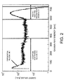
- FIG. 2 illustrates an energy spectrum of Cs-137 ⁇ -rays (661.6 keV) with a BGO scintillation detector.
- the scintillator 10 having a size of 10 mm ⁇ x 10 mm or less, preferably 1 mm ⁇ x 2 mm or less, more preferably 1 mm ⁇ x 1 mm or less, it is possible to increase the probability that Compton scattering electrons generated in the scintillator 10 itself are dissipated from the scintillator 10.
- the region (I) will present a distribution which depends on the shape and size of the scintillator 10, rather than a linear distribution.
- the region (I) assumes a distribution which depends on an interaction cross section between the electron and the scintillator 10, which is generally an exponential distribution. Accordingly, with a combination of this region (I) with the region (III) which also varies exponentially, computation of a dosage by counting ionizing radiation can be achieved.
- the size of the scintillator 10 it is possible to increase the probability that the Compton scattering electrons generated in the scintillator 10 itself are dissipated from the scintillator 10 to thereby change the region (I) to an exponential distribution, with substantially no light emission generated due to the photoelectric effect within the substance.
- the scintillator 10 is connected to an optical fiber 12 which transmits light that is converted from the ionizing radiation by the scintillator 10. It is also preferable that the optical fiber 12 is connected in a detachable manner by providing a connector in the middle thereof. This structure facilitates setting of the scintillator 10 at a desired position.
- the optical fiber 12 is connected to a photoelectron multiplier tube 14.
- the photoelectron multiplier tube 14 which is a photoelectric converter, converts light (a light signal) supplied from the optical fiber 12 into an electric signal in accordance with the light intensity.
- a signal amplifier 16 is connected to the photoelectron multiplier tube 14 for amplifying the electric signal supplied from the photoelectron multiplier tube 14.
- An output of the signal amplifier 16 is supplied to a discriminator 18, to which a threshold value is also input.
- the discriminator 18 discriminates, as an event, an electrical signal having a signal level which is a threshold value or greater, from other electrical signals input to the discriminator 18.
- the discriminator 18 aims at finally discriminating an electrical signal used for detecting an accurate dosage from electrical noise, and may therefore determine in comparison with detection performed by a high performance ionization chamber when specific ionizing radiation is incident.
- the discriminator 18 can be formed of a comparator and the like.
- the spectrum of adsorption energy in the scintillator 10 is represented by a pure exponential function, and if this assumption is established, no errors may be generated no matter what value is used for the threshold value.
- some errors will be generated by setting a certain threshold value. Specifically, as the threshold value becomes higher, the range of estimation is increased, resulting in a possibility of a greater error.
- counting should be performed more than the necessary number of times, leading to a possibility that the measuring device is saturated with too many pulses. It is therefore preferable that the threshold value is set to an appropriate value in consideration of the above.
- An output of the discriminator 18 is supplied to a counter 20, which counts the number of events discriminated by the discriminator 18.
- the counting result obtained by the counter 20 is supplied to a computer 22 where the count value of events is converted to a dosage, which is then displayed on the display 24.
- the computer 22 executes a program which is directly stored in a recording medium such as a hard disk within the computer 22, to perform the processing which will be described below.
- the program may be directly written in the computer 22, may be loaded from a CD, or may be supplied to the computer 22 through a communication line.
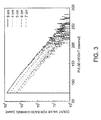
- the pulse height spectrum (a count value for each pulse height channel) of a light emission event of a plastic scintillator with respect to Ir-192 ⁇ -ray is a substantially exponential function.
- FIG. 3 illustrates results in a case where the distance to a ray source is shifted by 1 cm, from 3 cm to 7 cm. In each result, as the signal level (pulse height) of the light emission event becomes higher, the count value of the light emission event is exponentially decreased accordingly.
- a plastic scintillator BC490 manufactured by Saint-Gobain CDJ K.K. is used as the scintillator 10.
- a and "b" are constants defined based on the relationship shown in FIG. 3 .
- D W / ⁇ ⁇ en W / ⁇ ⁇ en Sc ⁇ C total b - a ⁇ ⁇ ⁇ t b 2 exp - b ⁇ E 0 - 1
- ( ⁇ en / ⁇ )[m 2 ⁇ kg -1 ] represents a mass energy transfer coefficient, and such a coefficient with subscript "Sc" indicates that of the scintillator 10 and the coefficient with subscript "W” indicates that of water. More specifically, in the first term of the right side of the formula (9), the dosage in the scintillator 10 is converted to a water absorbed dose.
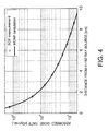
- FIG. 4 illustrates results of measuring a relationship (absorbed dose rate distribution) between a distance from a ray source and an absorbed dose rate ([cGy/min]) in water phantom in which an Ir-192 source for brachytherapy is employed, by using the device according to the present embodiment.
- the Monte Carlo N-Particle Transport Code (MCNP-4C) was used for comparison with the measurement results.
- the measurement results which match the MCNP-4C code very precisely could be obtained with respect to changes in dosages over two digits or more. Also, such a measurement over a wide range as shown is one of the features of the present embodiment.
- FIG. 5 illustrates a comparison between the dosage measurement of the present embodiment and the conventional dosage measurement.
- the dosage is obtained from the number of events equal to a threshold value or greater.
- highly precise detection can be achieved in a relatively simple manner concerning the scintillator 10 and a processing circuit thereof.
- a plastic scintillator which emits green light (about 490 nm) is used as the scintillator 10.
- the wavelength spectrum of the Cherenkov light expands to near the red light region (600 nm) depending on its intensity, and has a sufficient intensity even in the blue light region (about 420 nm).
- This nature is utilized to split light using a beam splitter which separates light, with the wavelength of 455 nm being used as a border, so that the Cherenkov light is determined when light of 455 nm or less and light of 455 nm or more is measured simultaneously and a signal is determined when only light of 455 nm or more is measured.
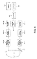
- FIG. 6 illustrates an example structure for this case.
- Light emitted by the scintillator 10 is transmitted, via the optical fiber 12, to the beam splitter 30 where the light is divided into light of 455 nm or less and light of 455 nm or more.
- the light of 455 nm or less is directed to a photoelectron multiplier tube 14-1, a signal amplifier 16-1, and a discriminator 18-1, where an event is detected, and a signal concerning the event which is detected is supplied to a comparison operator 32.
- the light of 455 nm or more is directed to a photoelectron multiplier tube 14-2, a signal amplifier 16-2, and a discriminator 18-2, where an event is detected, and a signal concerning the event which is detected is supplied to the comparison operator 32.
- the comparison operator 32 is formed by an anti-coincidence counter circuit. More specifically, the comparison operator 32 outputs no count signals when signals are supplied from both discriminators 18-1 and 18-2 at the same timing and outputs a count signal only when a necessary signal is supplied. It is assumed, for example, that, of a blue light emission signal B and a green light emission signal G, the light emission signal G is necessary. When only the G signal is supplied to the comparison operator 32 without the B signal being supplied simultaneously, the comparison operator 32 outputs a count signal. When only the B signal is supplied to the comparison operator 32, without the G signal being supplied simultaneously, or when the B signal and the G signal are input simultaneously, the comparison operator 32 does not output a count signal.
- a gate is formed by the B signal to allow the G signal to pass only when B signal is not present.
- the comparison operator 32 based on the signals supplied from the both discriminators 18-1 and 18-2, removes a signal of the Cherenkov light and outputs a count signal. Accordingly, the counter 20 can count the count signals supplied from the comparison operator 32, while eliminating the effects of the Cherenkov light.
- the light of 455 nm or less and the light of 455 nm or more separated by the beam splitter 30 does not necessarily have the same level, it is preferable to adopt different threshold values for the discriminators 18-1 and 18-2, so that appropriate determination can be performed.
- an amount of light emission at the scintillator 10 is converted to an electric current value (voltage value) by the photoelectron multiplier tube 14, and then the discriminator 18 is employed to discriminate only events with a threshold light emission amount or more, and the counter 20 further counts the number of events.
- the photoelectron multiplier tube 14, the discriminator 18, and the counter 20 are inexpensive, and therefore the present embodiment does not require an expensive micro ammeter as required in JP 2004-526155 A .
- the scintillator 10 need not have a large size and a smaller scintillator is preferable. More specifically, with the use of a small scintillator 10, the spatial resolution concerning a measurement value can be increased. For example, while a scintillator of 1 mm ⁇ x 10 mm is used in JP 2004-526155 A , a hemisphere scintillator having a diameter of about 1 mm, which is a scintillator about a thirtieth of the conventional scintillator, is used in the present embodiment. Consequently, the spatial resolution by measurement results is 20 times that of the conventional scintillator. It is therefore possible to detect and measure ⁇ -rays within a living body and also to accurately measure the dosage during radiotherapy, which could only be measured based on vague estimation in the conventional technology.
- the structure of a device can be simplified as described above, it is easy to provide a multi-channel structure in which a large number of scintillators 10 are provided to detect the radiation doses at a large number of positions.
Landscapes
- Health & Medical Sciences (AREA)
- Life Sciences & Earth Sciences (AREA)
- Biomedical Technology (AREA)
- General Physics & Mathematics (AREA)
- High Energy & Nuclear Physics (AREA)
- Molecular Biology (AREA)
- Spectroscopy & Molecular Physics (AREA)
- Engineering & Computer Science (AREA)
- Physics & Mathematics (AREA)
- Pathology (AREA)
- Nuclear Medicine, Radiotherapy & Molecular Imaging (AREA)
- Radiology & Medical Imaging (AREA)
- Animal Behavior & Ethology (AREA)
- General Health & Medical Sciences (AREA)
- Public Health (AREA)
- Veterinary Medicine (AREA)
- Measurement Of Radiation (AREA)
Abstract
Description
- The present invention relates to detection of ionizing radiation dosage using a scintillator.
- In the field of radiotherapy, an ionization chamber is generally used for measuring ionizing radiation. An ionization chamber is a measuring device which collects charges, generated at the time of ionization of air contained in a minute volume by radiation, by means of a high voltage of several hundreds of volts, and assesses a dosage from an amount of charges which are collected.
- On the other hand, solid-state detectors are also used as a means for measuring the dosage.
JP 2004-526155 A - Further,
WO 2005/008287 A discloses technology related to counting of thermal neutron flux using a scintillator. - In
JP 2004-526155 A - While the measures for increasing the amount of light emission (above (i)) can be achieved by increasing the size of the scintillator, a large size scintillator is disadvantageous in measurement in a very small region. Further, the above measures (ii) and (iii) would require expensive electrical equipment.
- A radiation dosimeter according to the present invention includes a scintillator which emits light by incident ionizing radiation, a photoelectric converter which converts light, which is output from the scintillator, to an electric current, a counter which counts the number of events, concerning an output from the photoelectric converter, having an intensity which is a predetermined threshold value or greater, and a dosage computing unit which converts a count value obtained by the counter to a dosage to obtain the dosage, based on a relationship in which a frequency of occurrence of each event exponentially decreases as the intensity of light of the event increases.
- Also, the present invention relates to a program for detecting the above-described dosage by a computer, and to a medium in which the program is recorded.
- According to the present invention, the number of events of light emission from a scintillator, which is substantially free from light emission caused by a photoelectric effect within the scintillator due to ionizing radiation, occurring with the light emission intensity exceeding a predetermined threshold value, is counted and converted to dosage. It is therefore possible to detect an ionizing radiation dosage in a wide range by utilizing a relatively small scintillator and a relatively simple circuit.
- These and other objects of the invention will be explained in the description below, in connection with the accompanying drawings, in which:
-
FIG. 1 is a diagram illustrating a structure of a radiation dosimeter according to an embodiment of the present invention; -
FIG. 2 is a diagram illustrating an energy spectrum of γ-rays with a BGO scintillation detector; -
FIG. 3 is a diagram illustrating a pulse-height distribution spectrum with a supermicro plastic scintillator (BC490) with respect to an Ir-192 ray source in water; -
FIG. 4 is a diagram illustrating measurement results of dosage distribution with an Ir-192 ray source in water phantom; -
FIG. 5 is a diagram illustrating a comparison between a conventional detection method (A) and a detection method according to the embodiment (B); and -
FIG. 6 is a diagram illustrating a structure according to another embodiment. - Preferred embodiments of the present invention will be described with reference to the drawings.
-
FIG. 1 is a diagram illustrating a structure of a radiation dosimeter according to an embodiment of the present invention. This radiation dosimeter measures a dosage during radiotherapy performed using X-rays and γ-rays. - A
scintillator 10, which is formed from a plastic scintillator, for example, converts ionizing radiation to light. According to this embodiment, as a large amount of light is not required, thescintillator 10 can be formed to have a small size of approximately 1 mm ϕ x 0.1 mm, for example. Compared to the conventional example in which a scintillator having a size of 1 mm ϕ x 10 mm is used, the size of thescintillator 10 in the present embodiment is approximately a hundredth, which results in an increase in the spatial of 100 times. Further, when a plurality ofscintillators 10 are provided, it is possible to detect an ionizing radiation dose at a plurality of positions. - Here, in the present embodiment, an organic scintillator, and particularly a plastic scintillator, is adopted as the
scintillator 10, so that the ionizing radiation is converted to light with substantially no light emission occurring due to a photoelectric effect within the substance by means of the ionizing radiation. - It should be noted that with the use of a scintillator containing a light element as a major component, similarly, substantially no light emission is caused by a photoelectric effect within the substance due to the ionizing radiation, as in the case of the plastic scintillator. Particularly, a scintillator containing a light element as a major component, whose emission delay time is 10 nanoseconds or less, is known, and the use of such a scintillator enables reliable separation of events and accurate counting of events.
- Further, it is possible to employ a scintillator formed of organic and inorganic layered perovskite type compounds, expressed by a general formula (CnH2n+1NH3)2pX4 (wherein X is halogen, n=3 to 10). This substance forms a multiple quantum well structure including an organic layer formed of alkylamine as a barrier layer and an inorganic layer formed of lead halide as a well layer. Excitons confined in the well layer of this substance emit light by irradiation with radiation. Further, a scintillator material, Li2O-B2O3:Ce3+, is also known for a scintillator for neutrons. As with the plastic scintillator, these scintillators are also capable of converting ionizing radiation to light with substantially no light emission caused by a photoelectric effect within the substances due to the ionizing radiation.
- In general, when γ-rays are measured with an inorganic scintillator, a large absorption energy peak appears due to a photoelectric effect (region (I) in
FIG. 2 ) and adsorption due to Compton scattering (region (II) inFIG. 2). FIG. 2 illustrates an energy spectrum of Cs-137 γ-rays (661.6 keV) with a BGO scintillation detector. - In the case of an organic scintillator, the energy peak due to the photoelectric effect as can be seen in the case of an inorganic scintillator does not appear, and only a spectrum due to Compton scattering is obtained.
- Further, by employing the
scintillator 10 having a size of 10 mm ϕ x 10 mm or less, preferably 1 mm ϕ x 2 mm or less, more preferably 1 mm ϕ x 1 mm or less, it is possible to increase the probability that Compton scattering electrons generated in thescintillator 10 itself are dissipated from thescintillator 10. At this time, the region (I) will present a distribution which depends on the shape and size of thescintillator 10, rather than a linear distribution. When the shape is a micro sphere, the region (I) assumes a distribution which depends on an interaction cross section between the electron and thescintillator 10, which is generally an exponential distribution. Accordingly, with a combination of this region (I) with the region (III) which also varies exponentially, computation of a dosage by counting ionizing radiation can be achieved. - In particular, by setting the size of the
scintillator 10 to 1 mm3 or less, it is possible to increase the probability that the Compton scattering electrons generated in thescintillator 10 itself are dissipated from thescintillator 10 to thereby change the region (I) to an exponential distribution, with substantially no light emission generated due to the photoelectric effect within the substance. - The
scintillator 10 is connected to anoptical fiber 12 which transmits light that is converted from the ionizing radiation by thescintillator 10. It is also preferable that theoptical fiber 12 is connected in a detachable manner by providing a connector in the middle thereof. This structure facilitates setting of thescintillator 10 at a desired position. - The
optical fiber 12 is connected to aphotoelectron multiplier tube 14. Thephotoelectron multiplier tube 14, which is a photoelectric converter, converts light (a light signal) supplied from theoptical fiber 12 into an electric signal in accordance with the light intensity. Asignal amplifier 16 is connected to thephotoelectron multiplier tube 14 for amplifying the electric signal supplied from thephotoelectron multiplier tube 14. - An output of the
signal amplifier 16 is supplied to adiscriminator 18, to which a threshold value is also input. Thediscriminator 18 discriminates, as an event, an electrical signal having a signal level which is a threshold value or greater, from other electrical signals input to thediscriminator 18. Here, thediscriminator 18 aims at finally discriminating an electrical signal used for detecting an accurate dosage from electrical noise, and may therefore determine in comparison with detection performed by a high performance ionization chamber when specific ionizing radiation is incident. Thediscriminator 18 can be formed of a comparator and the like. - In the present embodiment, it is assumed that the spectrum of adsorption energy in the
scintillator 10 is represented by a pure exponential function, and if this assumption is established, no errors may be generated no matter what value is used for the threshold value. Actually, however, as it is considered that the absorption energy spectrum is not a perfect exponential function, some errors will be generated by setting a certain threshold value. Specifically, as the threshold value becomes higher, the range of estimation is increased, resulting in a possibility of a greater error. On the other hand, as the threshold value decreases, counting should be performed more than the necessary number of times, leading to a possibility that the measuring device is saturated with too many pulses. It is therefore preferable that the threshold value is set to an appropriate value in consideration of the above. - An output of the
discriminator 18 is supplied to acounter 20, which counts the number of events discriminated by thediscriminator 18. - The counting result obtained by the
counter 20 is supplied to acomputer 22 where the count value of events is converted to a dosage, which is then displayed on thedisplay 24. Thecomputer 22 executes a program which is directly stored in a recording medium such as a hard disk within thecomputer 22, to perform the processing which will be described below. Alternatively, the program may be directly written in thecomputer 22, may be loaded from a CD, or may be supplied to thecomputer 22 through a communication line. - The conversion from the count value of events to a dosage performed by the
computer 22 will be described. - Assuming that when the energy applied to the
scintillator 10 is E∼E+dE, the number of events is CSc(E), the dosage (energy) at thescintillator 10 is obtained by multiplying the event level with the energy of 0 to ∞ by the number of events, and is represented as follows:
- As shown in
FIG. 3 , the pulse height spectrum (a count value for each pulse height channel) of a light emission event of a plastic scintillator with respect to Ir-192 γ-ray is a substantially exponential function.FIG. 3 illustrates results in a case where the distance to a ray source is shifted by 1 cm, from 3 cm to 7 cm. In each result, as the signal level (pulse height) of the light emission event becomes higher, the count value of the light emission event is exponentially decreased accordingly. Here, a plastic scintillator BC490 (manufactured by Saint-Gobain CDJ K.K.) is used as thescintillator 10. - Accordingly, the number of events CSc(E) can be determined by the energy level and can be approximated as follows, provided that a measurement time is Δt:

FIG. 3 . - Consequently, the above formula (1) can be expressed as follows by using the above formula (2):

- On the other hand, application of energy by electrons with energy of E0 or more, i.e. the total number of light emission events of the
scintillator 10, is obtained by integration of the number of events CSc(E) for each energy in the above formula (2) with respect to the energy E0 or more, and can be represented as follows:
- Here, the following formula (5) is known as a mathematical formula of integration by parts:


- Accordingly, the dosage DSc at the
scintillator 10 can be represented as follows:
- Further, the absorbed dose in water DW is obtained from the above formulas (1) and (8) as follows:

- In the above formula, (µen/ρ)[m2·kg-1] represents a mass energy transfer coefficient, and such a coefficient with subscript "Sc" indicates that of the
scintillator 10 and the coefficient with subscript "W" indicates that of water. More specifically, in the first term of the right side of the formula (9), the dosage in thescintillator 10 is converted to a water absorbed dose. - Here, provided that the following is defined:


-
FIG. 4 illustrates results of measuring a relationship (absorbed dose rate distribution) between a distance from a ray source and an absorbed dose rate ([cGy/min]) in water phantom in which an Ir-192 source for brachytherapy is employed, by using the device according to the present embodiment. - Here, the Monte Carlo N-Particle Transport Code (MCNP-4C) was used for comparison with the measurement results. As can be seen from
FIG. 4 , the measurement results which match the MCNP-4C code very precisely could be obtained with respect to changes in dosages over two digits or more. Also, such a measurement over a wide range as shown is one of the features of the present embodiment. -
FIG. 5 illustrates a comparison between the dosage measurement of the present embodiment and the conventional dosage measurement. As shown, while in the conventional technology integration of dosage is performed to detect the dosage as an average electric current amount, in the present embodiment, the dosage is obtained from the number of events equal to a threshold value or greater. With the method of the present embodiment, highly precise detection can be achieved in a relatively simple manner concerning thescintillator 10 and a processing circuit thereof. - Further, effects of the Cherenkov light on the measurement as described in the above-mentioned
JP 2004-526155 A - First, a plastic scintillator which emits green light (about 490 nm) is used as the
scintillator 10. Here, the wavelength spectrum of the Cherenkov light expands to near the red light region (600 nm) depending on its intensity, and has a sufficient intensity even in the blue light region (about 420 nm). This nature is utilized to split light using a beam splitter which separates light, with the wavelength of 455 nm being used as a border, so that the Cherenkov light is determined when light of 455 nm or less and light of 455 nm or more is measured simultaneously and a signal is determined when only light of 455 nm or more is measured. Then, the Cherenkov light which is determined is excluded from events, so that the effects of Cherenkov light can be removed in a simple manner. Also, this method in which, contrary to the technology described inJP 2004-526155 A -
FIG. 6 illustrates an example structure for this case. Light emitted by thescintillator 10 is transmitted, via theoptical fiber 12, to thebeam splitter 30 where the light is divided into light of 455 nm or less and light of 455 nm or more. The light of 455 nm or less is directed to a photoelectron multiplier tube 14-1, a signal amplifier 16-1, and a discriminator 18-1, where an event is detected, and a signal concerning the event which is detected is supplied to acomparison operator 32. On the other hand, the light of 455 nm or more is directed to a photoelectron multiplier tube 14-2, a signal amplifier 16-2, and a discriminator 18-2, where an event is detected, and a signal concerning the event which is detected is supplied to thecomparison operator 32. - Here, the
comparison operator 32 is formed by an anti-coincidence counter circuit. More specifically, thecomparison operator 32 outputs no count signals when signals are supplied from both discriminators 18-1 and 18-2 at the same timing and outputs a count signal only when a necessary signal is supplied. It is assumed, for example, that, of a blue light emission signal B and a green light emission signal G, the light emission signal G is necessary. When only the G signal is supplied to thecomparison operator 32 without the B signal being supplied simultaneously, thecomparison operator 32 outputs a count signal. When only the B signal is supplied to thecomparison operator 32, without the G signal being supplied simultaneously, or when the B signal and the G signal are input simultaneously, thecomparison operator 32 does not output a count signal. In other words, a gate is formed by the B signal to allow the G signal to pass only when B signal is not present. With this structure, thecomparison operator 32, based on the signals supplied from the both discriminators 18-1 and 18-2, removes a signal of the Cherenkov light and outputs a count signal. Accordingly, thecounter 20 can count the count signals supplied from thecomparison operator 32, while eliminating the effects of the Cherenkov light. - Here, as the light of 455 nm or less and the light of 455 nm or more separated by the
beam splitter 30 does not necessarily have the same level, it is preferable to adopt different threshold values for the discriminators 18-1 and 18-2, so that appropriate determination can be performed. - As described above, in the present embodiment, an amount of light emission at the
scintillator 10 is converted to an electric current value (voltage value) by thephotoelectron multiplier tube 14, and then thediscriminator 18 is employed to discriminate only events with a threshold light emission amount or more, and thecounter 20 further counts the number of events. In general, thephotoelectron multiplier tube 14, thediscriminator 18, and thecounter 20 are inexpensive, and therefore the present embodiment does not require an expensive micro ammeter as required inJP 2004-526155 A - Further, in the present embodiment, the
scintillator 10 need not have a large size and a smaller scintillator is preferable. More specifically, with the use of asmall scintillator 10, the spatial resolution concerning a measurement value can be increased. For example, while a scintillator of 1 mm ϕ x 10 mm is used inJP 2004-526155 A - Further, by increasing the probability that Compton scattering electrons generated by the scintillator itself are dissipated from the scintillator, an exponential distribution can be obtained, so that accurate detection of the radiation dose can be performed.
- Also, because the structure of a device can be simplified as described above, it is easy to provide a multi-channel structure in which a large number of
scintillators 10 are provided to detect the radiation doses at a large number of positions.
Claims (10)
- A radiation dosimeter, comprising;a scintillator which emits light by incident ionizing radiation;a photoelectric converter which converts light, which is an output of the scintillator, to an electric current;a counter which counts the number of events, concerning an output from the photoelectric converter, having an intensity that is a predetermined threshold value or greater; anda dosage computing unit which converts a count value obtained by the counter to a dosage to obtain the dosage, based on a relationship in which a frequency of occurrence of each event exponentially decreases as the intensity of light of the event increases.
- The radiation dosimeter according to Claim 1, wherein
the scintillator is a plastic scintillator. - The radiation dosimeter according to Claim 1, wherein
the scintillator contains a light element as a major component and has an emission decay time of 10 nanosecond or less. - The radiation dosimeter according to Claim 1, wherein
a volume of the scintillator is 1 mm3 or less. - The radiation dosimeter according to any one of Claims 1 to 4, wherein
the dosage computing unit computes a dosage DSc in the scintillator based on the following formula:
- The radiation dosimeter according to Claim 1, wherein Cherenkov light and light emission by the scintillator are discriminated from each other based on whether light emission at a plurality of different wavelengths occurs simultaneously or only light emission at a single specific wavelength occurs, and counting is performed so that light emission other than light emission by the scintillator is excluded.
- A radiation dose computing program for computing a dosage by a scintillator, the program causing a computer to execute a process comprising:accepting a count value obtained by counting a number of events having an intensity of a predetermined threshold value or greater, concerning an electrical signal which is converted to an electric current from a light output from the scintillator which emits light by incident ionizing radiation; andconverting the count value which is accepted to a dosage based on a relationship in which a frequency of occurrence of each event exponentially decreases as the intensity of light of the event increases, thereby obtaining the dosage.
- The radiation dose computing program according to Claim 7, wherein
the relationship which is prestored is based on the following formula:
- A medium storing a radiation dose computing program for computing a dosage by a scintillator, the program causing a computer to execute a process comprising:accepting a count value obtained by counting a number of events having an intensity of a predetermined threshold value or greater, concerning an electrical signal which is converted to an electric current from a light output from the scintillator which emits light by incident ionizing radiation; andconverting the count value which is accepted to a dosage based on a relationship in which a frequency of occurrence of each event exponentially decreases as the intensity of light of the event increases, thereby obtaining the dosage.
- The medium storing a radiation dose computing program according to Claim 9, wherein
the relationship which is prestored is based on the following formula:
Applications Claiming Priority (2)
| Application Number | Priority Date | Filing Date | Title |
|---|---|---|---|
| JP2006261241 | 2006-09-26 | ||
| PCT/JP2007/068675 WO2008038662A1 (en) | 2006-09-26 | 2007-09-26 | Radiation dosimeter and radiation dose computing program |
Publications (3)
| Publication Number | Publication Date |
|---|---|
| EP2077457A1 true EP2077457A1 (en) | 2009-07-08 |
| EP2077457A4 EP2077457A4 (en) | 2016-08-17 |
| EP2077457B1 EP2077457B1 (en) | 2018-11-14 |
Family
ID=39230098
Family Applications (1)
| Application Number | Title | Priority Date | Filing Date |
|---|---|---|---|
| EP07807890.4A Not-in-force EP2077457B1 (en) | 2006-09-26 | 2007-09-26 | Radiation dosimeter and radiation dose computing program |
Country Status (4)
| Country | Link |
|---|---|
| US (1) | US8044357B2 (en) |
| EP (1) | EP2077457B1 (en) |
| JP (1) | JP4766407B2 (en) |
| WO (1) | WO2008038662A1 (en) |
Cited By (1)
| Publication number | Priority date | Publication date | Assignee | Title |
|---|---|---|---|---|
| US9000401B2 (en) | 2010-07-07 | 2015-04-07 | Institut National D'optique | Fiber optic radiochromic dosimeter probe and method to make the same |
Families Citing this family (17)
| Publication number | Priority date | Publication date | Assignee | Title |
|---|---|---|---|---|
| US9155909B2 (en) | 2009-03-24 | 2015-10-13 | National University Corporation Hokkaido University | Radiation therapy apparatus |
| US8604440B2 (en) | 2010-03-09 | 2013-12-10 | The University Of Chicago | Use of flat panel microchannel photomultipliers in sampling calorimeters with timing |
| US20120292517A1 (en) * | 2011-05-19 | 2012-11-22 | Washington University | Real-time imaging dosimeter systems and method |
| CA2874397C (en) * | 2011-05-24 | 2019-09-24 | Universite Laval | Methods and apparatus for optically encoded position multiple-point scintillation detector using a single collecting light guide |
| US8658978B2 (en) | 2011-12-29 | 2014-02-25 | Raytheon Company | Methods and apparatus for a radiation monitor |
| US9958402B2 (en) * | 2012-02-23 | 2018-05-01 | Steven M. Ebstein | Dosimetric scintillating screen detector for charged particle radiotherapy quality assurance (QA) |
| JP5791546B2 (en) * | 2012-02-29 | 2015-10-07 | 株式会社日立製作所 | Calibration method of radiation measuring apparatus and particle beam therapy apparatus |
| WO2013184204A2 (en) | 2012-03-22 | 2013-12-12 | Duke University | Linear-response nanocrystal scintillators and methods of using the same |
| CN103018763B (en) * | 2012-12-12 | 2015-08-26 | 中国科学院国家天文台 | The sniffer of gamma ray and cosmic ray and method |
| CN102981180B (en) * | 2012-12-12 | 2015-08-26 | 中国科学院国家天文台 | Water Cerenkov light high-energy particle detector |
| JP2014241543A (en) * | 2013-06-12 | 2014-12-25 | 株式会社東芝 | Photo-detection device and ct device |
| RU2665330C2 (en) * | 2013-11-08 | 2018-08-29 | Шлюмбергер Текнолоджи Б.В. | Spectral analysis with spectral deconvolution |
| JP6452425B2 (en) * | 2014-12-11 | 2019-01-16 | 株式会社日立製作所 | Radiation monitor |
| JP6730702B2 (en) * | 2015-02-12 | 2020-07-29 | 国立大学法人北海道大学 | Scintillator and radiation dosimeter using the same |
| US10386499B2 (en) * | 2015-11-12 | 2019-08-20 | Centre National De La Recherche Scientifique | Device for determining a deposited dose and associated method |
| JP6817162B2 (en) * | 2017-07-07 | 2021-01-20 | 株式会社日立製作所 | Radiation monitoring equipment and radiation therapy equipment, and radiation monitoring methods |
| CN109975855B (en) * | 2019-04-02 | 2023-09-19 | 东华理工大学 | A wide-range intelligent X-γ dose rate meter device based on Bluetooth technology |
Family Cites Families (8)
| Publication number | Priority date | Publication date | Assignee | Title |
|---|---|---|---|---|
| JPS51124981A (en) * | 1975-04-24 | 1976-10-30 | Japan Atom Energy Res Inst | A gamma ray scintillation detector |
| JP2001056381A (en) * | 1999-08-20 | 2001-02-27 | Mitsubishi Electric Corp | Local dosimeter and medical device using the same |
| US6320935B1 (en) * | 2000-02-28 | 2001-11-20 | X-Technologies, Ltd. | Dosimeter for a miniature energy transducer for emitting X-ray radiation |
| FR2822239B1 (en) | 2001-03-15 | 2003-09-26 | Centre Nat Rech Scient | IRRADIATION DOSE MEASUREMENT METHOD |
| JP2003194953A (en) | 2001-12-25 | 2003-07-09 | Toden Kogyo Co Ltd | Radiation measurement program and radiation-measuring apparatus |
| US7583775B2 (en) * | 2002-08-14 | 2009-09-01 | Kabushiki Kaisha Toshiba | Concentrated irradiation type radiotherapy apparatus |
| JP2004191327A (en) | 2002-12-13 | 2004-07-08 | Natl Inst Of Radiological Sciences | Gamma ray detector |
| WO2005008287A1 (en) | 2003-07-18 | 2005-01-27 | Toudai Tlo, Ltd. | Thermal netron flux monitor |
-
2007
- 2007-09-26 JP JP2008536391A patent/JP4766407B2/en active Active
- 2007-09-26 US US12/443,101 patent/US8044357B2/en active Active
- 2007-09-26 WO PCT/JP2007/068675 patent/WO2008038662A1/en not_active Ceased
- 2007-09-26 EP EP07807890.4A patent/EP2077457B1/en not_active Not-in-force
Non-Patent Citations (1)
| Title |
|---|
| See references of WO2008038662A1 * |
Cited By (1)
| Publication number | Priority date | Publication date | Assignee | Title |
|---|---|---|---|---|
| US9000401B2 (en) | 2010-07-07 | 2015-04-07 | Institut National D'optique | Fiber optic radiochromic dosimeter probe and method to make the same |
Also Published As
| Publication number | Publication date |
|---|---|
| EP2077457B1 (en) | 2018-11-14 |
| JP4766407B2 (en) | 2011-09-07 |
| JPWO2008038662A1 (en) | 2010-01-28 |
| US8044357B2 (en) | 2011-10-25 |
| US20100038547A1 (en) | 2010-02-18 |
| EP2077457A4 (en) | 2016-08-17 |
| WO2008038662A1 (en) | 2008-04-03 |
Similar Documents
| Publication | Publication Date | Title |
|---|---|---|
| EP2077457B1 (en) | Radiation dosimeter and radiation dose computing program | |
| US6876711B2 (en) | Neutron detector utilizing sol-gel absorber and activation disk | |
| JP5027124B2 (en) | Method and apparatus for detection of co-generated radiation in a single transducer by pulse waveform analysis | |
| US8084748B2 (en) | Radioactive material detecting and identifying device and method | |
| US9244178B2 (en) | Method for determining the irradiation dose deposited in a scintillator by ionising radiation and associated device | |
| CN102498416A (en) | Apparatus and method for neutron detection with neutron-absorbing calorimetric gamma detectors | |
| US11163076B2 (en) | Method for the detection of neutrons with scintillation detectors used for gamma ray spectroscopy | |
| US10386499B2 (en) | Device for determining a deposited dose and associated method | |
| RU2189057C2 (en) | Scintillation detector of neutron and gamma radiation | |
| RU2143711C1 (en) | Detector for registration of ionizing radiation | |
| JP2001056381A (en) | Local dosimeter and medical device using the same | |
| JP4893950B2 (en) | Radioactivity absolute measurement method, radiation detector assembly detection efficiency determination method, and radiation measurement apparatus calibration method | |
| US8766206B2 (en) | Neutron detection based on energy spectrum characteristics | |
| JP4061367B2 (en) | ZnS (Ag) scintillation detector | |
| Farsoni et al. | A system for simultaneous beta and gamma spectroscopy | |
| JP4151935B2 (en) | Radiation measurement equipment | |
| EP3567404B1 (en) | Method and device for the measurement of high dose rates of ionizing radiation | |
| Del Guerra et al. | Radiation measurement | |
| Farsoni et al. | MCNP analysis of a multilayer phoswich detector for β-particle dosimetry and spectroscopy | |
| JP2012242369A (en) | Radiation detector | |
| Urbański et al. | Review of X-ray detection systems | |
| Tancioni et al. | Gamma dose rate monitoring using a Silicon Photomultiplier-based plastic scintillation detector | |
| JP7750528B2 (en) | Signal processing system, positron emission tomography apparatus, and positron emission tomography method | |
| Mo et al. | The influence of rejection of a fraction of the single photoelectron peak in liquid scintillation counting | |
| Owojori et al. | Energy Calibration Determination For Nai (Tl) Detectors Using Gamma Radionuclide Sources With High Beta Plus |
Legal Events
| Date | Code | Title | Description |
|---|---|---|---|
| PUAI | Public reference made under article 153(3) epc to a published international application that has entered the european phase |
Free format text: ORIGINAL CODE: 0009012 |
|
| 17P | Request for examination filed |
Effective date: 20090416 |
|
| AK | Designated contracting states |
Kind code of ref document: A1 Designated state(s): AT BE BG CH CY CZ DE DK EE ES FI FR GB GR HU IE IS IT LI LT LU LV MC MT NL PL PT RO SE SI SK TR |
|
| DAX | Request for extension of the european patent (deleted) | ||
| RA4 | Supplementary search report drawn up and despatched (corrected) |
Effective date: 20160715 |
|
| RIC1 | Information provided on ipc code assigned before grant |
Ipc: A61N 5/10 20060101ALI20160712BHEP Ipc: G01T 1/203 20060101ALI20160712BHEP Ipc: G01T 1/02 20060101ALI20160712BHEP Ipc: G01T 1/20 20060101AFI20160712BHEP |
|
| GRAP | Despatch of communication of intention to grant a patent |
Free format text: ORIGINAL CODE: EPIDOSNIGR1 |
|
| STAA | Information on the status of an ep patent application or granted ep patent |
Free format text: STATUS: GRANT OF PATENT IS INTENDED |
|
| INTG | Intention to grant announced |
Effective date: 20180605 |
|
| GRAS | Grant fee paid |
Free format text: ORIGINAL CODE: EPIDOSNIGR3 |
|
| GRAA | (expected) grant |
Free format text: ORIGINAL CODE: 0009210 |
|
| STAA | Information on the status of an ep patent application or granted ep patent |
Free format text: STATUS: THE PATENT HAS BEEN GRANTED |
|
| RAP1 | Party data changed (applicant data changed or rights of an application transferred) |
Owner name: NATIONAL UNIVERSITY CORPORATION HOKKAIDO UNIVERSIT |
|
| RIN1 | Information on inventor provided before grant (corrected) |
Inventor name: ISHIKAWA, MASAYORI |
|
| AK | Designated contracting states |
Kind code of ref document: B1 Designated state(s): AT BE BG CH CY CZ DE DK EE ES FI FR GB GR HU IE IS IT LI LT LU LV MC MT NL PL PT RO SE SI SK TR |
|
| REG | Reference to a national code |
Ref country code: GB Ref legal event code: FG4D |
|
| REG | Reference to a national code |
Ref country code: CH Ref legal event code: EP Ref country code: AT Ref legal event code: REF Ref document number: 1065488 Country of ref document: AT Kind code of ref document: T Effective date: 20181115 |
|
| REG | Reference to a national code |
Ref country code: DE Ref legal event code: R096 Ref document number: 602007056833 Country of ref document: DE |
|
| REG | Reference to a national code |
Ref country code: IE Ref legal event code: FG4D |
|
| REG | Reference to a national code |
Ref country code: NL Ref legal event code: MP Effective date: 20181114 |
|
| REG | Reference to a national code |
Ref country code: LT Ref legal event code: MG4D |
|
| REG | Reference to a national code |
Ref country code: AT Ref legal event code: MK05 Ref document number: 1065488 Country of ref document: AT Kind code of ref document: T Effective date: 20181114 |
|
| PG25 | Lapsed in a contracting state [announced via postgrant information from national office to epo] |
Ref country code: BG Free format text: LAPSE BECAUSE OF FAILURE TO SUBMIT A TRANSLATION OF THE DESCRIPTION OR TO PAY THE FEE WITHIN THE PRESCRIBED TIME-LIMIT Effective date: 20190214 Ref country code: AT Free format text: LAPSE BECAUSE OF FAILURE TO SUBMIT A TRANSLATION OF THE DESCRIPTION OR TO PAY THE FEE WITHIN THE PRESCRIBED TIME-LIMIT Effective date: 20181114 Ref country code: LV Free format text: LAPSE BECAUSE OF FAILURE TO SUBMIT A TRANSLATION OF THE DESCRIPTION OR TO PAY THE FEE WITHIN THE PRESCRIBED TIME-LIMIT Effective date: 20181114 Ref country code: FI Free format text: LAPSE BECAUSE OF FAILURE TO SUBMIT A TRANSLATION OF THE DESCRIPTION OR TO PAY THE FEE WITHIN THE PRESCRIBED TIME-LIMIT Effective date: 20181114 Ref country code: IS Free format text: LAPSE BECAUSE OF FAILURE TO SUBMIT A TRANSLATION OF THE DESCRIPTION OR TO PAY THE FEE WITHIN THE PRESCRIBED TIME-LIMIT Effective date: 20190314 Ref country code: LT Free format text: LAPSE BECAUSE OF FAILURE TO SUBMIT A TRANSLATION OF THE DESCRIPTION OR TO PAY THE FEE WITHIN THE PRESCRIBED TIME-LIMIT Effective date: 20181114 Ref country code: ES Free format text: LAPSE BECAUSE OF FAILURE TO SUBMIT A TRANSLATION OF THE DESCRIPTION OR TO PAY THE FEE WITHIN THE PRESCRIBED TIME-LIMIT Effective date: 20181114 |
|
| PG25 | Lapsed in a contracting state [announced via postgrant information from national office to epo] |
Ref country code: GR Free format text: LAPSE BECAUSE OF FAILURE TO SUBMIT A TRANSLATION OF THE DESCRIPTION OR TO PAY THE FEE WITHIN THE PRESCRIBED TIME-LIMIT Effective date: 20190215 Ref country code: PT Free format text: LAPSE BECAUSE OF FAILURE TO SUBMIT A TRANSLATION OF THE DESCRIPTION OR TO PAY THE FEE WITHIN THE PRESCRIBED TIME-LIMIT Effective date: 20190314 Ref country code: NL Free format text: LAPSE BECAUSE OF FAILURE TO SUBMIT A TRANSLATION OF THE DESCRIPTION OR TO PAY THE FEE WITHIN THE PRESCRIBED TIME-LIMIT Effective date: 20181114 Ref country code: SE Free format text: LAPSE BECAUSE OF FAILURE TO SUBMIT A TRANSLATION OF THE DESCRIPTION OR TO PAY THE FEE WITHIN THE PRESCRIBED TIME-LIMIT Effective date: 20181114 |
|
| PG25 | Lapsed in a contracting state [announced via postgrant information from national office to epo] |
Ref country code: PL Free format text: LAPSE BECAUSE OF FAILURE TO SUBMIT A TRANSLATION OF THE DESCRIPTION OR TO PAY THE FEE WITHIN THE PRESCRIBED TIME-LIMIT Effective date: 20181114 Ref country code: CZ Free format text: LAPSE BECAUSE OF FAILURE TO SUBMIT A TRANSLATION OF THE DESCRIPTION OR TO PAY THE FEE WITHIN THE PRESCRIBED TIME-LIMIT Effective date: 20181114 Ref country code: IT Free format text: LAPSE BECAUSE OF FAILURE TO SUBMIT A TRANSLATION OF THE DESCRIPTION OR TO PAY THE FEE WITHIN THE PRESCRIBED TIME-LIMIT Effective date: 20181114 Ref country code: DK Free format text: LAPSE BECAUSE OF FAILURE TO SUBMIT A TRANSLATION OF THE DESCRIPTION OR TO PAY THE FEE WITHIN THE PRESCRIBED TIME-LIMIT Effective date: 20181114 |
|
| REG | Reference to a national code |
Ref country code: DE Ref legal event code: R097 Ref document number: 602007056833 Country of ref document: DE |
|
| PG25 | Lapsed in a contracting state [announced via postgrant information from national office to epo] |
Ref country code: EE Free format text: LAPSE BECAUSE OF FAILURE TO SUBMIT A TRANSLATION OF THE DESCRIPTION OR TO PAY THE FEE WITHIN THE PRESCRIBED TIME-LIMIT Effective date: 20181114 Ref country code: SK Free format text: LAPSE BECAUSE OF FAILURE TO SUBMIT A TRANSLATION OF THE DESCRIPTION OR TO PAY THE FEE WITHIN THE PRESCRIBED TIME-LIMIT Effective date: 20181114 Ref country code: RO Free format text: LAPSE BECAUSE OF FAILURE TO SUBMIT A TRANSLATION OF THE DESCRIPTION OR TO PAY THE FEE WITHIN THE PRESCRIBED TIME-LIMIT Effective date: 20181114 |
|
| PLBE | No opposition filed within time limit |
Free format text: ORIGINAL CODE: 0009261 |
|
| STAA | Information on the status of an ep patent application or granted ep patent |
Free format text: STATUS: NO OPPOSITION FILED WITHIN TIME LIMIT |
|
| 26N | No opposition filed |
Effective date: 20190815 |
|
| PG25 | Lapsed in a contracting state [announced via postgrant information from national office to epo] |
Ref country code: SI Free format text: LAPSE BECAUSE OF FAILURE TO SUBMIT A TRANSLATION OF THE DESCRIPTION OR TO PAY THE FEE WITHIN THE PRESCRIBED TIME-LIMIT Effective date: 20181114 |
|
| PG25 | Lapsed in a contracting state [announced via postgrant information from national office to epo] |
Ref country code: TR Free format text: LAPSE BECAUSE OF FAILURE TO SUBMIT A TRANSLATION OF THE DESCRIPTION OR TO PAY THE FEE WITHIN THE PRESCRIBED TIME-LIMIT Effective date: 20181114 |
|
| PG25 | Lapsed in a contracting state [announced via postgrant information from national office to epo] |
Ref country code: MC Free format text: LAPSE BECAUSE OF FAILURE TO SUBMIT A TRANSLATION OF THE DESCRIPTION OR TO PAY THE FEE WITHIN THE PRESCRIBED TIME-LIMIT Effective date: 20181114 |
|
| REG | Reference to a national code |
Ref country code: CH Ref legal event code: PL |
|
| PG25 | Lapsed in a contracting state [announced via postgrant information from national office to epo] |
Ref country code: CH Free format text: LAPSE BECAUSE OF NON-PAYMENT OF DUE FEES Effective date: 20190930 Ref country code: LU Free format text: LAPSE BECAUSE OF NON-PAYMENT OF DUE FEES Effective date: 20190926 Ref country code: IE Free format text: LAPSE BECAUSE OF NON-PAYMENT OF DUE FEES Effective date: 20190926 Ref country code: LI Free format text: LAPSE BECAUSE OF NON-PAYMENT OF DUE FEES Effective date: 20190930 |
|
| REG | Reference to a national code |
Ref country code: BE Ref legal event code: MM Effective date: 20190930 |
|
| PG25 | Lapsed in a contracting state [announced via postgrant information from national office to epo] |
Ref country code: BE Free format text: LAPSE BECAUSE OF NON-PAYMENT OF DUE FEES Effective date: 20190930 |
|
| PG25 | Lapsed in a contracting state [announced via postgrant information from national office to epo] |
Ref country code: CY Free format text: LAPSE BECAUSE OF FAILURE TO SUBMIT A TRANSLATION OF THE DESCRIPTION OR TO PAY THE FEE WITHIN THE PRESCRIBED TIME-LIMIT Effective date: 20181114 |
|
| PG25 | Lapsed in a contracting state [announced via postgrant information from national office to epo] |
Ref country code: HU Free format text: LAPSE BECAUSE OF FAILURE TO SUBMIT A TRANSLATION OF THE DESCRIPTION OR TO PAY THE FEE WITHIN THE PRESCRIBED TIME-LIMIT; INVALID AB INITIO Effective date: 20070926 Ref country code: MT Free format text: LAPSE BECAUSE OF FAILURE TO SUBMIT A TRANSLATION OF THE DESCRIPTION OR TO PAY THE FEE WITHIN THE PRESCRIBED TIME-LIMIT Effective date: 20181114 |
|
| P01 | Opt-out of the competence of the unified patent court (upc) registered |
Effective date: 20230524 |
|
| PGFP | Annual fee paid to national office [announced via postgrant information from national office to epo] |
Ref country code: GB Payment date: 20230920 Year of fee payment: 17 |
|
| PGFP | Annual fee paid to national office [announced via postgrant information from national office to epo] |
Ref country code: FR Payment date: 20230928 Year of fee payment: 17 Ref country code: DE Payment date: 20230920 Year of fee payment: 17 |
|
| REG | Reference to a national code |
Ref country code: DE Ref legal event code: R119 Ref document number: 602007056833 Country of ref document: DE |
|
| GBPC | Gb: european patent ceased through non-payment of renewal fee |
Effective date: 20240926 |
|
| PG25 | Lapsed in a contracting state [announced via postgrant information from national office to epo] |
Ref country code: DE Free format text: LAPSE BECAUSE OF NON-PAYMENT OF DUE FEES Effective date: 20250401 |
|
| PG25 | Lapsed in a contracting state [announced via postgrant information from national office to epo] |
Ref country code: GB Free format text: LAPSE BECAUSE OF NON-PAYMENT OF DUE FEES Effective date: 20240926 |
|
| PG25 | Lapsed in a contracting state [announced via postgrant information from national office to epo] |
Ref country code: FR Free format text: LAPSE BECAUSE OF NON-PAYMENT OF DUE FEES Effective date: 20240930 |