EP2077233A1 - Method and arrangement for placing rolls of wrapping material and for leading the wrapping material in a roll packing machine - Google Patents
Method and arrangement for placing rolls of wrapping material and for leading the wrapping material in a roll packing machine Download PDFInfo
- Publication number
- EP2077233A1 EP2077233A1 EP08170684A EP08170684A EP2077233A1 EP 2077233 A1 EP2077233 A1 EP 2077233A1 EP 08170684 A EP08170684 A EP 08170684A EP 08170684 A EP08170684 A EP 08170684A EP 2077233 A1 EP2077233 A1 EP 2077233A1
- Authority
- EP
- European Patent Office
- Prior art keywords
- roll
- packed
- wrapped
- wrap
- rolls
- Prior art date
- Legal status (The legal status is an assumption and is not a legal conclusion. Google has not performed a legal analysis and makes no representation as to the accuracy of the status listed.)
- Granted
Links
Images
Classifications
-
- B—PERFORMING OPERATIONS; TRANSPORTING
- B65—CONVEYING; PACKING; STORING; HANDLING THIN OR FILAMENTARY MATERIAL
- B65B—MACHINES, APPARATUS OR DEVICES FOR, OR METHODS OF, PACKAGING ARTICLES OR MATERIALS; UNPACKING
- B65B25/00—Packaging other articles presenting special problems
- B65B25/14—Packaging paper or like sheets, envelopes, or newspapers, in flat, folded, or rolled form
- B65B25/146—Packaging paper or like sheets, envelopes, or newspapers, in flat, folded, or rolled form packaging rolled-up articles
- B65B25/148—Jumbo paper rolls
-
- B—PERFORMING OPERATIONS; TRANSPORTING
- B65—CONVEYING; PACKING; STORING; HANDLING THIN OR FILAMENTARY MATERIAL
- B65B—MACHINES, APPARATUS OR DEVICES FOR, OR METHODS OF, PACKAGING ARTICLES OR MATERIALS; UNPACKING
- B65B11/00—Wrapping, e.g. partially or wholly enclosing, articles or quantities of material, in strips, sheets or blanks, of flexible material
- B65B11/04—Wrapping, e.g. partially or wholly enclosing, articles or quantities of material, in strips, sheets or blanks, of flexible material the articles being rotated
-
- B—PERFORMING OPERATIONS; TRANSPORTING
- B65—CONVEYING; PACKING; STORING; HANDLING THIN OR FILAMENTARY MATERIAL
- B65B—MACHINES, APPARATUS OR DEVICES FOR, OR METHODS OF, PACKAGING ARTICLES OR MATERIALS; UNPACKING
- B65B11/00—Wrapping, e.g. partially or wholly enclosing, articles or quantities of material, in strips, sheets or blanks, of flexible material
- B65B11/56—Rolling articles with wrappers along a supporting surface
-
- B—PERFORMING OPERATIONS; TRANSPORTING
- B65—CONVEYING; PACKING; STORING; HANDLING THIN OR FILAMENTARY MATERIAL
- B65B—MACHINES, APPARATUS OR DEVICES FOR, OR METHODS OF, PACKAGING ARTICLES OR MATERIALS; UNPACKING
- B65B41/00—Supplying or feeding container-forming sheets or wrapping material
- B65B41/12—Feeding webs from rolls
- B65B41/16—Feeding webs from rolls by rollers
Definitions
- This invention relates to a method for leading the wrap of wrapped rolls in a packing machine from a wrapped roll to a roll being packed in the packing of paper, board and other fibrous rolls.
- the invention also relates to an arrangement for implementing the method.
- the packing wrap can be wrapped around the roll in three ways. If there are sufficiently wrapped rolls of different widths available, only one wrap layer covering the whole roll length is wrapped around the roll or roll group being packed. This way of packing is utilised when an extremely high capacity is required and the wrapping time of a single roll has to be short. Alternatively, it is possible to use overlap wrapping or spiral wrapping. In the overlap wrapping, adjacent wrap layers shorter than the roll length are wrapped for the length of the outer shell of the roll which together cover the whole outer surface of the roll.
- the wrap is wrapped in the shape of a spiral around the roll.
- An advantage of the latter wrapping ways is that, in principle, only one wrap width is required by which all rolls being packed can be wrapped.
- it can be necessary to use various different wrap grades for other reasons. For example, a customer having bought paper or board might require using a wrap providing their own, characteristic appearance in order to be able to distinguish their product from the products of the competitors or a certain kind of a wrap is required due to the environment or ways of treatment in different market areas.
- wrap carriages in the packing machine from which the wrap grade suitable for packing is chosen.
- the wrapped rolls are arranged in the packing machine so that the travel direction of the wrap is crosswise in relation to the direction of the roll being packed. Then, the wrapped rolls are parallel to the roll being packed during wrapping.
- There are successively different sizes of wrapped rolls and the wraps are led below a roll array to a wrapping station. Because the diameters of the wrapped rolls are equal, the wrapped roll array becomes quite long and often also high.
- the wrapped roll array thus requires a lot of space at the side of the packing line. Because plants and production floors have limited space and building additional space is expensive even in new facilities, the space required by each production machine increases costs.
- rolls being packed are transferred by rolling, whereby they move parallel in relation to the longitudinal direction of the packing machine.
- the wrapped rolls can be placed on top of the machine on both sides of the carrier rolls of the wrapping station i.e. on the side of the incoming direction and the outgoing direction of the rolls being packed.
- the packing wrap is led along a straight web from the wrapped roll to the roll being packed without changing the direction of the wrap laterally.
- the object of this invention is to provide a method and arrangement by means of which it is possible to place wrapped rolls of a packing machine more flexibly into connection with the packing machine and to lead the wrap from there to a wrapping station.
- the invention is based on the fact that at least one of the wrapped rolls of the packing machine is placed so that its longitudinal axis forms an angle with the longitudinal axis of the roll being packed when unwrapping the wrap and the wrap is led to the roll being packed via at least one creasing element.
- At least part of wrapped rolls are arranged at a straight angle in relation to the direction of the longitudinal axis of the roll being packed and as the travel direction of the wrap web is arranged at least for part of travel the travel direction of the roll being packed.
- At least part of wrapped rolls are arranged at a straight angle in relation to the direction of the longitudinal axis of the roll being packed and as the travel direction of the wrap web is arranged at least for part of travel the opposite direction in relation to the travel direction of the roll being packed.
- the wrap is unwrapped from the wrapped rolls in the forward and reverse direction in relation to the travel direction of the roll being packed.
- the wrapped rolls are arranged at several different angles in relation to the direction of the longitudinal axis of the roll being packed.
- the angle of the creasing element can be adjusted in connection with packing.
- the position of the creasing element can be changed in relation to the roll being packed or the wrapped roll.
- a particular advantage is that, in the spiral and overlap wrapping, the transfer of the wrap being fed in the direction of the longitudinal axis of the roll being packed and, in the spiral wrapping, the angle of the wrap in relation to the roll being packed can be set as desired by means of the creasing elements and the wrapped roll can stay in place.
- the masses being transferred decrease and the device is obtained lighter-structured without compromising rigidity or durability.
- a longitudinal axis refers to the central axis of the roll around which a wrap or a product on a roll being packed is wrapped and which is crosswise against the longitudinal direction of the wrap or product being wrapped on a roll.
- the roll being wrapped and the wrapped rolls are presumed to be in a horizontal position and the positions and angles between their longitudinal axes refer to the angles formed by the axes in relation to each other seen from the top unless otherwise stated.
- the wrapped rolls can be in an oblique position in relation to the horizontal plane or upright.
- the longitudinal axes of different wrapped rolls and the roll being packed are still horizontal, but there are height differences between them in order to be able to lead the packing wrap to the wrapping station e.g. in the travel direction of the wrap below the front rolls.
- rolls being packed are transferred on a conveyor 1.
- a wrapping station 2 is beside the conveyor 1 and rolls being packed passing on the conveyor are lifted up from the conveyor 1 with carrier rolls 3 located on both sides of the conveyor and pushed to the wrapping station 2.
- immediately beside the wrapping station there is one place 4 for the wrapped roll which is set parallel with the travel direction of the conveyor and the roll being packed at the wrapping station 2.
- the wrapped rolls in different roll places can be mutually of different widths or include different types of wraps for forming different packages.
- the same reference number refers to both a place for a wrapped roll and a wrapped roll placed in it.
- the packing wrap has to be fed to the roll being packed at least partially rotating around the longitudinal axis of the roll being packed in the central, overlap and spiral wrapping, the unwrapping direction of the wrap of the wrapped rolls 5-8 being unwrapped from the roll places 5-8 crosswise in relation to the roll being packed is incorrect from the viewpoint of wrapping. For this reason, the travel direction of the wrap has to be changed.
- Leading a wrap 21 to the wrapping station 2 is done by means of a creasing element 9.
- the creasing element 9 is located at an angle of 45° in relation to the travel direction of the wrap and the longitudinal axis of the roll being packed.
- a rotating creasing roll or a stationary creasing iron which can be a smooth-surfaced, uncovered arrangement or a covered one manufactured of steel or some other material enabling an adequately rigid structure, in which arrangement, there is a surface along which the wrap can slide.
- air can be blown between the roll and the wrap or the creasing iron and the wrap or, correspondingly, if the wrap has to be bound against the creasing element, underpressure can be formed between the wrap or the creasing element.
- holes on the surface of the creasing element can be used or the surface can be porous and air-permeable. All wraps which require changing the wrap direction can be fed via the one and the same creasing element, part of the wrapped rolls can have the same creasing element and part one of their own, or each wrapped roll can have its own creasing element.
- the creasing element 9 could be made transferable in the direction of the longitudinal axis of the roll being packed, whereby e.g. in the overlap and spiral wrapping, the feed point of the wrap for the roll being packed is simply changed by transferring the creasing element. This way, there is no need to transfer the heavy roll being packed or the heavy wrapped roll. Also, the angle of the creasing element can be changed. By changing the angle of the creasing element, it is possible particularly in the spiral wrapping to manage the climbing of the wrap spiral and to control the wrap during wrapping. Similarly, if wrapped rolls are set at different angles in relation to the longitudinal axis of the roll being packed, e.g.
- Fig. 2 shows an alternative arrangement in which there are wrapped rolls crosswise in relation to the roll being packed on both sides of the wrapping station 2, in this case, two places 10, 11 and 12, 13 on both sides of the wrapping station 2 in the arrangement.
- creasing elements 14, 15. These can be in the above-described way rotatable and/or transferrable in the longitudinal direction of the roll being packed.
- roll places 16-20 are arranged in the opposite direction in relation to the travel direction of the conveyor than in Fig. 1 .
- the figure also shows that in the roll places there can be different wrapped rolls, i.e. in the places 16, 17 there are the widest rolls and in the places 18, 19 and 20 there are narrower rolls of different widths.
- This arrangement has provided for that the widest wrap will decrease most so two places 16, 17 for wrapped rolls have been reserved for it.
- the numbers of the roll places and the wrap widths and wrap types set in them are optimised in a corresponding way as in earlier known packing systems comprising several places for wrapped rolls.
- the wrapped rolls can be placed by means of the invention on both sides of the packing line.
- the best location way and the structure of the packing line are however finally determined always case-specifically according to available space, required packing capacity and equivalent issues.
- the described embodiments show arrangements in which a roll being packed is transferred in the direction of its longitudinal axis.
- the invention can be equally applied in packing systems in which the roll is transferred by rolling or by moving crosswise in relation to the packing line.
- a method and arrangement for leading the wrap of wrapped rolls in a packing machine from a wrapped roll to a roll being packed in the packing of paper, board and other fibrous rolls comprises at least a wrapping station (2) and at least one place (4) for the wrapped roll.
- the arrangement includes elements (9) for leading a packing wrap (21) from a wrapped roll (4, 5-8) to a roll being packed at the wrapping station (2).
- there is at least one place (5-8) for the wrapped roll which is located so that the longitudinal axis of the wrapped roll (5-8) placed in it forms an angle with the longitudinal axis of the roll being packed when unwrapping the wrap (21).
- At least one creasing element (9) For leading the wrap (21) to the roll being packed, there is arranged at least one creasing element (9).
Landscapes
- Engineering & Computer Science (AREA)
- Mechanical Engineering (AREA)
- Packaging Of Special Articles (AREA)
- Basic Packing Technique (AREA)
- Storage Of Harvested Produce (AREA)
- Auxiliary Devices For And Details Of Packaging Control (AREA)
- Containers And Plastic Fillers For Packaging (AREA)
- Control And Other Processes For Unpacking Of Materials (AREA)
Abstract
Description
- This invention relates to a method for leading the wrap of wrapped rolls in a packing machine from a wrapped roll to a roll being packed in the packing of paper, board and other fibrous rolls.
- The invention also relates to an arrangement for implementing the method.
- There are various different roll packing ways. Most often, paper and board rolls are still packed in strong wrapping paper which is wrapped around the roll. At the ends of the roll are set inner and outer end labels to protect the roll mechanically and from the impact of the environment. In principle, the packing wrap can be wrapped around the roll in three ways. If there are sufficiently wrapped rolls of different widths available, only one wrap layer covering the whole roll length is wrapped around the roll or roll group being packed. This way of packing is utilised when an extremely high capacity is required and the wrapping time of a single roll has to be short. Alternatively, it is possible to use overlap wrapping or spiral wrapping. In the overlap wrapping, adjacent wrap layers shorter than the roll length are wrapped for the length of the outer shell of the roll which together cover the whole outer surface of the roll. In the spiral wrapping, the wrap is wrapped in the shape of a spiral around the roll. An advantage of the latter wrapping ways is that, in principle, only one wrap width is required by which all rolls being packed can be wrapped. In addition to varying the width of the wrap, it can be necessary to use various different wrap grades for other reasons. For example, a customer having bought paper or board might require using a wrap providing their own, characteristic appearance in order to be able to distinguish their product from the products of the competitors or a certain kind of a wrap is required due to the environment or ways of treatment in different market areas.
- In order for the changing of the wrap grade to be as fast as possible when required, there can be several different wrapped rolls in so-called wrap carriages in the packing machine from which the wrap grade suitable for packing is chosen. The wrapped rolls are arranged in the packing machine so that the travel direction of the wrap is crosswise in relation to the direction of the roll being packed. Then, the wrapped rolls are parallel to the roll being packed during wrapping. There are successively different sizes of wrapped rolls and the wraps are led below a roll array to a wrapping station. Because the diameters of the wrapped rolls are equal, the wrapped roll array becomes quite long and often also high. The wrapped roll array thus requires a lot of space at the side of the packing line. Because plants and production floors have limited space and building additional space is expensive even in new facilities, the space required by each production machine increases costs. Therefore, it would be important to keep the space required by the packing machine and line as small as possible. Another problem related to the above arrangement is the inflexibility of the lay-out. The space requirement is absolutely directed in a certain direction and it thus makes the placing of the packing machine more difficult. These problems are particularly emphasised in machine replacements and updates and when increasing capacity, whereby the structures should then fit in the existing space or building additional space is particularly expensive or awkward.
- In a roll packing line of a different type, rolls being packed are transferred by rolling, whereby they move parallel in relation to the longitudinal direction of the packing machine. The wrapped rolls can be placed on top of the machine on both sides of the carrier rolls of the wrapping station i.e. on the side of the incoming direction and the outgoing direction of the rolls being packed. The packing wrap is led along a straight web from the wrapped roll to the roll being packed without changing the direction of the wrap laterally. By means of this arrangement, a large number of wrapped rolls is obtained in the machine, but they have to be placed high and possibly to a different floor than the packing line. For handling the wrapped rolls, a separate lift is required in order for the roll handling become efficient.
- Even though the greatest problems occur when using several wrapped rolls, the placing of wrapped rolls can also be difficult when using one or only a few rolls.
- The object of this invention is to provide a method and arrangement by means of which it is possible to place wrapped rolls of a packing machine more flexibly into connection with the packing machine and to lead the wrap from there to a wrapping station.
- The invention is based on the fact that at least one of the wrapped rolls of the packing machine is placed so that its longitudinal axis forms an angle with the longitudinal axis of the roll being packed when unwrapping the wrap and the wrap is led to the roll being packed via at least one creasing element.
- According to an advantageous embodiment of the invention, at least part of wrapped rolls are arranged at a straight angle in relation to the direction of the longitudinal axis of the roll being packed and as the travel direction of the wrap web is arranged at least for part of travel the travel direction of the roll being packed.
- According to an advantageous embodiment, at least part of wrapped rolls are arranged at a straight angle in relation to the direction of the longitudinal axis of the roll being packed and as the travel direction of the wrap web is arranged at least for part of travel the opposite direction in relation to the travel direction of the roll being packed.
- According to a further embodiment, the wrap is unwrapped from the wrapped rolls in the forward and reverse direction in relation to the travel direction of the roll being packed.
- According to an embodiment, the wrapped rolls are arranged at several different angles in relation to the direction of the longitudinal axis of the roll being packed.
- According to a particularly advantageous embodiment, the angle of the creasing element can be adjusted in connection with packing.
- According to another advantageous embodiment, the position of the creasing element can be changed in relation to the roll being packed or the wrapped roll.
- In more detail, the method and arrangement according to the invention is characterised by what is presented in the characterising parts of the independent claims.
- Advantageous embodiments of the invention are defined in more detail in the dependent claims.
- By means of the invention, considerable advantages are gained.
- By means of the invention, it is possible to easily save space or facilitate designing and placing a packing line in plant facilities. When increasing the capacity of the packing system, it is possible to avoid building additional space or it is possible to place a packing system of higher capacity in a space in which it has not been earlier possible. By means of creasing elements constituting one feature of the invention, at least part of the wrapped rolls can be placed at almost any angle in relation to the roll being packed and thus the space available can be utilised optimally. The arrangement is suitable for being used equally in connection with the central, spiral or overlap wrapping. A particular advantage is that, in the spiral and overlap wrapping, the transfer of the wrap being fed in the direction of the longitudinal axis of the roll being packed and, in the spiral wrapping, the angle of the wrap in relation to the roll being packed can be set as desired by means of the creasing elements and the wrapped roll can stay in place. Thus, the masses being transferred decrease and the device is obtained lighter-structured without compromising rigidity or durability.
- Next, the invention will be described in more detail by means of the enclosed drawings.
- Fig. 1
- is a diagram of an embodiment of the invention.
- Fig. 2
- is of a second embodiment of the invention.
- Fig. 3
- is a diagram of a third embodiment of the invention.
- In the following, a longitudinal axis refers to the central axis of the roll around which a wrap or a product on a roll being packed is wrapped and which is crosswise against the longitudinal direction of the wrap or product being wrapped on a roll.
- In this description, the roll being wrapped and the wrapped rolls are presumed to be in a horizontal position and the positions and angles between their longitudinal axes refer to the angles formed by the axes in relation to each other seen from the top unless otherwise stated. For example, the wrapped rolls can be in an oblique position in relation to the horizontal plane or upright. Most commonly, the longitudinal axes of different wrapped rolls and the roll being packed are still horizontal, but there are height differences between them in order to be able to lead the packing wrap to the wrapping station e.g. in the travel direction of the wrap below the front rolls.
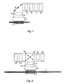
- In
Fig. 1 , rolls being packed are transferred on a conveyor 1. Awrapping station 2 is beside the conveyor 1 and rolls being packed passing on the conveyor are lifted up from the conveyor 1 withcarrier rolls 3 located on both sides of the conveyor and pushed to thewrapping station 2. In this embodiment, immediately beside the wrapping station there is oneplace 4 for the wrapped roll which is set parallel with the travel direction of the conveyor and the roll being packed at thewrapping station 2. In addition to this, there are four additional places 5-8 in the packing machine for different types of wraps. These additional places are located crosswise in relation to the travel direction of the wrap web and, from the wrapped rolls placed in them, the unwrapping direction of the wrap is parallel with the direction of the longitudinal axis of the roll being packed and the transfer direction of the conveyor 1. The wrapped rolls in different roll places can be mutually of different widths or include different types of wraps for forming different packages. In this description, the same reference number refers to both a place for a wrapped roll and a wrapped roll placed in it. - Because the packing wrap has to be fed to the roll being packed at least partially rotating around the longitudinal axis of the roll being packed in the central, overlap and spiral wrapping, the unwrapping direction of the wrap of the wrapped rolls 5-8 being unwrapped from the roll places 5-8 crosswise in relation to the roll being packed is incorrect from the viewpoint of wrapping. For this reason, the travel direction of the wrap has to be changed. Leading a
wrap 21 to the wrappingstation 2 is done by means of a creasing element 9. In this case, the creasing element 9 is located at an angle of 45° in relation to the travel direction of the wrap and the longitudinal axis of the roll being packed. When thewrap 21 rotates around the creasing element 9, its travel direction changes 90°, after which its travel direction is crosswise in relation to the roll being packed and thewrap 21 can be fed to the wrappingstation 2 and wrapped in a conventional way around the roll being packed. The packing wrap and its travel route are shown in the figures only as reference as awide band 21. - As the creasing elements, it is possible to use a rotating creasing roll or a stationary creasing iron which can be a smooth-surfaced, uncovered arrangement or a covered one manufactured of steel or some other material enabling an adequately rigid structure, in which arrangement, there is a surface along which the wrap can slide. For minimising friction, air can be blown between the roll and the wrap or the creasing iron and the wrap or, correspondingly, if the wrap has to be bound against the creasing element, underpressure can be formed between the wrap or the creasing element. To form overpressure or underpressure, holes on the surface of the creasing element can be used or the surface can be porous and air-permeable. All wraps which require changing the wrap direction can be fed via the one and the same creasing element, part of the wrapped rolls can have the same creasing element and part one of their own, or each wrapped roll can have its own creasing element.
- The creasing element 9 could be made transferable in the direction of the longitudinal axis of the roll being packed, whereby e.g. in the overlap and spiral wrapping, the feed point of the wrap for the roll being packed is simply changed by transferring the creasing element. This way, there is no need to transfer the heavy roll being packed or the heavy wrapped roll. Also, the angle of the creasing element can be changed. By changing the angle of the creasing element, it is possible particularly in the spiral wrapping to manage the climbing of the wrap spiral and to control the wrap during wrapping. Similarly, if wrapped rolls are set at different angles in relation to the longitudinal axis of the roll being packed, e.g. in a semi-circle around the wrapping station, it is possible to control with the rotatable creasing elements the wrap coming from each roll in turn to the roll being packed. If required, it is possible to use only one creasing element or a common creasing element for a few wrap webs.
- By arranging several creasing elements successively in the travel path, different wrap feeding webs are provided, whereby the wrapped rolls can be placed in desired positions around the wrapping station according to where there is space for them. It should be noted that the wrapped rolls can be placed in different positions also in the vertical direction, whereby the space above the conveyor 1 can be used for the wrapped rolls. If the axis of the wrapped roll is placed parallel with the travel direction of the conveyor 1 and the axis of the roll being packed at the wrapping station, the wrap can be led to the wrapping station with two 90° creases according to
Fig. 1 . If the wrapped rolls are parallel to the ones inFig. 1 , only one crease is required in principle, but additionally are required guide rolls for bringing the wrap as a desired web to the wrapping station at correct height. -
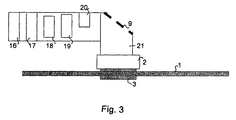
Fig. 2 shows an alternative arrangement in which there are wrapped rolls crosswise in relation to the roll being packed on both sides of the wrappingstation 2, in this case, twoplaces station 2 in the arrangement. For the wraps coming from both sides of the wrappingstation 2, there are theirown creasing elements station 2, a rotatable creasing element reversing the travel direction is not certainly required for the wrapped roll parallel with the conveyors 1. - In the arrangement of
Fig. 3 , roll places 16-20 are arranged in the opposite direction in relation to the travel direction of the conveyor than inFig. 1 . The figure also shows that in the roll places there can be different wrapped rolls, i.e. in theplaces places places - The wrapped rolls can be placed by means of the invention on both sides of the packing line. The best location way and the structure of the packing line are however finally determined always case-specifically according to available space, required packing capacity and equivalent issues.
- An issue to be considered when implementing the invention is the asymmetry of the packing wraps i.e. the different sides of the packing wraps are almost always different of their printing and materials. The packing wrap has to be always wrapped on the roll being packed so that the side coming against the roll actually comes against the roll and the outer side stays outside. If the travel direction of the roll is reversed once in a way described above, its side is changed. This has to be considered when planning the travel path of the packing wrap. Therefore, if there is an odd number of creases, one creasing element has to be added in order to obtain the wrap on the roll being packed the correct side up. This creasing element can be located close to the unwrapping point of the wrapped roll. Then, also the direction of rotation of the roll has to be adapted accurate.
- In principle, it could be possible to use wrapped rolls which have been wrapped oppositely, but as the wrap manufacturing machines are designed to manufacture a product wrapped in a certain way, changing the sides of wrapping in the manufacturing stage of the wrap can be difficult.
- The described embodiments show arrangements in which a roll being packed is transferred in the direction of its longitudinal axis. The invention can be equally applied in packing systems in which the roll is transferred by rolling or by moving crosswise in relation to the packing line.
- It is evident based on the above-described examples that it is possible to implement numerous arrangements different from the above embodiments within the scope of the invention. Thus, the purpose is not to limit the invention to relate only to the above-described examples, but the patent protection should be considered in the full extent of the enclosed claims.
- A method and arrangement for leading the wrap of wrapped rolls in a packing machine from a wrapped roll to a roll being packed in the packing of paper, board and other fibrous rolls comprises at least a wrapping station (2) and at least one place (4) for the wrapped roll. For handling the wrap, the arrangement includes elements (9) for leading a packing wrap (21) from a wrapped roll (4, 5-8) to a roll being packed at the wrapping station (2). Furthermore in the arrangement, there is at least one place (5-8) for the wrapped roll which is located so that the longitudinal axis of the wrapped roll (5-8) placed in it forms an angle with the longitudinal axis of the roll being packed when unwrapping the wrap (21). For leading the wrap (21) to the roll being packed, there is arranged at least one creasing element (9).
Claims (15)
- A method for leading a packing wrap (21) from a wrapped roll (5-8) to a roll being packed at a wrapping station (2), characterised by placing at least one of the wrapped rolls (5-8) of the packing machine so that its longitudinal axis forms an angle with the longitudinal axis of the roll being packed when unwrapping the wrap (21) and that the wrap (21) is led to the roll being packed via at least one creasing element (9).
- A method according to claim 1, characterised by arranging at least part of the wrapped rolls (5-8) at a straight angle in relation to the direction of the longitudinal axis of the roll being packed and by arranging as the travel direction of the wrap (21) of the rolls the travel direction of the roll being packed.
- A method according to claim 1 or 2, characterised by arranging at least part of the wrapped rolls (16-20) at a straight angle in relation to the direction of the longitudinal axis of the roll being packed and by arranging as the travel direction of the wrap (21) of the rolls the opposite direction in relation to the travel direction of the roll being packed and/or by arranging at least part of the wrapped rolls (5-8) at a straight angle in relation to the direction of the longitudinal axis of the roll being packed and by arranging as the travel direction of the wrap (21) of the rolls the travel direction of the roll being packed.
- A method according to any one of claims 1-3, characterised by arranging wrapped rolls at several different angles in relation to the longitudinal axis of the roll being packed.
- A method according to any one of claims 1-4, characterised in that at least one wrapped roll is placed above a conveyor (1) of the roll being packed.
- A method according to any one of claims 1-5, characterised by changing the angle of the creasing element (9) in relation to the longitudinal axis of the roll being packed in connection with packing and/or by changing the position of the creasing element (9) in relation to the roll being packed in the direction of its longitudinal axis.
- A method according to any one of claims 1-6, characterised by changing the direction of the wrap (21) with the creasing elements (9) at least twice before bringing it to the wrapping station (2).
- An arrangement in a packing machine, which comprises at least a wrapping station (2), at least one place (4) for a wrapped roll and elements (9) for leading a packing wrap (21) from a wrapped roll (4, 5-8) to a roll being packed at the wrapping station (2), characterised- of at least one place (5-8) for the wrapped roll which is located so that the longitudinal axis of the wrapped roll (5-8) placed in it forms an angle with the longitudinal axis of the roll being packed when unwrapping the wrap (21) and- of elements for leading the wrap (21) to the roll being packed via at least one creasing element (9).
- An arrangement according to claim 8, characterised in that at least part of the places (5-8) for wrapped rolls are arranged so that the longitudinal axis of the wrapped roll (5-8) fitted in them sets at a straight angle in relation to the direction of the longitudinal axis of the roll being packed and as the travel direction of the wrap (21) of the rolls is arranged the travel direction of the roll being packed.
- An arrangement according to claim 8 or 9, characterised in that at least part of the places (16-20) for wrapped rolls are arranged so that the longitudinal axis of the wrapped roll (16-20) fitted in them sets at a straight angle in relation to the direction of the longitudinal axis of the roll being packed and as the travel direction of the wrap (21) of the rolls is arranged the opposite direction in relation to the travel direction of the roll being packed.
- An arrangement according to any one of claims 8-10, characterised in that at least part of the places (16-20) for wrapped rolls are arranged at a straight angle in relation to the direction of the longitudinal axis of the roll being packed and as the travel direction of the wrap (21) of the rolls is arranged the opposite direction in relation to the travel direction of the roll being packed and at least part of the places (5-8) for wrapped rolls are arranged at a straight angle in relation to the direction of the longitudinal axis of the roll being packed and as the travel direction of the wrap (21) of the rolls is arranged the travel direction of the roll being packed.
- An arrangement according to any one of claims 8-11, characterised in that places for wrapped rolls are arranged at several different angles in relation to the longitudinal axis of the roll being packed.
- An arrangement according to any one of claims 8-12, characterised in that at least one wrapped roll is placed above a conveyor (1) of the roll being packed.
- An arrangement according to any one of claims 8-13, characterised in that the angle of the creasing element (9) can be changed in relation to the longitudinal axis of the roll being packed in connection with packing and/or the position of the creasing element (9) can be changed in relation to the roll being packed in the direction of its longitudinal axis.
- An arrangement according to any one of claims 8-14, characterised of at least two creasing elements for changing the direction of the wrap (21) with the creasing elements (9) at least twice before bringing it to the wrapping station (2).
Applications Claiming Priority (1)
| Application Number | Priority Date | Filing Date | Title |
|---|---|---|---|
| FI20075957A FI124254B (en) | 2007-12-21 | 2007-12-21 | Method and arrangement for placing wrapping rolls and for controlling the wrapping in the roll wrapping |
Publications (2)
| Publication Number | Publication Date |
|---|---|
| EP2077233A1 true EP2077233A1 (en) | 2009-07-08 |
| EP2077233B1 EP2077233B1 (en) | 2011-02-09 |
Family
ID=38951652
Family Applications (1)
| Application Number | Title | Priority Date | Filing Date |
|---|---|---|---|
| EP08170684A Not-in-force EP2077233B1 (en) | 2007-12-21 | 2008-12-04 | Method and arrangement for placing rolls of wrapping material and for leading the wrapping material in a roll packing machine |
Country Status (5)
| Country | Link |
|---|---|
| EP (1) | EP2077233B1 (en) |
| CN (1) | CN101486390B (en) |
| AT (1) | ATE497912T1 (en) |
| DE (1) | DE602008004877D1 (en) |
| FI (1) | FI124254B (en) |
Cited By (1)
| Publication number | Priority date | Publication date | Assignee | Title |
|---|---|---|---|---|
| WO2020125981A1 (en) * | 2018-12-19 | 2020-06-25 | Cyborgline Sa | Pasta packaging machine with rotated reel assembly |
Citations (3)
| Publication number | Priority date | Publication date | Assignee | Title |
|---|---|---|---|---|
| US4448010A (en) | 1981-12-14 | 1984-05-15 | Anderson Bros. Mfg. Co. | Method and apparatus for making bag-type packages |
| DE19530257A1 (en) | 1995-08-17 | 1997-02-20 | Voith Sulzer Finishing Gmbh | Device and method for packaging a roll of material web |
| US6044615A (en) | 1997-04-09 | 2000-04-04 | Ishida Co., Ltd. | Device for supplying film to packaging machine |
-
2007
- 2007-12-21 FI FI20075957A patent/FI124254B/en not_active IP Right Cessation
-
2008
- 2008-12-04 DE DE602008004877T patent/DE602008004877D1/en active Active
- 2008-12-04 EP EP08170684A patent/EP2077233B1/en not_active Not-in-force
- 2008-12-04 AT AT08170684T patent/ATE497912T1/en not_active IP Right Cessation
- 2008-12-22 CN CN2008101853523A patent/CN101486390B/en not_active Expired - Fee Related
Patent Citations (3)
| Publication number | Priority date | Publication date | Assignee | Title |
|---|---|---|---|---|
| US4448010A (en) | 1981-12-14 | 1984-05-15 | Anderson Bros. Mfg. Co. | Method and apparatus for making bag-type packages |
| DE19530257A1 (en) | 1995-08-17 | 1997-02-20 | Voith Sulzer Finishing Gmbh | Device and method for packaging a roll of material web |
| US6044615A (en) | 1997-04-09 | 2000-04-04 | Ishida Co., Ltd. | Device for supplying film to packaging machine |
Cited By (1)
| Publication number | Priority date | Publication date | Assignee | Title |
|---|---|---|---|---|
| WO2020125981A1 (en) * | 2018-12-19 | 2020-06-25 | Cyborgline Sa | Pasta packaging machine with rotated reel assembly |
Also Published As
| Publication number | Publication date |
|---|---|
| FI124254B (en) | 2014-05-15 |
| CN101486390A (en) | 2009-07-22 |
| FI20075957L (en) | 2009-09-02 |
| DE602008004877D1 (en) | 2011-03-24 |
| EP2077233B1 (en) | 2011-02-09 |
| CN101486390B (en) | 2012-03-28 |
| FI20075957A0 (en) | 2007-12-21 |
| ATE497912T1 (en) | 2011-02-15 |
Similar Documents
| Publication | Publication Date | Title |
|---|---|---|
| FI81552B (en) | FOERFARANDE OCH ANORDNING FOER ATT HOPSAMLA VIKTA TRYCKARK. | |
| RS58479B1 (en) | Method for manufacturing paper, card, cardboard or corrugated board cuts and device | |
| FI111834B (en) | Method of packing rolls, in particular paper rolls, apparatus for carrying out the method and roll packing | |
| KR101140673B1 (en) | Automatic Cutting and Packing System for Textile | |
| CN104718147B (en) | Suction conveyer for transport plane object | |
| ITFI20010121A1 (en) | STORAGE LUNG FOR ELONGATED PRODUCTS, SUCH AS PIPES OR OTHER | |
| CA2476111A1 (en) | Apparatus for transverse conveyance of reams | |
| JP5605657B2 (en) | Product transport unit | |
| EP2077233B1 (en) | Method and arrangement for placing rolls of wrapping material and for leading the wrapping material in a roll packing machine | |
| US9694926B2 (en) | Method and system for conveying rolled absorbent products | |
| EP1532062B1 (en) | Storage unit for elongated products | |
| US6935091B2 (en) | Method and apparatus for wrapping articles with a packaging sheet | |
| EP2540626A1 (en) | Packer machine for producing packets of cigarettes | |
| GB2044713A (en) | Method of, and Apparatus for, Packaging Rolls | |
| KR20120078090A (en) | Upender for coil packing device | |
| US20060052196A1 (en) | Chain storage unit for products and means to reduce chanin vibrations | |
| KR100970079B1 (en) | Sheet roll loading system and loading method | |
| EP1827986B1 (en) | Method and arrangement for placing reel end shields | |
| EP1254839B1 (en) | Method and apparatus for wrapping articles with a packaging sheet | |
| EP2368802B1 (en) | Method and apparatus for packing paper reels | |
| EP1809538B1 (en) | Method and arrangement for packaging reels | |
| EP4201822B1 (en) | Machine for packaging groups of pouch wrappings | |
| ITMO20090304A1 (en) | PROCEDURE FOR LOADING BANDS AND RELATIVE PLANT | |
| ITBO20130519A1 (en) | EQUIPMENT FOR GROUPING OF PRODUCTS MIXED TO BE PACKED IN CONTAINERS. |
Legal Events
| Date | Code | Title | Description |
|---|---|---|---|
| PUAI | Public reference made under article 153(3) epc to a published international application that has entered the european phase |
Free format text: ORIGINAL CODE: 0009012 |
|
| AK | Designated contracting states |
Kind code of ref document: A1 Designated state(s): AT BE BG CH CY CZ DE DK EE ES FI FR GB GR HR HU IE IS IT LI LT LU LV MC MT NL NO PL PT RO SE SI SK TR |
|
| AX | Request for extension of the european patent |
Extension state: AL BA MK RS |
|
| AKX | Designation fees paid |
Designated state(s): AT BE BG CH CY CZ DE DK EE ES FI FR GB GR HR HU IE IS IT LI LT LU LV MC MT NL NO PL PT RO SE SI SK TR |
|
| 17Q | First examination report despatched |
Effective date: 20100408 |
|
| GRAP | Despatch of communication of intention to grant a patent |
Free format text: ORIGINAL CODE: EPIDOSNIGR1 |
|
| RIN1 | Information on inventor provided before grant (corrected) |
Inventor name: LINDBERG, HARRI |
|
| GRAS | Grant fee paid |
Free format text: ORIGINAL CODE: EPIDOSNIGR3 |
|
| GRAA | (expected) grant |
Free format text: ORIGINAL CODE: 0009210 |
|
| AK | Designated contracting states |
Kind code of ref document: B1 Designated state(s): AT BE BG CH CY CZ DE DK EE ES FI FR GB GR HR HU IE IS IT LI LT LU LV MC MT NL NO PL PT RO SE SI SK TR |
|
| REG | Reference to a national code |
Ref country code: GB Ref legal event code: FG4D |
|
| REG | Reference to a national code |
Ref country code: CH Ref legal event code: EP |
|
| REG | Reference to a national code |
Ref country code: CH Ref legal event code: NV Representative=s name: NOVAGRAAF INTERNATIONAL SA |
|
| REG | Reference to a national code |
Ref country code: IE Ref legal event code: FG4D |
|
| REF | Corresponds to: |
Ref document number: 602008004877 Country of ref document: DE Date of ref document: 20110324 Kind code of ref document: P |
|
| REG | Reference to a national code |
Ref country code: DE Ref legal event code: R096 Ref document number: 602008004877 Country of ref document: DE Effective date: 20110324 |
|
| REG | Reference to a national code |
Ref country code: SE Ref legal event code: TRGR |
|
| REG | Reference to a national code |
Ref country code: CH Ref legal event code: PFA Owner name: METSO PAPER, INC. Free format text: METSO PAPER, INC.#FABIANINKATU 9 A#00130 HELSINKI (FI) -TRANSFER TO- METSO PAPER, INC.#FABIANINKATU 9 A#00130 HELSINKI (FI) |
|
| REG | Reference to a national code |
Ref country code: NL Ref legal event code: VDEP Effective date: 20110209 |
|
| LTIE | Lt: invalidation of european patent or patent extension |
Effective date: 20110209 |
|
| PG25 | Lapsed in a contracting state [announced via postgrant information from national office to epo] |
Ref country code: LV Free format text: LAPSE BECAUSE OF FAILURE TO SUBMIT A TRANSLATION OF THE DESCRIPTION OR TO PAY THE FEE WITHIN THE PRESCRIBED TIME-LIMIT Effective date: 20110209 Ref country code: LT Free format text: LAPSE BECAUSE OF FAILURE TO SUBMIT A TRANSLATION OF THE DESCRIPTION OR TO PAY THE FEE WITHIN THE PRESCRIBED TIME-LIMIT Effective date: 20110209 Ref country code: PT Free format text: LAPSE BECAUSE OF FAILURE TO SUBMIT A TRANSLATION OF THE DESCRIPTION OR TO PAY THE FEE WITHIN THE PRESCRIBED TIME-LIMIT Effective date: 20110609 Ref country code: NO Free format text: LAPSE BECAUSE OF FAILURE TO SUBMIT A TRANSLATION OF THE DESCRIPTION OR TO PAY THE FEE WITHIN THE PRESCRIBED TIME-LIMIT Effective date: 20110509 Ref country code: ES Free format text: LAPSE BECAUSE OF FAILURE TO SUBMIT A TRANSLATION OF THE DESCRIPTION OR TO PAY THE FEE WITHIN THE PRESCRIBED TIME-LIMIT Effective date: 20110520 Ref country code: GR Free format text: LAPSE BECAUSE OF FAILURE TO SUBMIT A TRANSLATION OF THE DESCRIPTION OR TO PAY THE FEE WITHIN THE PRESCRIBED TIME-LIMIT Effective date: 20110510 Ref country code: HR Free format text: LAPSE BECAUSE OF FAILURE TO SUBMIT A TRANSLATION OF THE DESCRIPTION OR TO PAY THE FEE WITHIN THE PRESCRIBED TIME-LIMIT Effective date: 20110209 |
|
| PG25 | Lapsed in a contracting state [announced via postgrant information from national office to epo] |
Ref country code: BE Free format text: LAPSE BECAUSE OF FAILURE TO SUBMIT A TRANSLATION OF THE DESCRIPTION OR TO PAY THE FEE WITHIN THE PRESCRIBED TIME-LIMIT Effective date: 20110209 Ref country code: BG Free format text: LAPSE BECAUSE OF FAILURE TO SUBMIT A TRANSLATION OF THE DESCRIPTION OR TO PAY THE FEE WITHIN THE PRESCRIBED TIME-LIMIT Effective date: 20110509 Ref country code: PL Free format text: LAPSE BECAUSE OF FAILURE TO SUBMIT A TRANSLATION OF THE DESCRIPTION OR TO PAY THE FEE WITHIN THE PRESCRIBED TIME-LIMIT Effective date: 20110209 Ref country code: AT Free format text: LAPSE BECAUSE OF FAILURE TO SUBMIT A TRANSLATION OF THE DESCRIPTION OR TO PAY THE FEE WITHIN THE PRESCRIBED TIME-LIMIT Effective date: 20110209 Ref country code: NL Free format text: LAPSE BECAUSE OF FAILURE TO SUBMIT A TRANSLATION OF THE DESCRIPTION OR TO PAY THE FEE WITHIN THE PRESCRIBED TIME-LIMIT Effective date: 20110209 Ref country code: CY Free format text: LAPSE BECAUSE OF FAILURE TO SUBMIT A TRANSLATION OF THE DESCRIPTION OR TO PAY THE FEE WITHIN THE PRESCRIBED TIME-LIMIT Effective date: 20110209 Ref country code: FI Free format text: LAPSE BECAUSE OF FAILURE TO SUBMIT A TRANSLATION OF THE DESCRIPTION OR TO PAY THE FEE WITHIN THE PRESCRIBED TIME-LIMIT Effective date: 20110209 Ref country code: SI Free format text: LAPSE BECAUSE OF FAILURE TO SUBMIT A TRANSLATION OF THE DESCRIPTION OR TO PAY THE FEE WITHIN THE PRESCRIBED TIME-LIMIT Effective date: 20110209 |
|
| PG25 | Lapsed in a contracting state [announced via postgrant information from national office to epo] |
Ref country code: EE Free format text: LAPSE BECAUSE OF FAILURE TO SUBMIT A TRANSLATION OF THE DESCRIPTION OR TO PAY THE FEE WITHIN THE PRESCRIBED TIME-LIMIT Effective date: 20110209 Ref country code: DK Free format text: LAPSE BECAUSE OF FAILURE TO SUBMIT A TRANSLATION OF THE DESCRIPTION OR TO PAY THE FEE WITHIN THE PRESCRIBED TIME-LIMIT Effective date: 20110209 |
|
| PG25 | Lapsed in a contracting state [announced via postgrant information from national office to epo] |
Ref country code: CZ Free format text: LAPSE BECAUSE OF FAILURE TO SUBMIT A TRANSLATION OF THE DESCRIPTION OR TO PAY THE FEE WITHIN THE PRESCRIBED TIME-LIMIT Effective date: 20110209 Ref country code: SK Free format text: LAPSE BECAUSE OF FAILURE TO SUBMIT A TRANSLATION OF THE DESCRIPTION OR TO PAY THE FEE WITHIN THE PRESCRIBED TIME-LIMIT Effective date: 20110209 Ref country code: RO Free format text: LAPSE BECAUSE OF FAILURE TO SUBMIT A TRANSLATION OF THE DESCRIPTION OR TO PAY THE FEE WITHIN THE PRESCRIBED TIME-LIMIT Effective date: 20110209 |
|
| PLBE | No opposition filed within time limit |
Free format text: ORIGINAL CODE: 0009261 |
|
| STAA | Information on the status of an ep patent application or granted ep patent |
Free format text: STATUS: NO OPPOSITION FILED WITHIN TIME LIMIT |
|
| 26N | No opposition filed |
Effective date: 20111110 |
|
| REG | Reference to a national code |
Ref country code: DE Ref legal event code: R097 Ref document number: 602008004877 Country of ref document: DE Effective date: 20111110 |
|
| PG25 | Lapsed in a contracting state [announced via postgrant information from national office to epo] |
Ref country code: MC Free format text: LAPSE BECAUSE OF NON-PAYMENT OF DUE FEES Effective date: 20111231 |
|
| REG | Reference to a national code |
Ref country code: FR Ref legal event code: ST Effective date: 20120831 |
|
| REG | Reference to a national code |
Ref country code: IE Ref legal event code: MM4A |
|
| PG25 | Lapsed in a contracting state [announced via postgrant information from national office to epo] |
Ref country code: IE Free format text: LAPSE BECAUSE OF NON-PAYMENT OF DUE FEES Effective date: 20111204 |
|
| PG25 | Lapsed in a contracting state [announced via postgrant information from national office to epo] |
Ref country code: MT Free format text: LAPSE BECAUSE OF FAILURE TO SUBMIT A TRANSLATION OF THE DESCRIPTION OR TO PAY THE FEE WITHIN THE PRESCRIBED TIME-LIMIT Effective date: 20110209 |
|
| PG25 | Lapsed in a contracting state [announced via postgrant information from national office to epo] |
Ref country code: FR Free format text: LAPSE BECAUSE OF NON-PAYMENT OF DUE FEES Effective date: 20120102 |
|
| PG25 | Lapsed in a contracting state [announced via postgrant information from national office to epo] |
Ref country code: LU Free format text: LAPSE BECAUSE OF NON-PAYMENT OF DUE FEES Effective date: 20111204 |
|
| PG25 | Lapsed in a contracting state [announced via postgrant information from national office to epo] |
Ref country code: IS Free format text: LAPSE BECAUSE OF FAILURE TO SUBMIT A TRANSLATION OF THE DESCRIPTION OR TO PAY THE FEE WITHIN THE PRESCRIBED TIME-LIMIT Effective date: 20110209 |
|
| GBPC | Gb: european patent ceased through non-payment of renewal fee |
Effective date: 20121204 |
|
| PG25 | Lapsed in a contracting state [announced via postgrant information from national office to epo] |
Ref country code: TR Free format text: LAPSE BECAUSE OF FAILURE TO SUBMIT A TRANSLATION OF THE DESCRIPTION OR TO PAY THE FEE WITHIN THE PRESCRIBED TIME-LIMIT Effective date: 20110209 |
|
| PG25 | Lapsed in a contracting state [announced via postgrant information from national office to epo] |
Ref country code: HU Free format text: LAPSE BECAUSE OF FAILURE TO SUBMIT A TRANSLATION OF THE DESCRIPTION OR TO PAY THE FEE WITHIN THE PRESCRIBED TIME-LIMIT Effective date: 20110209 |
|
| PG25 | Lapsed in a contracting state [announced via postgrant information from national office to epo] |
Ref country code: GB Free format text: LAPSE BECAUSE OF NON-PAYMENT OF DUE FEES Effective date: 20121204 |
|
| PGFP | Annual fee paid to national office [announced via postgrant information from national office to epo] |
Ref country code: DE Payment date: 20141211 Year of fee payment: 7 Ref country code: CH Payment date: 20141219 Year of fee payment: 7 Ref country code: SE Payment date: 20141219 Year of fee payment: 7 |
|
| PGFP | Annual fee paid to national office [announced via postgrant information from national office to epo] |
Ref country code: IT Payment date: 20141219 Year of fee payment: 7 |
|
| REG | Reference to a national code |
Ref country code: DE Ref legal event code: R119 Ref document number: 602008004877 Country of ref document: DE |
|
| REG | Reference to a national code |
Ref country code: CH Ref legal event code: PL |
|
| REG | Reference to a national code |
Ref country code: SE Ref legal event code: EUG |
|
| PG25 | Lapsed in a contracting state [announced via postgrant information from national office to epo] |
Ref country code: SE Free format text: LAPSE BECAUSE OF NON-PAYMENT OF DUE FEES Effective date: 20151205 |
|
| PG25 | Lapsed in a contracting state [announced via postgrant information from national office to epo] |
Ref country code: DE Free format text: LAPSE BECAUSE OF NON-PAYMENT OF DUE FEES Effective date: 20160701 Ref country code: LI Free format text: LAPSE BECAUSE OF NON-PAYMENT OF DUE FEES Effective date: 20151231 Ref country code: CH Free format text: LAPSE BECAUSE OF NON-PAYMENT OF DUE FEES Effective date: 20151231 |
|
| PG25 | Lapsed in a contracting state [announced via postgrant information from national office to epo] |
Ref country code: IT Free format text: LAPSE BECAUSE OF NON-PAYMENT OF DUE FEES Effective date: 20151204 |