EP2077229A2 - Boat propulsion system and method for controlling boat propulsion system - Google Patents
Boat propulsion system and method for controlling boat propulsion system Download PDFInfo
- Publication number
- EP2077229A2 EP2077229A2 EP08022382A EP08022382A EP2077229A2 EP 2077229 A2 EP2077229 A2 EP 2077229A2 EP 08022382 A EP08022382 A EP 08022382A EP 08022382 A EP08022382 A EP 08022382A EP 2077229 A2 EP2077229 A2 EP 2077229A2
- Authority
- EP
- European Patent Office
- Prior art keywords
- thrust
- detection section
- bracket
- propulsion system
- support bar
- Prior art date
- Legal status (The legal status is an assumption and is not a legal conclusion. Google has not performed a legal analysis and makes no representation as to the accuracy of the status listed.)
- Granted
Links
- 238000000034 method Methods 0.000 title claims abstract description 9
- 238000001514 detection method Methods 0.000 claims abstract description 125
- 238000013459 approach Methods 0.000 claims abstract description 15
- 238000006243 chemical reaction Methods 0.000 claims description 31
- 230000007246 mechanism Effects 0.000 description 19
- 238000010586 diagram Methods 0.000 description 5
- 230000007423 decrease Effects 0.000 description 4
- 238000006073 displacement reaction Methods 0.000 description 4
- 230000005540 biological transmission Effects 0.000 description 3
- 238000010276 construction Methods 0.000 description 3
- 230000007935 neutral effect Effects 0.000 description 3
- 230000008859 change Effects 0.000 description 2
- 230000006835 compression Effects 0.000 description 2
- 238000007906 compression Methods 0.000 description 2
- 230000003247 decreasing effect Effects 0.000 description 2
- 230000004044 response Effects 0.000 description 2
- 230000006866 deterioration Effects 0.000 description 1
- 230000004048 modification Effects 0.000 description 1
- 238000012986 modification Methods 0.000 description 1
- 239000013535 sea water Substances 0.000 description 1
Images







Classifications
-
- B—PERFORMING OPERATIONS; TRANSPORTING
- B63—SHIPS OR OTHER WATERBORNE VESSELS; RELATED EQUIPMENT
- B63H—MARINE PROPULSION OR STEERING
- B63H20/00—Outboard propulsion units, e.g. outboard motors or Z-drives; Arrangements thereof on vessels
- B63H20/08—Means enabling movement of the position of the propulsion element, e.g. for trim, tilt or steering; Control of trim or tilt
- B63H20/10—Means enabling trim or tilt, or lifting of the propulsion element when an obstruction is hit; Control of trim or tilt
-
- B—PERFORMING OPERATIONS; TRANSPORTING
- B63—SHIPS OR OTHER WATERBORNE VESSELS; RELATED EQUIPMENT
- B63H—MARINE PROPULSION OR STEERING
- B63H20/00—Outboard propulsion units, e.g. outboard motors or Z-drives; Arrangements thereof on vessels
- B63H20/007—Trolling propulsion units
-
- B—PERFORMING OPERATIONS; TRANSPORTING
- B63—SHIPS OR OTHER WATERBORNE VESSELS; RELATED EQUIPMENT
- B63H—MARINE PROPULSION OR STEERING
- B63H21/00—Use of propulsion power plant or units on vessels
- B63H21/21—Control means for engine or transmission, specially adapted for use on marine vessels
- B63H21/213—Levers or the like for controlling the engine or the transmission, e.g. single hand control levers
-
- B—PERFORMING OPERATIONS; TRANSPORTING
- B63—SHIPS OR OTHER WATERBORNE VESSELS; RELATED EQUIPMENT
- B63H—MARINE PROPULSION OR STEERING
- B63H20/00—Outboard propulsion units, e.g. outboard motors or Z-drives; Arrangements thereof on vessels
- B63H2020/003—Arrangements of two, or more outboard propulsion units
Definitions
- the present invention relates to a boat propulsion system and a method for controlling a boat propulsion system.
- an output of the boat propulsion system is generally controlled based on a rotational speed of an engine or a propeller.
- the output of the boat propulsion system is generally controlled in such a manner that the rotational speed of the engine or the propeller follows the rotational speed corresponding to an operating amount of a control lever controlled by an operator.
- a boat propulsion system comprising: a control lever by which an accelerator opening can be controlled by an operator; an accelerator opening detection section configured to detect the accelerator opening; a thrust calculation section configured to calculate an intended thrust to be generated from the accelerator opening and configured to output it as calculated thrust; a thrust generating unit configured to generate a thrust; a thrust detection section configured to detect a thrust actually generated by the thrust generating unit and configured to output it as actual thrust; and a control section configured to control an output of the thrust generating unit such that the actual thrust approaches the calculated thrust.
- control section is configured to control the output of the thrust generating unit such that the actual thrust becomes substantially equal to the calculated thrust.
- the thrust detection section is configured to detect forward thrust and/or reverse thrust.
- the boat propulsion system comprises an outboard motor.
- the boat propulsion system further comprises: a mount bracket fixable to a hull, and a swivel bracket swingably supported by the mount bracket in a vertical direction around a swing axis; preferably a propulsion unit mounted on the swivel bracket, the propulsion unit preferably including the thrust generating unit; and preferably a hydraulic cylinder disposed between the mount bracket and the swivel bracket so as to swing the swivel bracket with respect to the mount bracket, wherein the thrust detection section preferably includes a hydraulic pressure detection section configured to detect hydraulic pressure in the hydraulic cylinder, and a thrust conversion section configured to calculate the actual thrust based on the hydraulic pressure detected by the hydraulic pressure detection section.
- the boat propulsion system further comprises: a bracket fixable to a hull, and, preferably, a propulsion unit mounted on the bracket, the propulsion unit preferably including the thrust generating unit, wherein the thrust detection section preferably includes a pressure detection section disposable between the bracket and the hull so as to detect pressure exerted by both the bracket and the hull, and a thrust conversion section configured to calculate the actual thrust based on the pressure detected by the pressure detection section.
- the boat propulsion system further comprises: a bracket fixable to a hull, and an elastic member fixed to the bracket; and preferably a propulsion unit mounted on the bracket via the elastic member, the propulsion unit preferably including the thrust generating unit, wherein the thrust detection section preferably includes a pressure detection section disposed between the bracket and the propulsion unit, and a thrust conversion section configured to calculate the actual thrust based on the pressure detected by the pressure detection section.
- the boat propulsion system further comprises: a hydraulic cylinder disposed between the bracket and the propulsion unit so as to swing the propulsion unit with respect to the bracket; and preferably another elastic member disposed between the hydraulic cylinder and the propulsion unit, wherein the thrust detection section preferably includes a pressure detection section disposed between the propulsion unit and the other elastic member, and a thrust conversion section configured to calculate the actual thrust based on the pressure detected by the pressure detection section.
- the propulsion unit includes a power source configured to generate power, a propeller shaft rotatable by the power generated by the power source, and a propeller attached to the propeller shaft, and, preferably, a pressure detection direction of the pressure detection section generally coincides with an axis direction of the propeller shaft.
- the thrust generating unit includes a propulsion unit configured to convert power generated by the power source into thrust, the propulsion unit including a propeller shaft rotatable by the power generated by the power source and a propeller attached to the propeller shaft, and, preferably, the propulsion unit is fixed to a support bar, and, preferably, a fixing member is configured to support the support bar on a hull.
- the thrust detection section includes a detection section configured to detect a force applied to the support bar, and, preferably, a thrust conversion section configured to calculate the actual thrust based on the force detected by the detection section.
- the detection section is attached to the support bar, and, preferably, includes a strain detection section configured to detect strain of the support bar.
- the support bar includes a first support bar, one end of which is attached to the fixing member, a second support bar, one end of which is attached to the propulsion unit, and a hinge member swingably connecting the other end of the first support bar and the other end of the second support bar, and, preferably, the detection section includes a pressure detection section disposed between the first support bar and the second support bar so as to detect pressure exerted by both the first support bar and the second support bar.
- a boat comprising a boat propulsion system according to one of the above embodiments, and, preferably, a plurality of boat propulsion systems according to one of the above embodiments.
- the aforesaid objective is solved by a method for controlling a boat propulsion system, wherein an accelerator opening, which is controlled by an operator operating a control lever, is detected; an intended thrust to be generated from the accelerator opening is calculated and output as calculated thrust; an actually generated thrust, which is generated by a thrust generating unit, is detected and output as actual thrust; and an output of the thrust generating unit is controlled such that the actual thrust approaches the calculated thrust.
- FIG. 1 is a perspective view of a boat 1 according to a first embodiment as viewed from obliquely rearward.
- FIG. 2 is a schematic side view of an outboard motor 20. As shown in FIG. 1 , the boat 1 includes a hull 10 and the outboard motor 20 as a boat propulsion system.
- the boat 1 is provided with a control lever 12.
- the control lever 12 is operated by an operator for shifting gears and operating an accelerator. Specifically, the operator shifts the control lever 12 into a neutral position to change the shift position to be neutral. Accordingly, driving of a propeller 54 of the outboard motor 20 is stopped.
- the shift position is changed to be forward. Accordingly, a forward thrust is generated in the outboard motor 20.
- the accelerator opening increases as the operating amount of the control lever 12 increases.
- the forward thrust generated in the outboard motor 20 also increases as the accelerator opening increases.
- the outboard motor 20 is mounted at a stern 11 of the hull 10.
- the outboard motor 20 includes an outboard motor body 21 as a propulsion unit, a bracket 22, and a tilt and trim mechanism 30.
- the outboard motor body 21 is fixed to the stern 11 with the bracket 22.
- mounting position of the outboard motor 20 is not limited to the stern 11.
- the outboard motor 20 may be mounted at any part on the hull 10.
- the bracket 22 includes a pair of left and right mount brackets 23 and a swivel bracket 24.
- the mount bracket 23 is fixed to the hull 10 with a screw (not shown).
- the swivel bracket 24 is disposed between the pair of the left and the right mount brackets 23.
- the swivel bracket 24 is supported by the mount brackets 23 via a turning shaft 23a.
- the swivel bracket 24 is swingably supported around the turning shaft 23a in a vertical direction.
- the outboard motor body 21 is attached to the swivel bracket 24 via so called rubber mounts at two locations, an upper mount (not shown) and a lower mount 79, which will be described in detail later.
- the swivel bracket includes a steering bracket 24a and a cylindrical turning shaft sleeve 24b.
- a turning shaft 24c is rotatably inserted in the turning shaft sleeve 24b.
- the steering bracket 24a is fixed to the turning shaft 24c. Accordingly, the turning shaft 24c can be rotated by swinging the steering bracket 24a to the left and right.
- a rear end of the steering bracket 24a is attached to an upper casing 28 of the outboard motor body 21 via a rubber damper (not shown).
- the rubber damper and the rear end of the steering bracket 24a form the upper mount.
- a lower end of the turning shaft 24c is also attached to the upper casing 28 via a damper 24d.
- the damper 24d and the lower end of the turning shaft 24c form the lower mount 79.
- the tilt and trim mechanism 30 is provided on the outboard motor 20.
- the tilt and trim mechanism 30 allows the outboard motor 20 to accomplish a tilt movement and the trim movement.
- the tilt and trim mechanism 30 includes a hydraulic cylinder for tilt 31 and a hydraulic cylinder for trim 32.
- the hydraulic cylinder for tilt 31 relatively largely swings the swivel bracket 24 in the vertical direction around the axis of the turning shaft 23a with respect to the mount bracket 23.
- the hydraulic cylinder for trim 32 relatively slightly swings the swivel bracket 24 in the vertical direction around the axis of the turning shaft 23a with respect to the mount bracket 23.
- the base end of the hydraulic cylinder for tilt 31 is mounted on a rotating shaft 33 fixed to the mount bracket 23 for free rotation.
- the base end of the hydraulic cylinder for trim 32 is also mounted on the rotating shaft 33 fixed to the mount bracket 23 without allowing rotation.
- the hydraulic cylinder for tilt 31 includes, as shown in FIG. 4 , a cylinder body 35 and a piston 37.
- a hydraulic chamber 38 is defined by the cylinder body 35 and the piston 37.
- the base end of a tilt ram 36 is connected to the piston 37.
- a tip of the tilt ram 36 abuts on a sleeve 34 formed on the swivel bracket 24. With the expansion of the hydraulic cylinder for tilt 31, the tilt ram 36 presses upward the sleeve 34.
- the hydraulic cylinder for trim 32 includes a cylinder body 40 and a piston 41.
- a hydraulic chamber 42 is defined by the cylinder body 40 and the piston 41.
- the base end of a trim ram 43 is connected to the piston 41.
- a tip of the trim ram 43 faces the swivel bracket 24.
- An oil temperature sensor 55 is provided in the hydraulic chamber 42.
- the oil temperature sensor 55 detects an oil temperature in the hydraulic chamber 42 as a temperature of oil which circulates in the hydraulic chamber 42 and the hydraulic chamber 38.
- the hydraulic chamber 38 and the hydraulic chamber 42 are respectively connected to an oil pump 45. Pressures in the hydraulic chambers 38, 42 are increased by driving the oil pump 45.
- the piston 37 together with the tilt ram 36 are pushed out upward. Accordingly, the sleeve 34 shown in FIGs. 2 and 3 is pressed upward.
- the swivel bracket 24 together with the outboard motor body 21 rotate around the axis of the turning shaft 23a in an upward direction. In other words, the swivel bracket 24 together with the outboard motor body 21 are tilted up.
- the outboard motor body 21 When the pressure in the hydraulic chamber 42 is increased, the hydraulic cylinder for trim 32 expands. Accordingly, the swivel bracket 24 is pressed obliquely upward toward the rear. As a result, the outboard motor body 21 is adapted to be in a so-called trim-up state. In contrast, when the pressure in the hydraulic chamber 42 is decreased, the hydraulic cylinder for trim 32 contracts. As a result, the outboard motor body 21 is adapted to be in a so-called trim-down state.
- a hydraulic pressure sensor 46 as a hydraulic pressure detection section is provided in the tilt and trim mechanism 30.
- the hydraulic pressure sensor 46 includes a forward thrust measuring hydraulic pressure sensor 47 and a reverse thrust measuring hydraulic pressure sensor 48.
- the forward thrust measuring hydraulic pressure sensor 47 detects hydraulic pressure in the hydraulic chamber 42 in the hydraulic cylinder for trim 32.
- a forward thrust is produced by the propeller 54 shown in FIG. 2 .
- an attractive force is generated between the swivel bracket 24 and the hull 10.
- the hydraulic cylinder for trim 32 receives a force which contracts the hydraulic cylinder for trim 32.
- the pressure in the hydraulic chamber 42 shown in FIG. 4 increases. That is, the pressure in the hydraulic chamber 42 correlates with the forward thrust. Therefore, the forward thrust is calculated from the pressure in the hydraulic chamber 42 detected by the forward thrust measuring hydraulic pressure sensor 47, which will be described in detail later.
- the reverse thrust measuring hydraulic pressure sensor 48 detects hydraulic pressure in the hydraulic chamber 38 in the hydraulic cylinder for tilt 31.
- a reverse thrust is produced by the propeller 54 shown in FIG. 2 .
- a repulsive force is generated in the direction that the outboard motor body 21 separates from the hull 10.
- the hydraulic cylinder for tilt 31 receives a force which expands the hydraulic cylinder for tilt 31.
- the pressure in the hydraulic chamber 38 shown in FIG. 4 decreases. That is, the pressure in the hydraulic chamber 38 correlates with the reverse thrust. Therefore, the reverse thrust is calculated from the pressure in the hydraulic chamber 38 detected by the reverse thrust measuring hydraulic pressure sensor 48, which will be described in detail later.
- FIG. 4 is an oil circuit diagram illustrating connections of the hydraulic cylinder for tilt 31, the hydraulic cylinder for trim 32, and the oil pump 45. Arrangement of the hydraulic cylinder for tilt 31 and the hydraulic cylinder for trim 32 shown in FIG. 4 is a matter of convenience for description. The arrangement of the hydraulic cylinder for tilt 31 and the hydraulic cylinder for trim 32 shown in FIG. 4 is different from the actual arrangement.
- the outboard motor body 21 includes a casing 25 and a thrust generating unit 50.
- the thrust generating unit 50 is housed in the casing 25 except for a part of a propulsion section 57 which will be described later.
- the casing 25 includes an upper cowling 26, a lower cowling 27, an upper casing 28, and a lower casing 29.
- the thrust generating unit 50 generates a thrust.
- the thrust generating unit 50 includes a power source 51, a power transmission mechanism 56, and the propulsion section 57.
- the propulsion section 57 includes a propeller shaft 53 and the propeller 54.
- the propeller 54 is connected to a tip of the propeller shaft 53..
- the power transmission mechanism 56 connects the power source 51 and the propulsion section 57.
- the power transmission mechanism 56 includes a shift mechanism 52.
- the power source 51 generates a turning force as a driving force for the propeller 54.
- the power source 51 is configured by an engine.
- the present teaching does not limit the driving source 51 to the engine.
- the driving source 51 may be an electric motor.
- the shift mechanism 52 converts the turning force generated by the power source 51 into a forward or reverse turning force to transmit to the propeller shaft 53. Or, the shift mechanism 52 disconnects connection between the power source 51 and the propeller shaft 53.
- the shift mechanism 52 provides selection of shift positions between forward, neutral, and reverse.
- the propulsion section 57 converts the turning force of the power source 51 into a thrust.
- the outboard motor 20 includes a control unit 60.
- the control unit 60 is configured by an electronic control unit (ECU).
- ECU electronice control unit
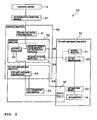
- the control unit 60 includes a thrust calculation section 61, a control section 62, and a thrust conversion section 63.
- the thrust calculation section 61 is connected to an accelerator opening sensor 67 as an accelerator opening detection section.
- the control section 62 includes a subtraction section 64, an output operating amount calculation section 65, and a signal output section 66.
- the thrust calculation section 61 is connected to the subtraction section 64.
- the subtraction section 64 is connected to the output operating amount calculation section 65.
- the output operating amount calculation section 65 is connected to the signal output section 66.
- the signal output section 66 is connected to the power source 51 and the shift mechanism 52.
- the thrust conversion section 63 is connected to the hydraulic pressure sensor 46 and the oil temperature sensor 55. Specifically, the thrust conversion section 63 is connected to the forward thrust measuring hydraulic pressure sensor 47 and the reverse thrust measuring hydraulic pressure sensor 48. The thrust conversion section 63 is also connected to the subtraction section 64. The thrust conversion section 63, together with the hydraulic pressure sensor 46 as a hydraulic pressure detection section and the oil temperature sensor 55, configures a thrust detection section 68.
- the thrust detection section 68 detects a thrust actually generated on the thrust generating unit 50.
- the thrust detection section 68 substantially precisely detects a thrust actually generated on the thrust generating unit 50. More specifically, as will be described later in detail, the thrust detection section 68 detects forces generated between the boat 1 and the outboard motor 20, or between the hull 10 and the outboard motor 20 by the thrust actually generated in the thrust generating unit 50. The thrust detection section 68 further detects forces generated by or changed by the above forces to calculate a thrust actually generated by such detected forces.
- the accelerator opening sensor 67 detects an accelerator opening 70 input by the operator by detecting a position of the control lever 12.
- the accelerator opening sensor 67 outputs the accelerator opening 70 to the thrust calculation section 61.
- the thrust calculation section 61 calculates a thrust to be generated on the thrust generating unit 50 shown in FIG. 5 from the accelerator opening 70.
- the thrust calculation section 61 outputs the calculated thrust as a calculated thrust 71.
- the hydraulic pressure sensor 46 detects the hydraulic pressure in the hydraulic chambers 38, 42 in the hydraulic cylinders 31, 32 shown in FIG. 4 .
- the hydraulic pressure sensor 46 outputs the detected hydraulic pressure as a thrust-correlated force 73 to the thrust conversion section 63.
- the oil temperature sensor 55 detects an oil temperature in the hydraulic chamber 42.
- the oil temperature sensor 55 outputs the detected temperature as an oil temperature 72.
- the thrust conversion section 63 converts the thrust-correlated force 73 into an actual thrust generated on the thrust generating unit 50 shown in FIG.5 .
- the thrust conversion section 63 also compensates the converted thrust with the oil temperature 72.
- the thrust calculation section 63 outputs the compensated thrust as an actual thrust 74.
- the subtraction section 64 subtracts the calculated thrust 71 from the actual thrust 74 to calculate a thrust difference 75.
- the subtraction section 64 outputs the thrust difference 75 to the output operating amount calculation section 65.
- the output operating amount calculation section 65 calculates, from the thrust difference 75, an output operating amount 76 which is required to bring the actual thrust 74 near to the calculated thrust 71. In particular, the output operating amount calculation section 65 calculates the output operating amount 76 which is required to make the actual thrust 74 to be substantially equal to the calculated thrust 71. The output operating amount calculation section 65 outputs the output operating amount 76 to the signal output section 66.
- the signal output section 66 generates an output signal 77 in response to the output operating amount 76.
- the signal output section 66 outputs the output signal 77 to the power source 51.
- the output of the power source 51 is adjusted.
- the obtained thrust may differ for the same operating amount of the control lever.
- the obtained thrust may be different while the accelerator opening is the same. That is, a correlation between the accelerator opening and the actual obtained thrust may be changed by the sea conditions.
- the actual thrust 74 is detected. Then, the output of the thrust generating unit 50 is controlled so that the actual thrust 74 approaches the calculated thrust 71 calculated from the accelerator opening. Therefore, even if the environment surrounding the boat 1 changes, the correlation between the accelerator opening and the actual obtained thrust is resistant to change. That is, it is possible to stabilize the correlation between the accelerator opening and the obtained thrust. In other words, it is possible to stabilize the correlation between the operating amount of the control lever 12 and the obtained thrust.
- the actual thrust 74 is calculated based on the hydraulic pressure detected by the hydraulic pressure sensor 46.
- the hydraulic pressure varies in response to the thrust generated actually.
- the hydraulic pressure correlates with thrust generated actually regardless of the sea conditions. Therefore, it is possible to detect the actual thrust 74 precisely by calculating the actual thrust 74 based on the hydraulic pressure detected by the hydraulic pressure sensor 46.
- the output of the thrust generating unit 50 is controlled in the control section 62 so that the actual thrust 74 is adapted to be substantially equal to the calculated thrust 71.
- the present teaching is not limited to this control.
- the output of the thrust generating unit 50 may be controlled so that the actual thrust 74 approaches the calculated thrust 71 to the extent that the actual thrust 74 is not substantially the same as the calculated thrust 71.
- the forward thrust measuring hydraulic pressure sensor 47 and the reverse thrust measuring hydraulic pressure sensor 48 are separately provided.
- the present teaching is not limited to this structure.
- a single hydraulic pressure sensor for measuring both a forward thrust and a reverse thrust may be provided.
- both the forward thrust measuring hydraulic pressure sensor 47 and the reverse thrust measuring hydraulic pressure sensor 48 may be disposed in either of the hydraulic cylinder for tilt 31 or the hydraulic cylinder for trim 32.
- the forward thrust measuring hydraulic pressure sensor 47 may be disposed in the hydraulic cylinder for tilt 31 while the reverse thrust measuring hydraulic pressure sensor 48 is disposed in the hydraulic cylinder for trim 32.
- a thrust ratio may be calculated by dividing the actual thrust 74 by the calculated thrust 71 in the way that the thrust ratio is controlled to approach one (1).
- the thrust-correlated force 73 is not limited to the hydraulic pressure.
- the thrust-correlated force 73 is not specifically limited as long as it is a force generated between the boat 1 and the outboard motor 20 or between the hull 10 and the outboard motor 20 by the thrust actually generated on the thrust generating unit 50 or as long as it is a force generated or changed by such forces.
- FIGs. 1 , 2 , 4 to 6 are referenced. Components having common functions with the first embodiment will be referenced by common numerals and their description will be omitted.
- FIG. 7 is an enlarged partial sectional view of the mount bracket 23 in this embodiment.
- a pressure sensor 80 is disposed instead of the hydraulic pressure sensor 46.
- the pressure sensor 80 is disposed between the mount bracket 23 and the stern 11.
- a recess 23b is formed on a face 23c of the mount bracket 23, the face 23c facing the stern 11.
- the pressure sensor 80 is disposed in the recess 23b.
- the tip of the pressure sensor 80 protrudes from the face 23c toward the stern 11.
- the mount bracket 23 By fixedly screwing the mount bracket 23 with a screw (not shown), the pressure sensor 80 comes in pressed contact with the stern 11.
- a slight clearance is formed between the face 23c of the mount bracket 23 and the stern 11. Accordingly, for example, when a fore-and-aft force is applied to the mount bracket 23, the mount bracket 23 moves slightly in the fore-and-aft direction with respect to the stern 11.
- pressure between the stern 11 and the mount bracket 23 detected by the pressure sensor 80 is utilized as the thrust-correlated force 73 shown in FIG. 6 .
- the thrust conversion section 63 calculates the actual thrust 74 by utilizing this phenomenon.
- the method utilizing the pressure sensor 80 can easily be applied to an outboard motor not provided with the tilt and trim mechanism 30.
- the pressure sensor 80 is not specifically limited to a certain type as long as it can measure pressure between the stern 11 and the mount bracket 23.
- the pressure sensor 80 may be constituted by a magnetostrictive sensor and the like.
- the pressure sensor 80 is only required to measure pressure when at least one of the stern 11 and the mount bracket 23 generates displacement with respect to the other caused by a force applied to the one of the stern 11 and the mount bracket 23.
- the pressure sensor 80 is not limited to a type that can only measure the pressure when the force is applied to both of the stern 11 and the mount bracket 23.
- the pressure sensor 80 is fixed to the swivel bracket 24 .
- the pressure sensor 80 may be fixed to the stern 11 side.
- FIG. 8 is a sectional view of the lower mount 79 in this embodiment.
- FIG. 8 is the sectional view of the portion taken along the cutout line VIII-VIII in FIG. 2 .
- a damper 24d made up with rubber and the like is fixedly provided in the swivel bracket 24 in the swivel bracket 24, a damper 24d made up with rubber and the like is fixedly provided in the swivel bracket 24.
- the upper casing 28 is fixed to the swivel bracket 24 via the damper 24d as an elastic member. Accordingly, the upper casing 28 is swingable in the fore-and-aft direction with respect to the swivel bracket 24.
- the pressure sensor 82 is disposed between the swivel bracket 24 and the upper casing 28.
- the pressure sensor 82 is mounted on a face of the swivel bracket 24 facing the upper casing 28.
- the pressure sensor 82 is disposed in generally parallel with an axis direction of the propeller shaft 53.
- the pressure sensor 82 is disposed in pressed contact with the upper casing 28 under the condition that no force is applied between the swivel bracket 24 and the upper casing 28.
- a forward thrust is generated on the thrust generating unit 50
- the upper casing 28 is pressed to the swivel bracket 24 side. Accordingly, the pressure detected by the pressure sensor 82 increases.
- a reverse thrust is generated on the thrust generating unit 50
- the upper casing 28 is pulled in a receding direction from the swivel bracket 24. Accordingly, the pressure detected by the pressure sensor 82 decreases.
- the thrust conversion section 63 calculates the actual thrust 74 by utilizing this phenomenon.
- the actual thrust 74 is calculated from the pressure between the swivel bracket 24 and the upper casing 28. At this point, displacement of the upper casing 28 with respect to the swivel bracket 24 is relatively large. As a result, it is relatively easy to precisely measure the pressure between the swivel bracket 24 and the upper casing 28. Therefore, it is possible to detect the actual thrust 74 more precisely.
- the lower mount 79 is made to be a substantially closed space by the swivel bracket 24 and the upper casing 28.
- the pressure sensor 82 is disposed in generally parallel with the axis direction of the propeller shaft 53.
- a direction in which the pressure sensor 82 detects pressure generally coincides with the axis direction of the propeller shaft 53. Therefore, the pressure sensor 82 can detect the thrust more directly. For example, if the pressure detection direction inclines with respect to the axis direction of the propeller shaft 53, the detected pressure needs to be converted into the pressure in the axis direction of the propeller shaft 53. However, in this embodiment as described above, it is not necessary to convert the detected pressure into the pressure in the axis direction of the propeller shaft 53.
- the pressure sensor 82 is only required to measure pressure when at least one of the swivel bracket 24 and the upper casing 28 generates displacement with respect to the other caused by a force applied on the one of the swivel bracket 24 and the upper casing 28.
- the pressure sensor 82 is not limited to a type that can only measure the pressure when the force is applied to both of the swivel bracket 24 and the upper casing 28.
- FIG. 9 is a side view of the tilt and trim mechanism 30 of a fourth embodiment.
- a pressure sensor 83 is provided instead of the hydraulic pressure sensor 46 in the first embodiment.
- the pressure sensor 83 is attached to the swivel bracket 24.
- One end of the pressure sensor 83 is connected to a tip of the trim ram 43 of the hydraulic cylinder for trim 32 via a compression coil spring 84 as another elastic member.
- the pressure detected by the pressure sensor 83 increases.
- the thrust conversion section 63 calculates the actual thrust 74 by utilizing this phenomenon.
- the pressure sensor 83 is only required to measure pressure when at least one of the mount bracket 23 and the swivel bracket 24 generates displacement with respect to the other caused by a force applied to the one of the mount bracket 23 and the swivel bracket 24.
- the pressure sensor 83 is not limited to a type that can only measure the pressure when the force is applied to both of the mount bracket 23 and the swivel bracket 24.
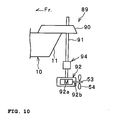
- FIG. 10 is a schematic side view of the rear part of a boat according to a fifth embodiment.
- a boat propulsion system 89 is mounted at the stern 11.
- the boat propulsion system 89 is mounted at the stern 11 in this embodiment.
- mounting position of the boat propulsion system 89 is not limited to the stern 11.
- the boat propulsion system 89 may be mounted at any part on the hull 10.
- the boat propulsion system 89 includes a fixing member 90, a support bar 91, and a thrust generating unit 92.
- the fixing member 90 is fixed to the stern 11. An upper end of the support bar 91 is supported by the fixing member 90. On the other hand, at a lower end of the support bar 91, the thrust generating unit 92 is fixed.
- the thrust generating unit 92 includes an electric motor 92a as a power source and a propulsion section 92b.
- the propulsion section 92b includes the propeller shaft 53 and the propeller 54.
- a detection section 94 is attached to the support bar 91.
- the detection section 94 detects a force applied to the support bar 91.
- the actual thrust 74 is calculated based on the force detected by the detection section 94.
- the support bar 91 includes a first support bar 91a, a second support bar 91 b, and a hinge member 95.
- the first support bar 91 a and the second support bar 91 b are connected to be swingable in the fore-and-aft direction by the hinge member 95.
- a first pressure detection section 96 is disposed between the first support bar 91 a and the second support bar 91 b and in front of the hinge member 95.
- a second pressure detection section 97 is disposed between the first support bar 91 a and the second support bar 91 b and in the rear of the hinge member 95.
- the first pressure detection section 96 and the second pressure detection section 97 may be constituted, for example, by a load cell.
- the thrust conversion section 63 calculates the actual thrust 74 by utilizing this phenomenon.
- an actual generated thrust can also be made closer to a thrust intended to be generated by the operator as in the above first embodiment.
- the high controllability of the outboard motor 20 can be achieved.
- FIG. 12 is a schematic side view showing a construction of a thrust detection section in a variation.
- a force applied to the support bar 91 is detected by the two pressure detection sections 96, 97 is described.
- the teaching is not limited to this structure.
- the force applied to the support bar 91 may be detected by strain detection sections 98, 99 respectively attached to a front and a rear surfaces of the support bar 91.
- the electric motor 92a as a power source is supported at the lower part of the support bar 91 and positioned underwater during operation of the boat is described.
- the electric motor 92a is not limited to be positioned underwater.
- the electric motor 92a may be positioned, for example, on the hull 10.
- the electric motor 92a may be replaced with an engine.
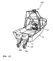
- FIG. 13 is a perspective view from rearward of a boat 100 according to a sixth embodiment.
- FIG. 14 is a control block diagram showing a control system in a sixth embodiment.
- the boat 1 has the single outboard motor 20 is described.
- the teaching is not limited to this structure. The present teaching may be applied to a boat having a plurality of boat propulsion systems.
- the boat 100 includes two outboard motors 20.
- the boat 100 includes an outboard motor 20a, an outboard motor 20b, and a control unit 60.
- the outputs of the thrust generating units 50 are also controlled so that the actual thrust 74 approaches the calculated thrusts 71 for each of the outboard motor 20a and the outboard motor 20b, as in the above first embodiment. This allows an actual generated thrust to be closer to a thrust intended to be generated by the operator. Therefore, it is possible to stabilize the correlation between the operating amount of the control lever 12 and an actual obtained thrust.
- a boat propulsion system comprising: a control lever to which an accelerator opening is input by operation of an operator; an accelerator opening detection section for detecting the input accelerator opening; a thrust calculation section for calculating a thrust intended to be generated from the accelerator opening and outputting it as a calculated thrust; a thrust generating unit for generating a thrust; a thrust detection section for detecting a thrust actually generated on the thrust generating unit to output it as an actual thrust; and a control section for controlling an output of the thrust generating unit so that the actual thrust approaches the calculated thrust.
- control section controls the output of the thrust generating unit so that the actual thrust becomes substantially equal to the calculated thrust.
- the thrust detection section detects both a forward thrust and a reverse thrust.
- the boat propulsion system is an outboard motor.
- the boat propulsion system further comprises: a mount bracket fixed to a hull; a swivel bracket swingably supported by the mount bracket in a vertical direction around a swing axis; a propulsion unit mounted on the swivel bracket, the propulsion unit including the thrust generating unit; and a hydraulic cylinder disposed between the mount bracket and the swivel bracket for swinging the swivel bracket with respect to the mount bracket, wherein the thrust detection section includes a hydraulic pressure detection section for detecting hydraulic pressure in the hydraulic cylinder and a thrust conversion section for calculating the actual thrust based on the hydraulic pressure detected by the hydraulic pressure detection section.
- the boat propulsion system further comprises: a bracket fixed to a hull; and a propulsion unit mounted on the bracket, the propulsion unit including the thrust generating unit, wherein the thrust detection section includes a pressure detection section disposed between the bracket and the hull for detecting pressure exerted by both the bracket and the hull and a thrust conversion section for calculating the actual thrust based on the pressure detected by the pressure detection section.
- the thrust detection section includes a pressure detection section disposed between the bracket and the hull for detecting pressure exerted by both the bracket and the hull and a thrust conversion section for calculating the actual thrust based on the pressure detected by the pressure detection section.
- the boat propulsion system further comprises: a bracket fixed to a hull; an elastic member fixed to the bracket; and a propulsion unit mounted on the bracket via the elastic member, the propulsion unit including the thrust generating unit, wherein the thrust detection section includes a pressure detection section disposed between the bracket and the propulsion unit for detecting pressure exerted by both the bracket and the propulsion unit and a thrust conversion section for calculating the actual thrust based on the pressure detected by the pressure detection section.
- the boat propulsion system further comprises: a bracket fixed to a hull; an elastic member fixed to the bracket; a propulsion unit mounted on the bracket via the elastic member, the propulsion unit including the thrust generating unit; a hydraulic cylinder disposed between the bracket and the propulsion unit for swinging the propulsion unit with respect to the bracket; and another elastic member disposed between the hydraulic cylinder and the propulsion unit, wherein the thrust detection section includes a pressure detection section disposed between the propulsion unit and the other elastic member a thrust conversion section for calculating the actual thrust based on the pressure detected by the pressure detection section.
- the propulsion unit includes a power source for generating a power, a propeller shaft rotated by the power generated on the power source, and a propeller attached to the propeller shaft rotating with the propeller shaft, and a pressure detection direction of the pressure sensor generally coincides with an axis direction of the propeller shaft.
- the thrust generating unit includes a driving source for generating a power and a propulsion section for converting a power generated on the power source into a thrust, the propulsion section including a propeller shaft rotated by the power generated on the power source and a propeller rotating with the propeller shaft, and further comprising: a support bar to which the propulsion section is fixed; and a fixing member for supporting the support bar on the hull.
- the thrust detection section includes a detection section for detecting a force applied to the support bar and a thrust conversion section for calculating the actual thrust based on the force detected by the detection section.
- the detection section is attached to the support bar and includes a strain detection section for detecting strain produced on the support bar.
- the support bar includes a first support bar one end of which is attached to the fixing member, a second support bar one end of which is attached to the propulsion section, and a hinge member for swingably connecting the other end of the first support bar and the other end of the second support bar in the fore-and-aft direction
- the detection section includes a pressure detection section disposed between the first support bar and the second support bar for detecting pressure exerted by both the first support bar and the second support bar.
- a boat comprises the boat propulsion system according to one of the preceding embodiments.
- a plurality of the boat propulsion systems are provided.
- a boat control device including a control lever to which an accelerator opening is input by operation of an operator, an accelerator opening detection section for detecting the input accelerator opening, and a plurality of boat propulsion systems each including a thrust generating unit for generating a thrust and a detection section for detecting a thrust-correlated force actually generated on the thrust generating unit, comprising: a thrust calculation section for calculating a thrust intended to be generated on the boat propulsion system from the accelerator opening and outputting it as a calculated thrust of the boat propulsion system; a thrust conversion section for calculating a thrust actually generated on each boat propulsion system based on the thrust-correlated force and outputting it as an actual thrust of the boat propulsion system; and a control section for controlling an output of the thrust generating unit of each boat propulsion system in each boat propulsion system so that the actual thrust approaches the calculated thrust.
- a boat control device including a control lever, an accelerator opening detection section, and a plurality of boat propulsion systems.
- An accelerator opening is input to the control lever by operation of an operator.
- the accelerator opening detection section detects the input accelerator opening.
- Each boat propulsion system includes a thrust generating unit and a detection section.
- the thrust generating unit generates a thrust.
- the detection section detects a thrust-correlated force actually generated on the thrust generating unit.
- the boat control device includes a thrust calculation section, a thrust conversion section, and a control section.
- the thrust calculation section calculates a thrust intended to be generated on each boat propulsion system from the accelerator opening.
- the thrust calculation section outputs the calculated thrust as a calculated thrust for each boat propulsion system.
- the thrust conversion section calculates a thrust actually generated on each boat propulsion system based on a thrust-correlated force.
- the thrust calculation section outputs the calculated thrust as an actual thrust for each boat propulsion system.
- the control section controls an output of the thrust generating unit of each boat propulsion system so that the actual thrust approaches the calculated thrust.
- a boat control method comprising: a control lever to which an accelerator opening is input by operation of an operator; an accelerator opening detection section for detecting the input accelerator opening; and a plurality of boat propulsion systems each including a thrust generating unit for generating a thrust and a detection section for detecting a thrust-correlated force actually generated on the thrust generating unit, wherein a thrust intended to be generated on each boat propulsion system is calculated from the accelerator opening, an actual thrust actually generated on each boat propulsion system is calculated based on the thrust-correlated force, and an output of the thrust generating unit of each boat propulsion system is controlled in each boat propulsion system so that the actual thrust approaches the calculated thrust.
- an embodiment of a boat propulsion system 20 includes a control lever 12, an accelerator opening detection section 67, a thrust calculation section 61, a thrust generating unit 50, a thrust detection section 68, and a control section 62.
- An accelerator opening 70 is input to the control lever 12 by operation of an operator.
- the accelerator opening detection section 67 detects the input accelerator opening 70.
- the thrust calculation section 61 calculates a thrust intended to be generated from the accelerator opening 70 to output a calculated thrust 71.
- the thrust generating unit 50 generates a thrust.
- the thrust detection section 68 detects a thrust actually generated on the thrust generating unit 50 to output it as an actual thrust 74.
- the control section 62 controls an output of the thrust generating unit 50 so that the actual thrust 74 approaches the calculated thrust 71.
Landscapes
- Chemical & Material Sciences (AREA)
- Engineering & Computer Science (AREA)
- Combustion & Propulsion (AREA)
- Mechanical Engineering (AREA)
- Ocean & Marine Engineering (AREA)
- Fluid-Pressure Circuits (AREA)
- Force Measurement Appropriate To Specific Purposes (AREA)
- Mechanical Control Devices (AREA)
- Transplanting Machines (AREA)
Abstract
Description
- The present invention relates to a boat propulsion system and a method for controlling a boat propulsion system.
- Conventionally, various boat propulsion systems such as an inboard motor, an outboard motor, a so called stern drive etc. are known. As disclosed in
JP-A-Hei 9-104396 - There are some cases that even if the rotational speed of the engine or the propeller is same, an actual thrust obtained by the boat propulsion system differs under different sea conditions. Accordingly, when the rotational speed of the engine or the propeller is controlled to follow the rotational speed corresponding to the operating amount of the control lever, the obtained thrust may differ for the same operating amount of the control lever. The present invention has been made in view of the foregoing problem.
- It is an objective of the invention to stabilize a correlation between the operating amount of the control lever and the obtained thrust.
- According to the present invention, said objective is solved by a boat propulsion system, comprising: a control lever by which an accelerator opening can be controlled by an operator; an accelerator opening detection section configured to detect the accelerator opening; a thrust calculation section configured to calculate an intended thrust to be generated from the accelerator opening and configured to output it as calculated thrust; a thrust generating unit configured to generate a thrust; a thrust detection section configured to detect a thrust actually generated by the thrust generating unit and configured to output it as actual thrust; and a control section configured to control an output of the thrust generating unit such that the actual thrust approaches the calculated thrust.
- Preferably, the control section is configured to control the output of the thrust generating unit such that the actual thrust becomes substantially equal to the calculated thrust.
- Further, preferably the thrust detection section is configured to detect forward thrust and/or reverse thrust.
- Still further, preferably the boat propulsion system comprises an outboard motor.
- According to a preferred embodiment, the boat propulsion system further comprises: a mount bracket fixable to a hull, and a swivel bracket swingably supported by the mount bracket in a vertical direction around a swing axis; preferably a propulsion unit mounted on the swivel bracket, the propulsion unit preferably including the thrust generating unit; and preferably a hydraulic cylinder disposed between the mount bracket and the swivel bracket so as to swing the swivel bracket with respect to the mount bracket, wherein the thrust detection section preferably includes a hydraulic pressure detection section configured to detect hydraulic pressure in the hydraulic cylinder, and a thrust conversion section configured to calculate the actual thrust based on the hydraulic pressure detected by the hydraulic pressure detection section.
- According to another preferred embodiment, the boat propulsion system further comprises: a bracket fixable to a hull, and, preferably, a propulsion unit mounted on the bracket, the propulsion unit preferably including the thrust generating unit, wherein the thrust detection section preferably includes a pressure detection section disposable between the bracket and the hull so as to detect pressure exerted by both the bracket and the hull, and a thrust conversion section configured to calculate the actual thrust based on the pressure detected by the pressure detection section.
- According to yet another preferred embodiment, the boat propulsion system further comprises: a bracket fixable to a hull, and an elastic member fixed to the bracket; and preferably a propulsion unit mounted on the bracket via the elastic member, the propulsion unit preferably including the thrust generating unit, wherein the thrust detection section preferably includes a pressure detection section disposed between the bracket and the propulsion unit, and a thrust conversion section configured to calculate the actual thrust based on the pressure detected by the pressure detection section.
- According to still yet another preferred embodiment, the boat propulsion system further comprises: a hydraulic cylinder disposed between the bracket and the propulsion unit so as to swing the propulsion unit with respect to the bracket; and preferably another elastic member disposed between the hydraulic cylinder and the propulsion unit, wherein the thrust detection section preferably includes a pressure detection section disposed between the propulsion unit and the other elastic member, and a thrust conversion section configured to calculate the actual thrust based on the pressure detected by the pressure detection section.
- Preferably, the propulsion unit includes a power source configured to generate power, a propeller shaft rotatable by the power generated by the power source, and a propeller attached to the propeller shaft, and, preferably, a pressure detection direction of the pressure detection section generally coincides with an axis direction of the propeller shaft.
- Further, preferably the thrust generating unit includes a propulsion unit configured to convert power generated by the power source into thrust, the propulsion unit including a propeller shaft rotatable by the power generated by the power source and a propeller attached to the propeller shaft, and, preferably, the propulsion unit is fixed to a support bar, and, preferably, a fixing member is configured to support the support bar on a hull.
- Still further, preferably the thrust detection section includes a detection section configured to detect a force applied to the support bar, and, preferably, a thrust conversion section configured to calculate the actual thrust based on the force detected by the detection section.
- Yet further still, preferably the detection section is attached to the support bar, and, preferably, includes a strain detection section configured to detect strain of the support bar.
- Preferably, the support bar includes a first support bar, one end of which is attached to the fixing member, a second support bar, one end of which is attached to the propulsion unit, and a hinge member swingably connecting the other end of the first support bar and the other end of the second support bar, and, preferably, the detection section includes a pressure detection section disposed between the first support bar and the second support bar so as to detect pressure exerted by both the first support bar and the second support bar.
- There is further provided a boat comprising a boat propulsion system according to one of the above embodiments, and, preferably, a plurality of boat propulsion systems according to one of the above embodiments.
- According to the present invention, the aforesaid objective is solved by a method for controlling a boat propulsion system, wherein an accelerator opening, which is controlled by an operator operating a control lever, is detected; an intended thrust to be generated from the accelerator opening is calculated and output as calculated thrust; an actually generated thrust, which is generated by a thrust generating unit, is detected and output as actual thrust; and an output of the thrust generating unit is controlled such that the actual thrust approaches the calculated thrust.
- In the following, the present invention is explained in greater detail by means of embodiments thereof in conjunction with the accompanying drawings, wherein:
- FIG. 1
- is a perspective view from rearward of a boat according to a first embodiment;
- FIG. 2
- is a schematic side view of an outboard motor mounted at a stern;
- FIG. 3
- is a side view of a tilt and trim mechanism;
- FIG. 4
- is a conceptual view showing an oil circuit of the tilt and trim mechanism;
- FIG. 5
- is a control block diagram showing a control system in a first embodiment;
- FIG. 6
- is a control block diagram showing control in the first embodiment:
- FIG.7
- is an enlarged partial sectional view of a mount bracket in a second embodiment;
- FIG. 8
- is a sectional view of a lower mount in a third embodiment;
- FIG. 9
- is a side view of a tilt and trim mechanism in a fourth embodiment;
- FIG. 10
- is a schematic side view of the rear part of a boat according to a fifth embodiment;
- Fig. 11
- is a schematic side view showing a construction of a thrust detection section in the fifth embodiment;
- FIG. 12
- is a schematic side view showing a construction of a thrust detection section in a variation;
- FIG. 13
- is a perspective view from rearward of a boat according to a sixth embodiment; and
- FIG. 14
- is a control block diagram showing a control system in the sixth embodiment.
- Among others, the following reference signs are used in the figures:
- 1: boat
- 11: stern
- 12: control lever
- 20: outboard motor (boat propulsion system)
- 21: outboard motor body (propulsion unit)
- 22: bracket
- 23: mount bracket
- 24: swivel bracket
- 24d: damper (elastic member)
- 31: hydraulic cylinder for tilt (hydraulic cylinder)
- 32: hydraulic cylinder for trim (hydraulic cylinder)
- 46: hydraulic pressure sensor (detection section)
- 47: forward thrust measuring hydraulic pressure sensor (hydraulic pressure detection section)
- 48: reverse thrust measuring hydraulic pressure sensor (hydraulic pressure detection section)
- 50: thrust generating unit
- 51: power source
- 53: propeller shaft
- 54: propeller
- 61: thrust calculation section
- 62: control section
- 63: thrust conversion section
- 67: accelerator opening sensor (accelerator opening detection section)
- 68: thrust detection section
- 70: accelerator opening
- 71: calculated thrust
- 73: thrust-correlated force
- 74: actual thrust
- 80: pressure sensor (pressure detection section)
- 82: pressure sensor (pressure detection section)
- 83: pressure sensor (pressure detection section)
- 84: compression coil spring (another elastic member)
- 89: boat propulsion system
- 90: fixing member
- 91: support bar
- 91 a: first support bar
- 91b: second support bar
- 92: thrust generating unit
- 92a: electric motor (power source)
- 92b: propulsion section
- 94: detection section
- 95: hinge member
- 96: first pressure detection section (pressure detection section)
- 97: second pressure detection section (pressure detection section)
- 98, 99: strain detection section
- 100: boat
- Hereinafter, preferred embodiments will be described. However, the present teaching is not limited to the following embodiments.
-
FIG. 1 is a perspective view of aboat 1 according to a first embodiment as viewed from obliquely rearward.FIG. 2 is a schematic side view of anoutboard motor 20. As shown inFIG. 1 , theboat 1 includes ahull 10 and theoutboard motor 20 as a boat propulsion system. - The
boat 1 is provided with acontrol lever 12. Thecontrol lever 12 is operated by an operator for shifting gears and operating an accelerator. Specifically, the operator shifts thecontrol lever 12 into a neutral position to change the shift position to be neutral. Accordingly, driving of apropeller 54 of theoutboard motor 20 is stopped. - When the operator shifts the
control lever 12 into a forward position, the shift position is changed to be forward. Accordingly, a forward thrust is generated in theoutboard motor 20. In the forward position, the accelerator opening increases as the operating amount of thecontrol lever 12 increases. The forward thrust generated in theoutboard motor 20 also increases as the accelerator opening increases. - In contrast, when the operator shifts the
control lever 12 into a reverse position, the shift position is changed to be reverse. Accordingly, a reverse thrust is generated in theoutboard motor 20. In the reverse position, the accelerator opening increases as the operating amount of thecontrol lever 12 increases. The reverse thrust generated in theoutboard motor 20 also increases as the accelerator opening increases. - As shown in
FIGs. 1 and2 , theoutboard motor 20 is mounted at a stern 11 of thehull 10. As shownFIG. 2 , theoutboard motor 20 includes anoutboard motor body 21 as a propulsion unit, abracket 22, and a tilt andtrim mechanism 30. Theoutboard motor body 21 is fixed to the stern 11 with thebracket 22. In this embodiment, an example in which theoutboard motor 20 is mounted at the stern 11 will be described. However, mounting position of theoutboard motor 20 is not limited to the stern 11. Theoutboard motor 20 may be mounted at any part on thehull 10. - The
bracket 22 includes a pair of left andright mount brackets 23 and aswivel bracket 24. Themount bracket 23 is fixed to thehull 10 with a screw (not shown). - The
swivel bracket 24 is disposed between the pair of the left and theright mount brackets 23. Theswivel bracket 24 is supported by themount brackets 23 via a turningshaft 23a. Theswivel bracket 24 is swingably supported around the turningshaft 23a in a vertical direction. Theoutboard motor body 21 is attached to theswivel bracket 24 via so called rubber mounts at two locations, an upper mount (not shown) and alower mount 79, which will be described in detail later. - The swivel bracket includes a
steering bracket 24a and a cylindricalturning shaft sleeve 24b. A turningshaft 24c is rotatably inserted in the turningshaft sleeve 24b. Thesteering bracket 24a is fixed to the turningshaft 24c. Accordingly, the turningshaft 24c can be rotated by swinging thesteering bracket 24a to the left and right. - A rear end of the
steering bracket 24a is attached to anupper casing 28 of theoutboard motor body 21 via a rubber damper (not shown). The rubber damper and the rear end of thesteering bracket 24a form the upper mount. A lower end of the turningshaft 24c is also attached to theupper casing 28 via adamper 24d. Thedamper 24d and the lower end of the turningshaft 24c form thelower mount 79. Thus, theoutboard motor body 21 is swingable with respect to theswivel bracket 24. As a result, a trim movement of theoutboard motor body 21 can be accomplished. - The tilt and
trim mechanism 30 is provided on theoutboard motor 20. The tilt andtrim mechanism 30 allows theoutboard motor 20 to accomplish a tilt movement and the trim movement. Specifically, as shown inFIGs. 2 and3 , the tilt andtrim mechanism 30 includes a hydraulic cylinder fortilt 31 and a hydraulic cylinder fortrim 32. The hydraulic cylinder fortilt 31 relatively largely swings theswivel bracket 24 in the vertical direction around the axis of the turningshaft 23a with respect to themount bracket 23. In contrast, the hydraulic cylinder fortrim 32 relatively slightly swings theswivel bracket 24 in the vertical direction around the axis of the turningshaft 23a with respect to themount bracket 23. - As shown in
FIG. 3 , the base end of the hydraulic cylinder fortilt 31 is mounted on arotating shaft 33 fixed to themount bracket 23 for free rotation. The base end of the hydraulic cylinder fortrim 32 is also mounted on therotating shaft 33 fixed to themount bracket 23 without allowing rotation. - The hydraulic cylinder for
tilt 31 includes, as shown inFIG. 4 , acylinder body 35 and apiston 37. Ahydraulic chamber 38 is defined by thecylinder body 35 and thepiston 37. The base end of atilt ram 36 is connected to thepiston 37. As shown inFIG. 3 , a tip of thetilt ram 36 abuts on asleeve 34 formed on theswivel bracket 24. With the expansion of the hydraulic cylinder fortilt 31, thetilt ram 36 presses upward thesleeve 34. - As shown in
FIG. 4 , the hydraulic cylinder fortrim 32 includes acylinder body 40 and apiston 41. Ahydraulic chamber 42 is defined by thecylinder body 40 and thepiston 41. The base end of atrim ram 43 is connected to thepiston 41. As shown inFIG. 3 , a tip of thetrim ram 43 faces theswivel bracket 24. With the expansion of the hydraulic cylinder fortrim 32, thetrim ram 43 presses obliquely upward theswivel bracket 24 toward the rear. - An
oil temperature sensor 55 is provided in thehydraulic chamber 42. Theoil temperature sensor 55 detects an oil temperature in thehydraulic chamber 42 as a temperature of oil which circulates in thehydraulic chamber 42 and thehydraulic chamber 38. - As shown in
FIG. 4 , thehydraulic chamber 38 and thehydraulic chamber 42 are respectively connected to anoil pump 45. Pressures in thehydraulic chambers oil pump 45. When the pressure in thehydraulic chamber 38 is increased, thepiston 37 together with thetilt ram 36 are pushed out upward. Accordingly, thesleeve 34 shown inFIGs. 2 and3 is pressed upward. As a result, theswivel bracket 24 together with theoutboard motor body 21 rotate around the axis of the turningshaft 23a in an upward direction. In other words, theswivel bracket 24 together with theoutboard motor body 21 are tilted up. - In contrast, when the pressure in the
hydraulic chamber 38 is decreased, the hydraulic cylinder fortilt 31 contracts. As a result, theswivel bracket 24 together with theoutboard motor body 21 rotate around the axis of the turningshaft 23a in a downward direction. In other words, theswivel bracket 24 together with theoutboard motor body 21 are tilted down. - When the pressure in the
hydraulic chamber 42 is increased, the hydraulic cylinder fortrim 32 expands. Accordingly, theswivel bracket 24 is pressed obliquely upward toward the rear. As a result, theoutboard motor body 21 is adapted to be in a so-called trim-up state. In contrast, when the pressure in thehydraulic chamber 42 is decreased, the hydraulic cylinder fortrim 32 contracts. As a result, theoutboard motor body 21 is adapted to be in a so-called trim-down state. - As shown in
FIG. 4 , ahydraulic pressure sensor 46 as a hydraulic pressure detection section is provided in the tilt andtrim mechanism 30. Thehydraulic pressure sensor 46 includes a forward thrust measuringhydraulic pressure sensor 47 and a reverse thrust measuringhydraulic pressure sensor 48. - The forward thrust measuring
hydraulic pressure sensor 47 detects hydraulic pressure in thehydraulic chamber 42 in the hydraulic cylinder fortrim 32. When theboat 1 is running forward, a forward thrust is produced by thepropeller 54 shown inFIG. 2 . Accordingly, an attractive force is generated between theswivel bracket 24 and thehull 10. Thus, the hydraulic cylinder fortrim 32 receives a force which contracts the hydraulic cylinder fortrim 32. As a result, the pressure in thehydraulic chamber 42 shown inFIG. 4 increases. That is, the pressure in thehydraulic chamber 42 correlates with the forward thrust. Therefore, the forward thrust is calculated from the pressure in thehydraulic chamber 42 detected by the forward thrust measuringhydraulic pressure sensor 47, which will be described in detail later. - The reverse thrust measuring
hydraulic pressure sensor 48 detects hydraulic pressure in thehydraulic chamber 38 in the hydraulic cylinder fortilt 31. When theboat 1 is running in reverse, a reverse thrust is produced by thepropeller 54 shown inFIG. 2 . Accordingly, a repulsive force is generated in the direction that theoutboard motor body 21 separates from thehull 10. Thus, the hydraulic cylinder fortilt 31 receives a force which expands the hydraulic cylinder fortilt 31. As a result, the pressure in thehydraulic chamber 38 shown inFIG. 4 decreases. That is, the pressure in thehydraulic chamber 38 correlates with the reverse thrust. Therefore, the reverse thrust is calculated from the pressure in thehydraulic chamber 38 detected by the reverse thrust measuringhydraulic pressure sensor 48, which will be described in detail later. -
FIG. 4 is an oil circuit diagram illustrating connections of the hydraulic cylinder fortilt 31, the hydraulic cylinder fortrim 32, and theoil pump 45. Arrangement of the hydraulic cylinder fortilt 31 and the hydraulic cylinder fortrim 32 shown inFIG. 4 is a matter of convenience for description. The arrangement of the hydraulic cylinder fortilt 31 and the hydraulic cylinder fortrim 32 shown inFIG. 4 is different from the actual arrangement. - As shown in
FIG. 2 , theoutboard motor body 21 includes acasing 25 and athrust generating unit 50. Thethrust generating unit 50 is housed in thecasing 25 except for a part of apropulsion section 57 which will be described later. Thecasing 25 includes anupper cowling 26, alower cowling 27, anupper casing 28, and alower casing 29. - The
thrust generating unit 50 generates a thrust. Thethrust generating unit 50 includes apower source 51, a power transmission mechanism 56, and thepropulsion section 57. Thepropulsion section 57 includes apropeller shaft 53 and thepropeller 54. Thepropeller 54 is connected to a tip of thepropeller shaft 53.. The power transmission mechanism 56 connects thepower source 51 and thepropulsion section 57. The power transmission mechanism 56 includes ashift mechanism 52. - The
power source 51 generates a turning force as a driving force for thepropeller 54. In this embodiment, thepower source 51 is configured by an engine.. However, the present teaching does not limit the drivingsource 51 to the engine. For example, the drivingsource 51 may be an electric motor. - The
shift mechanism 52 converts the turning force generated by thepower source 51 into a forward or reverse turning force to transmit to thepropeller shaft 53. Or, theshift mechanism 52 disconnects connection between thepower source 51 and thepropeller shaft 53. Theshift mechanism 52 provides selection of shift positions between forward, neutral, and reverse. - The
propulsion section 57 converts the turning force of thepower source 51 into a thrust. - Next, mainly referring to
FIGs. 5 and6 , a control block of theboat 1 will be described. - As shown in
FIG. 5 , theoutboard motor 20 includes acontrol unit 60. In this embodiment, thecontrol unit 60 is configured by an electronic control unit (ECU). - The
control unit 60 includes athrust calculation section 61, acontrol section 62, and athrust conversion section 63. Thethrust calculation section 61 is connected to anaccelerator opening sensor 67 as an accelerator opening detection section. Thecontrol section 62 includes asubtraction section 64, an output operatingamount calculation section 65, and asignal output section 66. Thethrust calculation section 61 is connected to thesubtraction section 64. Thesubtraction section 64 is connected to the output operatingamount calculation section 65. The output operatingamount calculation section 65 is connected to thesignal output section 66. Thesignal output section 66 is connected to thepower source 51 and theshift mechanism 52. - The
thrust conversion section 63 is connected to thehydraulic pressure sensor 46 and theoil temperature sensor 55. Specifically, thethrust conversion section 63 is connected to the forward thrust measuringhydraulic pressure sensor 47 and the reverse thrust measuringhydraulic pressure sensor 48. Thethrust conversion section 63 is also connected to thesubtraction section 64. Thethrust conversion section 63, together with thehydraulic pressure sensor 46 as a hydraulic pressure detection section and theoil temperature sensor 55, configures athrust detection section 68. - The
thrust detection section 68 detects a thrust actually generated on thethrust generating unit 50. In particular, thethrust detection section 68 substantially precisely detects a thrust actually generated on thethrust generating unit 50. More specifically, as will be described later in detail, thethrust detection section 68 detects forces generated between theboat 1 and theoutboard motor 20, or between thehull 10 and theoutboard motor 20 by the thrust actually generated in thethrust generating unit 50. Thethrust detection section 68 further detects forces generated by or changed by the above forces to calculate a thrust actually generated by such detected forces. - As shown in
FIG. 6 , theaccelerator opening sensor 67 detects anaccelerator opening 70 input by the operator by detecting a position of thecontrol lever 12. Theaccelerator opening sensor 67 outputs theaccelerator opening 70 to thethrust calculation section 61. - The
thrust calculation section 61 calculates a thrust to be generated on thethrust generating unit 50 shown inFIG. 5 from theaccelerator opening 70. Thethrust calculation section 61 outputs the calculated thrust as acalculated thrust 71. - The
hydraulic pressure sensor 46 detects the hydraulic pressure in thehydraulic chambers hydraulic cylinders FIG. 4 . Thehydraulic pressure sensor 46 outputs the detected hydraulic pressure as a thrust-correlated force 73 to thethrust conversion section 63. - The
oil temperature sensor 55 detects an oil temperature in thehydraulic chamber 42. Theoil temperature sensor 55 outputs the detected temperature as anoil temperature 72. - The
thrust conversion section 63 converts the thrust-correlated force 73 into an actual thrust generated on thethrust generating unit 50 shown inFIG.5 . Thethrust conversion section 63 also compensates the converted thrust with theoil temperature 72. Thethrust calculation section 63 outputs the compensated thrust as anactual thrust 74. - The
subtraction section 64 subtracts the calculated thrust 71 from theactual thrust 74 to calculate athrust difference 75. Thesubtraction section 64 outputs thethrust difference 75 to the output operatingamount calculation section 65. - The output operating
amount calculation section 65 calculates, from thethrust difference 75, anoutput operating amount 76 which is required to bring theactual thrust 74 near to thecalculated thrust 71. In particular, the output operatingamount calculation section 65 calculates theoutput operating amount 76 which is required to make theactual thrust 74 to be substantially equal to thecalculated thrust 71. The output operatingamount calculation section 65 outputs theoutput operating amount 76 to thesignal output section 66. - The
signal output section 66 generates an output signal 77 in response to theoutput operating amount 76. Thesignal output section 66 outputs the output signal 77 to thepower source 51. Thus, the output of thepower source 51 is adjusted. - The above calculations are repeated in the
control unit 60 and, thereby performing the output feedback control on thepower source 51. As a result, theactual thrust 74 approaches thecalculated thrust 71. - As described above, there are some cases that even if the rotational speed of the engine or the propeller is same, actual thrust obtained by the boat propulsion system differs under different sea conditions. Accordingly, when the rotational speed of the engine or the propeller is controlled to follow the rotational speed corresponding to the operating amount of the control lever, the obtained thrust may differ for the same operating amount of the control lever. In other words, the obtained thrust may be different while the accelerator opening is the same. That is, a correlation between the accelerator opening and the actual obtained thrust may be changed by the sea conditions.
- In contrast, in this embodiment, the
actual thrust 74 is detected. Then, the output of thethrust generating unit 50 is controlled so that theactual thrust 74 approaches the calculated thrust 71 calculated from the accelerator opening. Therefore, even if the environment surrounding theboat 1 changes, the correlation between the accelerator opening and the actual obtained thrust is resistant to change. That is, it is possible to stabilize the correlation between the accelerator opening and the obtained thrust. In other words, it is possible to stabilize the correlation between the operating amount of thecontrol lever 12 and the obtained thrust. - In particular, in this embodiment, the
actual thrust 74 is calculated based on the hydraulic pressure detected by thehydraulic pressure sensor 46. The hydraulic pressure varies in response to the thrust generated actually. Thus, the hydraulic pressure correlates with thrust generated actually regardless of the sea conditions. Therefore, it is possible to detect theactual thrust 74 precisely by calculating theactual thrust 74 based on the hydraulic pressure detected by thehydraulic pressure sensor 46. - Further, in this embodiment, since the actual thrust is compensated with the
oil temperature 72, it is possible to detect theactual thrust 74 more precisely. - As in this embodiment, when the
actual thrust 74 is detected by measuring the hydraulic pressure in thehydraulic chambers hydraulic pressure sensor 46 to thehydraulic cylinders outboard motor 20 to apply the present technique. It is relatively easy to equip the existingoutboard motor 20 with thehydraulic pressure sensor 46. Thus, the present technique can be easily applied to the existingoutboard motor 20. - In general, it is preferable that the output of the
thrust generating unit 50 is controlled in thecontrol section 62 so that theactual thrust 74 is adapted to be substantially equal to thecalculated thrust 71. This allows an actual generated thrust to be closer to a thrust intended to be generated by the operator. Therefore, it is possible to further stabilize the correlation between the operating amount of thecontrol lever 12 and an actual obtained thrust. - The present teaching, however, is not limited to this control. Depending on the characteristics of the
boat 1 and theoutboard motor 20, the output of thethrust generating unit 50 may be controlled so that theactual thrust 74 approaches the calculated thrust 71 to the extent that theactual thrust 74 is not substantially the same as thecalculated thrust 71. - In this embodiment, an example in which the forward thrust measuring
hydraulic pressure sensor 47 and the reverse thrust measuringhydraulic pressure sensor 48 are separately provided is described. However, the present teaching is not limited to this structure. For example, a single hydraulic pressure sensor for measuring both a forward thrust and a reverse thrust may be provided. - In this embodiment, an example in which the forward thrust measuring
hydraulic pressure sensor 47 is disposed in the hydraulic cylinder fortrim 32 and the reverse thrust measuringhydraulic pressure sensor 48 is disposed in the hydraulic cylinder fortilt 31 is described. However, the teaching is not limited to this structure. For example, both the forward thrust measuringhydraulic pressure sensor 47 and the reverse thrust measuringhydraulic pressure sensor 48 may be disposed in either of the hydraulic cylinder fortilt 31 or the hydraulic cylinder fortrim 32. Or, the forward thrust measuringhydraulic pressure sensor 47 may be disposed in the hydraulic cylinder fortilt 31 while the reverse thrust measuringhydraulic pressure sensor 48 is disposed in the hydraulic cylinder fortrim 32. - As shown in
FIG. 6 , in this embodiment, an example in which thethrust difference 75 is calculated from theactual thrust 74 and the calculated thrust 71 is described. However, the present teaching is not limited hereto. A thrust ratio may be calculated by dividing theactual thrust 74 by the calculated thrust 71 in the way that the thrust ratio is controlled to approach one (1). - In this embodiment, an example in which hydraulic pressure detected by the
hydraulic pressure sensor 46 is used to calculate theactual thrust 74 is described. However, the present teaching is not limited hereto. In other words, the thrust-correlated force 73 is not limited to the hydraulic pressure. The thrust-correlated force 73 is not specifically limited as long as it is a force generated between theboat 1 and theoutboard motor 20 or between thehull 10 and theoutboard motor 20 by the thrust actually generated on thethrust generating unit 50 or as long as it is a force generated or changed by such forces. - In the following second through fourth embodiments, examples in which the thrust-correlated force 73 is other than hydraulic pressure are described. In the following description,
FIGs. 1 ,2 ,4 to 6 are referenced. Components having common functions with the first embodiment will be referenced by common numerals and their description will be omitted. -
FIG. 7 is an enlarged partial sectional view of themount bracket 23 in this embodiment. In this embodiment, apressure sensor 80 is disposed instead of thehydraulic pressure sensor 46. - The
pressure sensor 80 is disposed between themount bracket 23 and the stern 11. In particular, arecess 23b is formed on aface 23c of themount bracket 23, theface 23c facing the stern 11. Thepressure sensor 80 is disposed in therecess 23b. The tip of thepressure sensor 80 protrudes from theface 23c toward the stern 11. By fixedly screwing themount bracket 23 with a screw (not shown), thepressure sensor 80 comes in pressed contact with the stern 11. A slight clearance is formed between theface 23c of themount bracket 23 and the stern 11. Accordingly, for example, when a fore-and-aft force is applied to themount bracket 23, themount bracket 23 moves slightly in the fore-and-aft direction with respect to the stern 11. - In this embodiment, pressure between the stern 11 and the
mount bracket 23 detected by thepressure sensor 80 is utilized as the thrust-correlated force 73 shown inFIG. 6 . - When a forward thrust is generated on the
thrust generating unit 50, theoutboard motor 20 is pressed to thehull 10 via themount bracket 23. Accordingly, the pressure detected by thepressure sensor 80 increases. In contrast, when a reverse thrust is generated on thethrust generating unit 50, a force is applied on themount bracket 23 in a receding direction from thehull 10. Accordingly, the pressure detected by thepressure sensor 80 decreases. In this embodiment, thethrust conversion section 63 calculates theactual thrust 74 by utilizing this phenomenon. - The method utilizing the
pressure sensor 80 can easily be applied to an outboard motor not provided with the tilt andtrim mechanism 30. - The
pressure sensor 80 is not specifically limited to a certain type as long as it can measure pressure between the stern 11 and themount bracket 23. For example, thepressure sensor 80 may be constituted by a magnetostrictive sensor and the like. - The
pressure sensor 80 is only required to measure pressure when at least one of the stern 11 and themount bracket 23 generates displacement with respect to the other caused by a force applied to the one of the stern 11 and themount bracket 23. Thepressure sensor 80 is not limited to a type that can only measure the pressure when the force is applied to both of the stern 11 and themount bracket 23. - In this embodiment, an example in which the
pressure sensor 80 is fixed to theswivel bracket 24 is described. However, thepressure sensor 80 may be fixed to the stern 11 side. -
FIG. 8 is a sectional view of thelower mount 79 in this embodiment.FIG. 8 is the sectional view of the portion taken along the cutout line VIII-VIII inFIG. 2 . - In this embodiment, an example in which a
pressure sensor 82 is provided instead of thehydraulic pressure sensor 46 in the first embodiment is described. - As shown in
FIG. 8 , in theswivel bracket 24, adamper 24d made up with rubber and the like is fixedly provided. Theupper casing 28 is fixed to theswivel bracket 24 via thedamper 24d as an elastic member. Accordingly, theupper casing 28 is swingable in the fore-and-aft direction with respect to theswivel bracket 24. - The
pressure sensor 82 is disposed between theswivel bracket 24 and theupper casing 28. Thepressure sensor 82 is mounted on a face of theswivel bracket 24 facing theupper casing 28. Thepressure sensor 82 is disposed in generally parallel with an axis direction of thepropeller shaft 53. - The
pressure sensor 82 is disposed in pressed contact with theupper casing 28 under the condition that no force is applied between theswivel bracket 24 and theupper casing 28. When a forward thrust is generated on thethrust generating unit 50, theupper casing 28 is pressed to theswivel bracket 24 side. Accordingly, the pressure detected by thepressure sensor 82 increases. In contrast, when a reverse thrust is generated on thethrust generating unit 50, theupper casing 28 is pulled in a receding direction from theswivel bracket 24. Accordingly, the pressure detected by thepressure sensor 82 decreases. In this embodiment, thethrust conversion section 63 calculates theactual thrust 74 by utilizing this phenomenon. - As described above, in this embodiment, the
actual thrust 74 is calculated from the pressure between theswivel bracket 24 and theupper casing 28. At this point, displacement of theupper casing 28 with respect to theswivel bracket 24 is relatively large. As a result, it is relatively easy to precisely measure the pressure between theswivel bracket 24 and theupper casing 28. Therefore, it is possible to detect theactual thrust 74 more precisely. - The
lower mount 79 is made to be a substantially closed space by theswivel bracket 24 and theupper casing 28. Thus, it is possible to reduce influences from the sea water and the like exerted on thepressure sensor 82 by disposing thepressure sensor 82 in thelower mount 79. Therefore, disturbance in pressure detection of thepressure sensor 82 can be reduced. Also, deterioration of thepressure sensor 82 can be reduced. - In this embodiment, the
pressure sensor 82 is disposed in generally parallel with the axis direction of thepropeller shaft 53. A direction in which thepressure sensor 82 detects pressure generally coincides with the axis direction of thepropeller shaft 53. Therefore, thepressure sensor 82 can detect the thrust more directly. For example, if the pressure detection direction inclines with respect to the axis direction of thepropeller shaft 53, the detected pressure needs to be converted into the pressure in the axis direction of thepropeller shaft 53. However, in this embodiment as described above, it is not necessary to convert the detected pressure into the pressure in the axis direction of thepropeller shaft 53. - The
pressure sensor 82 is only required to measure pressure when at least one of theswivel bracket 24 and theupper casing 28 generates displacement with respect to the other caused by a force applied on the one of theswivel bracket 24 and theupper casing 28. Thepressure sensor 82 is not limited to a type that can only measure the pressure when the force is applied to both of theswivel bracket 24 and theupper casing 28. -
FIG. 9 is a side view of the tilt andtrim mechanism 30 of a fourth embodiment. - In this embodiment, a
pressure sensor 83 is provided instead of thehydraulic pressure sensor 46 in the first embodiment. - As shown in
FIG. 9 , thepressure sensor 83 is attached to theswivel bracket 24. One end of thepressure sensor 83 is connected to a tip of thetrim ram 43 of the hydraulic cylinder fortrim 32 via acompression coil spring 84 as another elastic member. Thus, when the forward thrust is generated on thethrust generating unit 50, theswivel bracket 24 is pressed to themount bracket 23 side. Accordingly, the pressure detected by thepressure sensor 83 increases. In contrast, when a reverse thrust is generated on thethrust generating unit 50, theswivel bracket 24 is pulled in the receding direction from themount bracket 23. Accordingly, the pressure detected by thepressure sensor 83 decreases. In this embodiment, thethrust conversion section 63 calculates theactual thrust 74 by utilizing this phenomenon. - In the case that the actual thrust is detected by the
pressure sensor 83 as in this embodiment, such detection can easily be achieved on an outboard motor having the tilt andtrim mechanism 30 only by adding thepressure sensor 83. - The
pressure sensor 83 is only required to measure pressure when at least one of themount bracket 23 and theswivel bracket 24 generates displacement with respect to the other caused by a force applied to the one of themount bracket 23 and theswivel bracket 24. Thepressure sensor 83 is not limited to a type that can only measure the pressure when the force is applied to both of themount bracket 23 and theswivel bracket 24. - In the above first to fourth embodiments, an example in which an outboard motor is used as a boat propulsion system is described. However, in the present teaching, the boat propulsion system is not limited to the outboard motor.
-
FIG. 10 is a schematic side view of the rear part of a boat according to a fifth embodiment. In this embodiment, aboat propulsion system 89 is mounted at the stern 11. - In this embodiment, an example in which the
boat propulsion system 89 is mounted at the stern 11 will be described. However, mounting position of theboat propulsion system 89 is not limited to the stern 11. Theboat propulsion system 89 may be mounted at any part on thehull 10. - The
boat propulsion system 89 includes a fixingmember 90, asupport bar 91, and athrust generating unit 92. The fixingmember 90 is fixed to the stern 11. An upper end of thesupport bar 91 is supported by the fixingmember 90. On the other hand, at a lower end of thesupport bar 91, thethrust generating unit 92 is fixed. - The
thrust generating unit 92 includes anelectric motor 92a as a power source and apropulsion section 92b. Thepropulsion section 92b includes thepropeller shaft 53 and thepropeller 54. - A
detection section 94 is attached to thesupport bar 91. Thedetection section 94 detects a force applied to thesupport bar 91. In this embodiment, theactual thrust 74 is calculated based on the force detected by thedetection section 94. - In particular, as shown in
FIG. 11 , thesupport bar 91 includes afirst support bar 91a, asecond support bar 91 b, and ahinge member 95. Thefirst support bar 91 a and thesecond support bar 91 b are connected to be swingable in the fore-and-aft direction by thehinge member 95. A firstpressure detection section 96 is disposed between thefirst support bar 91 a and thesecond support bar 91 b and in front of thehinge member 95. In contrast, a secondpressure detection section 97 is disposed between thefirst support bar 91 a and thesecond support bar 91 b and in the rear of thehinge member 95. The firstpressure detection section 96 and the secondpressure detection section 97 may be constituted, for example, by a load cell. - When a forward thrust is generated on the
thrust generating unit 50, a force directed forward is applied to the lower end of thesupport bar 91. Accordingly, the pressure detected by the firstpressure detection section 96 increases. In contrast, when a reverse thrust is generated on thethrust generating unit 92, a force directed rearward is applied to the lower end of thesupport bar 91. Accordingly, the pressure detected by the secondpressure detection section 97 increases. In this embodiment, thethrust conversion section 63 calculates theactual thrust 74 by utilizing this phenomenon. - In this embodiment, an actual generated thrust can also be made closer to a thrust intended to be generated by the operator as in the above first embodiment. Thus, the high controllability of the
outboard motor 20 can be achieved. -
FIG. 12 is a schematic side view showing a construction of a thrust detection section in a variation. In the above fifth embodiment, an example in which a force applied to thesupport bar 91 is detected by the twopressure detection sections FIG. 12 , the force applied to thesupport bar 91 may be detected bystrain detection sections support bar 91. - Further, in the above fifth embodiment, an example in which the
electric motor 92a as a power source is supported at the lower part of thesupport bar 91 and positioned underwater during operation of the boat is described. However, theelectric motor 92a is not limited to be positioned underwater. Theelectric motor 92a may be positioned, for example, on thehull 10. - Further, the
electric motor 92a may be replaced with an engine. -
FIG. 13 is a perspective view from rearward of aboat 100 according to a sixth embodiment.FIG. 14 is a control block diagram showing a control system in a sixth embodiment. In the above first embodiment, an example in which theboat 1 has the singleoutboard motor 20 is described. However, the teaching is not limited to this structure. The present teaching may be applied to a boat having a plurality of boat propulsion systems. - As shown in
FIG. 13 , theboat 100 according to the sixth embodiment includes twooutboard motors 20. In particular, theboat 100 includes anoutboard motor 20a, anoutboard motor 20b, and acontrol unit 60. In this embodiment, the outputs of thethrust generating units 50 are also controlled so that theactual thrust 74 approaches the calculated thrusts 71 for each of theoutboard motor 20a and theoutboard motor 20b, as in the above first embodiment. This allows an actual generated thrust to be closer to a thrust intended to be generated by the operator. Therefore, it is possible to stabilize the correlation between the operating amount of thecontrol lever 12 and an actual obtained thrust. - The description above discloses (among others) an embodiment of a boat propulsion system, comprising: a control lever to which an accelerator opening is input by operation of an operator; an accelerator opening detection section for detecting the input accelerator opening; a thrust calculation section for calculating a thrust intended to be generated from the accelerator opening and outputting it as a calculated thrust; a thrust generating unit for generating a thrust; a thrust detection section for detecting a thrust actually generated on the thrust generating unit to output it as an actual thrust; and a control section for controlling an output of the thrust generating unit so that the actual thrust approaches the calculated thrust.
- Preferably, the control section controls the output of the thrust generating unit so that the actual thrust becomes substantially equal to the calculated thrust.
- Further, preferably the thrust detection section detects both a forward thrust and a reverse thrust.
- Further, preferably the boat propulsion system is an outboard motor.
- Preferably, the boat propulsion system further comprises: a mount bracket fixed to a hull; a swivel bracket swingably supported by the mount bracket in a vertical direction around a swing axis; a propulsion unit mounted on the swivel bracket, the propulsion unit including the thrust generating unit; and a hydraulic cylinder disposed between the mount bracket and the swivel bracket for swinging the swivel bracket with respect to the mount bracket, wherein the thrust detection section includes a hydraulic pressure detection section for detecting hydraulic pressure in the hydraulic cylinder and a thrust conversion section for calculating the actual thrust based on the hydraulic pressure detected by the hydraulic pressure detection section.
- Preferably, the boat propulsion system further comprises: a bracket fixed to a hull; and a propulsion unit mounted on the bracket, the propulsion unit including the thrust generating unit, wherein the thrust detection section includes a pressure detection section disposed between the bracket and the hull for detecting pressure exerted by both the bracket and the hull and a thrust conversion section for calculating the actual thrust based on the pressure detected by the pressure detection section.
- Preferably, the boat propulsion system further comprises: a bracket fixed to a hull; an elastic member fixed to the bracket; and a propulsion unit mounted on the bracket via the elastic member, the propulsion unit including the thrust generating unit, wherein the thrust detection section includes a pressure detection section disposed between the bracket and the propulsion unit for detecting pressure exerted by both the bracket and the propulsion unit and a thrust conversion section for calculating the actual thrust based on the pressure detected by the pressure detection section.
- Preferably, the boat propulsion system further comprises: a bracket fixed to a hull; an elastic member fixed to the bracket; a propulsion unit mounted on the bracket via the elastic member, the propulsion unit including the thrust generating unit; a hydraulic cylinder disposed between the bracket and the propulsion unit for swinging the propulsion unit with respect to the bracket; and another elastic member disposed between the hydraulic cylinder and the propulsion unit, wherein the thrust detection section includes a pressure detection section disposed between the propulsion unit and the other elastic member a thrust conversion section for calculating the actual thrust based on the pressure detected by the pressure detection section.
- Further, preferably the propulsion unit includes a power source for generating a power, a propeller shaft rotated by the power generated on the power source, and a propeller attached to the propeller shaft rotating with the propeller shaft, and a pressure detection direction of the pressure sensor generally coincides with an axis direction of the propeller shaft.
- Further, preferably the thrust generating unit includes a driving source for generating a power and a propulsion section for converting a power generated on the power source into a thrust, the propulsion section including a propeller shaft rotated by the power generated on the power source and a propeller rotating with the propeller shaft, and further comprising: a support bar to which the propulsion section is fixed; and a fixing member for supporting the support bar on the hull.
- Further, preferably the thrust detection section includes a detection section for detecting a force applied to the support bar and a thrust conversion section for calculating the actual thrust based on the force detected by the detection section.
- Further, preferably the detection section is attached to the support bar and includes a strain detection section for detecting strain produced on the support bar.
- Further, preferably the support bar includes a first support bar one end of which is attached to the fixing member, a second support bar one end of which is attached to the propulsion section, and a hinge member for swingably connecting the other end of the first support bar and the other end of the second support bar in the fore-and-aft direction, and the detection section includes a pressure detection section disposed between the first support bar and the second support bar for detecting pressure exerted by both the first support bar and the second support bar.
- Preferably, a boat comprises the boat propulsion system according to one of the preceding embodiments.
- Further, preferably a plurality of the boat propulsion systems are provided.
- The description above also discloses an embodiment of a boat control device including a control lever to which an accelerator opening is input by operation of an operator, an accelerator opening detection section for detecting the input accelerator opening, and a plurality of boat propulsion systems each including a thrust generating unit for generating a thrust and a detection section for detecting a thrust-correlated force actually generated on the thrust generating unit, comprising: a thrust calculation section for calculating a thrust intended to be generated on the boat propulsion system from the accelerator opening and outputting it as a calculated thrust of the boat propulsion system; a thrust conversion section for calculating a thrust actually generated on each boat propulsion system based on the thrust-correlated force and outputting it as an actual thrust of the boat propulsion system; and a control section for controlling an output of the thrust generating unit of each boat propulsion system in each boat propulsion system so that the actual thrust approaches the calculated thrust.
- The description above also discloses an embodiment of a boat control device including a control lever, an accelerator opening detection section, and a plurality of boat propulsion systems. An accelerator opening is input to the control lever by operation of an operator. The accelerator opening detection section detects the input accelerator opening. Each boat propulsion system includes a thrust generating unit and a detection section. The thrust generating unit generates a thrust. The detection section detects a thrust-correlated force actually generated on the thrust generating unit. The boat control device includes a thrust calculation section, a thrust conversion section, and a control section. The thrust calculation section calculates a thrust intended to be generated on each boat propulsion system from the accelerator opening. The thrust calculation section outputs the calculated thrust as a calculated thrust for each boat propulsion system. The thrust conversion section calculates a thrust actually generated on each boat propulsion system based on a thrust-correlated force. The thrust calculation section outputs the calculated thrust as an actual thrust for each boat propulsion system. In each boat propulsion system, the control section controls an output of the thrust generating unit of each boat propulsion system so that the actual thrust approaches the calculated thrust.
- Moreover, the description above discloses an embodiment of a boat control method comprising: a control lever to which an accelerator opening is input by operation of an operator; an accelerator opening detection section for detecting the input accelerator opening; and a plurality of boat propulsion systems each including a thrust generating unit for generating a thrust and a detection section for detecting a thrust-correlated force actually generated on the thrust generating unit, wherein a thrust intended to be generated on each boat propulsion system is calculated from the accelerator opening, an actual thrust actually generated on each boat propulsion system is calculated based on the thrust-correlated force, and an output of the thrust generating unit of each boat propulsion system is controlled in each boat propulsion system so that the actual thrust approaches the calculated thrust.
- In order to stabilize a correlation between an operating amount of a control lever and an obtained thrust, an embodiment of a
boat propulsion system 20 includes acontrol lever 12, an acceleratoropening detection section 67, athrust calculation section 61, athrust generating unit 50, athrust detection section 68, and acontrol section 62. Anaccelerator opening 70 is input to thecontrol lever 12 by operation of an operator. The acceleratoropening detection section 67 detects theinput accelerator opening 70. Thethrust calculation section 61 calculates a thrust intended to be generated from theaccelerator opening 70 to output acalculated thrust 71. Thethrust generating unit 50 generates a thrust. Thethrust detection section 68 detects a thrust actually generated on thethrust generating unit 50 to output it as anactual thrust 74. Thecontrol section 62 controls an output of thethrust generating unit 50 so that theactual thrust 74 approaches thecalculated thrust 71.
Claims (15)
- Boat propulsion system, comprising:a control lever (12) by which an accelerator opening can be controlled by an operator;an accelerator opening detection section (67) configured to detect the accelerator opening;a thrust calculation section (61) configured to calculate an intended thrust to be generated from the accelerator opening and configured to output it as calculated thrust;a thrust generating unit (50) configured to generate a thrust;a thrust detection section (68) configured to detect a thrust actually generated by the thrust generating unit and configured to output it as actual thrust; anda control section (62) configured to control an output of the thrust generating unit (50) such that the actual thrust approaches the calculated thrust.
- Boat propulsion system according to claim 1, wherein the control section (62) is configured to control the output of the thrust generating unit (50) such that the actual thrust becomes substantially equal to the calculated thrust.
- Boat propulsion system according to claim 1 or 2, wherein the thrust detection section (68) is configured to detect forward thrust and/or reverse thrust.
- Boat propulsion system according to one of claims 1 to 3, wherein the boat propulsion system comprises an outboard motor (20).
- Boat propulsion system according to one of claims 1 to 4, further comprising:a mount bracket (23) fixable to a hull (10), and a swivel bracket (24) swingably supported by the mount bracket (23) in a vertical direction around a swing axis;preferably a propulsion unit (21) mounted on the swivel bracket (24), the propulsion unit (21) preferably including the thrust generating unit (50); andpreferably a hydraulic cylinder (31,32) disposed between the mount bracket (23) and the swivel bracket (24) so as to swing the swivel bracket (24) with respect to the mount bracket (23), wherein the thrust detection section (68) preferably includes a hydraulic pressure detection section (46,47) configured to detect hydraulic pressure in the hydraulic cylinder (31,32), and a thrust conversion section (63) configured to calculate the actual thrust based on the hydraulic pressure detected by the hydraulic pressure detection section (46,47).
- Boat propulsion system according to one of claims 1 to 4, further comprising:a bracket (22) fixable to a hull (10), and, preferably, a propulsion unit (21) mounted on the bracket (22), the propulsion unit (21) preferably including the thrust generating unit (50), wherein the thrust detection section (68) preferably includes a pressure detection section (80) disposable between the bracket (22) and the hull (10) so as to detect pressure exerted by both the bracket (22) andthe hull (10), and a thrust conversion section (63) configured to calculate the actual thrust based on the pressure detected by the pressure detection section (80).
- Boat propulsion system according to one of claims 1 to 4, further comprising:a bracket (22) fixable to a hull (10), and an elastic member (24d) fixed to the bracket (22); andpreferably a propulsion unit (21) mounted on the bracket (22) via the elastic member (24d), the propulsion unit (21) preferably including the thrust generating unit (50), wherein the thrust detection section (68) preferably includes a pressure detection section (82,83) disposed between the bracket (22) and the propulsion unit (21), and a thrust conversion section (63) configured to calculate the actual thrust based on the pressure detected by the pressure detection section (82,83).
- Boat propulsion system according to claim 7, further comprising:a hydraulic cylinder (31,32) disposed between the bracket (22) and the propulsion unit (21) so as to swing the propulsion unit (21) with respect to the bracket (22); andpreferably another elastic member (84) disposed between the hydraulic cylinder (31,32) and the propulsion unit (21), wherein the thrust detection section (68) preferably includes a pressure detection section (83) disposed between the propulsion unit (21) and the other elastic member (84), and a thrust conversion section (63) configured to calculate the actual thrust based on the pressure detected by the pressure detection section (83).
- Boat propulsion system according to one of claims 5 to 8, wherein the propulsion unit (21) includes a power source (51) configured to generate power, a propeller shaft (53) rotatable by the power generated by the power source (51), and a propeller (54) attached to the propeller shaft (53), and, preferably, a pressure detection direction of the pressure detection section (46,47,80,82,83) generally coincides with an axis direction of the propeller shaft (53).
- Boat propulsion system according to one of claims 1 to 9, wherein the thrust generating unit (50) includes a propulsion unit (21) configured to convert power generated by the power source (51) into thrust, the propulsion unit (21) including a propeller shaft (53) rotatable by the power generated by the power source (51) and a propeller (54) attached to the propeller shaft (53), and, preferably, the propulsion unit (21) is fixed to a support bar (91), and, preferably, a fixing member (90) is configured to support the support bar (91) on a hull (10).
- Boat propulsion system according to claim 10, wherein the thrust detection section (68) includes a detection section (94) configured to detect a force applied to the support bar (91), and, preferably, a thrust conversion section (63) configured to calculate the actual thrust based on the force detected by the detection section (68).
- Boat propulsion system according to claim 11, wherein the detection section (68) is attached to the support bar (91), and, preferably, includes a strain detection section configured to detect strain of the support bar (91).
- Boat propulsion system according to claim 12, wherein the support bar (91) includes a first support bar (91 a), one end of which is attached to the fixing member (90), a second support bar (91 b), one end of which is attached to the propulsion unit (21), and a hinge member (95) swingably connecting the other end of the first support bar (91 a) and the other end of the second support bar (91 b), and, preferably, the detection section (94) includes a pressure detection section (96,97) disposed between the first support bar (91a) and the second support bar (91 b) so as to detect pressure exerted by both the first support bar (91 a) and the second support bar (91 b).
- Boat comprising a boat propulsion system according to one of claims 1 to 13, and, preferably, a plurality of boat propulsion systems according to one of claims 1 to 13.
- Method for controlling a boat propulsion system, wherein
an accelerator opening, which is controlled by an operator operating a control lever (12), is detected;
an intended thrust to be generated from the accelerator opening is calculated and output as calculated thrust;
an actually generated thrust, which is generated by a thrust generating unit (50), is detected and output as actual thrust; and
an output of the thrust generating unit (50) is controlled such that the actual thrust approaches the calculated thrust.
Applications Claiming Priority (1)
| Application Number | Priority Date | Filing Date | Title |
|---|---|---|---|
| JP2007337197A JP5228199B2 (en) | 2007-12-27 | 2007-12-27 | Ship propulsion system, ship provided with the same, ship control apparatus and control method |
Publications (3)
| Publication Number | Publication Date |
|---|---|
| EP2077229A2 true EP2077229A2 (en) | 2009-07-08 |
| EP2077229A3 EP2077229A3 (en) | 2017-05-31 |
| EP2077229B1 EP2077229B1 (en) | 2019-05-08 |
Family
ID=40547849
Family Applications (1)
| Application Number | Title | Priority Date | Filing Date |
|---|---|---|---|
| EP08022382.9A Not-in-force EP2077229B1 (en) | 2007-12-27 | 2008-12-23 | Boat propulsion system and method for controlling boat propulsion system |
Country Status (3)
| Country | Link |
|---|---|
| US (1) | US7959479B2 (en) |
| EP (1) | EP2077229B1 (en) |
| JP (1) | JP5228199B2 (en) |
Cited By (1)
| Publication number | Priority date | Publication date | Assignee | Title |
|---|---|---|---|---|
| EP2865591B1 (en) * | 2012-06-25 | 2018-08-08 | Suzuki Motor Corporation | Shift control device of outboard motor, and shift control method and program of outboard motor |
Families Citing this family (4)
| Publication number | Priority date | Publication date | Assignee | Title |
|---|---|---|---|---|
| US12065230B1 (en) | 2022-02-15 | 2024-08-20 | Brunswick Corporation | Marine propulsion control system and method with rear and lateral marine drives |
| US12258115B2 (en) | 2022-07-20 | 2025-03-25 | Brunswick Corporation | Marine propulsion system and joystick control method |
| US12110088B1 (en) | 2022-07-20 | 2024-10-08 | Brunswick Corporation | Marine propulsion system and method with rear and lateral marine drives |
| US12134454B1 (en) | 2022-07-20 | 2024-11-05 | Brunswick Corporation | Marine propulsion system and method with single rear drive and lateral marine drive |
Citations (1)
| Publication number | Priority date | Publication date | Assignee | Title |
|---|---|---|---|---|
| JPH09104396A (en) | 1995-06-23 | 1997-04-22 | Brunswick Corp | Propulsion system for multiple-speed vessel with automatic changeover mechanism |
Family Cites Families (14)
| Publication number | Priority date | Publication date | Assignee | Title |
|---|---|---|---|---|
| JPS5833141A (en) * | 1981-08-24 | 1983-02-26 | Niigata Eng Co Ltd | Measuring method for thrust of z-type propulsion device |
| JPH0441036Y2 (en) * | 1985-09-25 | 1992-09-25 | ||
| US4934970A (en) * | 1988-08-29 | 1990-06-19 | Lamprey Donald F | Thrust-drag instrumentation for power boat |
| JP2760823B2 (en) * | 1988-12-27 | 1998-06-04 | カヤバ工業株式会社 | Control device of screw variable control unit |
| US5244426A (en) * | 1989-05-30 | 1993-09-14 | Suzuki Jidosha Kogyo Kabushiki Kaisha | Power steering system for an outboard motor |
| US6428371B1 (en) * | 1997-01-10 | 2002-08-06 | Bombardier Inc. | Watercraft with steer responsive engine speed controller |
| US6336833B1 (en) * | 1997-01-10 | 2002-01-08 | Bombardier Inc. | Watercraft with steer-responsive throttle |
| JPH11348890A (en) * | 1998-06-12 | 1999-12-21 | Mitsubishi Heavy Ind Ltd | Ship steering device |
| JP3956579B2 (en) * | 1999-05-21 | 2007-08-08 | スズキ株式会社 | Outboard motor mounting structure |
| JP4105825B2 (en) * | 1999-06-17 | 2008-06-25 | ヤンマー株式会社 | Outboard motor excessive thrust detection device |
| US6855020B2 (en) * | 2000-10-30 | 2005-02-15 | Yamaha Hatsudoki Kabushiki Kaisha | Running control device for watercraft |
| JP3957137B2 (en) * | 2001-10-19 | 2007-08-15 | ヤマハ発動機株式会社 | Navigation control device |
| JP4447371B2 (en) * | 2004-05-11 | 2010-04-07 | ヤマハ発動機株式会社 | Propulsion controller control device, propulsion device control device control program, propulsion device control device control method, and cruise control device |
| EP1806278A1 (en) * | 2006-01-05 | 2007-07-11 | Torqeedo GmbH | Boat propulsion control method |
-
2007
- 2007-12-27 JP JP2007337197A patent/JP5228199B2/en active Active
-
2008
- 2008-12-22 US US12/341,297 patent/US7959479B2/en active Active
- 2008-12-23 EP EP08022382.9A patent/EP2077229B1/en not_active Not-in-force
Patent Citations (1)
| Publication number | Priority date | Publication date | Assignee | Title |
|---|---|---|---|---|
| JPH09104396A (en) | 1995-06-23 | 1997-04-22 | Brunswick Corp | Propulsion system for multiple-speed vessel with automatic changeover mechanism |
Cited By (1)
| Publication number | Priority date | Publication date | Assignee | Title |
|---|---|---|---|---|
| EP2865591B1 (en) * | 2012-06-25 | 2018-08-08 | Suzuki Motor Corporation | Shift control device of outboard motor, and shift control method and program of outboard motor |
Also Published As
| Publication number | Publication date |
|---|---|
| EP2077229A3 (en) | 2017-05-31 |
| JP5228199B2 (en) | 2013-07-03 |
| US7959479B2 (en) | 2011-06-14 |
| US20090170387A1 (en) | 2009-07-02 |
| EP2077229B1 (en) | 2019-05-08 |
| JP2009154785A (en) | 2009-07-16 |
Similar Documents
| Publication | Publication Date | Title |
|---|---|---|
| EP2077229B1 (en) | Boat propulsion system and method for controlling boat propulsion system | |
| US8162706B2 (en) | Watercraft steering system, and watercraft | |
| EP1923306A2 (en) | Steering system for a watercraft | |
| US20110117799A1 (en) | Steering device for outboard engine | |
| US20070105463A1 (en) | Electric type steering device for outboard motors | |
| US20050199169A1 (en) | Steering assist system for boat | |
| US11008083B2 (en) | Steering assist unit and boat maneuvering system | |
| US6296535B1 (en) | Tilt-trim subsystem for boats using a stern drive system | |
| US11472529B2 (en) | Outboard engine | |
| US5057043A (en) | Power steering system for boat | |
| US11097825B2 (en) | System for maneuvering boat | |
| SE533648C2 (en) | Work Vehicles | |
| EP2865591B1 (en) | Shift control device of outboard motor, and shift control method and program of outboard motor | |
| JP2006131129A (en) | Outboard motor hydraulic system | |
| JP4546840B2 (en) | Outboard motor steering system | |
| JPH05294285A (en) | Steering device for vessel propulsion machine | |
| US12491978B2 (en) | Marine propulsion device with simplified wiring of power lines | |
| EP1560749B1 (en) | Hydraulic system arranged between a first and a second marine propulsion device | |
| JP2009101715A (en) | Plant control device | |
| JP4854373B2 (en) | Transmission | |
| US20050186862A1 (en) | Hydraulic system arranged between a first and a second marine propulsion device | |
| JP2006264581A (en) | Outboard motor steering system | |
| JPH04232193A (en) | Tilting device of outboard motor | |
| JP2007203843A (en) | Navigation steering device |
Legal Events
| Date | Code | Title | Description |
|---|---|---|---|
| PUAI | Public reference made under article 153(3) epc to a published international application that has entered the european phase |
Free format text: ORIGINAL CODE: 0009012 |
|
| AK | Designated contracting states |
Kind code of ref document: A2 Designated state(s): AT BE BG CH CY CZ DE DK EE ES FI FR GB GR HR HU IE IS IT LI LT LU LV MC MT NL NO PL PT RO SE SI SK TR |
|
| AX | Request for extension of the european patent |
Extension state: AL BA MK RS |
|
| RAP1 | Party data changed (applicant data changed or rights of an application transferred) |
Owner name: YAMAHA HATSUDOKI KABUSHIKI KAISHA |
|
| PUAL | Search report despatched |
Free format text: ORIGINAL CODE: 0009013 |
|
| AK | Designated contracting states |
Kind code of ref document: A3 Designated state(s): AT BE BG CH CY CZ DE DK EE ES FI FR GB GR HR HU IE IS IT LI LT LU LV MC MT NL NO PL PT RO SE SI SK TR |
|
| AX | Request for extension of the european patent |
Extension state: AL BA MK RS |
|
| RIC1 | Information provided on ipc code assigned before grant |
Ipc: B63H 20/00 20060101ALI20170421BHEP Ipc: B63H 20/08 20060101AFI20170421BHEP |
|
| STAA | Information on the status of an ep patent application or granted ep patent |
Free format text: STATUS: REQUEST FOR EXAMINATION WAS MADE |
|
| 17P | Request for examination filed |
Effective date: 20171128 |
|
| RBV | Designated contracting states (corrected) |
Designated state(s): AT BE BG CH CY CZ DE DK EE ES FI FR GB GR HR HU IE IS IT LI LT LU LV MC MT NL NO PL PT RO SE SI SK TR |
|
| STAA | Information on the status of an ep patent application or granted ep patent |
Free format text: STATUS: EXAMINATION IS IN PROGRESS |
|
| AKX | Designation fees paid |
Designated state(s): AT BE BG CH CY CZ DE DK EE ES FI FR GB GR HR HU IE IS IT LI LT LU LV MC MT NL NO PL PT RO SE SI SK TR |
|
| AXX | Extension fees paid |
Extension state: RS Extension state: BA Extension state: AL Extension state: MK |
|
| 17Q | First examination report despatched |
Effective date: 20180111 |
|
| GRAP | Despatch of communication of intention to grant a patent |
Free format text: ORIGINAL CODE: EPIDOSNIGR1 |
|
| STAA | Information on the status of an ep patent application or granted ep patent |
Free format text: STATUS: GRANT OF PATENT IS INTENDED |
|
| INTG | Intention to grant announced |
Effective date: 20181205 |
|
| GRAS | Grant fee paid |
Free format text: ORIGINAL CODE: EPIDOSNIGR3 |
|
| GRAA | (expected) grant |
Free format text: ORIGINAL CODE: 0009210 |
|
| STAA | Information on the status of an ep patent application or granted ep patent |
Free format text: STATUS: THE PATENT HAS BEEN GRANTED |
|
| AK | Designated contracting states |
Kind code of ref document: B1 Designated state(s): AT BE BG CH CY CZ DE DK EE ES FI FR GB GR HR HU IE IS IT LI LT LU LV MC MT NL NO PL PT RO SE SI SK TR |
|
| REG | Reference to a national code |
Ref country code: GB Ref legal event code: FG4D |
|
| REG | Reference to a national code |
Ref country code: CH Ref legal event code: EP Ref country code: AT Ref legal event code: REF Ref document number: 1129733 Country of ref document: AT Kind code of ref document: T Effective date: 20190515 |
|
| REG | Reference to a national code |
Ref country code: DE Ref legal event code: R096 Ref document number: 602008059979 Country of ref document: DE Ref country code: IE Ref legal event code: FG4D |
|
| REG | Reference to a national code |
Ref country code: SE Ref legal event code: TRGR |
|
| REG | Reference to a national code |
Ref country code: NL Ref legal event code: MP Effective date: 20190508 |
|
| REG | Reference to a national code |
Ref country code: LT Ref legal event code: MG4D |
|
| PG25 | Lapsed in a contracting state [announced via postgrant information from national office to epo] |
Ref country code: ES Free format text: LAPSE BECAUSE OF FAILURE TO SUBMIT A TRANSLATION OF THE DESCRIPTION OR TO PAY THE FEE WITHIN THE PRESCRIBED TIME-LIMIT Effective date: 20190508 Ref country code: PT Free format text: LAPSE BECAUSE OF FAILURE TO SUBMIT A TRANSLATION OF THE DESCRIPTION OR TO PAY THE FEE WITHIN THE PRESCRIBED TIME-LIMIT Effective date: 20190908 Ref country code: NL Free format text: LAPSE BECAUSE OF FAILURE TO SUBMIT A TRANSLATION OF THE DESCRIPTION OR TO PAY THE FEE WITHIN THE PRESCRIBED TIME-LIMIT Effective date: 20190508 Ref country code: HR Free format text: LAPSE BECAUSE OF FAILURE TO SUBMIT A TRANSLATION OF THE DESCRIPTION OR TO PAY THE FEE WITHIN THE PRESCRIBED TIME-LIMIT Effective date: 20190508 Ref country code: LT Free format text: LAPSE BECAUSE OF FAILURE TO SUBMIT A TRANSLATION OF THE DESCRIPTION OR TO PAY THE FEE WITHIN THE PRESCRIBED TIME-LIMIT Effective date: 20190508 Ref country code: FI Free format text: LAPSE BECAUSE OF FAILURE TO SUBMIT A TRANSLATION OF THE DESCRIPTION OR TO PAY THE FEE WITHIN THE PRESCRIBED TIME-LIMIT Effective date: 20190508 Ref country code: NO Free format text: LAPSE BECAUSE OF FAILURE TO SUBMIT A TRANSLATION OF THE DESCRIPTION OR TO PAY THE FEE WITHIN THE PRESCRIBED TIME-LIMIT Effective date: 20190808 |
|
| PG25 | Lapsed in a contracting state [announced via postgrant information from national office to epo] |
Ref country code: GR Free format text: LAPSE BECAUSE OF FAILURE TO SUBMIT A TRANSLATION OF THE DESCRIPTION OR TO PAY THE FEE WITHIN THE PRESCRIBED TIME-LIMIT Effective date: 20190809 Ref country code: BG Free format text: LAPSE BECAUSE OF FAILURE TO SUBMIT A TRANSLATION OF THE DESCRIPTION OR TO PAY THE FEE WITHIN THE PRESCRIBED TIME-LIMIT Effective date: 20190808 Ref country code: LV Free format text: LAPSE BECAUSE OF FAILURE TO SUBMIT A TRANSLATION OF THE DESCRIPTION OR TO PAY THE FEE WITHIN THE PRESCRIBED TIME-LIMIT Effective date: 20190508 |
|
| REG | Reference to a national code |
Ref country code: AT Ref legal event code: MK05 Ref document number: 1129733 Country of ref document: AT Kind code of ref document: T Effective date: 20190508 |
|
| PG25 | Lapsed in a contracting state [announced via postgrant information from national office to epo] |
Ref country code: AT Free format text: LAPSE BECAUSE OF FAILURE TO SUBMIT A TRANSLATION OF THE DESCRIPTION OR TO PAY THE FEE WITHIN THE PRESCRIBED TIME-LIMIT Effective date: 20190508 Ref country code: DK Free format text: LAPSE BECAUSE OF FAILURE TO SUBMIT A TRANSLATION OF THE DESCRIPTION OR TO PAY THE FEE WITHIN THE PRESCRIBED TIME-LIMIT Effective date: 20190508 Ref country code: SK Free format text: LAPSE BECAUSE OF FAILURE TO SUBMIT A TRANSLATION OF THE DESCRIPTION OR TO PAY THE FEE WITHIN THE PRESCRIBED TIME-LIMIT Effective date: 20190508 Ref country code: RO Free format text: LAPSE BECAUSE OF FAILURE TO SUBMIT A TRANSLATION OF THE DESCRIPTION OR TO PAY THE FEE WITHIN THE PRESCRIBED TIME-LIMIT Effective date: 20190508 Ref country code: EE Free format text: LAPSE BECAUSE OF FAILURE TO SUBMIT A TRANSLATION OF THE DESCRIPTION OR TO PAY THE FEE WITHIN THE PRESCRIBED TIME-LIMIT Effective date: 20190508 Ref country code: CZ Free format text: LAPSE BECAUSE OF FAILURE TO SUBMIT A TRANSLATION OF THE DESCRIPTION OR TO PAY THE FEE WITHIN THE PRESCRIBED TIME-LIMIT Effective date: 20190508 |
|
| REG | Reference to a national code |
Ref country code: DE Ref legal event code: R097 Ref document number: 602008059979 Country of ref document: DE |
|
| PG25 | Lapsed in a contracting state [announced via postgrant information from national office to epo] |
Ref country code: IT Free format text: LAPSE BECAUSE OF FAILURE TO SUBMIT A TRANSLATION OF THE DESCRIPTION OR TO PAY THE FEE WITHIN THE PRESCRIBED TIME-LIMIT Effective date: 20190508 |
|
| PLBE | No opposition filed within time limit |
Free format text: ORIGINAL CODE: 0009261 |
|
| STAA | Information on the status of an ep patent application or granted ep patent |
Free format text: STATUS: NO OPPOSITION FILED WITHIN TIME LIMIT |
|
| PG25 | Lapsed in a contracting state [announced via postgrant information from national office to epo] |
Ref country code: TR Free format text: LAPSE BECAUSE OF FAILURE TO SUBMIT A TRANSLATION OF THE DESCRIPTION OR TO PAY THE FEE WITHIN THE PRESCRIBED TIME-LIMIT Effective date: 20190508 |
|
| 26N | No opposition filed |
Effective date: 20200211 |
|
| PG25 | Lapsed in a contracting state [announced via postgrant information from national office to epo] |
Ref country code: PL Free format text: LAPSE BECAUSE OF FAILURE TO SUBMIT A TRANSLATION OF THE DESCRIPTION OR TO PAY THE FEE WITHIN THE PRESCRIBED TIME-LIMIT Effective date: 20190508 |
|
| PG25 | Lapsed in a contracting state [announced via postgrant information from national office to epo] |
Ref country code: SI Free format text: LAPSE BECAUSE OF FAILURE TO SUBMIT A TRANSLATION OF THE DESCRIPTION OR TO PAY THE FEE WITHIN THE PRESCRIBED TIME-LIMIT Effective date: 20190508 |
|
| REG | Reference to a national code |
Ref country code: DE Ref legal event code: R119 Ref document number: 602008059979 Country of ref document: DE |
|
| REG | Reference to a national code |
Ref country code: SE Ref legal event code: EUG |
|
| REG | Reference to a national code |
Ref country code: CH Ref legal event code: PL |
|
| REG | Reference to a national code |
Ref country code: BE Ref legal event code: MM Effective date: 20191231 |
|
| PG25 | Lapsed in a contracting state [announced via postgrant information from national office to epo] |
Ref country code: MC Free format text: LAPSE BECAUSE OF FAILURE TO SUBMIT A TRANSLATION OF THE DESCRIPTION OR TO PAY THE FEE WITHIN THE PRESCRIBED TIME-LIMIT Effective date: 20190508 |
|
| GBPC | Gb: european patent ceased through non-payment of renewal fee |
Effective date: 20191223 |
|
| PG25 | Lapsed in a contracting state [announced via postgrant information from national office to epo] |
Ref country code: LU Free format text: LAPSE BECAUSE OF NON-PAYMENT OF DUE FEES Effective date: 20191223 Ref country code: FR Free format text: LAPSE BECAUSE OF NON-PAYMENT OF DUE FEES Effective date: 20191231 Ref country code: DE Free format text: LAPSE BECAUSE OF NON-PAYMENT OF DUE FEES Effective date: 20200701 Ref country code: GB Free format text: LAPSE BECAUSE OF NON-PAYMENT OF DUE FEES Effective date: 20191223 Ref country code: SE Free format text: LAPSE BECAUSE OF NON-PAYMENT OF DUE FEES Effective date: 20191224 Ref country code: IE Free format text: LAPSE BECAUSE OF NON-PAYMENT OF DUE FEES Effective date: 20191223 |
|
| PG25 | Lapsed in a contracting state [announced via postgrant information from national office to epo] |
Ref country code: LI Free format text: LAPSE BECAUSE OF NON-PAYMENT OF DUE FEES Effective date: 20191231 Ref country code: CH Free format text: LAPSE BECAUSE OF NON-PAYMENT OF DUE FEES Effective date: 20191231 Ref country code: BE Free format text: LAPSE BECAUSE OF NON-PAYMENT OF DUE FEES Effective date: 20191231 |
|
| PG25 | Lapsed in a contracting state [announced via postgrant information from national office to epo] |
Ref country code: CY Free format text: LAPSE BECAUSE OF FAILURE TO SUBMIT A TRANSLATION OF THE DESCRIPTION OR TO PAY THE FEE WITHIN THE PRESCRIBED TIME-LIMIT Effective date: 20190508 |
|
| PG25 | Lapsed in a contracting state [announced via postgrant information from national office to epo] |
Ref country code: IS Free format text: LAPSE BECAUSE OF FAILURE TO SUBMIT A TRANSLATION OF THE DESCRIPTION OR TO PAY THE FEE WITHIN THE PRESCRIBED TIME-LIMIT Effective date: 20190908 |
|
| PG25 | Lapsed in a contracting state [announced via postgrant information from national office to epo] |
Ref country code: HU Free format text: LAPSE BECAUSE OF FAILURE TO SUBMIT A TRANSLATION OF THE DESCRIPTION OR TO PAY THE FEE WITHIN THE PRESCRIBED TIME-LIMIT; INVALID AB INITIO Effective date: 20081223 Ref country code: MT Free format text: LAPSE BECAUSE OF FAILURE TO SUBMIT A TRANSLATION OF THE DESCRIPTION OR TO PAY THE FEE WITHIN THE PRESCRIBED TIME-LIMIT Effective date: 20190508 |