EP2077134B1 - Safety I.V. catheter with in-built device to prevent blood back flow - Google Patents
Safety I.V. catheter with in-built device to prevent blood back flow Download PDFInfo
- Publication number
- EP2077134B1 EP2077134B1 EP08164267A EP08164267A EP2077134B1 EP 2077134 B1 EP2077134 B1 EP 2077134B1 EP 08164267 A EP08164267 A EP 08164267A EP 08164267 A EP08164267 A EP 08164267A EP 2077134 B1 EP2077134 B1 EP 2077134B1
- Authority
- EP
- European Patent Office
- Prior art keywords
- catheter
- needle
- ball
- intravenous
- washer
- Prior art date
- Legal status (The legal status is an assumption and is not a legal conclusion. Google has not performed a legal analysis and makes no representation as to the accuracy of the status listed.)
- Not-in-force
Links
Images


Classifications
-
- A—HUMAN NECESSITIES
- A61—MEDICAL OR VETERINARY SCIENCE; HYGIENE
- A61M—DEVICES FOR INTRODUCING MEDIA INTO, OR ONTO, THE BODY; DEVICES FOR TRANSDUCING BODY MEDIA OR FOR TAKING MEDIA FROM THE BODY; DEVICES FOR PRODUCING OR ENDING SLEEP OR STUPOR
- A61M25/00—Catheters; Hollow probes
- A61M25/01—Introducing, guiding, advancing, emplacing or holding catheters
- A61M25/06—Body-piercing guide needles or the like
- A61M25/0606—"Over-the-needle" catheter assemblies, e.g. I.V. catheters
-
- A—HUMAN NECESSITIES
- A61—MEDICAL OR VETERINARY SCIENCE; HYGIENE
- A61M—DEVICES FOR INTRODUCING MEDIA INTO, OR ONTO, THE BODY; DEVICES FOR TRANSDUCING BODY MEDIA OR FOR TAKING MEDIA FROM THE BODY; DEVICES FOR PRODUCING OR ENDING SLEEP OR STUPOR
- A61M25/00—Catheters; Hollow probes
- A61M25/01—Introducing, guiding, advancing, emplacing or holding catheters
- A61M25/06—Body-piercing guide needles or the like
- A61M25/0693—Flashback chambers
-
- A—HUMAN NECESSITIES
- A61—MEDICAL OR VETERINARY SCIENCE; HYGIENE
- A61M—DEVICES FOR INTRODUCING MEDIA INTO, OR ONTO, THE BODY; DEVICES FOR TRANSDUCING BODY MEDIA OR FOR TAKING MEDIA FROM THE BODY; DEVICES FOR PRODUCING OR ENDING SLEEP OR STUPOR
- A61M25/00—Catheters; Hollow probes
- A61M25/0067—Catheters; Hollow probes characterised by the distal end, e.g. tips
- A61M25/0082—Catheter tip comprising a tool
- A61M25/0084—Catheter tip comprising a tool being one or more injection needles
- A61M2025/0089—Single injection needle protruding axially, i.e. along the longitudinal axis of the catheter, from the distal tip
-
- A—HUMAN NECESSITIES
- A61—MEDICAL OR VETERINARY SCIENCE; HYGIENE
- A61M—DEVICES FOR INTRODUCING MEDIA INTO, OR ONTO, THE BODY; DEVICES FOR TRANSDUCING BODY MEDIA OR FOR TAKING MEDIA FROM THE BODY; DEVICES FOR PRODUCING OR ENDING SLEEP OR STUPOR
- A61M39/00—Tubes, tube connectors, tube couplings, valves, access sites or the like, specially adapted for medical use
- A61M39/22—Valves or arrangement of valves
- A61M39/24—Check- or non-return valves
- A61M2039/2406—Check- or non-return valves designed to quickly shut upon the presence of back-pressure
Definitions
- This invention relates to a I.V. Catheter and, in particular, to an I.V. Catheter with an inbuilt device to prevent Blood Back Flow.
- the intravenous catheter device for the invention has been provided to prevent back flow of blood after cannulation and at the time of withdrawal of needle.
- US patent No. 4,245,635 titled "Catheter assembly for intermittent intravenous use” assigned to Jelco Laboratories discloses a catheter assembly having an elongated hollow tube and a hub connected to the elongated hollow tube.
- the hub has an interior cavity communicating with a lumen of the elongated hollow tube and also includes an aperture communicating with the cavity.
- An operable valve includes a closure portion located in the cavity. The operable valve is adapted to close the interior entrance of the aperture under the influence of fluid flowing into the cavity from the lumen after a needle is withdrawn.
- the operable valve is a ball shaped or cone shaped element to seal the aperture.
- a US patent No. 4,950,254 titled "Valve means for enteral therapy administration set" and assigned to Corpak Inc. discloses a one way valve for incorporation into a fluid administration set for enteral therapy. The valve responds to backflow pressure and arrests retrograde movement of fluid into the set, thereby avoiding rupturing of a tubing in the set.
- a US patent No. 5,263,943 titled "Valved intravenous needle assembly” discloses a needle assembly including an elongate first cylindrical cavity with a first and second end, with the second end formed with a conical recess.
- the conical recess including a through-extending bore in communication with the recess is directed into a second cavity.
- the needle assembly prevents reverse fluid flow from the first cylindrical body into the second cylindrical body.
- a French patent application No. 2,447,201 titled "Catheter assembly for intermittent intravenous medicament delivery” and assigned to Jelco Laboratories discloses a catheter assembly having an elongated hollow tube and a hub connected to the elongated hollow tube.
- the hub has an interior cavity communicating with a lumen of the elongated hollow tube and also includes an aperture communicating with the cavity.
- a blocking device is contained in the cavity which is adapted to block the entrance to the lumen after a needle is withdrawn from the catheter assembly.
- the blocking device may be a ball which is moveable within the cavity so that fluids injected into the cavity will be permitted to enter into the lumen.
- the purpose of this invention is to provide an I.V. Catheter which would by its own mechanism prevent such rush of blood after cannulation.
- an intravenous (I.V.) Catheter with inbuilt device to prevent blood back flow comprising:
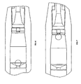
- FIG 1 shows the intravenous i.v. Catheter device in accordance with the present invention wherein the product I.V. Catheter has two washers and a ball positioned below the needle. The needle is fitted in the needle hub and passes through the centric hole in the two washers.
- Figure 5 shows the washer I and II fitted inside the body of the I.V. Catheter.
- Washer Number II which is plain and has a hole in the centre is positioned in the body of catheter at the end closer to the needle hub.
- Washer Number I which has deep grooves and has a hole in the centre is positioned in the body of the catheter at the end closer to plastic tubing fitted to the body of the I.V. Catheter.
- Such a provision of the intravenous (I.V.) Catheter device therefore achieves the required safety in IV cannulation and adapted to protect the user against needle stick injuries.
- the fluid is administered.
- the fluid is administered through the body of the cannula.
- the pressure of fluid would displace the ball stationed at centric hole of washer Number II.
- the pressure of the fluid would take the ball to the centric hole of the washer Number No. I.
- this washer is provided with grooves in the nature of lanes. The fluid would push through the lanes and bypass the ball from distance provided between the ball and hole (by method of grooves).
- the needle withdrawing action is initiated by withdrawing the needle out from the cannula and leaving the plastic tubing inside the body.
- the body of the catheter remains outside.
- the blood will rush from the vein into the body of I.V. Catheter, the blood by its force will push the ball stationed between the washers would be pushed towards washer Number II and block the hole so that the blood became impassable through that hole.
- the dimension of the ball is such that it is more than the circumference of the centric hole of the two washers.
- the above (I.V.) Catheter is adapted to function as safe device to protect the user from exposure to blood during cannulation.
- the above (I.V.) Catheter device can be obtained of simple materials including polypropylene, low density poly ethylene, stainless steel, Fluoropolymer/ Poly urathene.
- the body, needle hub, flash back, are made of polypropylene.
- the needle and ball are made of stainless steel.
- the ball can be made of plastic/ titanium.
Abstract
Description
- The following specification particularly describes the nature of this invention and the manner in which it is to be performed:
This invention relates to a I.V. Catheter and, in particular, to an I.V. Catheter with an inbuilt device to prevent Blood Back Flow. In particular, the intravenous catheter device for the invention has been provided to prevent back flow of blood after cannulation and at the time of withdrawal of needle. - It is well known that when cannulation is done i.e. when needle is inserted in the vein of a patient, blood comes out into the plastic tubing in which the needle is fitted. The purpose of cannulation is to leave the plastic tubing inside the vein and the needle is withdrawn and disposed off. In this process, blood rushes into the tube and body of the I.V. Catheter and even comes out.
- To prevent this, paramedical staff presses the vein to avoid rush of blood. This method is too primitive, uncertain and ineffective in many cases.
-
US patent No. 4,245,635 titled "Catheter assembly for intermittent intravenous use" assigned to Jelco Laboratories discloses a catheter assembly having an elongated hollow tube and a hub connected to the elongated hollow tube. The hub has an interior cavity communicating with a lumen of the elongated hollow tube and also includes an aperture communicating with the cavity. An operable valve includes a closure portion located in the cavity. The operable valve is adapted to close the interior entrance of the aperture under the influence of fluid flowing into the cavity from the lumen after a needle is withdrawn. The operable valve is a ball shaped or cone shaped element to seal the aperture. - A
US patent No. 4,950,254 titled "Valve means for enteral therapy administration set" and assigned to Corpak Inc. discloses a one way valve for incorporation into a fluid administration set for enteral therapy. The valve responds to backflow pressure and arrests retrograde movement of fluid into the set, thereby avoiding rupturing of a tubing in the set. - A
US patent No. 5,263,943 titled "Valved intravenous needle assembly" discloses a needle assembly including an elongate first cylindrical cavity with a first and second end, with the second end formed with a conical recess. The conical recess including a through-extending bore in communication with the recess is directed into a second cavity. The needle assembly prevents reverse fluid flow from the first cylindrical body into the second cylindrical body. - A French patent application No.
2,447,201 - The purpose of this invention is to provide an I.V. Catheter which would by its own mechanism prevent such rush of blood after cannulation.
- Thus according to the basic aspect of the present invention there is provided an intravenous (I.V.) Catheter with inbuilt device to prevent blood back flow comprising:
- The I.V. Catheter comprises of a body, a needle hub capable of holding the needle in a manner that the non sharp end of the needle is fitted inside the needle hub and sharp end is used for cannulation. The needle passes into the plastic tubing for the purpose of cannulation.
- The details of the invention, its objects and advantages are explained hereunder in greater detail in relation to non-limiting exemplary illustration as per the following accompanying figures:
-
-
Figure 1 illustrates an embodiment of the intravenous (I.V.) Catheter. -
Figure 2 is the complete intravenous (I.V.) Catheter wherein the individual parts have been numbered as below:- 1. Portion marked as I is plastic tubing.
- 2. Portion marked as 2 is body of the I.V. Catheter.
- 3. Portion marked as 3 is needle.
- 4. Portion marked as 4 is Catheter holder.
- 5. Portion marked as 5 is needle hub.
- 6. Portion marked as 6 is washer Numbered as I.
- 7. Portion marked as 7 is washer Numbered as II.
- 8. Portion marked as 8 is ball.
-
Figure 3 is an illustration of the washer Numbered as I having deep grooves with hole in the Centre. -
Figure 4 is washer Number II. -
Figure 5 is washer Number I and Number II fitted inside the body of the I.V. Catheter. -
Figures 6 and 7 show the working principle of the invention. - Reference is first invited to accompanying
figure 1 , which shows the intravenous i.v. Catheter device in accordance with the present invention wherein the product I.V. Catheter has two washers and a ball positioned below the needle. The needle is fitted in the needle hub and passes through the centric hole in the two washers. - Reference is now invited to
Figures 3 and4 , which illustrate the washer Number I and washer Number II respectively. - Reference is now invited to accompanying
figure 5 . -
Figure 5 shows the washer I and II fitted inside the body of the I.V. Catheter. Washer Number II which is plain and has a hole in the centre is positioned in the body of catheter at the end closer to the needle hub. Washer Number I which has deep grooves and has a hole in the centre is positioned in the body of the catheter at the end closer to plastic tubing fitted to the body of the I.V. Catheter. - Such a provision of the intravenous (I.V.) Catheter device therefore achieves the required safety in IV cannulation and adapted to protect the user against needle stick injuries.
- The method of application and use of the above safety intravenous (I.V.) Catheter of the invention is further detailed hereunder:-
Thus in use of the catheter device, initially the site of the catheter insertion on the patient's body is cleaned using alcohol wipes. Thereafter, the skin is punctured by using the needle tip which is inside a thin plastic tube. The needle tip is moved forward to puncture the vein. Immediately blood flash back is noticed in the blood collection chamber. - The blood is thus unable to come out from the body and thus spillage is avoided. This is an added safety feature making the user safe from the blood of the patient. Now, the fluid is administered. The fluid is administered through the body of the cannula. The pressure of fluid would displace the ball stationed at centric hole of washer Number II. The pressure of the fluid would take the ball to the centric hole of the washer Number No. I. However, this washer is provided with grooves in the nature of lanes. The fluid would push through the lanes and bypass the ball from distance provided between the ball and hole (by method of grooves).
- Subsequently, the needle withdrawing action is initiated by withdrawing the needle out from the cannula and leaving the plastic tubing inside the body. The body of the catheter remains outside. In this invention, it is proposed that when the blood will rush from the vein into the body of I.V. Catheter, the blood by its force will push the ball stationed between the washers would be pushed towards washer Number II and block the hole so that the blood became impassable through that hole. The dimension of the ball is such that it is more than the circumference of the centric hole of the two washers.
- Advantageously, the above (I.V.) Catheter is adapted to function as safe device to protect the user from exposure to blood during cannulation. The above (I.V.) Catheter device can be obtained of simple materials including polypropylene, low density poly ethylene, stainless steel, Fluoropolymer/ Poly urathene.
- The body, needle hub, flash back, are made of polypropylene. The needle and ball are made of stainless steel. However, the ball can be made of plastic/ titanium.
Claims (8)
- An intravenous (I.V.) Catheter device with a retractable needle comprising:An inbuilt device to prevent blood back flow and where there is a body (2) of the I.V. Catheter, a needle hub (5), a ball (8) characterised by:a washer Number I (6) and a washer Number II (7), wherein the ball (8) is placed between the washer Number I (6) and the washer Number II (7) and wherein the retractable needle passes through a centric hole of the washer Number I (6) and a centric hole of the washer Number II (7) into a plastic tubing (1) and on withdrawal of the needle after cannulation, a flow of blood pushes the ball (8) to the centric hole of the washer Number II (7) and blocks flow and wherein conversely a fluid administered into the body (2) of the I.V catheter pushes the ball (8) to the centric hole of the washer Number I (6) and fluid get passage through grooves present in the washer Number I(6).
- The intravenous (I.V.) Catheter device as claimed in claim 1, wherein the ball (8) is positioned below the needle.
- The intravenous (I.V.) catheter as claimed in claim 1, wherein the washer Number I (6) is positioned at an end closer to the needle hub (5).
- The intravenous (I.V.) catheter device as claimed in claim 1, wherein the washer Number II (7) is positioned in the body (2) of the I.V catheter at an end, closer to the plastic tubing (1) fitted to the body (2) of the I.V. Catheter.
- The intravenous (I.V.) Catheter device as claimed in claim 1, wherein the ball (8) is larger then the outer circumference of the centric hole of the washer Number I (6) and the centric hole of the washer Number II (7).
- The intravenous (I.V.) Catheter device as claimed in claim 1, wherein the ball (8) comprises one of stainless steel, titanium or plastic.
- The intravenous (I.V.) Catheter device as claimed in claim 1, wherein the needle comprises stainless steel.
- The intravenous (I.V.) Catheter device as claimed in claim 1, wherein the body (2) and/or the needle hub (5) of the I.V. Catheter comprise polypropylene.
Applications Claiming Priority (1)
| Application Number | Priority Date | Filing Date | Title |
|---|---|---|---|
| IN23KO2008 | 2008-01-03 |
Publications (2)
| Publication Number | Publication Date |
|---|---|
| EP2077134A1 EP2077134A1 (en) | 2009-07-08 |
| EP2077134B1 true EP2077134B1 (en) | 2010-12-01 |
Family
ID=40419159
Family Applications (1)
| Application Number | Title | Priority Date | Filing Date |
|---|---|---|---|
| EP08164267A Not-in-force EP2077134B1 (en) | 2008-01-03 | 2008-09-12 | Safety I.V. catheter with in-built device to prevent blood back flow |
Country Status (4)
| Country | Link |
|---|---|
| EP (1) | EP2077134B1 (en) |
| AT (1) | ATE489988T1 (en) |
| DE (1) | DE602008003742D1 (en) |
| ES (1) | ES2362023T3 (en) |
Families Citing this family (2)
| Publication number | Priority date | Publication date | Assignee | Title |
|---|---|---|---|---|
| CN102091378B (en) * | 2011-02-16 | 2013-05-22 | 北京福尔安娜科技发展有限公司 | Retaining needle capable of being closed by virtue of positive pressure and displaying blood back |
| KR102078871B1 (en) * | 2018-05-04 | 2020-02-19 | 정연문 | Electrode devices for spinal surgery |
Family Cites Families (6)
| Publication number | Priority date | Publication date | Assignee | Title |
|---|---|---|---|---|
| US4261357A (en) | 1979-01-29 | 1981-04-14 | Critikon, Inc. | Catheter assembly for intermittent intravenous medicament delivery |
| US4245635A (en) | 1979-01-29 | 1981-01-20 | Jelco Laboratories | Catheter assembly for intermittent intravenous use |
| US4950254A (en) | 1988-10-14 | 1990-08-21 | Corpak, Inc. | Valve means for enteral therapy administration set |
| US5263943A (en) | 1992-08-24 | 1993-11-23 | Vanderbrook Bernard E | Valved intravenous needle assembly |
| US5743883A (en) * | 1995-06-07 | 1998-04-28 | Visconti; Peter L. | Thoracentesis catheter instruments having self-sealing valves |
| US20050283123A1 (en) * | 2004-06-18 | 2005-12-22 | Lyde Felicia C | AVAP: air valve and port for intravenous (IV) tubing |
-
2008
- 2008-09-12 DE DE602008003742T patent/DE602008003742D1/en active Active
- 2008-09-12 AT AT08164267T patent/ATE489988T1/en not_active IP Right Cessation
- 2008-09-12 ES ES08164267T patent/ES2362023T3/en active Active
- 2008-09-12 EP EP08164267A patent/EP2077134B1/en not_active Not-in-force
Also Published As
| Publication number | Publication date |
|---|---|
| ES2362023T3 (en) | 2011-06-27 |
| EP2077134A1 (en) | 2009-07-08 |
| ATE489988T1 (en) | 2010-12-15 |
| DE602008003742D1 (en) | 2011-01-13 |
Similar Documents
| Publication | Publication Date | Title |
|---|---|---|
| US7534233B2 (en) | Flush syringe having anti-reflux features | |
| JP6396898B2 (en) | Clip syringe | |
| US20030199816A1 (en) | Pre-loaded multi-chamber syringe | |
| US20050063857A1 (en) | Flush syringe having anti-reflux stopper | |
| RU2428214C2 (en) | Ampoule applied as syringe, and syringe comprising ampoule | |
| US20080119794A1 (en) | Flush syringe having anti-reflux stopper | |
| WO2012174109A1 (en) | Intravenous catheter introducer with needle retraction controlled by catheter hub seal | |
| JP2006501944A (en) | Flash syringe with compressible plunger | |
| GB2214819A (en) | A device for use in surgical procedures | |
| CN105013045A (en) | Positive-pressure continuous liquid supply device, venous indwelling needle and central venous catheter | |
| EP2077134B1 (en) | Safety I.V. catheter with in-built device to prevent blood back flow | |
| US20060030820A1 (en) | Flush syringe having anti-reflux features | |
| CN103110998B (en) | There is the intravenous pin of the visual blood back function of rapid sensitive | |
| CN201537286U (en) | Flushing injector | |
| WO2015027427A1 (en) | Device for puncturing heparin cap and vascular access system | |
| EP2168628A1 (en) | Safety I.V. catheter with a rotator and inbuilt plug to prevent blood back flow | |
| JP2001299929A (en) | Safety catheter provided with meandering fluid passage | |
| CN104826194A (en) | Intravenous infusion injection needle | |
| CN211157835U (en) | Pre-filling type washing tube sealing syringe | |
| CN213883425U (en) | Disposable anti-liquid-flow puncture needle | |
| CN111840066A (en) | Blood bag puncture-preventing device | |
| JP3648220B2 (en) | Side pipe |
Legal Events
| Date | Code | Title | Description |
|---|---|---|---|
| PUAI | Public reference made under article 153(3) epc to a published international application that has entered the european phase |
Free format text: ORIGINAL CODE: 0009012 |
|
| 17P | Request for examination filed |
Effective date: 20090514 |
|
| AK | Designated contracting states |
Kind code of ref document: A1 Designated state(s): AT BE BG CH CY CZ DE DK EE ES FI FR GB GR HR HU IE IS IT LI LT LU LV MC MT NL NO PL PT RO SE SI SK TR |
|
| AX | Request for extension of the european patent |
Extension state: AL BA MK RS |
|
| 17Q | First examination report despatched |
Effective date: 20090821 |
|
| AKX | Designation fees paid |
Designated state(s): AT BE BG CH CY CZ DE DK EE ES FI FR GB GR HR HU IE IS IT LI LT LU LV MC MT NL NO PL PT RO SE SI SK TR |
|
| GRAP | Despatch of communication of intention to grant a patent |
Free format text: ORIGINAL CODE: EPIDOSNIGR1 |
|
| GRAS | Grant fee paid |
Free format text: ORIGINAL CODE: EPIDOSNIGR3 |
|
| GRAA | (expected) grant |
Free format text: ORIGINAL CODE: 0009210 |
|
| AK | Designated contracting states |
Kind code of ref document: B1 Designated state(s): AT BE BG CH CY CZ DE DK EE ES FI FR GB GR HR HU IE IS IT LI LT LU LV MC MT NL NO PL PT RO SE SI SK TR |
|
| REG | Reference to a national code |
Ref country code: GB Ref legal event code: FG4D |
|
| REG | Reference to a national code |
Ref country code: CH Ref legal event code: EP |
|
| REG | Reference to a national code |
Ref country code: IE Ref legal event code: FG4D |
|
| REF | Corresponds to: |
Ref document number: 602008003742 Country of ref document: DE Date of ref document: 20110113 Kind code of ref document: P |
|
| REG | Reference to a national code |
Ref country code: NL Ref legal event code: VDEP Effective date: 20101201 |
|
| PG25 | Lapsed in a contracting state [announced via postgrant information from national office to epo] |
Ref country code: LT Free format text: LAPSE BECAUSE OF FAILURE TO SUBMIT A TRANSLATION OF THE DESCRIPTION OR TO PAY THE FEE WITHIN THE PRESCRIBED TIME-LIMIT Effective date: 20101201 Ref country code: NO Free format text: LAPSE BECAUSE OF FAILURE TO SUBMIT A TRANSLATION OF THE DESCRIPTION OR TO PAY THE FEE WITHIN THE PRESCRIBED TIME-LIMIT Effective date: 20110301 |
|
| LTIE | Lt: invalidation of european patent or patent extension |
Effective date: 20101201 |
|
| PG25 | Lapsed in a contracting state [announced via postgrant information from national office to epo] |
Ref country code: BG Free format text: LAPSE BECAUSE OF FAILURE TO SUBMIT A TRANSLATION OF THE DESCRIPTION OR TO PAY THE FEE WITHIN THE PRESCRIBED TIME-LIMIT Effective date: 20110301 Ref country code: AT Free format text: LAPSE BECAUSE OF FAILURE TO SUBMIT A TRANSLATION OF THE DESCRIPTION OR TO PAY THE FEE WITHIN THE PRESCRIBED TIME-LIMIT Effective date: 20101201 Ref country code: HR Free format text: LAPSE BECAUSE OF FAILURE TO SUBMIT A TRANSLATION OF THE DESCRIPTION OR TO PAY THE FEE WITHIN THE PRESCRIBED TIME-LIMIT Effective date: 20101201 Ref country code: FI Free format text: LAPSE BECAUSE OF FAILURE TO SUBMIT A TRANSLATION OF THE DESCRIPTION OR TO PAY THE FEE WITHIN THE PRESCRIBED TIME-LIMIT Effective date: 20101201 Ref country code: LV Free format text: LAPSE BECAUSE OF FAILURE TO SUBMIT A TRANSLATION OF THE DESCRIPTION OR TO PAY THE FEE WITHIN THE PRESCRIBED TIME-LIMIT Effective date: 20101201 Ref country code: NL Free format text: LAPSE BECAUSE OF FAILURE TO SUBMIT A TRANSLATION OF THE DESCRIPTION OR TO PAY THE FEE WITHIN THE PRESCRIBED TIME-LIMIT Effective date: 20101201 Ref country code: CY Free format text: LAPSE BECAUSE OF FAILURE TO SUBMIT A TRANSLATION OF THE DESCRIPTION OR TO PAY THE FEE WITHIN THE PRESCRIBED TIME-LIMIT Effective date: 20101201 Ref country code: SI Free format text: LAPSE BECAUSE OF FAILURE TO SUBMIT A TRANSLATION OF THE DESCRIPTION OR TO PAY THE FEE WITHIN THE PRESCRIBED TIME-LIMIT Effective date: 20101201 Ref country code: SE Free format text: LAPSE BECAUSE OF FAILURE TO SUBMIT A TRANSLATION OF THE DESCRIPTION OR TO PAY THE FEE WITHIN THE PRESCRIBED TIME-LIMIT Effective date: 20101201 |
|
| REG | Reference to a national code |
Ref country code: ES Ref legal event code: FG2A Ref document number: 2362023 Country of ref document: ES Kind code of ref document: T3 Effective date: 20110627 |
|
| PG25 | Lapsed in a contracting state [announced via postgrant information from national office to epo] |
Ref country code: GR Free format text: LAPSE BECAUSE OF FAILURE TO SUBMIT A TRANSLATION OF THE DESCRIPTION OR TO PAY THE FEE WITHIN THE PRESCRIBED TIME-LIMIT Effective date: 20110302 |
|
| PG25 | Lapsed in a contracting state [announced via postgrant information from national office to epo] |
Ref country code: CZ Free format text: LAPSE BECAUSE OF FAILURE TO SUBMIT A TRANSLATION OF THE DESCRIPTION OR TO PAY THE FEE WITHIN THE PRESCRIBED TIME-LIMIT Effective date: 20101201 Ref country code: EE Free format text: LAPSE BECAUSE OF FAILURE TO SUBMIT A TRANSLATION OF THE DESCRIPTION OR TO PAY THE FEE WITHIN THE PRESCRIBED TIME-LIMIT Effective date: 20101201 Ref country code: BE Free format text: LAPSE BECAUSE OF FAILURE TO SUBMIT A TRANSLATION OF THE DESCRIPTION OR TO PAY THE FEE WITHIN THE PRESCRIBED TIME-LIMIT Effective date: 20101201 Ref country code: PT Free format text: LAPSE BECAUSE OF FAILURE TO SUBMIT A TRANSLATION OF THE DESCRIPTION OR TO PAY THE FEE WITHIN THE PRESCRIBED TIME-LIMIT Effective date: 20110401 Ref country code: IS Free format text: LAPSE BECAUSE OF FAILURE TO SUBMIT A TRANSLATION OF THE DESCRIPTION OR TO PAY THE FEE WITHIN THE PRESCRIBED TIME-LIMIT Effective date: 20110401 |
|
| PG25 | Lapsed in a contracting state [announced via postgrant information from national office to epo] |
Ref country code: SK Free format text: LAPSE BECAUSE OF FAILURE TO SUBMIT A TRANSLATION OF THE DESCRIPTION OR TO PAY THE FEE WITHIN THE PRESCRIBED TIME-LIMIT Effective date: 20101201 Ref country code: PL Free format text: LAPSE BECAUSE OF FAILURE TO SUBMIT A TRANSLATION OF THE DESCRIPTION OR TO PAY THE FEE WITHIN THE PRESCRIBED TIME-LIMIT Effective date: 20101201 Ref country code: RO Free format text: LAPSE BECAUSE OF FAILURE TO SUBMIT A TRANSLATION OF THE DESCRIPTION OR TO PAY THE FEE WITHIN THE PRESCRIBED TIME-LIMIT Effective date: 20101201 |
|
| PLBE | No opposition filed within time limit |
Free format text: ORIGINAL CODE: 0009261 |
|
| STAA | Information on the status of an ep patent application or granted ep patent |
Free format text: STATUS: NO OPPOSITION FILED WITHIN TIME LIMIT |
|
| PG25 | Lapsed in a contracting state [announced via postgrant information from national office to epo] |
Ref country code: DK Free format text: LAPSE BECAUSE OF FAILURE TO SUBMIT A TRANSLATION OF THE DESCRIPTION OR TO PAY THE FEE WITHIN THE PRESCRIBED TIME-LIMIT Effective date: 20101201 |
|
| 26N | No opposition filed |
Effective date: 20110902 |
|
| REG | Reference to a national code |
Ref country code: DE Ref legal event code: R097 Ref document number: 602008003742 Country of ref document: DE Effective date: 20110902 |
|
| PGFP | Annual fee paid to national office [announced via postgrant information from national office to epo] |
Ref country code: IT Payment date: 20110930 Year of fee payment: 4 |
|
| PG25 | Lapsed in a contracting state [announced via postgrant information from national office to epo] |
Ref country code: MC Free format text: LAPSE BECAUSE OF NON-PAYMENT OF DUE FEES Effective date: 20110930 |
|
| REG | Reference to a national code |
Ref country code: IE Ref legal event code: MM4A |
|
| REG | Reference to a national code |
Ref country code: FR Ref legal event code: ST Effective date: 20120531 |
|
| PG25 | Lapsed in a contracting state [announced via postgrant information from national office to epo] |
Ref country code: IE Free format text: LAPSE BECAUSE OF NON-PAYMENT OF DUE FEES Effective date: 20110912 Ref country code: DE Free format text: LAPSE BECAUSE OF NON-PAYMENT OF DUE FEES Effective date: 20120403 |
|
| REG | Reference to a national code |
Ref country code: DE Ref legal event code: R119 Ref document number: 602008003742 Country of ref document: DE Effective date: 20120403 |
|
| PG25 | Lapsed in a contracting state [announced via postgrant information from national office to epo] |
Ref country code: FR Free format text: LAPSE BECAUSE OF NON-PAYMENT OF DUE FEES Effective date: 20110930 |
|
| PG25 | Lapsed in a contracting state [announced via postgrant information from national office to epo] |
Ref country code: MT Free format text: LAPSE BECAUSE OF FAILURE TO SUBMIT A TRANSLATION OF THE DESCRIPTION OR TO PAY THE FEE WITHIN THE PRESCRIBED TIME-LIMIT Effective date: 20101201 |
|
| REG | Reference to a national code |
Ref country code: ES Ref legal event code: FD2A Effective date: 20130417 |
|
| PG25 | Lapsed in a contracting state [announced via postgrant information from national office to epo] |
Ref country code: ES Free format text: LAPSE BECAUSE OF NON-PAYMENT OF DUE FEES Effective date: 20110913 |
|
| REG | Reference to a national code |
Ref country code: CH Ref legal event code: PL |
|
| GBPC | Gb: european patent ceased through non-payment of renewal fee |
Effective date: 20120912 |
|
| PG25 | Lapsed in a contracting state [announced via postgrant information from national office to epo] |
Ref country code: LU Free format text: LAPSE BECAUSE OF NON-PAYMENT OF DUE FEES Effective date: 20110912 |
|
| PG25 | Lapsed in a contracting state [announced via postgrant information from national office to epo] |
Ref country code: LI Free format text: LAPSE BECAUSE OF NON-PAYMENT OF DUE FEES Effective date: 20120930 Ref country code: CH Free format text: LAPSE BECAUSE OF NON-PAYMENT OF DUE FEES Effective date: 20120930 Ref country code: GB Free format text: LAPSE BECAUSE OF NON-PAYMENT OF DUE FEES Effective date: 20120912 |
|
| PG25 | Lapsed in a contracting state [announced via postgrant information from national office to epo] |
Ref country code: IT Free format text: LAPSE BECAUSE OF NON-PAYMENT OF DUE FEES Effective date: 20120912 |
|
| PG25 | Lapsed in a contracting state [announced via postgrant information from national office to epo] |
Ref country code: TR Free format text: LAPSE BECAUSE OF FAILURE TO SUBMIT A TRANSLATION OF THE DESCRIPTION OR TO PAY THE FEE WITHIN THE PRESCRIBED TIME-LIMIT Effective date: 20101201 |
|
| PG25 | Lapsed in a contracting state [announced via postgrant information from national office to epo] |
Ref country code: HU Free format text: LAPSE BECAUSE OF FAILURE TO SUBMIT A TRANSLATION OF THE DESCRIPTION OR TO PAY THE FEE WITHIN THE PRESCRIBED TIME-LIMIT Effective date: 20101201 |