EP2076934B1 - L'utilisation d'un electrolyte ceramique conducteur de protons - Google Patents
L'utilisation d'un electrolyte ceramique conducteur de protons Download PDFInfo
- Publication number
- EP2076934B1 EP2076934B1 EP07858516.3A EP07858516A EP2076934B1 EP 2076934 B1 EP2076934 B1 EP 2076934B1 EP 07858516 A EP07858516 A EP 07858516A EP 2076934 B1 EP2076934 B1 EP 2076934B1
- Authority
- EP
- European Patent Office
- Prior art keywords
- proton
- ceramic
- hydrogen
- temperature
- conductivity
- Prior art date
- Legal status (The legal status is an assumption and is not a legal conclusion. Google has not performed a legal analysis and makes no representation as to the accuracy of the status listed.)
- Not-in-force
Links
Images




Classifications
-
- H—ELECTRICITY
- H01—ELECTRIC ELEMENTS
- H01M—PROCESSES OR MEANS, e.g. BATTERIES, FOR THE DIRECT CONVERSION OF CHEMICAL ENERGY INTO ELECTRICAL ENERGY
- H01M8/00—Fuel cells; Manufacture thereof
- H01M8/10—Fuel cells with solid electrolytes
- H01M8/12—Fuel cells with solid electrolytes operating at high temperature, e.g. with stabilised ZrO2 electrolyte
- H01M8/124—Fuel cells with solid electrolytes operating at high temperature, e.g. with stabilised ZrO2 electrolyte characterised by the process of manufacturing or by the material of the electrolyte
- H01M8/1246—Fuel cells with solid electrolytes operating at high temperature, e.g. with stabilised ZrO2 electrolyte characterised by the process of manufacturing or by the material of the electrolyte the electrolyte consisting of oxides
-
- B—PERFORMING OPERATIONS; TRANSPORTING
- B01—PHYSICAL OR CHEMICAL PROCESSES OR APPARATUS IN GENERAL
- B01D—SEPARATION
- B01D71/00—Semi-permeable membranes for separation processes or apparatus characterised by the material; Manufacturing processes specially adapted therefor
- B01D71/02—Inorganic material
- B01D71/024—Oxides
- B01D71/0271—Perovskites
-
- C—CHEMISTRY; METALLURGY
- C25—ELECTROLYTIC OR ELECTROPHORETIC PROCESSES; APPARATUS THEREFOR
- C25B—ELECTROLYTIC OR ELECTROPHORETIC PROCESSES FOR THE PRODUCTION OF COMPOUNDS OR NON-METALS; APPARATUS THEREFOR
- C25B1/00—Electrolytic production of inorganic compounds or non-metals
- C25B1/01—Products
- C25B1/02—Hydrogen or oxygen
- C25B1/04—Hydrogen or oxygen by electrolysis of water
-
- C—CHEMISTRY; METALLURGY
- C25—ELECTROLYTIC OR ELECTROPHORETIC PROCESSES; APPARATUS THEREFOR
- C25B—ELECTROLYTIC OR ELECTROPHORETIC PROCESSES FOR THE PRODUCTION OF COMPOUNDS OR NON-METALS; APPARATUS THEREFOR
- C25B13/00—Diaphragms; Spacing elements
- C25B13/04—Diaphragms; Spacing elements characterised by the material
-
- C—CHEMISTRY; METALLURGY
- C25—ELECTROLYTIC OR ELECTROPHORETIC PROCESSES; APPARATUS THEREFOR
- C25B—ELECTROLYTIC OR ELECTROPHORETIC PROCESSES FOR THE PRODUCTION OF COMPOUNDS OR NON-METALS; APPARATUS THEREFOR
- C25B13/00—Diaphragms; Spacing elements
- C25B13/04—Diaphragms; Spacing elements characterised by the material
- C25B13/05—Diaphragms; Spacing elements characterised by the material based on inorganic materials
- C25B13/07—Diaphragms; Spacing elements characterised by the material based on inorganic materials based on ceramics
-
- C—CHEMISTRY; METALLURGY
- C25—ELECTROLYTIC OR ELECTROPHORETIC PROCESSES; APPARATUS THEREFOR
- C25B—ELECTROLYTIC OR ELECTROPHORETIC PROCESSES FOR THE PRODUCTION OF COMPOUNDS OR NON-METALS; APPARATUS THEREFOR
- C25B9/00—Cells or assemblies of cells; Constructional parts of cells; Assemblies of constructional parts, e.g. electrode-diaphragm assemblies; Process-related cell features
- C25B9/17—Cells comprising dimensionally-stable non-movable electrodes; Assemblies of constructional parts thereof
- C25B9/19—Cells comprising dimensionally-stable non-movable electrodes; Assemblies of constructional parts thereof with diaphragms
-
- H—ELECTRICITY
- H01—ELECTRIC ELEMENTS
- H01M—PROCESSES OR MEANS, e.g. BATTERIES, FOR THE DIRECT CONVERSION OF CHEMICAL ENERGY INTO ELECTRICAL ENERGY
- H01M8/00—Fuel cells; Manufacture thereof
- H01M8/10—Fuel cells with solid electrolytes
- H01M8/1016—Fuel cells with solid electrolytes characterised by the electrolyte material
-
- H—ELECTRICITY
- H01—ELECTRIC ELEMENTS
- H01M—PROCESSES OR MEANS, e.g. BATTERIES, FOR THE DIRECT CONVERSION OF CHEMICAL ENERGY INTO ELECTRICAL ENERGY
- H01M8/00—Fuel cells; Manufacture thereof
- H01M8/10—Fuel cells with solid electrolytes
- H01M8/12—Fuel cells with solid electrolytes operating at high temperature, e.g. with stabilised ZrO2 electrolyte
-
- H—ELECTRICITY
- H01—ELECTRIC ELEMENTS
- H01M—PROCESSES OR MEANS, e.g. BATTERIES, FOR THE DIRECT CONVERSION OF CHEMICAL ENERGY INTO ELECTRICAL ENERGY
- H01M8/00—Fuel cells; Manufacture thereof
- H01M8/10—Fuel cells with solid electrolytes
- H01M8/12—Fuel cells with solid electrolytes operating at high temperature, e.g. with stabilised ZrO2 electrolyte
- H01M8/124—Fuel cells with solid electrolytes operating at high temperature, e.g. with stabilised ZrO2 electrolyte characterised by the process of manufacturing or by the material of the electrolyte
- H01M8/1246—Fuel cells with solid electrolytes operating at high temperature, e.g. with stabilised ZrO2 electrolyte characterised by the process of manufacturing or by the material of the electrolyte the electrolyte consisting of oxides
- H01M8/1253—Fuel cells with solid electrolytes operating at high temperature, e.g. with stabilised ZrO2 electrolyte characterised by the process of manufacturing or by the material of the electrolyte the electrolyte consisting of oxides the electrolyte containing zirconium oxide
-
- B—PERFORMING OPERATIONS; TRANSPORTING
- B01—PHYSICAL OR CHEMICAL PROCESSES OR APPARATUS IN GENERAL
- B01D—SEPARATION
- B01D2325/00—Details relating to properties of membranes
- B01D2325/26—Electrical properties
-
- H—ELECTRICITY
- H01—ELECTRIC ELEMENTS
- H01M—PROCESSES OR MEANS, e.g. BATTERIES, FOR THE DIRECT CONVERSION OF CHEMICAL ENERGY INTO ELECTRICAL ENERGY
- H01M8/00—Fuel cells; Manufacture thereof
- H01M8/10—Fuel cells with solid electrolytes
- H01M8/12—Fuel cells with solid electrolytes operating at high temperature, e.g. with stabilised ZrO2 electrolyte
- H01M2008/1293—Fuel cells with solid oxide electrolytes
-
- H—ELECTRICITY
- H01—ELECTRIC ELEMENTS
- H01M—PROCESSES OR MEANS, e.g. BATTERIES, FOR THE DIRECT CONVERSION OF CHEMICAL ENERGY INTO ELECTRICAL ENERGY
- H01M2300/00—Electrolytes
- H01M2300/0017—Non-aqueous electrolytes
- H01M2300/0065—Solid electrolytes
- H01M2300/0068—Solid electrolytes inorganic
- H01M2300/0071—Oxides
- H01M2300/0074—Ion conductive at high temperature
-
- H—ELECTRICITY
- H01—ELECTRIC ELEMENTS
- H01M—PROCESSES OR MEANS, e.g. BATTERIES, FOR THE DIRECT CONVERSION OF CHEMICAL ENERGY INTO ELECTRICAL ENERGY
- H01M2300/00—Electrolytes
- H01M2300/0017—Non-aqueous electrolytes
- H01M2300/0065—Solid electrolytes
- H01M2300/0068—Solid electrolytes inorganic
- H01M2300/0071—Oxides
- H01M2300/0074—Ion conductive at high temperature
- H01M2300/0077—Ion conductive at high temperature based on zirconium oxide
-
- Y—GENERAL TAGGING OF NEW TECHNOLOGICAL DEVELOPMENTS; GENERAL TAGGING OF CROSS-SECTIONAL TECHNOLOGIES SPANNING OVER SEVERAL SECTIONS OF THE IPC; TECHNICAL SUBJECTS COVERED BY FORMER USPC CROSS-REFERENCE ART COLLECTIONS [XRACs] AND DIGESTS
- Y02—TECHNOLOGIES OR APPLICATIONS FOR MITIGATION OR ADAPTATION AGAINST CLIMATE CHANGE
- Y02E—REDUCTION OF GREENHOUSE GAS [GHG] EMISSIONS, RELATED TO ENERGY GENERATION, TRANSMISSION OR DISTRIBUTION
- Y02E60/00—Enabling technologies; Technologies with a potential or indirect contribution to GHG emissions mitigation
- Y02E60/30—Hydrogen technology
- Y02E60/36—Hydrogen production from non-carbon containing sources, e.g. by water electrolysis
-
- Y—GENERAL TAGGING OF NEW TECHNOLOGICAL DEVELOPMENTS; GENERAL TAGGING OF CROSS-SECTIONAL TECHNOLOGIES SPANNING OVER SEVERAL SECTIONS OF THE IPC; TECHNICAL SUBJECTS COVERED BY FORMER USPC CROSS-REFERENCE ART COLLECTIONS [XRACs] AND DIGESTS
- Y02—TECHNOLOGIES OR APPLICATIONS FOR MITIGATION OR ADAPTATION AGAINST CLIMATE CHANGE
- Y02E—REDUCTION OF GREENHOUSE GAS [GHG] EMISSIONS, RELATED TO ENERGY GENERATION, TRANSMISSION OR DISTRIBUTION
- Y02E60/00—Enabling technologies; Technologies with a potential or indirect contribution to GHG emissions mitigation
- Y02E60/30—Hydrogen technology
- Y02E60/50—Fuel cells
-
- Y—GENERAL TAGGING OF NEW TECHNOLOGICAL DEVELOPMENTS; GENERAL TAGGING OF CROSS-SECTIONAL TECHNOLOGIES SPANNING OVER SEVERAL SECTIONS OF THE IPC; TECHNICAL SUBJECTS COVERED BY FORMER USPC CROSS-REFERENCE ART COLLECTIONS [XRACs] AND DIGESTS
- Y02—TECHNOLOGIES OR APPLICATIONS FOR MITIGATION OR ADAPTATION AGAINST CLIMATE CHANGE
- Y02P—CLIMATE CHANGE MITIGATION TECHNOLOGIES IN THE PRODUCTION OR PROCESSING OF GOODS
- Y02P70/00—Climate change mitigation technologies in the production process for final industrial or consumer products
- Y02P70/50—Manufacturing or production processes characterised by the final manufactured product
Definitions
- the present invention relates to an electrochemical device, such as a fuel cell or an electrolysis cell, containing, as electrolyte, a barium and indium-based proton conducting ceramic as well as the use of such a ceramic as a proton conductor in an electrochemical device at a temperature of between 200 ° C and 600 ° C.
- Fuel cells are electrochemical generators that continuously convert, without direct combustion, gases such as H 2 and O 2 into electricity and heat through the electrochemical reactions occurring at the electrolyte-separated electrodes. For reasons essentially related to the reliability of operation and industrialization constraints in mass production, the choice of fuel cells comprising a solid electrolyte is particularly interesting.
- PEMFC Proton Exchange Membrane Fuel Cell
- SOFC Solid Oxide Fuel Cell
- PEMFCs The main disadvantage of PEMFCs is the need for hydration of the proton-conducting membrane and the poor thermal stability of the polymer materials, which limits the use of such cells to a temperature range below 120 ° C and therefore involves the use in the electrodes of expensive platinum catalysts sensitive to poisoning by carbon monoxide.
- SOFC technology which involves operation at temperatures generally above 700 ° C, has many advantages over PEMFCs, such as high electrical efficiency, often greater than 45%, the possibility of using carbon monoxide as fuel, to do direct reforming and the absence of expensive catalysts.
- the high operating temperature of these cells induces a long-term loss of stability, a long start-up time and a low capacity to withstand thermal cycles.
- the challenge for SOFCs is to reduce the operating temperature in order to limit the degradation reactions at the interfaces, to improve resistance to thermal cycling and thus to increase the battery life.
- the proton conducting ceramics in question are known per se and have been described in particular in the article of V. Jayaraman et al., Published in Solid State Ionics, 170, (2004), pages 25-32 . These materials are based on oxygen-deficient barium and indium oxide, the gaps of which are at least partially filled by hydroxyl groups reversibly fixed by hydration of the materials. Jayaraman et al., In the cited article, evaluated the proton conductivity of ceramic materials at temperatures ranging from room temperature to about 180 ° C and obtained unsatisfactory results, the maximum proton conductivity at 180 ° C not exceeding not 10 -6 S.cm -1 .
- the present invention is based on the discovery that, despite the phenomenon of dehydration of the ceramic material, observed above 200 ° C, the materials described in this article have a high proton conductivity at temperatures between 200 ° C and 600 ° C, and can therefore be used as a solid electrolyte in fuel cells, but also in other electrochemical devices using protonic conductors, such as electrolysis cells, hydrogen separation membranes or hydrogen detectors.
- the present invention therefore relates to the use of a ceramic of formula (I) Ba 2 In 2 (1-y) Ti 2y O 4 + ⁇ (OH) ⁇ , or 0 ⁇ y ⁇ 0.3, ⁇ ⁇ 2 and 0 ⁇ ' ⁇ 2, as a proton-conducting solid electrolyte in an electrochemical device selected from a fuel cell, an electrolysis cell, a separation membrane hydrogen from a gaseous mixture, or a hydrogen detector.
- a ceramic of formula (I) Ba 2 In 2 (1-y) Ti 2y O 4 + ⁇ (OH) ⁇ , or 0 ⁇ y ⁇ 0.3, ⁇ ⁇ 2 and 0 ⁇ ' ⁇ 2 as a proton-conducting solid electrolyte in an electrochemical device selected from a fuel cell, an electrolysis cell, a separation membrane hydrogen from a gaseous mixture, or a hydrogen detector.
- the ceramic material is used in the temperature range where its proton conductivity is maximum, that is to say at a temperature of between 200 ° C and 600 ° C, in particular between 300 ° C and 500 ° C.
- the present invention further discloses such an electrochemical device containing a proton-conducting solid electrolyte made of a ceramic of formula (I) (I) Ba 2 In 2 (1-y) Ti 2 y O 4 , ⁇ (OH) ⁇ ' or 0 ⁇ y ⁇ 0, 3, ⁇ ⁇ 2 and 0 ⁇ ' ⁇ 2.
- the electrochemical device is a fuel cell comprising an anode compartment, with an anode, fed continuously with hydrogen or with a mixture of gases containing hydrogen and a cathode compartment. with a cathode, fed with oxygen or air, the two compartments being separated by the proton conductive electrolyte of formula (I) above.
- the electrochemical device is an electrolysis cell, comprising a negative electrode, or cathode, and a positive electrode, or anode, separated from each other by a proton conducting electrolyte of formula ( I) above.
- the device is a hydrogen purification membrane comprising a positive electrode and a negative electrode separated by a proton conducting ceramic of formula (I) above.
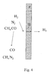
- the device is a hydrogen purification membrane formed by a sintered solid containing a percolating mixture (i) of particles of at least one electronically conductive material, and (ii) particles of at least a proton conducting ceramic of formula (I) above.
- Such an electrochemical device when it is a fuel cell, combines many advantages of SOFC or SMEFC type fuel cells described in the introduction, without suffering the disadvantages thereof.
- Such a device can operate in mobile or stationary applications. It presents, like SOFCs, a high electrical efficiency and a high temperature of cogeneration and is distinguished from SOFC mainly by a much lower optimum operating temperature of between 200 ° C and 600 ° C. This reduction in operating temperature results in an increase in the life of the electrochemical devices, a better resistance to thermal cycling, and allows the replacement of expensive ceramics and steels, used for the SOFC interconnectors, with standard steels.
- the electrochemical devices of the present invention do not require expensive platinum catalysts and are insensitive to carbon monoxide poisoning.
- the proton conducting ceramic material used as the solid electrolyte in the electrochemical device of the present invention must have negligible electronic conductivity in order to avoid short circuits. It must also be impermeable to gases and is preferably in the form of a sintered material with closed porosity. This closed porosity is preferably reduced to a minimum, that is to say the ceramic material advantageously has a high degree of compactness, preferably greater than 95%.
- the ceramic materials of formula (I) above are distinguished by excellent sinterability: they can be compacted to the desired degree of compactness, greater than 95%, by sintering at a relatively low temperature, less than or equal to 1400 ° C, and typically between 1300 ° C and 1400 ° C.
- Another advantage of the ceramic materials of formula (I) lies in the fact that, unlike other ceramic materials, they do not react, in the temperature range of from 200 ° C. to about 550 ° C., with the carbon dioxide. carbon that may be present in the anode compartment of the cell.
- the formation of carbonates is one of the factors that limit the operating temperature of the electrochemical device of the present invention in the presence of CO 2 .
- the proton conducting ceramic material of the present invention has a perovskite crystal structure derived from Ba 2 In 2 O 5 by partial replacement of barium and / or indium ions and hydration of least part of the oxygen vacancies with formation of hydroxyl groups, essential for the protonic conduction of ceramic materials.
- the protonic conduction of ceramic materials results from the transfer of protons between (OH) - and O 2- groups , known as the Grotthus mechanism.
- the level of conductivity at a certain temperature is related to the mobility of the proton and its concentration.
- the proton concentration directly depends on the density of the hydroxyl groups introduced into the material by the hydration reaction of the oxygen vacancies.
- the concentration of the oxygen vacancies can, in turn, be modulated by replacing a portion of the barium and / or indium ions with Ti metal ions having a different oxidation state.
- the proton mobility is a function of the ease with which they break their OH bond with the oxygen of the hydroxyl group bonded to a metal cation. This mobility therefore depends on the more or less ionic or covalent nature of the oxygen-metal cation bond. Thus, the level of proton conductivity strongly depends on the composition and concentration of metal elements.
- the Applicant has obtained excellent results, especially in terms of conductivity, with ceramic materials in which the barium ions were not replaced by other metal cations and only a small fraction of the indium ions, less than 30%, was replaced by Ti (IV) ions.
- the solid electrolyte proton conductor according to the invention is therefore a ceramic of formula (Ia) (Ia) Ba 2 In 2 (1-y) Ti 2 y O 4 + ⁇ (OH) ⁇ ' where 0 ⁇ y ⁇ 0.3, ⁇ ⁇ 2 and 0 ⁇ ' ⁇ 2.
- the performance of the ceramic materials used in the present invention does not depend solely on the metal cation composition and the number of oxygen vacancies, but on the rate of hydration of the gaps, each fixed molecule of water leading to the disappearance a gap and the formation of two hydroxyl groups.
- the hydration reaction is a reversible reaction whose equilibrium constant directly depends on the operating temperature of the electrochemical device.
- Jayaraman et al. Solid State Ionics, 170, (2004), pages 25 - 32 had indeed observed that a dehydration phenomenon occurred at temperatures above about 200 ° C.
- the Applicant has discovered that the decrease in proton conductivity due to dehydration of the ceramic material was largely offset by a dramatic increase in proton mobility at high temperatures.
- the optimum operating temperature of a fuel cell according to the present invention therefore corresponds to the best compromise between the number of available hydroxyl groups, which decreases with temperature, and the mobility of each of the protons which increases with temperature.
- This optimum operating temperature corresponding to a maximum protonic conductivity of the ceramic, is between 200 ° C. and 600 ° C., preferably between 300 ° C. and 500 ° C.
- the conductive ceramics used in the present invention thus have, at a temperature in the range of 200 ° C. to 600 ° C. and under a humidified air atmosphere containing 3% of water vapor, a proton conductivity of at least equal at 10 -4 S / cm. At temperatures close to 400 ° C., this conductivity, also measured under a humidified atmosphere at 3% of water vapor, exceeds 10 -3 S / cm or even 2.10 -3 S / cm.
- the conductive ceramics described above are further distinguished by the fact that the hydroxylation reaction of the oxygen vacancies by hydration is accompanied by a small increase in volume. This property ensures the mechanical stability of the material and prevents its breakage and cracking when subjected to significant temperature changes at the time of starting or stopping the electrochemical device of the present invention.
- the electrochemical device of the present invention may be a conventional type fuel cell as shown in FIG. figure 1 , with an anode compartment fed continuously with hydrogen or a mixture of hydrogen-containing gases and a cathode compartment supplied with oxygen or air, the two compartments being separated by a proton conducting electrolyte (1) of formula (I).
- Hydrogen in contact with the negative electrode (2) or anode, dissociates into electrons and protons.
- the protons are passed through the proton conducting electrolyte (1) to the positive electrode (3) or cathode, with the creation of an electric current by transfer of the electrons to the electric circuit (4) of the cell.
- the cathode (3) the combination of protons with oxygen and the electrons transported by the electric circuit results in the formation of water.
- the anode may be constituted for example by a percolating mixture, that is to say a mixture allowing the percolation of electrons and protons, a metal such as nickel or platinum and the conductive ceramic of protons of the present invention.
- the cathode is for example made of a percolating mixture of an electrically conductive ceramic (LaNiO 4) and the proton conducting ceramic of the present invention.
- the electrochemical device of the present invention can of course also be an electrolysis cell, as shown in FIG. figure 2 , in which the opposite reaction occurs to that taking place in the fuel cell of the figure 1 .
- a current is applied between a negative electrode (5) or cathode and a positive electrode (6) or anode, separated from each other by a proton conductive electrolyte (1) of formula (I) as described above.
- Water introduced at the level of the anode compartment is dissociated in known manner into protons, electrons and oxygen. The protons cross the proton conducting electrolyte and combine in the cathode compartment with the electrons supplied by the electric circuit (7) to form hydrogen.
- the electrochemical device of the present invention may also be a selective hydrogen purification membrane, one embodiment of which is shown in FIG. figure 3 .
- a membrane comprises a positive electrode (8) and a negative electrode (9) separated by a proton conducting ceramic (1) of the present invention.
- the hydrogen contained in a mixture of gases (H 2 , N 2 , CH 4 , CO) dissociates in contact with the positive electrode (8) in protons and electrons.
- the formed protons migrate under the effect of the electrical potential across the proton conducting ceramic (1) to the negative electrode (9), the electrons enter the electrical circuit (10).
- protons and electrons recombine to form pure hydrogen.
- FIG. figure 4 Another embodiment of a hydrogen purification membrane is shown in FIG. figure 4 .
- a membrane must contain, in addition to the proton conducting ceramic of formula (I), at least one electronically conductive material, such as a metal.
- the proton conductive material and the conductive material electronics are generally mixed in the form of powders and tablets and sintered together to form a percolating mixture, that is to say a mixture allowing the percolation of electrons and protons through a continuous network of electron-conducting material or protons.
- the operating principle of such a membrane is as follows: a face of the membrane is brought into contact with a mixture of pressurized gas containing hydrogen to be purified.
- Hydrogen in contact with the membrane dissociates into protons and electrons.
- the only driving force of such a membrane is the difference in partial pressure of hydrogen on both sides of the membrane. The higher it is, the more effective the membrane is.
- the figure 5 represents a hydrogen sensor using a proton conducting ceramic of the present invention.
- This sensor operates essentially on the same principle as the separation membrane shown in FIG. figure 3 except that the entire surface of the positive electrode (8) is covered with a perforated lid (11).
- this seal When this seal is brought into contact with a gaseous mixture containing hydrogen, part of this mixture passes through the orifice (12) of the seal (11) and diffuses towards the electrode positive (8).
- the dissociation of hydrogen in contact with the positive electrode (8) gives rise to a current whose intensity, measured by an ammeter (13) in the electric circuit (10), is directly proportional to the concentration of H 2 in the gaseous mixture.
- the powders are introduced into a mortar and then mixed by grinding them with acetone. After evaporation of the acetone, the powder mixture is placed in a platinum crucible and is heated at a rate of 400 ° C./h up to a temperature of 1200 ° C. and then maintained at this temperature for 24 hours. The material is then cooled at a rate identical to the heating rate to room temperature, and then the product obtained is ground with a mortar so as to obtain a fine powder. This powder is then compacted using a uniaxial press and shaped into pellets.
- the pellets are then subjected to heat treatment in an air atmosphere at 1350 ° C. for 24 hours (heating and cooling rate of 140 ° C./h).
- This first step results in a pure material, partially hydrated, corresponding to the formula Ba 2 In 1.6 Ti 0.4 O 5.2- ⁇ '/ 2 (OH) ⁇ ' ( ⁇ ' ⁇ 0.8).
- This material is then heated to a temperature of about 200 ° C under a humidified air atmosphere (3% P H 2 O ) and is maintained under these conditions for one week.
- This hot hydration results in a material of formula Ba 2 In 1,6 Ti 0,4 O 4,4 (OH) 1,6 .
- the powder obtained at the end of the first step is then milled for 2 hours using a planetary mill (0.5 g of powder in ethanol, 500 revolutions / min, 3 beads per jar) then compressed using a uniaxial press.
- the tablet is subjected to heat treatment under an air atmosphere at 1350 ° C for 24 hours (heating and cooling rate 140 ° C / h).
- the scanning electron microscopy of the obtained sample reveals a closed porosity of less than 5%.
- the electrical characterization of the sample was performed by complex impedance spectroscopy under a controlled atmosphere of oxygen or water vapor.
- the Figure 6 shows the conductivity of the compound Ba 2 In 1.6 Ti 0.4 O 5.2- ⁇ '/ 2 (OH) ⁇ ' under humidified air ( ⁇ ) at 3% depending on the temperature.
- the conductivity curve of the unprotonated compound Ba 2 In 1.6 Ti 0.4 O 5.2 in dry air is also given for information only.
- the conductivity of the hydrated material reaches a value of 2.10 -3 S.cm -1 at about 400 ° C., the temperature at which ⁇ 'is approximately equal to 0.25.
- This figure illustrates the optimal operating range of the proton conductive material of the present invention.
- the material is highly hydrated but the limited mobility of the protons results in insufficient conductivities. Beyond about 550 ° C. to 600 ° C., the material is almost completely dehydrated and the curve of the conductivity determined in a humid atmosphere is superimposed on that determined under a dry atmosphere. The conductivity is then essentially of the anionic type (O 2 - ).
Landscapes
- Chemical & Material Sciences (AREA)
- Engineering & Computer Science (AREA)
- Chemical Kinetics & Catalysis (AREA)
- Manufacturing & Machinery (AREA)
- Electrochemistry (AREA)
- General Chemical & Material Sciences (AREA)
- Sustainable Energy (AREA)
- Sustainable Development (AREA)
- Life Sciences & Earth Sciences (AREA)
- Materials Engineering (AREA)
- Metallurgy (AREA)
- Organic Chemistry (AREA)
- Inorganic Chemistry (AREA)
- Ceramic Engineering (AREA)
- Conductive Materials (AREA)
- Fuel Cell (AREA)
Description
- La présente invention concerne un dispositif électrochimique, tel qu'une pile à combustible ou une cellule d'électrolyse, contenant, en tant qu'électrolyte, une céramique conductrice de protons à base de baryum et d'indium ainsi que l'utilisation d'une telle céramique en tant que conducteur de protons dans un dispositif électrochimique à une température comprise entre 200 °C et 600 °C.
- Les piles à combustible sont des générateurs électrochimiques qui convertissent de façon continue, sans combustion directe, des gaz tels que H2 et O2 en électricité et chaleur grâce aux réactions électrochimiques intervenant au niveau des électrodes séparées par un électrolyte. Pour des raisons essentiellement liées à la fiabilité de fonctionnement et aux contraintes d'industrialisation en grande série, le choix de piles à combustible comportant un électrolyte solide est particulièrement intéressant.
- Les deux principaux types de piles à combustible à électrolyte solide sont actuellement les piles à membrane échangeuse de protons (PEMFC, Proton Exchange Membrane Fuel Cell) et les piles à oxydes solides (SOFC, Solid Oxide Fuel Cell).
- Le principal inconvénient des PEMFC réside dans la nécessité d'hydratation de la membrane conductrice de protons et dans la mauvaise stabilité thermique des matériaux polymères, ce qui limite l'utilisation de telles piles à un domaine de température inférieur à 120 °C et implique de ce fait l'utilisation, dans les électrodes, de catalyseurs à base de platine coûteux et sensibles à l'empoisonnement par le monoxyde de carbone.
- La technologie SOFC qui implique un fonctionnement à des températures généralement supérieures à 700 °C, présente de nombreux avantages par rapport aux PEMFC, tels qu'un rendement électrique élevé, souvent supérieur à 45 %, la possibilité d'utiliser le monoxyde de carbone en tant que combustible, de faire du reformage direct et l'absence de catalyseurs coûteux. La température de fonctionnement élevée de ces piles induit toutefois une perte de stabilité à long terme, un temps de démarrage long et une faible capacité à supporter des cycles thermiques. L'enjeu pour les SOFC est la diminution de la température de fonctionnement dans le but de limiter les réactions de dégradation aux interfaces, d'améliorer la résistance au cyclage thermique et d'augmenter ainsi la durée de vie des piles.
- Il existe donc un besoin de piles à combustible permettant de surmonter les inconvénients des systèmes décrits ci-dessus, c'est-à-dire de piles à combustible à électrolyte solide capables de fonctionner à des températures moins élevées que les SOFC et présentant une moindre sensibilité à la déshydratation et à l'empoisonnement par le monoxyde de carbone que les PEMFC.
- Dans le cadre de ses recherches visant à mettre au point des piles à combustible toujours plus performants, la Demanderesse a découvert qu'une famille particulière de matériaux céramiques, décrits plus en détail ci-après, présentaient d'excellentes propriétés de conduction protonique lorsqu'ils étaient utilisés dans un domaine de température allant d'environ 200 °C à 600 °C, autrement dit dans un domaine de température intermédiaire entre les températures de fonctionnement des SOFC et des PMEFC.
- Les céramiques conductrices de protons en question sont connues en tant que telles et ont été décrites notamment dans l'article de V. Jayaraman et al., publié dans Solid State Ionics, 170, (2004), pages 25 - 32. Il s'agit de matériaux à base d'oxyde de baryum et d'indium, lacunaires en oxygène, dont les lacunes sont au moins partiellement comblées par des groupes hydroxyle fixés réversiblement par hydratation des matériaux. Jayaraman et al., dans l'article cité, ont évalué la conductivité protonique des matériaux céramiques à des températures allant de la température ambiante à environ 180 °C et ont obtenu des résultats peu satisfaisants, la conductivité protonique maximale à 180 °C ne dépassant pas 10-6 S.cm-1. Ces auteurs n'ont pas fait de mesures de conductivité au-delà 180 °C car ils avaient observé un début de déshydratation du matériau céramique à partir d'environ 200 °C, déshydratation qui devrait en principe se traduire par une diminution de la conductivité protonique suite à la disparition des groupes hydroxyle.
- La présente invention est basée sur la découverte que, malgré le phénomène de déshydratation du matériau céramique, observé au-delà de 200 °C, les matériaux décrits dans cet article présentent une conductivité protonique élevée à des températures comprises entre 200 °C et 600 °C, et peuvent de ce fait être utilisés en tant qu'électrolyte solide dans des piles à combustible, mais également dans d'autres dispositifs électrochimiques utilisant des conducteurs protoniques, tels que des cellules d'électrolyse, des membranes de séparation d'hydrogène ou des détecteurs d'hydrogène.
- La présente invention a par conséquent pour objet l'utilisation d'une céramique de formule (I)
Ba2In2(1-y)Ti2yO4+δ(OH)δ,
où
0 ≤ y ≤ 0,3, δ ≤ 2 et 0 < δ' ≤ 2, en tant qu'électrolyte solide conducteur de protons dans un dispositif électrochimique choisi parmi une pile à combustible, une cellule d'électrolyse, une membrane de séparation d'hydrogène à partir d'un mélange gazeux, ou encore un détecteur d'hydrogène. - Le matériau céramique est utilisé dans la plage de température où sa conductivité protonique est maximale, c'est-à-dire à une température comprise entre 200 °C et 600 °C, en particulier entre 300 °C et 500 °C.
- La présente invention divulgue en outre un tel dispositif électrochimique contenant un électrolyte solide conducteur de protons fait en une céramique de formule (I)
(I) Ba2In2(1-y)Ti2yO4,δ(OH)δ'
où
0 ≤ y ≤ 0, 3, δ ≤ 2 et 0 < δ' ≤ 2. - Dans un mode de réalisation particulier le dispositif électrochimique est une pile à combustible comportant un compartiment d'anode, avec une anode, alimenté en continu par de l'hydrogène ou par un mélange de gaz contenant de l'hydrogène et un compartiment de cathode, avec une cathode, alimenté par de l'oxygène ou de l'air, les deux compartiments étant séparés par l'électrolyte conducteur de protons de formule (I) ci-dessus.
- Dans un autre mode de réalisation, le dispositif électrochimique est une cellule d'électrolyse, comportant une électrode négative, ou cathode, et une électrode positive, ou anode, séparées l'une de l'autre par un électrolyte conducteur de protons de formule (I) ci-dessus.
- Dans un troisième mode de réalisation, le dispositif est une membrane de purification d'hydrogène comportant une électrode positive et une électrode négative séparées par une céramique conductrice de protons de formule (I) ci-dessus.
- Dans un quatrième mode de réalisation, le dispositif est une membrane de purification d'hydrogène formée par un solide fritté contenant un mélange percolant (i) de particules d'au moins un matériau conducteur électronique, et (ii) de particules d'au moins une céramique conductrice de protons de formule (I) ci-dessus.
- Enfin, dans un dernier mode de réalisation, le dispositif est un capteur d'hydrogène comportant
- une électrode positive,
- une électrode négative,
- Un tel dispositif électrochimique, lorsqu'il s'agit d'une pile à combustible, combine de nombreux avantages des piles à combustible de type SOFC ou PMEFC décrites en introduction, sans toutefois souffrir des inconvénients de celles-ci. Un tel dispositif peut fonctionner dans des applications mobiles ou stationnaires. Il présente, comme les SOFC, un rendement électrique élevé et une haute température de cogénération et se distingue des SOFC principalement par une température optimale de fonctionnement nettement moins importante, comprise entre 200 °C et 600 °C. Cette réduction de la température de fonctionnement aboutit à une augmentation de la durée de vie des dispositifs électrochimiques, à une meilleure résistance au cyclage thermique, et permet le remplacement des céramiques et aciers coûteux, utilisés pour les interconnecteurs des SOFC, par des aciers standard. Contrairement aux PEMFC, les dispositifs électrochimiques de la présente invention n'ont pas besoin de catalyseurs coûteux à base de platine et sont insensibles à un empoisonnement par le monoxyde de carbone.
- Le matériau céramique conducteur de protons utilisé en tant qu'électrolyte solide dans le dispositif électrochimique de la présente invention doit avoir une conductivité électronique négligeable, afin d'éviter les courts-circuits. Il doit par ailleurs être imperméable aux gaz et se présente de préférence sous forme d'un matériau fritté à porosité fermée. Cette porosité fermée est de préférence réduite au minimum, autrement dit le matériau céramique présente avantageusement un taux de compacité important, de préférence supérieure à 95 %.
- Les matériaux céramiques de formule (I) ci-dessus se distinguent par une excellente aptitude au frittage : ils peuvent être compactés jusqu'au taux de compacité souhaité, supérieur à 95 %, par frittage à une température relativement basse, inférieure ou égale à 1400 °C, et comprise typiquement entre 1300 °C et 1400 °C.
- Un autre avantage des matériaux céramiques de formule (I) réside dans le fait que, contrairement à d'autres matériaux céramiques, ils ne réagissent pas, dans le domaine de température allant de 200 °C à environ 550 °C, avec le dioxyde de carbone susceptible d'être présent dans le compartiment anodique de la pile. La formation de carbonates est un des facteurs qui limitent la température de fonctionnement du dispositif électrochimique de la présente invention en présence de CO2.
- Le matériau céramique conducteur de protons de la présente invention présente une structure cristalline de type pérovskite dérivée de Ba2In2O5 par remplacement partiel des ions baryum et/ou indium et hydratation d'au moins une partie des lacunes d'oxygène avec formation de groupes hydroxyle, indispensables à la conduction protonique des matériaux céramiques.
- La conduction protonique des matériaux céramiques provient en effet du transfert de protons entre des groupements (OH)- et O2-, connu sous le nom de mécanisme de Grotthus. Le niveau de conductivité à une certaine température est lié à la mobilité du proton et à sa concentration. La concentration en protons dépend directement de la densité des groupes hydroxyle introduits dans le matériau par la réaction d'hydratation des lacunes d'oxygène. La concentration des lacunes d'oxygène peut, à son tour, être modulée par remplacement d'une partie des ions baryum et/ou indium par des ions métalliques Ti ayant un degré d'oxydation différent.
- La mobilité des protons est fonction de la facilité avec laquelle ils rompent leur liaison O-H avec l'oxygène du groupe hydroxyle lié à un cation métallique. Cette mobilité dépend donc de la nature plus ou moins ionique ou covalente de la liaison oxygène-cation métallique. Ainsi, le niveau de la conductivité protonique dépend fortement de la composition et de la concentration en éléments métalliques.
- La Demanderesse a obtenu d'excellents résultats, notamment en termes de conductivité, avec des matériaux céramiques dans lesquels les ions de baryum n'étaient pas remplacés par d'autres cations métalliques et seule une faible fraction des ions indium, inférieure à 30 %, était remplacée par des ions Ti(IV).
- L'électrolyte solide conducteur de protons selon l'invention est par conséquent une céramique de formule (Ia)
(Ia) Ba2In2(1-y)Ti2yO4+δ(OH)δ'
où 0 ≤ y ≤ 0,3, δ ≤ 2 et 0 < δ' ≤ 2. - Bien entendu, les performances des matériaux céramiques utilisés dans la présente invention ne dépendent pas uniquement de la composition en cations métalliques et du nombre de lacunes en oxygène, mais du taux d'hydratation des lacunes, chaque molécule d'eau fixée aboutissant à la disparition d'une lacune et à la formation de deux groupes hydroxyle. La réaction d'hydratation est une réaction réversible dont la constante d'équilibre dépend directement de la température de fonctionnement du dispositif électrochimique. Comme il a déjà été indiqué ci-avant, Jayaraman et al. Solid State Ionics, 170, (2004), pages 25 - 32, avaient en effet observé qu'un phénomène de déshydratation se produisait à des températures supérieures à environ 200°C. La Demanderesse a toutefois découvert que la diminution de la conductivité protonique due à la déshydratation du matériau céramique était largement compensée par une augmentation spectaculaire de la mobilité des protons à haute température. La température de fonctionnement optimale d'une pile à combustible selon la présente invention correspond par conséquent au meilleur compromis entre le nombre de groupes hydroxyle disponibles, qui diminue avec la température, et la mobilité de chacun des protons qui augmente avec la température.
- Cette température optimale de fonctionnement, correspondant à une conductivité protonique maximale de la céramique, est comprise entre 200 °C et 600 °C, de préférence entre 300 °C et 500 °C. Les céramiques conductrices utilisées dans la présente invention présentent ainsi, à une température comprise dans la plage allant de 200 °C à 600 °C et sous une atmosphère d'air humidifié contenant 3 % de vapeur d'eau, une conductivité protonique au moins égale à 10-4 S/cm. Aux températures voisines de 400 °C, cette conductivité, mesurée également sous atmosphère humidifiée à 3 % de vapeur d'eau, dépasse 10-3 S/cm, voire 2.10-3 S/cm.
- Les céramiques conductrices décrites ci-dessus, se distinguent en outre par le fait que la réaction d'hydroxylation des lacunes d'oxygène par hydratation s'accompagne d'une faible augmentation de volume. Cette propriété garantit la stabilité mécanique du matériau et empêche sa rupture et sa fissuration lorsqu'il est soumis à d'importantes variations de température au moment de la mise en route ou de l'arrêt du dispositif électrochimique de la présente invention.
- Le dispositif électrochimique de la présente invention peut être une pile à combustible de type classique telle que représentée à la
figure 1 , avec un compartiment d'anode alimenté en continu par de l'hydrogène ou par un mélange de gaz contenant de l'hydrogène et un compartiment de cathode alimenté par de l'oxygène ou de l'air, les deux compartiments étant séparés par l'électrolyte conducteur de protons (1) de formule (I). L'hydrogène, au contact de l'électrode négative (2) ou anode, se dissocie en électrons et protons. Les protons sont amenés à travers l'électrolyte conducteur de protons (1) vers l'électrode positive (3) ou cathode, avec création d'un courant électrique par transfert des électrons vers le circuit électrique (4) de la pile. Au niveau de la cathode (3), la combinaison des protons avec l'oxygène et les électrons transportés par le circuit électrique aboutit à la formation d'eau. L'anode peut être constituée par exemple d'un mélange percolant, c'est-à-dire d'un mélange permettant la percolation des électrons et protons, d'un métal tel que le nickel ou le platine et de la céramique conductrice de protons de la présente invention. La cathode est par exemple constituée d'un mélange percolant d'une céramique conductrice d'électrons (LaNiO4 et de la céramique conductrice de protons de la présente invention. - Le dispositif électrochimique de la présente invention peut bien entendu être également une cellule d'électrolyse, telle que représentée à la
figure 2 , dans laquelle se produit la réaction inverse de celle qui a lieu dans la pile à combustible de lafigure 1 . Dans une telle cellule à électrolyse, un courant est appliqué entre une électrode négative (5) ou cathode et une électrode positive (6) ou anode, séparées l'une de l'autre par un électrolyte conducteur de protons (1) de formule (I) tel que décrit ci-dessus. De l'eau introduite au niveau du compartiment de l'anode est dissociée de manière connue en protons, électrons et oxygène. Les protons traversent l'électrolyte conducteur de protons et se combinent dans le compartiment cathodique avec les électrons amenés par le circuit électrique (7) pour former de l'hydrogène. - Le dispositif électrochimique de la présente invention peut également être une membrane sélective de purification d'hydrogène dont un mode de réalisation est représenté à la
figure 3 . Une telle membrane comporte une électrode positive (8) et une électrode négative (9) séparées par une céramique conductrice de protons (1) de la présente invention. L'hydrogène contenu dans un mélange de gaz (H2, N2, CH4, CO) se dissocie au contact de l'électrode positive (8.) en protons et électrons. Tandis que les protons formés migrent sous l'effet du potentiel électrique à travers la céramique conductrice de protons (1) vers l'électrode négative (9), les électrons entrent dans le circuit électrique (10). Au niveau de l'électrode négative, les protons et électrons se recombinent pour former de l'hydrogène pur. - Un autre mode de réalisation d'une membrane de purification d'hydrogène est représenté à la
figure 4 . Une telle membrane doit contenir, outre la céramique conductrice de protons de formule (I), au moins un matériau conducteur électronique, tel qu'un métal. Le matériau conducteur de protons et le matériau conducteur électronique sont généralement mélangés sous forme de poudres et comprimés et frittés conjointement de manière à former un mélange percolant, c'est-à-dire un mélange permettant la percolation des électrons et protons à travers un réseau continu du matériau conducteur d'électrons ou de protons. Le principe de fonctionnement d'une telle membrane est le suivant : une face de la membrane est mise en contact avec un mélange de gaz sous pression contenant de l'hydrogène à purifier. - L'hydrogène, au contact de la membrane se dissocie en protons et électrons. Les premiers traversent la membrane via le matériau conducteur de protons de formule (I) alors que les seconds sont conduits par le matériau conducteur électronique. La membrane étant par ailleurs imperméable aux autres gaz du mélange, la recombinaison des protons et électrons aboutit à la formation d'hydrogène pur sur l'autre face de la membrane.
- La seule force motrice d'une telle membrane est la différence de pression partielle d'hydrogène de part et d'autre de la membrane. Plus celle-ci est élevée, plus la membrane est efficace.
- La
figure 5 représente un capteur d'hydrogène utilisant une céramique conductrice de protons de la présente invention. Ce capteur fonctionne essentiellement selon le même principe que la membrane de séparation représentée à lafigure 3 , à ceci près que la totalité de la surface de l'électrode positive (8) est recouverte d'un opercule perforé (11). Lorsque cet opercule est mis en contact avec un mélange gazeux contenant de l'hydrogène, une partie de ce mélange traverse l'orifice (12) de l'opercule (11) et diffuse vers l'électrode positive (8). La dissociation de l'hydrogène au contact de l'électrode positive (8) donne lieu à un courant dont l'intensité, mesurée par un ampèremètre (13) dans le circuit électrique (10), est directement proportionnelle à la concentration d'H2 dans le mélange gazeux. - On mélange du carbonate de baryum BaCO3 de l'oxyde de titane TiO2 et de l'oxyde d'indium In2O3 en les proportions appropriées pour obtenir un matériau de formule (I) où y = 0,2. On introduit les poudres dans un mortier, puis on les mélange en les broyant avec de l'acétone. Après évaporation de l'acétone, le mélange de poudres est placé dans un creuset en platine et est chauffé à une vitesse de 400 °C/h jusqu'à une température de 1200 °C, puis maintenu à cette température pendant 24 heures. On refroidit ensuite le matériau à une vitesse identique à la vitesse de chauffage jusqu'à la température ambiante, puis on broie le produit obtenu à l'aide d'un mortier de manière à obtenir une poudre fine. Cette poudre est ensuite compactée à l'aide d'une presse uniaxiale et mise sous forme de pastilles. Les pastilles subissent alors un traitement thermique sous atmosphère d'air à 1350 °C pendant 24 heures (vitesse de chauffage et de refroidissement de 140 °C/h). Cette première étape aboutit à un matériau pur, partiellement hydraté, correspondant à la formule Ba2In1,6Ti0,4O5,2-δ'/2 (OH)δ' (δ'<0,8). Ce matériau est ensuite porté à une température d'environ 200 °C sous une atmosphère d'air humidifié (PH2O 3 %) et est maintenu dans ces conditions pendant une semaine. Cette hydratation à chaud aboutit à un matériau de formule Ba2In1,6Ti0,4O4,4(OH)1,6.
- Lorsqu'on chauffe ce matériau sous une atmosphère de CO2 humidifiée (PH2O 3 %) on observe une stabilité chimique vis-à-vis du dioxyde de carbone jusqu'à une température d'environ 550 °C. Au-delà, le matériau réagit avec le dioxyde de carbone à une vitesse proportionnelle à la température.
- La poudre obtenue à l'issue de la première étape est ensuite broyée pendant 2 heures à l'aide d'un broyeur planétaire (0,5 g de poudre dans de l'éthanol, 500 tours/min, 3 billes par jarre) puis comprimée à l'aide d'une presse uniaxiale. Le comprimé est soumis à un traitement thermique sous atmosphère d'air à 1350 °C pendant 24 heures (vitesse de chauffage et de refroidissement 140 °C/h). La microscopie électronique à balayage de l'échantillon obtenu révèle une porosité fermée inférieure à 5 %. L'échantillon dense, soumis à un cyclage thermique entre 30 °C et 800 °C sous atmosphère humide, autrement dit à une succession d'alternances d'hydratation et de déshydratation, ne présente aucun signe de fissuration ou de rupture.
- La caractérisation électrique de l'échantillon a été réalisée par spectroscopie d'impédances complexes sous atmosphère contrôlée en oxygène ou en vapeur d'eau. La
Figure 6 montre la conductivité du composé Ba2In1,6Ti0,4O5,2-δ'/2(OH)δ' sous air humidifié (■) à 3 % en fonction de la température. La courbe de conductivité du composé non protoné Ba2In1,6Ti0,4O5,2 sous air sec est également donnée à titre indicatif. La conductivité du matériau hydraté atteint une valeur de 2.10-3 S.cm-1 à environ 400 °C, température à laquelle δ' est environ égal à 0,25. Cette figure illustre le domaine de fonctionnement optimal du matériau conducteur protonique de la présente invention. En effet, aux températures inférieures à 200 °C, le matériau est fortement hydraté mais la mobilité limitée des protons se traduit par des conductivités insuffisantes. Au-delà d'environ 550 °C à 600 °C, le matériau est presque totalement déshydraté et la courbe de la conductivité déterminée sous atmosphère humide se superpose à celle déterminée sous atmosphère sèche. La conductivité est alors essentiellement de type anionique (O2 -).
et un opercule perforé couvrant la totalité de la surface de l'électrode positive.
Claims (6)
- Utilisation d'une céramique de formule
Ba2In2(1-y)Ti2yO4+δ(OH)δ'
où
0 ≤ y 0,3, δ ≤ 2 et 0 < δ' ≤ 2, en tant qu'électrolyte solide conducteur de protons dans un dispositif électrochimique choisi parmi une pile à combustible, une cellule d'électrolyse, un capteur d'hydrogène, une membrane de purification d'hydrogène ou une combinaison de ceux-ci, à une température comprise entre 200 °C et 600 °C, ladite céramique ayant une conductivité protonique, mesurée à 400 °C, supérieure à 10-3 S/cm. - Utilisation selon l'une quelconque des revendications précédentes, caractérisée par le fait que la céramique est imperméable aux gaz.
- Utilisation selon l'une quelconque des revendications précédentes, caractérisée par le fait que la céramique est un matériau fritté.
- Utilisation selon la revendication 3, caractérisée par le fait que le matériau céramique fritté présente une porosité fermée et un taux de compacité supérieure à 95 %.
- Utilisation selon la revendication 4, caractérisée par le fait que la porosité fermée et le taux de compacité supérieur à 95 % peuvent être obtenus par frittage à une température inférieure ou égale à 1400 °C.
- Utilisation selon l'une quelconque des revendications précédentes, caractérisée par le fait que le matériau céramique est utilisé à une température comprise entre 300 °C et 500 °C.
Applications Claiming Priority (2)
| Application Number | Priority Date | Filing Date | Title |
|---|---|---|---|
| FR0608914A FR2907114B1 (fr) | 2006-10-11 | 2006-10-11 | Dispositif electrochimique comprenant un electrolyte ceramique conducteur de protons |
| PCT/FR2007/052085 WO2008043943A1 (fr) | 2006-10-11 | 2007-10-05 | Dispositif electrochimique comprenant un electrolyte ceramique conducteur de protons |
Publications (2)
| Publication Number | Publication Date |
|---|---|
| EP2076934A1 EP2076934A1 (fr) | 2009-07-08 |
| EP2076934B1 true EP2076934B1 (fr) | 2015-09-09 |
Family
ID=37913637
Family Applications (1)
| Application Number | Title | Priority Date | Filing Date |
|---|---|---|---|
| EP07858516.3A Not-in-force EP2076934B1 (fr) | 2006-10-11 | 2007-10-05 | L'utilisation d'un electrolyte ceramique conducteur de protons |
Country Status (4)
| Country | Link |
|---|---|
| US (2) | US20100015495A1 (fr) |
| EP (1) | EP2076934B1 (fr) |
| FR (1) | FR2907114B1 (fr) |
| WO (1) | WO2008043943A1 (fr) |
Families Citing this family (4)
| Publication number | Priority date | Publication date | Assignee | Title |
|---|---|---|---|---|
| FR2946801B1 (fr) * | 2009-06-11 | 2011-06-17 | Electricite De France | Pile a combustible a membrane de purification d'hydrogene integree |
| CN104529448B (zh) * | 2015-01-23 | 2016-03-30 | 景德镇陶瓷学院 | 一种高孔隙率高渗透性Nb2O5陶瓷膜及其制备方法 |
| FR3051987B1 (fr) * | 2016-05-30 | 2018-05-18 | Centre National De La Recherche Scientifique (Cnrs) | Procede d'alimentation electrique d'un equipement par une station autonome hybride |
| GB2594719A (en) * | 2020-05-05 | 2021-11-10 | Univ Warwick | Electrolytes |
Family Cites Families (1)
| Publication number | Priority date | Publication date | Assignee | Title |
|---|---|---|---|---|
| EP1369949B1 (fr) * | 2002-06-06 | 2013-01-30 | Panasonic Corporation | Pile à combustible à électrolyte solide et son procédé de fabrication |
-
2006
- 2006-10-11 FR FR0608914A patent/FR2907114B1/fr not_active Expired - Fee Related
-
2007
- 2007-10-05 EP EP07858516.3A patent/EP2076934B1/fr not_active Not-in-force
- 2007-10-05 US US12/444,976 patent/US20100015495A1/en not_active Abandoned
- 2007-10-05 WO PCT/FR2007/052085 patent/WO2008043943A1/fr not_active Ceased
-
2014
- 2014-08-07 US US14/453,975 patent/US9601794B2/en not_active Expired - Fee Related
Also Published As
| Publication number | Publication date |
|---|---|
| US20100015495A1 (en) | 2010-01-21 |
| FR2907114A1 (fr) | 2008-04-18 |
| EP2076934A1 (fr) | 2009-07-08 |
| US9601794B2 (en) | 2017-03-21 |
| US20150050580A1 (en) | 2015-02-19 |
| FR2907114B1 (fr) | 2009-07-10 |
| WO2008043943A1 (fr) | 2008-04-17 |
Similar Documents
| Publication | Publication Date | Title |
|---|---|---|
| Maric et al. | Solid Oxide Fuel Cells with Doped Lanthanum Gallate Electrolyte and LaSrCoO3 Cathode, and Ni‐Samaria‐Doped Ceria Cermet Anode | |
| Verbraeken et al. | Modified strontium titanates: from defect chemistry to SOFC anodes | |
| Igarashi et al. | Hydrogen electro-oxidation on platinum catalysts in the presence of trace carbon monoxide | |
| Burnwal et al. | Review on MIEC cathode materials for solid oxide fuel cells | |
| Liu et al. | High-performance Ni–BaZr0. 1Ce0. 7Y0. 1Yb0. 1O3− δ (BZCYYb) membranes for hydrogen separation | |
| FR2916653A1 (fr) | Procede d'optimisation de la conductivite ionique d'une membrane conductrice ionique. | |
| EP2980275B1 (fr) | Ensemble électrodes/électrolyte, réacteur et procédé d'amination directe d'hydrocarbures | |
| Wang et al. | Composition and microstructure optimization and operation stability of barium deficient Ba1− xCo0. 7Fe0. 2Nb0. 1O3− δ perovskite oxide electrodes | |
| US9023550B2 (en) | Nanocrystalline cerium oxide materials for solid fuel cell systems | |
| CA2853739A1 (fr) | Cellule electrochimique au carbone direct | |
| Zhou et al. | Effect of counter diffusion of CO and CO2 between carbon and anode on the performance of direct carbon solid oxide fuel cells | |
| Xing et al. | Exploring new solid electrolyte support matrix materials for molten carbonate fuel cells (MCFCs) | |
| EP2800825B1 (fr) | Electrode poreuse pour membrane echangeuse de protons | |
| EP2076934A1 (fr) | Dispositif electrochimique comprenant un electrolyte ceramique conducteur de protons | |
| Jiang | Use of gaseous Cr species to diagnose surface and bulk process for O2 reduction in solid oxide fuel cells | |
| Sun et al. | Anode-supported solid oxide fuel cells based on Sm0. 2Ce0. 8O1. 9 electrolyte fabricated by a phase-inversion and drop-coating process | |
| EP3036788B1 (fr) | Assemblage couche active/membrane pour dispositif de production d'hydrogène et ensemble comprenant ledit assemblage adapté à un collecteur de courant poreux et procédé de fabrication de l'assemblage | |
| Wu et al. | Ionic transport mechanism of La0. 9Sr0. 1Ga0. 8Mg0. 2O2. 85-(Li/Na) 2CO3 composite electrolyte for low temperature SOFCs | |
| EP3391448B1 (fr) | Dispositif électrochimique à conduction protonique avec reformage intégré et procédé de fabrication associé | |
| EP2684238B1 (fr) | Procede de preparation d'une electrode a air, ladite electrode ainsi obtenue et ses utilisations | |
| Wang et al. | Effects of thermal history on the performance of low-temperature solid oxide fuel cells with Sm0. 2Ce0. 8O2-δ electrolyte and LiNi0. 81Co0. 15Al0. 04O2 electrodes | |
| JP2008270180A (ja) | 電極触媒組成物、電極および燃料電池 | |
| Luo et al. | Effects of A-site deficiency on the electrical conductivity and stability of (La, Co) co-doped SrTiO3 anode materials for intermediate temperature solid oxide fuel cells | |
| US7332237B2 (en) | Stream reforming of solid carbon in protonic ceramic fuel cells | |
| EP2270914B1 (fr) | Pile à combustible à membrane de purification d'hydrogène integrée |
Legal Events
| Date | Code | Title | Description |
|---|---|---|---|
| PUAI | Public reference made under article 153(3) epc to a published international application that has entered the european phase |
Free format text: ORIGINAL CODE: 0009012 |
|
| 17P | Request for examination filed |
Effective date: 20090409 |
|
| AK | Designated contracting states |
Kind code of ref document: A1 Designated state(s): AT BE BG CH CY CZ DE DK EE ES FI FR GB GR HU IE IS IT LI LT LU LV MC MT NL PL PT RO SE SI SK TR |
|
| 17Q | First examination report despatched |
Effective date: 20090703 |
|
| DAX | Request for extension of the european patent (deleted) | ||
| GRAP | Despatch of communication of intention to grant a patent |
Free format text: ORIGINAL CODE: EPIDOSNIGR1 |
|
| INTG | Intention to grant announced |
Effective date: 20150401 |
|
| GRAS | Grant fee paid |
Free format text: ORIGINAL CODE: EPIDOSNIGR3 |
|
| GRAA | (expected) grant |
Free format text: ORIGINAL CODE: 0009210 |
|
| AK | Designated contracting states |
Kind code of ref document: B1 Designated state(s): AT BE BG CH CY CZ DE DK EE ES FI FR GB GR HU IE IS IT LI LT LU LV MC MT NL PL PT RO SE SI SK TR |
|
| REG | Reference to a national code |
Ref country code: GB Ref legal event code: FG4D Free format text: NOT ENGLISH |
|
| REG | Reference to a national code |
Ref country code: AT Ref legal event code: REF Ref document number: 748785 Country of ref document: AT Kind code of ref document: T Effective date: 20150915 Ref country code: CH Ref legal event code: EP |
|
| REG | Reference to a national code |
Ref country code: IE Ref legal event code: FG4D Free format text: LANGUAGE OF EP DOCUMENT: FRENCH |
|
| REG | Reference to a national code |
Ref country code: DE Ref legal event code: R096 Ref document number: 602007043073 Country of ref document: DE |
|
| REG | Reference to a national code |
Ref country code: FR Ref legal event code: PLFP Year of fee payment: 9 |
|
| REG | Reference to a national code |
Ref country code: NL Ref legal event code: MP Effective date: 20150909 |
|
| PG25 | Lapsed in a contracting state [announced via postgrant information from national office to epo] |
Ref country code: LV Free format text: LAPSE BECAUSE OF FAILURE TO SUBMIT A TRANSLATION OF THE DESCRIPTION OR TO PAY THE FEE WITHIN THE PRESCRIBED TIME-LIMIT Effective date: 20150909 Ref country code: GR Free format text: LAPSE BECAUSE OF FAILURE TO SUBMIT A TRANSLATION OF THE DESCRIPTION OR TO PAY THE FEE WITHIN THE PRESCRIBED TIME-LIMIT Effective date: 20151210 Ref country code: FI Free format text: LAPSE BECAUSE OF FAILURE TO SUBMIT A TRANSLATION OF THE DESCRIPTION OR TO PAY THE FEE WITHIN THE PRESCRIBED TIME-LIMIT Effective date: 20150909 Ref country code: LT Free format text: LAPSE BECAUSE OF FAILURE TO SUBMIT A TRANSLATION OF THE DESCRIPTION OR TO PAY THE FEE WITHIN THE PRESCRIBED TIME-LIMIT Effective date: 20150909 |
|
| REG | Reference to a national code |
Ref country code: LT Ref legal event code: MG4D |
|
| REG | Reference to a national code |
Ref country code: AT Ref legal event code: MK05 Ref document number: 748785 Country of ref document: AT Kind code of ref document: T Effective date: 20150909 |
|
| PG25 | Lapsed in a contracting state [announced via postgrant information from national office to epo] |
Ref country code: SE Free format text: LAPSE BECAUSE OF FAILURE TO SUBMIT A TRANSLATION OF THE DESCRIPTION OR TO PAY THE FEE WITHIN THE PRESCRIBED TIME-LIMIT Effective date: 20150909 Ref country code: ES Free format text: LAPSE BECAUSE OF FAILURE TO SUBMIT A TRANSLATION OF THE DESCRIPTION OR TO PAY THE FEE WITHIN THE PRESCRIBED TIME-LIMIT Effective date: 20150909 |
|
| PG25 | Lapsed in a contracting state [announced via postgrant information from national office to epo] |
Ref country code: NL Free format text: LAPSE BECAUSE OF FAILURE TO SUBMIT A TRANSLATION OF THE DESCRIPTION OR TO PAY THE FEE WITHIN THE PRESCRIBED TIME-LIMIT Effective date: 20150909 |
|
| PG25 | Lapsed in a contracting state [announced via postgrant information from national office to epo] |
Ref country code: EE Free format text: LAPSE BECAUSE OF FAILURE TO SUBMIT A TRANSLATION OF THE DESCRIPTION OR TO PAY THE FEE WITHIN THE PRESCRIBED TIME-LIMIT Effective date: 20150909 Ref country code: IS Free format text: LAPSE BECAUSE OF FAILURE TO SUBMIT A TRANSLATION OF THE DESCRIPTION OR TO PAY THE FEE WITHIN THE PRESCRIBED TIME-LIMIT Effective date: 20160109 Ref country code: CZ Free format text: LAPSE BECAUSE OF FAILURE TO SUBMIT A TRANSLATION OF THE DESCRIPTION OR TO PAY THE FEE WITHIN THE PRESCRIBED TIME-LIMIT Effective date: 20150909 Ref country code: IT Free format text: LAPSE BECAUSE OF FAILURE TO SUBMIT A TRANSLATION OF THE DESCRIPTION OR TO PAY THE FEE WITHIN THE PRESCRIBED TIME-LIMIT Effective date: 20150909 Ref country code: SK Free format text: LAPSE BECAUSE OF FAILURE TO SUBMIT A TRANSLATION OF THE DESCRIPTION OR TO PAY THE FEE WITHIN THE PRESCRIBED TIME-LIMIT Effective date: 20150909 |
|
| PG25 | Lapsed in a contracting state [announced via postgrant information from national office to epo] |
Ref country code: PT Free format text: LAPSE BECAUSE OF FAILURE TO SUBMIT A TRANSLATION OF THE DESCRIPTION OR TO PAY THE FEE WITHIN THE PRESCRIBED TIME-LIMIT Effective date: 20160111 Ref country code: RO Free format text: LAPSE BECAUSE OF FAILURE TO SUBMIT A TRANSLATION OF THE DESCRIPTION OR TO PAY THE FEE WITHIN THE PRESCRIBED TIME-LIMIT Effective date: 20150909 Ref country code: PL Free format text: LAPSE BECAUSE OF FAILURE TO SUBMIT A TRANSLATION OF THE DESCRIPTION OR TO PAY THE FEE WITHIN THE PRESCRIBED TIME-LIMIT Effective date: 20150909 Ref country code: AT Free format text: LAPSE BECAUSE OF FAILURE TO SUBMIT A TRANSLATION OF THE DESCRIPTION OR TO PAY THE FEE WITHIN THE PRESCRIBED TIME-LIMIT Effective date: 20150909 |
|
| REG | Reference to a national code |
Ref country code: CH Ref legal event code: PL |
|
| REG | Reference to a national code |
Ref country code: DE Ref legal event code: R097 Ref document number: 602007043073 Country of ref document: DE |
|
| PG25 | Lapsed in a contracting state [announced via postgrant information from national office to epo] |
Ref country code: MC Free format text: LAPSE BECAUSE OF FAILURE TO SUBMIT A TRANSLATION OF THE DESCRIPTION OR TO PAY THE FEE WITHIN THE PRESCRIBED TIME-LIMIT Effective date: 20150909 |
|
| PLBE | No opposition filed within time limit |
Free format text: ORIGINAL CODE: 0009261 |
|
| STAA | Information on the status of an ep patent application or granted ep patent |
Free format text: STATUS: NO OPPOSITION FILED WITHIN TIME LIMIT |
|
| REG | Reference to a national code |
Ref country code: IE Ref legal event code: MM4A |
|
| PG25 | Lapsed in a contracting state [announced via postgrant information from national office to epo] |
Ref country code: LI Free format text: LAPSE BECAUSE OF NON-PAYMENT OF DUE FEES Effective date: 20151031 Ref country code: CH Free format text: LAPSE BECAUSE OF NON-PAYMENT OF DUE FEES Effective date: 20151031 |
|
| 26N | No opposition filed |
Effective date: 20160610 |
|
| PG25 | Lapsed in a contracting state [announced via postgrant information from national office to epo] |
Ref country code: DK Free format text: LAPSE BECAUSE OF FAILURE TO SUBMIT A TRANSLATION OF THE DESCRIPTION OR TO PAY THE FEE WITHIN THE PRESCRIBED TIME-LIMIT Effective date: 20150909 Ref country code: SI Free format text: LAPSE BECAUSE OF FAILURE TO SUBMIT A TRANSLATION OF THE DESCRIPTION OR TO PAY THE FEE WITHIN THE PRESCRIBED TIME-LIMIT Effective date: 20150909 |
|
| REG | Reference to a national code |
Ref country code: FR Ref legal event code: PLFP Year of fee payment: 10 |
|
| PG25 | Lapsed in a contracting state [announced via postgrant information from national office to epo] |
Ref country code: IE Free format text: LAPSE BECAUSE OF NON-PAYMENT OF DUE FEES Effective date: 20151005 |
|
| PG25 | Lapsed in a contracting state [announced via postgrant information from national office to epo] |
Ref country code: BG Free format text: LAPSE BECAUSE OF FAILURE TO SUBMIT A TRANSLATION OF THE DESCRIPTION OR TO PAY THE FEE WITHIN THE PRESCRIBED TIME-LIMIT Effective date: 20150909 Ref country code: HU Free format text: LAPSE BECAUSE OF FAILURE TO SUBMIT A TRANSLATION OF THE DESCRIPTION OR TO PAY THE FEE WITHIN THE PRESCRIBED TIME-LIMIT; INVALID AB INITIO Effective date: 20071005 |
|
| PG25 | Lapsed in a contracting state [announced via postgrant information from national office to epo] |
Ref country code: CY Free format text: LAPSE BECAUSE OF FAILURE TO SUBMIT A TRANSLATION OF THE DESCRIPTION OR TO PAY THE FEE WITHIN THE PRESCRIBED TIME-LIMIT Effective date: 20150909 |
|
| PG25 | Lapsed in a contracting state [announced via postgrant information from national office to epo] |
Ref country code: BE Free format text: LAPSE BECAUSE OF NON-PAYMENT OF DUE FEES Effective date: 20151031 |
|
| PG25 | Lapsed in a contracting state [announced via postgrant information from national office to epo] |
Ref country code: MT Free format text: LAPSE BECAUSE OF FAILURE TO SUBMIT A TRANSLATION OF THE DESCRIPTION OR TO PAY THE FEE WITHIN THE PRESCRIBED TIME-LIMIT Effective date: 20150909 Ref country code: TR Free format text: LAPSE BECAUSE OF FAILURE TO SUBMIT A TRANSLATION OF THE DESCRIPTION OR TO PAY THE FEE WITHIN THE PRESCRIBED TIME-LIMIT Effective date: 20150909 |
|
| REG | Reference to a national code |
Ref country code: FR Ref legal event code: PLFP Year of fee payment: 11 |
|
| PG25 | Lapsed in a contracting state [announced via postgrant information from national office to epo] |
Ref country code: LU Free format text: LAPSE BECAUSE OF NON-PAYMENT OF DUE FEES Effective date: 20151005 |
|
| REG | Reference to a national code |
Ref country code: FR Ref legal event code: PLFP Year of fee payment: 12 |
|
| PGFP | Annual fee paid to national office [announced via postgrant information from national office to epo] |
Ref country code: FR Payment date: 20220923 Year of fee payment: 16 |
|
| PGFP | Annual fee paid to national office [announced via postgrant information from national office to epo] |
Ref country code: GB Payment date: 20221027 Year of fee payment: 16 Ref country code: DE Payment date: 20221012 Year of fee payment: 16 |
|
| REG | Reference to a national code |
Ref country code: DE Ref legal event code: R119 Ref document number: 602007043073 Country of ref document: DE |
|
| GBPC | Gb: european patent ceased through non-payment of renewal fee |
Effective date: 20231005 |
|
| PG25 | Lapsed in a contracting state [announced via postgrant information from national office to epo] |
Ref country code: GB Free format text: LAPSE BECAUSE OF NON-PAYMENT OF DUE FEES Effective date: 20231005 |
|
| PG25 | Lapsed in a contracting state [announced via postgrant information from national office to epo] |
Ref country code: GB Free format text: LAPSE BECAUSE OF NON-PAYMENT OF DUE FEES Effective date: 20231005 Ref country code: FR Free format text: LAPSE BECAUSE OF NON-PAYMENT OF DUE FEES Effective date: 20231031 Ref country code: DE Free format text: LAPSE BECAUSE OF NON-PAYMENT OF DUE FEES Effective date: 20240501 |