EP2076065B1 - Hearing device and method for a wireless receiving and/or sending of data - Google Patents
Hearing device and method for a wireless receiving and/or sending of data Download PDFInfo
- Publication number
- EP2076065B1 EP2076065B1 EP07124109.5A EP07124109A EP2076065B1 EP 2076065 B1 EP2076065 B1 EP 2076065B1 EP 07124109 A EP07124109 A EP 07124109A EP 2076065 B1 EP2076065 B1 EP 2076065B1
- Authority
- EP
- European Patent Office
- Prior art keywords
- hearing device
- signal
- pass filter
- hearing
- output transducer
- Prior art date
- Legal status (The legal status is an assumption and is not a legal conclusion. Google has not performed a legal analysis and makes no representation as to the accuracy of the status listed.)
- Active
Links
- 238000000034 method Methods 0.000 title claims description 11
- 230000008878 coupling Effects 0.000 claims description 38
- 238000010168 coupling process Methods 0.000 claims description 38
- 238000005859 coupling reaction Methods 0.000 claims description 38
- 210000000613 ear canal Anatomy 0.000 claims description 13
- 238000004891 communication Methods 0.000 claims description 11
- 239000003990 capacitor Substances 0.000 claims description 9
- 230000005540 biological transmission Effects 0.000 claims description 4
- 230000005670 electromagnetic radiation Effects 0.000 claims description 2
- 230000005236 sound signal Effects 0.000 description 14
- 238000010586 diagram Methods 0.000 description 12
- 239000004020 conductor Substances 0.000 description 6
- 238000013461 design Methods 0.000 description 6
- ZLGYJAIAVPVCNF-UHFFFAOYSA-N 1,2,4-trichloro-5-(3,5-dichlorophenyl)benzene Chemical compound ClC1=CC(Cl)=CC(C=2C(=CC(Cl)=C(Cl)C=2)Cl)=C1 ZLGYJAIAVPVCNF-UHFFFAOYSA-N 0.000 description 4
- 238000012986 modification Methods 0.000 description 3
- 230000004048 modification Effects 0.000 description 3
- 230000010354 integration Effects 0.000 description 2
- 206010011878 Deafness Diseases 0.000 description 1
- 230000006978 adaptation Effects 0.000 description 1
- 230000001419 dependent effect Effects 0.000 description 1
- 230000000694 effects Effects 0.000 description 1
- 230000005672 electromagnetic field Effects 0.000 description 1
- 239000011521 glass Substances 0.000 description 1
- 210000003128 head Anatomy 0.000 description 1
- 230000010370 hearing loss Effects 0.000 description 1
- 231100000888 hearing loss Toxicity 0.000 description 1
- 208000016354 hearing loss disease Diseases 0.000 description 1
- 230000001939 inductive effect Effects 0.000 description 1
- 230000002452 interceptive effect Effects 0.000 description 1
- 238000004519 manufacturing process Methods 0.000 description 1
- 238000010297 mechanical methods and process Methods 0.000 description 1
- 230000005226 mechanical processes and functions Effects 0.000 description 1
- 238000012545 processing Methods 0.000 description 1
- 230000008054 signal transmission Effects 0.000 description 1
Images


Classifications
-
- H—ELECTRICITY
- H04—ELECTRIC COMMUNICATION TECHNIQUE
- H04R—LOUDSPEAKERS, MICROPHONES, GRAMOPHONE PICK-UPS OR LIKE ACOUSTIC ELECTROMECHANICAL TRANSDUCERS; DEAF-AID SETS; PUBLIC ADDRESS SYSTEMS
- H04R25/00—Deaf-aid sets, i.e. electro-acoustic or electro-mechanical hearing aids; Electric tinnitus maskers providing an auditory perception
- H04R25/55—Deaf-aid sets, i.e. electro-acoustic or electro-mechanical hearing aids; Electric tinnitus maskers providing an auditory perception using an external connection, either wireless or wired
- H04R25/558—Remote control, e.g. of amplification, frequency
-
- H—ELECTRICITY
- H04—ELECTRIC COMMUNICATION TECHNIQUE
- H04R—LOUDSPEAKERS, MICROPHONES, GRAMOPHONE PICK-UPS OR LIKE ACOUSTIC ELECTROMECHANICAL TRANSDUCERS; DEAF-AID SETS; PUBLIC ADDRESS SYSTEMS
- H04R25/00—Deaf-aid sets, i.e. electro-acoustic or electro-mechanical hearing aids; Electric tinnitus maskers providing an auditory perception
- H04R25/55—Deaf-aid sets, i.e. electro-acoustic or electro-mechanical hearing aids; Electric tinnitus maskers providing an auditory perception using an external connection, either wireless or wired
- H04R25/554—Deaf-aid sets, i.e. electro-acoustic or electro-mechanical hearing aids; Electric tinnitus maskers providing an auditory perception using an external connection, either wireless or wired using a wireless connection, e.g. between microphone and amplifier or using Tcoils
-
- H—ELECTRICITY
- H04—ELECTRIC COMMUNICATION TECHNIQUE
- H04R—LOUDSPEAKERS, MICROPHONES, GRAMOPHONE PICK-UPS OR LIKE ACOUSTIC ELECTROMECHANICAL TRANSDUCERS; DEAF-AID SETS; PUBLIC ADDRESS SYSTEMS
- H04R1/00—Details of transducers, loudspeakers or microphones
- H04R1/10—Earpieces; Attachments therefor ; Earphones; Monophonic headphones
- H04R1/1016—Earpieces of the intra-aural type
-
- H—ELECTRICITY
- H04—ELECTRIC COMMUNICATION TECHNIQUE
- H04R—LOUDSPEAKERS, MICROPHONES, GRAMOPHONE PICK-UPS OR LIKE ACOUSTIC ELECTROMECHANICAL TRANSDUCERS; DEAF-AID SETS; PUBLIC ADDRESS SYSTEMS
- H04R2225/00—Details of deaf aids covered by H04R25/00, not provided for in any of its subgroups
- H04R2225/021—Behind the ear [BTE] hearing aids
- H04R2225/0213—Constructional details of earhooks, e.g. shape, material
-
- H—ELECTRICITY
- H04—ELECTRIC COMMUNICATION TECHNIQUE
- H04R—LOUDSPEAKERS, MICROPHONES, GRAMOPHONE PICK-UPS OR LIKE ACOUSTIC ELECTROMECHANICAL TRANSDUCERS; DEAF-AID SETS; PUBLIC ADDRESS SYSTEMS
- H04R2225/00—Details of deaf aids covered by H04R25/00, not provided for in any of its subgroups
- H04R2225/51—Aspects of antennas or their circuitry in or for hearing aids
-
- H—ELECTRICITY
- H04—ELECTRIC COMMUNICATION TECHNIQUE
- H04R—LOUDSPEAKERS, MICROPHONES, GRAMOPHONE PICK-UPS OR LIKE ACOUSTIC ELECTROMECHANICAL TRANSDUCERS; DEAF-AID SETS; PUBLIC ADDRESS SYSTEMS
- H04R2420/00—Details of connection covered by H04R, not provided for in its groups
- H04R2420/07—Applications of wireless loudspeakers or wireless microphones
Definitions
- the present invention is related to a hearing device comprising a first portion adapted for being arranged at a user and for providing a signal, an output transducer for converting said signal to an acoustic output and a second portion adapted for being arranged in an ear canal of said user and for providing said acoustic output to said user.
- the invention is in particular related to means for a wireless communication to and/or from such a hearing device.
- the invention is further related to a method for a wireless receiving and/or sending of data in a hearing device and to the use of a hearing device.
- Hearing aids for compensating a wearer's hearing loss are well known.
- the present invention is particularly related to such kinds of hearing devices.
- the present invention may also be implemented in other types of listening devices, hearing instruments or hearing devices which comprise a connecting element between two physical parts of the device, e.g. a head set, a head phone, ear protection plugs, etc.
- hearing device or “hearing instrument” refer to devices in general which are related to providing an acoustic signal to a user's ear.
- Hearing instruments in particular hearing aids, are very dense applications and when integrating wireless applications, it may sometimes be difficult to find sufficient space for required or desired antenna components.
- ITE in-the-ear
- CIC completely-in-canal
- BTE behind-the-ear
- RITE receiver-in-the-ear
- the efficiency and bandwidth of antennas for electro-magnetic fields depend strong-ly on the size relative to a wavelength of the signal or field.
- common hearing instruments are typically much smaller than the wavelength in the appropriate frequency bands, which has a disadvantageous effect on the efficiency and bandwidth of the antennas build into the common hearing devices.
- DE 3625891 A1 deals with a hearing aid comprising a radio transmitting and receiving device including an antenna and a power source accommodated in a housing intended to be worn behind or in the ear.
- a connecting line is provided for connecting the radio transmitting and receiving device to an electro-acoustic sound transducer located in an otoplasty which contains a sound channel connected to the sound output of the sound transducer.
- WO 2006/055884 A2 deals with a wireless interactive headset.
- the headset may comprise a wearable support, such as an eyeglass frame, adapted to carry one or more of speakers, microphone and video display, depending upon the desired functionality.
- an inductive coil may be wrapped helically around a metallic part of an ear stem of the eyeglass frame.
- the metallic part of the eye glass frame is excited by the coil and contributes to an improved antenna range or efficiency.
- the present invention provides a hearing device comprising a first portion adapted for being arranged at a user and for providing a signal, an output transducer for converting said signal to an acoustic output, a second portion adapted for being arranged in an ear canal of said user and for providing said acoustic output to said user, a coupling element coupling said first portion and said second portion, an antenna, and a wireless interface for receiving and/or sending data by means of said antenna, wherein said coupling element comprises an electrically conducting element coupled to said wireless interface, wherein said electrically conducting element is at least a part of said antenna.
- the present invention provides a method for a wireless receiving and/or sending of data in a hearing device comprising a coupling element coupling a first portion and a second portion of said hearing device, the method comprising the steps of providing an electrically conducting element in said coupling element, arranging said first portion at a user of said hearing device, arranging said second portion in an ear canal of said user, and receiving and/or sending data by means of said electrically conducting element.
- the present invention provides use of a hearing device as defined above, in the description below and in the claims.
- use of a hearing aid according to the invention to wirelessly communicate with another communications device is provided.
- such other communications device is another hearing device, e.g. the other hearing device of a binaural hearing aid system.
- such other communications is an audio gateway, e.g. an audio selection device (cf. e.g. EP 1 460 769 or WO 2006/117365 A1 ) for wirelessly transmitting an audio signal to the hearing device, the audio signal being selected among a multitude of audio signals, possibly including that from a telephone handset, e.g. a mobile telephone.
- the communication between the hearing device and the other communications device is governed by a specific protocol that is adapted to low power applications.
- the present invention relates in particular to hearing instruments of the BTE type and the RITE type, typically comprising a "behind the ear"-part (typically comprising a microphone and a signal processor and one or more - e.g. wireless - communications interfaces) and an "in the ear"-part connected by a connecting element (e.g. a wire or tube).
- a connecting element e.g. a wire or tube
- the connecting element comprises electrically conductors for transferring a processed signal from the "behind the ear"-part of the hearing device to the receiver.
- the connecting element e.g. a tube
- the connecting element works as a guide of the acoustical signal from the receiver to the ear canal (e.g. via an ear mould).
- Known hearing instruments with receivers in the ear have conducting wires running at or around the ear to connect the receiver in the ear canal with the other part(s) of the hearing instrument.
- the present invention is based on the insight that these wires may be used as antenna for a built-in radio transceiver.
- the invention utilizes the wires, which are already there, as well as the structure of the hearing instrument as radiating elements for the integrated radio transceiver.
- a similar technique is provided according to the present invention for utilization in BTE (behind the ear) type hearing instruments, wherein - for example - an electrical wire is integrated into the tube connecting the ear mould with the (remainder of the) hearing instrument.
- One or more of the electrically conductors in the RITE cord may be used as or in an antenna for wireless applications in the hearing instrument. This saves space in the device and reduces cost. Further, as the size of the coupling element allows for a better adaptation to a wavelength of the electromagnetic signal used for transmitting the data, the efficiency and bandwidth of the antenna is improved in comparison to known antenna solutions inside the hearing device.
- said second portion includes said output transducer, wherein said coupling element is adapted for transmitting said signal to said output transducer.
- the output transducer also termed as “receiver" is provided in the ear of the user at a distance to an input transducer or microphone of the hearing aid, which reduces the risk of acoustic feedback.
- the transmission of the signal to the output transducer may be achieved by a coupling element of small size since only the (electrical) signal has to be transmitted to the output transducer. Therefore, the coupling element and the hearing device as a whole may be designed to an unobtrusive look. It has to be noted that the output transducer is not necessarily coupled or connected to the electrically conducting element provided in the coupling element.
- said electrically conducting element is adapted for carrying said signal upon transmission to said output transducer.
- the same elements or wires are used as part of the antenna and as a transmission means for the signal to be outputted at the same time, which results in a design which is easy and simple to implement.
- said coupling element comprises two balanced wires for transmitting said signal to said output transducer, wherein said electrically conducting element comprises said wires.
- the signal transmission wires are used as (at least a part) of the electrically conducting element acting as (at least a part) of the antenna to the wireless interface.
- said wireless interface is coupled to said wires via a high-pass filter, wherein said wireless interface is coupled to said high-pass filter via a balun and wherein said high-pass filter is coupled to said wires via respective capacitors, wherein said first portion includes a low-pass filter in the path of said signal.
- said balun comprises a transformer and that said high-pass filter comprises a capacitor and an inductance.
- a balun in general is a passive electronic device that converts between balanced and unbalanced electrical signals. The skilled person is well aware of a number of examples of baluns.
- said coupling element comprises two wires for transmitting said signal to said output transducer and a shield element for shielding said wires, wherein said electrically conducting element comprises said shield element.
- the shielding of the transmitting wires for the signal to the output transducer are usable as (at least a part of) an antenna.
- said wireless interface is coupled to said shield element via a high-pass filter, wherein said wireless interface is coupled to said high-pass filter via a balun, wherein said first portion includes a low-pass filter in the path of said signal.
- said balun comprises a transformer and that said high-pass filter comprises a capacitor and an inductance.
- said first portion includes said output transducer and wherein said coupling element is provided for transmitting said acoustic output to said second portion.
- An example of such an arrangement is a BTE type hearing aid, which is among the types of hearing aids which are most commonly used.
- the acoustic output is generated at the first portion, for example by an output transducer integrated in a behind-the-ear portion of an hearing aid, wherein the acoustic output (signal) is then transmitted or guided by means of the coupling element to the second portion, e.g. an ear mould, and provided to the user in the ear canal.
- said wireless interface is coupled to said electrically conducting element via a balun.
- said coupling element comprises a tube for transmitting said acoustic output to said second portion, in particular a flexible tube.
- said wireless interface is adapted for receiving and/or sending data by means of radio frequency signals, in particular by means of electromagnetic radiation in the frequency range of 1 MHz to 1000 GHz, preferably of 1 MHz to 3 GHz, wherein the wireless interface is most preferably adapted for receiving and/or sending data according to a communications standard, in particular according to Bluetooth.
- said first portion is adapted for being arranged behind an ear of said user. If the first portion of the hearing device is arrangable behind an ear of a user, the hearing device may be used in an unobtrusive manner, wherein the first portion is hidden to some extent by the ear.
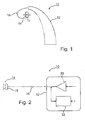
- Fig. 1 shows a schematic view of a hearing device according to the invention.
- the hearing device 10 comprises a first portion 12, a second portion 14 and a coupling element 16.
- the first portion 12 of the shown embodiment is designed to be arranged behind a user's ear, wherein the second portion 14 is designed to be placed inside an ear canal (not shown) of the user.
- the coupling element 16 couples the first portion 12 and the second portion 14 so that a signal generated by the first portion 12 is transmitted to the second portion 14.
- the second portion 14 includes a receiver (or output transducer).
- the shown hearing device 10 is of the RITE type.
- an electrically conducting element (not shown in Fig. 1 ) of the coupling element 16 is used as an antenna for wireless communications to and from the hearing device 10.
- Fig. 2 shows a principal sketch of an electrical diagram illustrating the present invention.
- the first portion 12 of the hearing device 10 comprises a signal processor 20 for generating and/or providing a signal and a wireless interface 22 for exchanging data with an external device (not shown) via an antenna (not shown in Fig. 2 ).
- the hearing device 10 is further provided with an output transducer or receiver 18 as a part of the second portion 14.
- the first and second portion 12, 14, in particular the signal processor 20 and the receiver 18, are coupled by the coupling element 16.
- the signal processor 20 receives an input signal to be processed and outputs or generates a signal to the receiver 18 based on the input signal, wherein the receiver 18 converts the output signal of the signal processor 20 to an acoustic signal which is provided to the user of the hearing device 10.
- matching circuitry for the RF signal and circuitry to separate the RF and the audio signals is preferably included in the hearing instrument.
- Two types of RITE cables with either two or three wires (one or two of the wires typically being used to connect to the receiver) are commonly used. In the first case, with only two balanced wires for the audio signal, both may be used as antenna. In the second case, where an additional shield wire is present, the latter is preferably used.
- Most low power transceivers have a balanced RF I/O, and a balun is preferably provided to transform the balanced RF signal to single ended before it is applied to a diplexer and an antenna matching circuit.
- the diplexer preferably isolates the high frequency contents of the audio signal going to the receiver from the antenna and separates the audio and the RF signal sharing the RITE wires. It is particularly preferable that the diplexer and matching circuitry are highly integrated.
- Figures 3a and 3b show block diagrams illustrating how the transceiver RF signal is isolated from the audio signal and connected to either the shield, in case of three RITE wires, or to both audio wires, if there are only two conductors present, according to a first and second exemplary embodiment of the present invention.
- a low pass filter is provided in series with the audio signal and a high pass filter is provided in series with the RF signal.
- Fig. 3a shows a schematic block diagram of a hearing device according to a first embodiment of the present invention.
- the hearing device 10 comprises a first portion 12, a second portion 14 and a coupling element 16.
- the first portion 12 of the hearing device 10 includes a printed circuit board (PCB) 120 for realizing the primary features of the hearing device 10, e.g. the processing and generation of the signal to be provided to the user, audio signal connections 121, RF signal connections 122, a balun 123, a high-pass filter 124 and a low-pass filter 125.
- the PCB 120 includes a wireless interface (not shown).
- the low-pass filter 125 is coupled to audio signal connections 121 of the PCB 120.
- the balun 123 is coupled to RF-signal connections 122 of the PCB 120.
- the balun 123 is further coupled to a ground connection and to the high-pass filter 124.
- the low-pass filter 125 and the high-pass filter 124 are coupled to wires of the coupling element 16, wherein the high-pass filter 124 is coupled to the electrically conducting element 24 forming the shield wire of the coupling element 16.
- the low-pass filter 125 is coupled to an output transducer 18 provided in the second portion 14.
- the audio signals are passed to the output transducer 18 and converted to an acoustic output, which in turn is supplied to the user.
- RF signals to be sent are converted by the balun 123 and passed through the high-pass filter 124, exciting the antenna including the electrically conducting element 24.
- Fig. 3b shows a schematic block diagram of a hearing device according to a second embodiment of the present invention.
- the second embodiment is similar to the first embodiment.
- the main difference is that there is no shield wire provided in the coupling element 16.
- the high-pass filter 124 is coupled to the wires transmitting the audio signal to the output transducer 18 via respective capacitors 126.
- Fig. 4 shows a schematic block diagram of a hearing device according to a third embodiment of the present invention.
- the output transducer 18 is provided in the first portion 12 of the hearing device 10 of the BTE type.
- the coupling element 16 comprises a tube for forwarding an acoustic signal outputted by the output transducer 18 to the ear of the user, via an ear-mould provided in the second portion 14 of the hearing device 10, which is to be arranged in the ear canal of the user (not shown).
- the balun 123 is coupled to an electrically conducting element 24 of the coupling element 16 acting as an antenna.
- FIGS. 5a and 5b show more detailed schematic block diagrams of a particular implementation according to the first and second embodiment of the present invention shown in Fig. 3a and Fig. 3b .
- the balun 123 is realized in form of a transformer 123, wherein the high-pass filter 124 comprises a capacitor and a inductance coupled in a suitable way.
- the low-pass filter 125 comprises inductances in series with the signal lines and a capacitor coupling the signal lines.
- Fig. 6 shows a flow chart of a method according to the present invention.
- the method for a wireless receiving and/or sending of data in a hearing device according to the present invention comprises the steps of providing (30) an electrically conducting element in said coupling element, arranging (32) said first portion at a user of said hearing device, arranging (34) said second portion in an ear canal of said user, and receiving (36) and/or sending data by means of said electrically conducting element.
- the order of the steps 30 to 34 may be changed.
- a hearing instrument comprises a first body adapted for being positioned behind an ear of a user and a second body adapted for being positioned in an ear canal of a user, and a connecting element mechanically and electrically connecting the first and second bodies, the first body being adapted to provide a processed electrical sound signal intended for being presented to a user via an output transducer and forwarded to the second body via the connecting element, the connecting element comprising at least one electrically conductor, wherein the electrically conductor is adapted to constitute an antenna for a wireless interface of the hearing instrument.
- the second body preferably comprises an output transducer for providing an acoustical signal to a user, wherein the hearing instrument is adapted to transmit the processed electrical sound signal to the output transducer via the at least one electrically conductor of the connecting element.
- the first body comprises an output transducer for providing an acoustical signal to a user, wherein the hearing instrument is adapted to transmit the acoustical signal to an ear canal of the user via the connecting element.
- the hearing instrument as described in the preceding paragraphs preferably further comprises a transmitter for exciting the antenna, the transmitter being connectable to the antenna. It is also found to be advantageous if the antenna is adapted to transmit an RF-signal.
Landscapes
- Engineering & Computer Science (AREA)
- Computer Networks & Wireless Communication (AREA)
- Health & Medical Sciences (AREA)
- General Health & Medical Sciences (AREA)
- Neurosurgery (AREA)
- Otolaryngology (AREA)
- Physics & Mathematics (AREA)
- Acoustics & Sound (AREA)
- Signal Processing (AREA)
- Circuit For Audible Band Transducer (AREA)
- Headphones And Earphones (AREA)
Description
- The present invention is related to a hearing device comprising a first portion adapted for being arranged at a user and for providing a signal, an output transducer for converting said signal to an acoustic output and a second portion adapted for being arranged in an ear canal of said user and for providing said acoustic output to said user. The invention is in particular related to means for a wireless communication to and/or from such a hearing device. The invention is further related to a method for a wireless receiving and/or sending of data in a hearing device and to the use of a hearing device.
- Hearing aids for compensating a wearer's hearing loss are well known. The present invention is particularly related to such kinds of hearing devices. However, the present invention may also be implemented in other types of listening devices, hearing instruments or hearing devices which comprise a connecting element between two physical parts of the device, e.g. a head set, a head phone, ear protection plugs, etc. In the following the terms "hearing device" or "hearing instrument" refer to devices in general which are related to providing an acoustic signal to a user's ear.
- Hearing instruments, in particular hearing aids, are very dense applications and when integrating wireless applications, it may sometimes be difficult to find sufficient space for required or desired antenna components.
- It is widely agreed that an integration of wireless systems into hearing instruments requires integration of antenna structures as well, if bulky external antenna solutions are to be avoided. The efficiency of the antenna and the wireless system is important, as low battery consumption is commonly a design parameter. Various configurations of hearing aids as examples of hearing devices are known, such as in-the-ear (ITE), completely-in-canal (CIC), behind-the-ear (BTE), or receiver-in-the-ear (RITE) hearing aids (the latter sometimes termed 'receiver in the canal').
- The efficiency and bandwidth of antennas for electro-magnetic fields depend strong-ly on the size relative to a wavelength of the signal or field. However, common hearing instruments are typically much smaller than the wavelength in the appropriate frequency bands, which has a disadvantageous effect on the efficiency and bandwidth of the antennas build into the common hearing devices.
-
DE 3625891 A1 deals with a hearing aid comprising a radio transmitting and receiving device including an antenna and a power source accommodated in a housing intended to be worn behind or in the ear. A connecting line is provided for connecting the radio transmitting and receiving device to an electro-acoustic sound transducer located in an otoplasty which contains a sound channel connected to the sound output of the sound transducer. -
WO 2006/055884 A2 deals with a wireless interactive headset. The headset may comprise a wearable support, such as an eyeglass frame, adapted to carry one or more of speakers, microphone and video display, depending upon the desired functionality. In an embodiment an inductive coil may be wrapped helically around a metallic part of an ear stem of the eyeglass frame. In such embodiment, the metallic part of the eye glass frame is excited by the coil and contributes to an improved antenna range or efficiency. -
US 2007/0171134 A1 andEP 1 589 609 A2 deal with ear phone antennas. The use of a balun for converting from a balanced to an unbalanced mode is disclosed. - It is an object of the present invention to provide a hearing device and a method as mentioned above with sufficient characteristics regarding the ability to send and/or receive data in a wireless manner using desired frequencies without a need for additional external antenna solutions or for a size not meeting the current requirements of smallness for hearing devices.
- It is an additional object of the present invention that the above object is achieved with only few modifications to known designs for hearing devices and therefore that the improved hearing device may be based to a large extent on known and well-tested hearing devices without a need for a complex re-design.
- In order to achieve the above objects, the present invention provides a hearing device comprising a first portion adapted for being arranged at a user and for providing a signal, an output transducer for converting said signal to an acoustic output, a second portion adapted for being arranged in an ear canal of said user and for providing said acoustic output to said user, a coupling element coupling said first portion and said second portion, an antenna, and a wireless interface for receiving and/or sending data by means of said antenna, wherein said coupling element comprises an electrically conducting element coupled to said wireless interface, wherein said electrically conducting element is at least a part of said antenna.
- Further, the present invention provides a method for a wireless receiving and/or sending of data in a hearing device comprising a coupling element coupling a first portion and a second portion of said hearing device, the method comprising the steps of providing an electrically conducting element in said coupling element, arranging said first portion at a user of said hearing device, arranging said second portion in an ear canal of said user, and receiving and/or sending data by means of said electrically conducting element.
- In a further aspect, the present invention provides use of a hearing device as defined above, in the description below and in the claims. In an embodiment, use of a hearing aid according to the invention (including the antenna and wireless interface provided by the hearing device) to wirelessly communicate with another communications device is provided. In an embodiment, such other communications device is another hearing device, e.g. the other hearing device of a binaural hearing aid system. In an embodiment, such other communications is an audio gateway, e.g. an audio selection device (cf. e.g.
EP 1 460 769 orWO 2006/117365 A1 ) for wirelessly transmitting an audio signal to the hearing device, the audio signal being selected among a multitude of audio signals, possibly including that from a telephone handset, e.g. a mobile telephone. In an embodiment, the communication between the hearing device and the other communications device is governed by a specific protocol that is adapted to low power applications. - As mentioned above, the present invention relates in particular to hearing instruments of the BTE type and the RITE type, typically comprising a "behind the ear"-part (typically comprising a microphone and a signal processor and one or more - e.g. wireless - communications interfaces) and an "in the ear"-part connected by a connecting element (e.g. a wire or tube). In a RITE-type hearing instrument (comprising a receiver), the connecting element comprises electrically conductors for transferring a processed signal from the "behind the ear"-part of the hearing device to the receiver. In a hearing instrument where the receiver is located in the 'behind the ear' part, the connecting element (e.g. a tube) works as a guide of the acoustical signal from the receiver to the ear canal (e.g. via an ear mould).
- Known hearing instruments with receivers in the ear have conducting wires running at or around the ear to connect the receiver in the ear canal with the other part(s) of the hearing instrument. The present invention is based on the insight that these wires may be used as antenna for a built-in radio transceiver. The invention utilizes the wires, which are already there, as well as the structure of the hearing instrument as radiating elements for the integrated radio transceiver. A similar technique is provided according to the present invention for utilization in BTE (behind the ear) type hearing instruments, wherein - for example - an electrical wire is integrated into the tube connecting the ear mould with the (remainder of the) hearing instrument.
- One or more of the electrically conductors in the RITE cord (or in the interconnecting tube of standard BTE type instruments) may be used as or in an antenna for wireless applications in the hearing instrument. This saves space in the device and reduces cost. Further, as the size of the coupling element allows for a better adaptation to a wavelength of the electromagnetic signal used for transmitting the data, the efficiency and bandwidth of the antenna is improved in comparison to known antenna solutions inside the hearing device.
- No additional mechanical processes are required to manufacture an external or additional antenna structure. Only a few extra standard passive components are needed to implement for example a diplexer to couple the RF signal on to the wire, i.e. to the electrically conducting element.
- It was found that an improvement of efficiency that can be achieved by using the RITE wires compared to an internal loop antenna with an area of maximum 100 mm2 is about 6 dB at 1 GHz, which is a significant improvement from the estimated best case efficiency for the internal loop antenna of -16 dB.
- According to a preferred embodiment of the present invention said second portion includes said output transducer, wherein said coupling element is adapted for transmitting said signal to said output transducer. The output transducer (also termed as "receiver") is provided in the ear of the user at a distance to an input transducer or microphone of the hearing aid, which reduces the risk of acoustic feedback. Further, the transmission of the signal to the output transducer may be achieved by a coupling element of small size since only the (electrical) signal has to be transmitted to the output transducer. Therefore, the coupling element and the hearing device as a whole may be designed to an unobtrusive look. It has to be noted that the output transducer is not necessarily coupled or connected to the electrically conducting element provided in the coupling element.
- According to another embodiment said electrically conducting element is adapted for carrying said signal upon transmission to said output transducer. Here, the same elements or wires are used as part of the antenna and as a transmission means for the signal to be outputted at the same time, which results in a design which is easy and simple to implement.
- In a further embodiment said coupling element comprises two balanced wires for transmitting said signal to said output transducer, wherein said electrically conducting element comprises said wires. The signal transmission wires are used as (at least a part) of the electrically conducting element acting as (at least a part) of the antenna to the wireless interface.
- According to a yet further embodiment, said wireless interface is coupled to said wires via a high-pass filter, wherein said wireless interface is coupled to said high-pass filter via a balun and wherein said high-pass filter is coupled to said wires via respective capacitors, wherein said first portion includes a low-pass filter in the path of said signal. It was found that by such an implementation good results are achievable with very few modifications to a pre-existing hearing device design. In this context it is found to be sufficient that said balun comprises a transformer and that said high-pass filter comprises a capacitor and an inductance. A balun in general is a passive electronic device that converts between balanced and unbalanced electrical signals. The skilled person is well aware of a number of examples of baluns.
- In another embodiment of the present invention said coupling element comprises two wires for transmitting said signal to said output transducer and a shield element for shielding said wires, wherein said electrically conducting element comprises said shield element. As an alternative or in addition to the above options, the shielding of the transmitting wires for the signal to the output transducer are usable as (at least a part of) an antenna.
- According to a further embodiment wherein said wireless interface is coupled to said shield element via a high-pass filter, wherein said wireless interface is coupled to said high-pass filter via a balun, wherein said first portion includes a low-pass filter in the path of said signal. Again, it was found that by such an implementation good results are achievable with very few modifications to a pre-existing hearing device design. Further, it is found to be sufficient in this context as well that said balun comprises a transformer and that said high-pass filter comprises a capacitor and an inductance.
- According to another preferred embodiment of the present invention, said first portion includes said output transducer and wherein said coupling element is provided for transmitting said acoustic output to said second portion. An example of such an arrangement is a BTE type hearing aid, which is among the types of hearing aids which are most commonly used. The acoustic output is generated at the first portion, for example by an output transducer integrated in a behind-the-ear portion of an hearing aid, wherein the acoustic output (signal) is then transmitted or guided by means of the coupling element to the second portion, e.g. an ear mould, and provided to the user in the ear canal. According to a further embodiment of the present invention, said wireless interface is coupled to said electrically conducting element via a balun. According to a yet further embodiment, said coupling element comprises a tube for transmitting said acoustic output to said second portion, in particular a flexible tube.
- In another embodiment of the present invention, said wireless interface is adapted for receiving and/or sending data by means of radio frequency signals, in particular by means of electromagnetic radiation in the frequency range of 1 MHz to 1000 GHz, preferably of 1 MHz to 3 GHz, wherein the wireless interface is most preferably adapted for receiving and/or sending data according to a communications standard, in particular according to Bluetooth.
- According to a further embodiment of the present invention, said first portion is adapted for being arranged behind an ear of said user. If the first portion of the hearing device is arrangable behind an ear of a user, the hearing device may be used in an unobtrusive manner, wherein the first portion is hidden to some extent by the ear.
- As used herein, the singular forms "a," "an," and "the" are intended to include the plural forms as well, unless expressly stated otherwise. It will be further understood that the terms "includes," "comprises," "including," and/or "comprising," when used in this specification, specify the presence of stated features, integers, steps, operations, elements, and/or components, but do not preclude the presence or addition of one or more other features, integers, steps, operations, elements, components, and/or groups thereof. It will be understood that when an element is referred to as being "connected" or "coupled" to another element, it can be directly connected or coupled to the other element or intervening elements maybe present. Furthermore, "connected" or "coupled" as used herein may include wirelessly connected or coupled. As used herein, the term "and/or" includes any and all combinations of one or more of the associated listed items.
- In the following, exemplary embodiments of the present invention are further explained referring to the attached drawings, in which
-
Fig. 1 shows a schematic view of a hearing device according to the invention; -
Fig. 2 shows a principal sketch of an electrical diagram illustrating the present invention; -
Fig. 3a shows a schematic block diagram of a hearing device according to a first embodiment of the present invention; -
Fig. 3b shows a schematic block diagram of a hearing device according to a second embodiment of the present invention; -
Fig. 4 shows a schematic block diagram of a hearing device according to a third embodiment of the present invention; -
Fig. 5a shows a schematic block diagram of a particular implementation accord-ing to the first embodiment of the present invention shown inFig. 3a ; -
Fig. 5b shows a schematic block diagram of a particular implementation accord-ing to the second embodiment of the present invention shown inFig. 3b ;
and -
Fig. 6 shows a flow chart of a method according to the present invention. - The figures are schematic and simplified for clarity, and they just show details which are essential to the understanding of the invention, while other details are left out. Throughout, the same reference numerals are used for identical or corresponding parts.
-
Fig. 1 shows a schematic view of a hearing device according to the invention. Thehearing device 10 comprises afirst portion 12, asecond portion 14 and acoupling element 16. Thefirst portion 12 of the shown embodiment is designed to be arranged behind a user's ear, wherein thesecond portion 14 is designed to be placed inside an ear canal (not shown) of the user. Thecoupling element 16 couples thefirst portion 12 and thesecond portion 14 so that a signal generated by thefirst portion 12 is transmitted to thesecond portion 14. According to the shown implementation thesecond portion 14 includes a receiver (or output transducer). Accordingly, the shown hearingdevice 10 is of the RITE type. According to the present invention, an electrically conducting element (not shown inFig. 1 ) of thecoupling element 16 is used as an antenna for wireless communications to and from thehearing device 10. -
Fig. 2 shows a principal sketch of an electrical diagram illustrating the present invention. Thefirst portion 12 of thehearing device 10 comprises asignal processor 20 for generating and/or providing a signal and awireless interface 22 for exchanging data with an external device (not shown) via an antenna (not shown inFig. 2 ). Thehearing device 10 is further provided with an output transducer orreceiver 18 as a part of thesecond portion 14. The first andsecond portion signal processor 20 and thereceiver 18, are coupled by thecoupling element 16. Thesignal processor 20 receives an input signal to be processed and outputs or generates a signal to thereceiver 18 based on the input signal, wherein thereceiver 18 converts the output signal of thesignal processor 20 to an acoustic signal which is provided to the user of thehearing device 10. - In order to use the RITE wires as an antenna, matching circuitry for the RF signal and circuitry to separate the RF and the audio signals is preferably included in the hearing instrument. Two types of RITE cables with either two or three wires (one or two of the wires typically being used to connect to the receiver) are commonly used. In the first case, with only two balanced wires for the audio signal, both may be used as antenna. In the second case, where an additional shield wire is present, the latter is preferably used.
- Most low power transceivers have a balanced RF I/O, and a balun is preferably provided to transform the balanced RF signal to single ended before it is applied to a diplexer and an antenna matching circuit. The diplexer preferably isolates the high frequency contents of the audio signal going to the receiver from the antenna and separates the audio and the RF signal sharing the RITE wires. It is particularly preferable that the diplexer and matching circuitry are highly integrated.
-
Figures 3a and 3b show block diagrams illustrating how the transceiver RF signal is isolated from the audio signal and connected to either the shield, in case of three RITE wires, or to both audio wires, if there are only two conductors present, according to a first and second exemplary embodiment of the present invention. A low pass filter is provided in series with the audio signal and a high pass filter is provided in series with the RF signal. -
Fig. 3a shows a schematic block diagram of a hearing device according to a first embodiment of the present invention. Thehearing device 10 comprises afirst portion 12, asecond portion 14 and acoupling element 16. Thefirst portion 12 of thehearing device 10 includes a printed circuit board (PCB) 120 for realizing the primary features of thehearing device 10, e.g. the processing and generation of the signal to be provided to the user,audio signal connections 121,RF signal connections 122, abalun 123, a high-pass filter 124 and a low-pass filter 125. Further, thePCB 120 includes a wireless interface (not shown). The low-pass filter 125 is coupled toaudio signal connections 121 of thePCB 120. Thebalun 123 is coupled to RF-signal connections 122 of thePCB 120. Thebalun 123 is further coupled to a ground connection and to the high-pass filter 124. The low-pass filter 125 and the high-pass filter 124 are coupled to wires of thecoupling element 16, wherein the high-pass filter 124 is coupled to the electrically conductingelement 24 forming the shield wire of thecoupling element 16. The low-pass filter 125 is coupled to anoutput transducer 18 provided in thesecond portion 14. The audio signals are passed to theoutput transducer 18 and converted to an acoustic output, which in turn is supplied to the user. RF signals to be sent are converted by thebalun 123 and passed through the high-pass filter 124, exciting the antenna including the electrically conductingelement 24. In case the antenna or electrically conductingelement 24 is excited by external RF signals arriving at said hearing device, these external RF signals are passed through the high-pass filter 124 and thebalun 123 to enter thePCB 120 at theRF signal connections 122, where the external signals are received by the wireless interface (not shown). -
Fig. 3b shows a schematic block diagram of a hearing device according to a second embodiment of the present invention. The second embodiment is similar to the first embodiment. The main difference is that there is no shield wire provided in thecoupling element 16. Instead of being coupled to the shield wire as shown inFig. 3a , the high-pass filter 124 is coupled to the wires transmitting the audio signal to theoutput transducer 18 viarespective capacitors 126. -
Fig. 4 shows a schematic block diagram of a hearing device according to a third embodiment of the present invention. Rather than providing the output transducer orreceiver 18 in thesecond portion 14 and in the ear of the user as in the case of the first and second embodiment shown inFigs. 3a and 3b , theoutput transducer 18 is provided in thefirst portion 12 of thehearing device 10 of the BTE type. Thecoupling element 16 comprises a tube for forwarding an acoustic signal outputted by theoutput transducer 18 to the ear of the user, via an ear-mould provided in thesecond portion 14 of thehearing device 10, which is to be arranged in the ear canal of the user (not shown). Thebalun 123 is coupled to an electrically conductingelement 24 of thecoupling element 16 acting as an antenna. -
Figures 5a and 5b show more detailed schematic block diagrams of a particular implementation according to the first and second embodiment of the present invention shown inFig. 3a and Fig. 3b . Thebalun 123 is realized in form of atransformer 123, wherein the high-pass filter 124 comprises a capacitor and a inductance coupled in a suitable way. The low-pass filter 125 comprises inductances in series with the signal lines and a capacitor coupling the signal lines. -
Fig. 6 shows a flow chart of a method according to the present invention. The method for a wireless receiving and/or sending of data in a hearing device according to the present invention comprises the steps of providing (30) an electrically conducting element in said coupling element, arranging (32) said first portion at a user of said hearing device, arranging (34) said second portion in an ear canal of said user, and receiving (36) and/or sending data by means of said electrically conducting element. The order of thesteps 30 to 34 may be changed. - According to a further preferred aspect of the present invention a hearing instrument comprises a first body adapted for being positioned behind an ear of a user and a second body adapted for being positioned in an ear canal of a user, and a connecting element mechanically and electrically connecting the first and second bodies, the first body being adapted to provide a processed electrical sound signal intended for being presented to a user via an output transducer and forwarded to the second body via the connecting element, the connecting element comprising at least one electrically conductor, wherein the electrically conductor is adapted to constitute an antenna for a wireless interface of the hearing instrument.
- In a hearing instrument according to the above aspect the second body preferably comprises an output transducer for providing an acoustical signal to a user, wherein the hearing instrument is adapted to transmit the processed electrical sound signal to the output transducer via the at least one electrically conductor of the connecting element.
- Additionally or alternatively to the implementation described in the previous paragraph the first body comprises an output transducer for providing an acoustical signal to a user, wherein the hearing instrument is adapted to transmit the acoustical signal to an ear canal of the user via the connecting element.
- The hearing instrument as described in the preceding paragraphs preferably further comprises a transmitter for exciting the antenna, the transmitter being connectable to the antenna. It is also found to be advantageous if the antenna is adapted to transmit an RF-signal.
- The invention is defined by the features of the independent claim(s). Preferred embodiments are defined in the dependent claims. Any reference numerals in the claims are intended to be non-limiting for their scope.
- Some preferred embodiments have been shown in the foregoing, but it should be stressed that the invention is not limited to these, but may be embodied in other ways within the subject-matter defined in the following claims.
Claims (12)
- A hearing device (10) comprising:- a first portion (12) adapted for being arranged at a user and for providing a signal,- an output transducer (18) for converting said signal to an acoustic output,- a second portion (14) adapted for being arranged in an ear canal of said user and for providing said acoustic output to said user, wherein said second portion (14) includes said output transducer (18),- a coupling element (16) coupling said first portion (12) and said second portion (14), and wherein said coupling element (16) is adapted for transmitting said signal to said output transducer (18),- an antenna, and- a wireless interface (22) for receiving and/or sending data by means of said antenna,wherein said coupling element (16) comprises an electrically conducting element (24) coupled to said wireless interface (22), wherein said electrically conducting element (24) is at least a part of said antenna, and wherein said electrically conducting element (24) is adapted for carrying said signal upon transmission to said output transducer (18).
- The hearing device (10) according to claim 1,
wherein said coupling element (16) comprises two balanced wires for transmitting said signal to said output transducer (18), wherein said electrically conducting element (24) comprises said wires. - The hearing device (10) according to claim 2,
wherein said wireless interface (22) is coupled to said wires via a high-pass filter (124), wherein said wireless interface (22) is coupled to said high-pass filter (124) via a balun (123) and wherein said high-pass filter (124) is coupled to said wires via respective capacitors (126), wherein said first portion (12) includes a low-pass filter (125) in the path of said signal. - The hearing device (10) according to claim 3,
wherein said balun (123) comprises a transformer and wherein said high-pass filter (124) comprises a capacitor and an inductance. - The hearing device (10) according to any one of claims 1-4,
wherein said coupling element (16) comprises two wires for transmitting said signal to said output transducer (18) and a shield element for shielding said wires, wherein said electrically conducting element (24) comprises said shield element. - The hearing device (10) according to claim 5,
wherein said wireless interface (22) is coupled to said shield element via a high-pass filter (124), wherein said wireless interface (22) is coupled to said high-pass filter (124) via a balun (123), wherein said first portion (12) includes a low-pass filter (125) in the path of said signal. - The hearing device (10) according to claim 6,
wherein said balun (123) comprises a transformer and wherein said high-pass filter (124) comprises a capacitor and an inductance. - The hearing device (10) according to any one of the preceding claims,
wherein said wireless interface (22) is adapted for receiving and/or sending data by means of radio frequency signals, in particular by means of electromagnetic radiation in the frequency range of 1 MHz to 1000 GHz, preferably of 1 MHz to 3 GHz, wherein the wireless interface is most preferably adapted for receiving and/or sending data according to a communications standard, in particular according to Bluetooth. - The hearing device (10) according to any one of the preceding claims,
wherein said first portion (12) is adapted for being arranged behind an ear of said user. - A method for a wireless receiving and/or sending of data in a hearing device (10) comprising a coupling element (16) coupling a first portion (12) and a second portion (14) of said hearing device (10), the first portion providing an electric signal and the second portion comprising an output transducer (18) for converting said electric signal to an acoustic output, the method comprising the steps of:- providing (30) an electrically conducting element (24) in said coupling element (16),- arranging (32) said first portion (12) at a user of said hearing device,- arranging (34) said second portion (14) in an ear canal of said user, and- receiving and/or sending data (36) by means of said electrically conducting element (24), and- arranging that said coupling element (16) transmits said electric signal to said output transducer (18).
- Use of a hearing device according to any one of claims 1-9.
- Use according to claim 11 to wirelessly communicate with another communications device, e.g. another hearing device, e.g. the other hearing device of a binaural hearing aid system and/or with an audio gateway.
Priority Applications (7)
| Application Number | Priority Date | Filing Date | Title |
|---|---|---|---|
| EP07124109.5A EP2076065B2 (en) | 2007-12-27 | 2007-12-27 | Hearing device and method for a wireless receiving and/or sending of data |
| ES07124109.5T ES2443918T5 (en) | 2007-12-27 | 2007-12-27 | Hearing device and procedure for receiving and / or sending wireless data |
| DK07124109.5T DK2076065T4 (en) | 2007-12-27 | 2007-12-27 | Hearing aid and method for wireless reception and / or transmission of data |
| US12/342,241 US8300863B2 (en) | 2007-12-27 | 2008-12-23 | Hearing device and method for a wireless receiving and/or sending of data |
| CNA2008101873527A CN101489171A (en) | 2007-12-27 | 2008-12-29 | Hearing device and method for a wireless receiving and/or sending of data |
| CN201611107140.4A CN106878901A (en) | 2007-12-27 | 2008-12-29 | Hearing devices and wireless receiving and/or the method for sending data |
| DKBA201300096U DK201300096Y6 (en) | 2007-12-27 | 2013-06-13 | Hearing aid for receiving and / or transmitting data wirelessly |
Applications Claiming Priority (1)
| Application Number | Priority Date | Filing Date | Title |
|---|---|---|---|
| EP07124109.5A EP2076065B2 (en) | 2007-12-27 | 2007-12-27 | Hearing device and method for a wireless receiving and/or sending of data |
Publications (3)
| Publication Number | Publication Date |
|---|---|
| EP2076065A1 EP2076065A1 (en) | 2009-07-01 |
| EP2076065B1 true EP2076065B1 (en) | 2014-01-22 |
| EP2076065B2 EP2076065B2 (en) | 2016-11-16 |
Family
ID=39272459
Family Applications (1)
| Application Number | Title | Priority Date | Filing Date |
|---|---|---|---|
| EP07124109.5A Active EP2076065B2 (en) | 2007-12-27 | 2007-12-27 | Hearing device and method for a wireless receiving and/or sending of data |
Country Status (5)
| Country | Link |
|---|---|
| US (1) | US8300863B2 (en) |
| EP (1) | EP2076065B2 (en) |
| CN (2) | CN106878901A (en) |
| DK (2) | DK2076065T4 (en) |
| ES (1) | ES2443918T5 (en) |
Cited By (1)
| Publication number | Priority date | Publication date | Assignee | Title |
|---|---|---|---|---|
| US9883296B2 (en) | 2014-12-03 | 2018-01-30 | Starkey Laboratories, Inc. | Filter to suppress harmonics for an antenna |
Families Citing this family (56)
| Publication number | Priority date | Publication date | Assignee | Title |
|---|---|---|---|---|
| US8934984B2 (en) | 2007-05-31 | 2015-01-13 | Cochlear Limited | Behind-the-ear (BTE) prosthetic device with antenna |
| DK2208367T3 (en) | 2007-10-12 | 2017-11-13 | Earlens Corp | Multifunction system and method for integrated listening and communication with noise cancellation and feedback management |
| US8867765B2 (en) | 2008-02-06 | 2014-10-21 | Starkey Laboratories, Inc. | Antenna used in conjunction with the conductors for an audio transducer |
| US9295848B2 (en) | 2008-03-28 | 2016-03-29 | Cochlear Limited | Antenna for behind-the-ear (BTE) devices |
| US8514662B2 (en) * | 2010-08-27 | 2013-08-20 | Verifone Systems, Inc. | Sonic receiver and method for receiving data that uses modulation frequncies that reduce the probability of conflict with ambient noise in the environment |
| EP2725655B1 (en) | 2010-10-12 | 2021-07-07 | GN Hearing A/S | A behind-the-ear hearing aid with an improved antenna |
| EP2628210B1 (en) | 2010-10-12 | 2019-01-09 | GN Hearing A/S | A hearing aid comprising an antenna device |
| US8837257B2 (en) | 2010-11-29 | 2014-09-16 | Verifone Systems, Incorporated | Acoustic modulation protocol |
| DK2656639T3 (en) | 2010-12-20 | 2020-06-29 | Earlens Corp | Anatomically adapted ear canal hearing aid |
| EP2605492A1 (en) | 2011-12-15 | 2013-06-19 | Oticon A/s | Mobile bluetooth device |
| US9319807B2 (en) | 2012-02-28 | 2016-04-19 | Cochlear Limited | Device with combined antenna and transducer |
| DK201270410A (en) | 2012-07-06 | 2014-01-07 | Gn Resound As | BTE hearing aid with an antenna partition plane |
| US9554219B2 (en) | 2012-07-06 | 2017-01-24 | Gn Resound A/S | BTE hearing aid having a balanced antenna |
| TWM448100U (en) * | 2012-09-26 | 2013-03-01 | Dexin Corp | Bluetooth headset |
| WO2014086392A1 (en) * | 2012-12-04 | 2014-06-12 | Phonak Ag | Hearing instrument comprising two antennas |
| US9237404B2 (en) * | 2012-12-28 | 2016-01-12 | Gn Resound A/S | Dipole antenna for a hearing aid |
| DK2750409T3 (en) | 2012-12-28 | 2020-05-18 | Gn Hearing As | Dipole antenna for a hearing aid |
| EP2835863B1 (en) | 2013-08-09 | 2019-12-11 | Oticon A/s | Hearing device with RF antenna |
| US9883295B2 (en) | 2013-11-11 | 2018-01-30 | Gn Hearing A/S | Hearing aid with an antenna |
| US9408003B2 (en) | 2013-11-11 | 2016-08-02 | Gn Resound A/S | Hearing aid with an antenna |
| US9686621B2 (en) | 2013-11-11 | 2017-06-20 | Gn Hearing A/S | Hearing aid with an antenna |
| EP3422742B1 (en) | 2014-02-17 | 2021-05-26 | GN Hearing A/S | Hearing aid configuration detection |
| WO2015127973A1 (en) * | 2014-02-27 | 2015-09-03 | Sonova Ag | Hearing instrument comprising an rf antenna |
| WO2015127972A1 (en) * | 2014-02-27 | 2015-09-03 | Sonova Ag | Hearing instrument comprising an rf antenna |
| US10034103B2 (en) | 2014-03-18 | 2018-07-24 | Earlens Corporation | High fidelity and reduced feedback contact hearing apparatus and methods |
| EP2942979B1 (en) * | 2014-05-07 | 2018-09-12 | Jay Rabel | Increasing antenna performance for wireless hearing assistance devices |
| WO2016011044A1 (en) | 2014-07-14 | 2016-01-21 | Earlens Corporation | Sliding bias and peak limiting for optical hearing devices |
| US10595138B2 (en) | 2014-08-15 | 2020-03-17 | Gn Hearing A/S | Hearing aid with an antenna |
| US9307317B2 (en) | 2014-08-29 | 2016-04-05 | Coban Technologies, Inc. | Wireless programmable microphone apparatus and system for integrated surveillance system devices |
| US9225527B1 (en) | 2014-08-29 | 2015-12-29 | Coban Technologies, Inc. | Hidden plug-in storage drive for data integrity |
| US9924276B2 (en) | 2014-11-26 | 2018-03-20 | Earlens Corporation | Adjustable venting for hearing instruments |
| CN104856689A (en) * | 2015-06-01 | 2015-08-26 | 徐州智康信息科技有限公司 | Intelligent hearing detection device |
| DK3103511T3 (en) * | 2015-06-11 | 2019-06-03 | Oticon As | COCHLEAR HEARING DEVICE WITH CABLE ANTENNA |
| US9661426B2 (en) | 2015-06-22 | 2017-05-23 | Gn Hearing A/S | Hearing aid having combined antennas |
| EP3116238B1 (en) * | 2015-07-08 | 2020-01-29 | Oticon A/s | Spacer and hearing device comprising it |
| US11350226B2 (en) | 2015-12-30 | 2022-05-31 | Earlens Corporation | Charging protocol for rechargeable hearing systems |
| US20170195806A1 (en) | 2015-12-30 | 2017-07-06 | Earlens Corporation | Battery coating for rechargable hearing systems |
| US10165171B2 (en) | 2016-01-22 | 2018-12-25 | Coban Technologies, Inc. | Systems, apparatuses, and methods for controlling audiovisual apparatuses |
| US10152858B2 (en) | 2016-05-09 | 2018-12-11 | Coban Technologies, Inc. | Systems, apparatuses and methods for triggering actions based on data capture and characterization |
| US10789840B2 (en) | 2016-05-09 | 2020-09-29 | Coban Technologies, Inc. | Systems, apparatuses and methods for detecting driving behavior and triggering actions based on detected driving behavior |
| US10370102B2 (en) | 2016-05-09 | 2019-08-06 | Coban Technologies, Inc. | Systems, apparatuses and methods for unmanned aerial vehicle |
| WO2018048794A1 (en) * | 2016-09-09 | 2018-03-15 | Earlens Corporation | Contact hearing systems, apparatus and methods |
| WO2018093733A1 (en) | 2016-11-15 | 2018-05-24 | Earlens Corporation | Improved impression procedure |
| EP3343953B1 (en) | 2016-12-29 | 2022-07-06 | Oticon A/s | A hearing device including an external antenna and an internal parasitic element |
| DK3343954T3 (en) | 2016-12-29 | 2023-07-03 | Oticon As | HEARING DEVICE INCLUDING AN EXTERNAL ANTENNA PART AND AN INTERNAL ANTENNA PART |
| US10582317B2 (en) | 2016-12-29 | 2020-03-03 | Oticon A/S | Hearing device including an external antenna part and an internal antenna part |
| DK3343955T3 (en) | 2016-12-29 | 2022-08-29 | Oticon As | Anordning til et høreapparat |
| US10848853B2 (en) * | 2017-06-23 | 2020-11-24 | Energous Corporation | Systems, methods, and devices for utilizing a wire of a sound-producing device as an antenna for receipt of wirelessly delivered power |
| EP3506657B1 (en) | 2017-12-29 | 2021-09-15 | GN Hearing A/S | Hearing instrument comprising a battery antenna and method of operating thereof. |
| DK3506656T3 (en) | 2017-12-29 | 2023-05-01 | Gn Hearing As | HEARING INSTRUMENT COMPRISING A PARASITIC BATTERY ANTENNA ELEMENT |
| WO2019173470A1 (en) | 2018-03-07 | 2019-09-12 | Earlens Corporation | Contact hearing device and retention structure materials |
| WO2019199680A1 (en) | 2018-04-09 | 2019-10-17 | Earlens Corporation | Dynamic filter |
| US11122376B2 (en) * | 2019-04-01 | 2021-09-14 | Starkey Laboratories, Inc. | Ear-worn electronic device incorporating magnetically coupled feed for an antenna |
| EP3886462A1 (en) * | 2020-03-28 | 2021-09-29 | GN Hearing A/S | A hearing device |
| DE102021200195B4 (en) * | 2021-01-12 | 2024-02-22 | Sivantos Pte. Ltd. | hearing aid |
| US11627420B2 (en) | 2021-05-14 | 2023-04-11 | Bose Corporation | Loop antenna for hearing aid |
Family Cites Families (25)
| Publication number | Priority date | Publication date | Assignee | Title |
|---|---|---|---|---|
| US2535063A (en) † | 1945-05-03 | 1950-12-26 | Farnsworth Res Corp | Communicating system |
| DE3625891A1 (en) | 1986-07-31 | 1988-02-04 | Bosch Gmbh Robert | Audible sound transmission system |
| US6021207A (en) * | 1997-04-03 | 2000-02-01 | Resound Corporation | Wireless open ear canal earpiece |
| US20020091337A1 (en) † | 2000-02-07 | 2002-07-11 | Adams Theodore P. | Wireless communications system for implantable hearing aid |
| DE10115896C2 (en) * | 2001-03-30 | 2003-12-24 | Siemens Audiologische Technik | Transmitter and / or receiver unit, which can be releasably connected to a hearing aid, and a programmable hearing aid |
| EP1428410A2 (en) † | 2001-09-17 | 2004-06-16 | Roke Manor Research Limited | A headphone |
| DE10236940B3 (en) * | 2002-08-12 | 2004-02-19 | Siemens Audiologische Technik Gmbh | Space-saving antenna arrangement for hearing aids |
| DE10245555A1 (en) * | 2002-09-30 | 2004-04-15 | Siemens Audiologische Technik Gmbh | Wireless transmission system for hearing aids |
| JP4363865B2 (en) † | 2003-02-28 | 2009-11-11 | ソニー株式会社 | Earphone antenna and radio |
| JP4003671B2 (en) | 2003-03-07 | 2007-11-07 | ソニー株式会社 | Earphone antenna and radio equipped with the same |
| WO2004110099A2 (en) † | 2003-06-06 | 2004-12-16 | Gn Resound A/S | A hearing aid wireless network |
| US7532733B2 (en) * | 2003-06-30 | 2009-05-12 | Siemens Hearing Instruments, Inc. | Feedback reducing receiver mount and assembly |
| JP3880571B2 (en) † | 2003-10-29 | 2007-02-14 | Necアクセステクニカ株式会社 | Antenna device |
| DK1716723T3 (en) † | 2004-02-08 | 2009-02-16 | Widex As | Output stage for hearing aid and method for operating an output stage |
| DK1719384T3 (en) * | 2004-02-19 | 2011-07-11 | Oticon As | Hearing aid with antenna for receiving and transmitting electromagnetic signals and shielding battery |
| DE102004017832B3 (en) * | 2004-04-13 | 2005-10-20 | Siemens Audiologische Technik | hearing Aid |
| JP4026648B2 (en) * | 2004-04-19 | 2007-12-26 | ソニー株式会社 | Earphone antenna and portable radio equipped with the earphone antenna |
| JP2006025392A (en) † | 2004-06-11 | 2006-01-26 | Matsushita Electric Ind Co Ltd | Earphone cable antenna device, connection cable, and broadcast receiving apparatus |
| KR101231026B1 (en) | 2004-11-19 | 2013-02-07 | 오우크리이, 인크. | Wireless interactive headset |
| DE102005046169A1 (en) * | 2005-09-27 | 2007-04-05 | Siemens Audiologische Technik Gmbh | Hearing aid with an antenna |
| JP4123262B2 (en) * | 2005-10-07 | 2008-07-23 | ソニー株式会社 | Earphone antenna |
| EP1821571A1 (en) * | 2006-02-15 | 2007-08-22 | Oticon A/S | Loop antenna for in the ear audio device |
| US8027638B2 (en) * | 2006-03-29 | 2011-09-27 | Micro Ear Technology, Inc. | Wireless communication system using custom earmold |
| DE112007001275T5 (en) † | 2006-05-30 | 2009-04-23 | Knowles Electronics, LLC, Itasca | personal listening |
| US20090069060A1 (en) * | 2007-09-11 | 2009-03-12 | Kim Young S | Clip-on wireless device with retractable ear piece |
-
2007
- 2007-12-27 ES ES07124109.5T patent/ES2443918T5/en active Active
- 2007-12-27 DK DK07124109.5T patent/DK2076065T4/en active
- 2007-12-27 EP EP07124109.5A patent/EP2076065B2/en active Active
-
2008
- 2008-12-23 US US12/342,241 patent/US8300863B2/en active Active
- 2008-12-29 CN CN201611107140.4A patent/CN106878901A/en active Pending
- 2008-12-29 CN CNA2008101873527A patent/CN101489171A/en active Pending
-
2013
- 2013-06-13 DK DKBA201300096U patent/DK201300096Y6/en not_active IP Right Cessation
Cited By (1)
| Publication number | Priority date | Publication date | Assignee | Title |
|---|---|---|---|---|
| US9883296B2 (en) | 2014-12-03 | 2018-01-30 | Starkey Laboratories, Inc. | Filter to suppress harmonics for an antenna |
Also Published As
| Publication number | Publication date |
|---|---|
| CN106878901A (en) | 2017-06-20 |
| DK201300096U1 (en) | 2013-06-28 |
| DK2076065T4 (en) | 2017-02-20 |
| ES2443918T5 (en) | 2017-06-06 |
| EP2076065B2 (en) | 2016-11-16 |
| DK2076065T3 (en) | 2014-02-03 |
| US8300863B2 (en) | 2012-10-30 |
| ES2443918T3 (en) | 2014-02-21 |
| EP2076065A1 (en) | 2009-07-01 |
| DK201300096U3 (en) | 2013-09-13 |
| DK201300096Y6 (en) | 2014-08-08 |
| US20090169038A1 (en) | 2009-07-02 |
| CN101489171A (en) | 2009-07-22 |
Similar Documents
| Publication | Publication Date | Title |
|---|---|---|
| EP2076065B1 (en) | Hearing device and method for a wireless receiving and/or sending of data | |
| US11653157B2 (en) | Antenna used in conjunction with the conductors for an audio transducer | |
| US9237404B2 (en) | Dipole antenna for a hearing aid | |
| EP3110171B1 (en) | Hearing aid bowtie antenna optimized for ear to ear communications | |
| EP2750409B1 (en) | A dipole antenna for a hearing aid | |
| CN113852900B (en) | Hearing device | |
| US10667065B2 (en) | Hearing instrument having an antenna system | |
| WO2015127972A1 (en) | Hearing instrument comprising an rf antenna | |
| CN108289274B (en) | Hearing device comprising an external antenna and an internal parasitic element | |
| US11778394B2 (en) | Hearing device with an antenna | |
| EP3506657A1 (en) | A hearing instrument comprising a battery antenna | |
| EP3506656B1 (en) | A hearing instrument comprising a parasitic battery antenna element | |
| JP2020048197A (en) | Hearing device having antenna function in support structure | |
| CN110691313A (en) | Hearing device comprising an outer antenna part and an inner antenna part | |
| EP4057639A1 (en) | Hearing device comprising a module | |
| US20230388726A1 (en) | Hearing device having a multi-feed antenna apparatus and multi-feed antenna apparatus | |
| EP3598776A1 (en) | Multi-frequency separation |
Legal Events
| Date | Code | Title | Description |
|---|---|---|---|
| PUAI | Public reference made under article 153(3) epc to a published international application that has entered the european phase |
Free format text: ORIGINAL CODE: 0009012 |
|
| AK | Designated contracting states |
Kind code of ref document: A1 Designated state(s): AT BE BG CH CY CZ DE DK EE ES FI FR GB GR HU IE IS IT LI LT LU LV MC MT NL PL PT RO SE SI SK TR |
|
| AX | Request for extension of the european patent |
Extension state: AL BA HR MK RS |
|
| 17P | Request for examination filed |
Effective date: 20090707 |
|
| 17Q | First examination report despatched |
Effective date: 20090731 |
|
| AKX | Designation fees paid |
Designated state(s): AT BE BG CH CY CZ DE DK EE ES FI FR GB GR HU IE IS IT LI LT LU LV MC MT NL PL PT RO SE SI SK TR |
|
| GRAP | Despatch of communication of intention to grant a patent |
Free format text: ORIGINAL CODE: EPIDOSNIGR1 |
|
| INTG | Intention to grant announced |
Effective date: 20130725 |
|
| GRAS | Grant fee paid |
Free format text: ORIGINAL CODE: EPIDOSNIGR3 |
|
| GRAA | (expected) grant |
Free format text: ORIGINAL CODE: 0009210 |
|
| AK | Designated contracting states |
Kind code of ref document: B1 Designated state(s): AT BE BG CH CY CZ DE DK EE ES FI FR GB GR HU IE IS IT LI LT LU LV MC MT NL PL PT RO SE SI SK TR |
|
| REG | Reference to a national code |
Ref country code: GB Ref legal event code: FG4D |
|
| REG | Reference to a national code |
Ref country code: CH Ref legal event code: EP |
|
| REG | Reference to a national code |
Ref country code: DK Ref legal event code: T3 Effective date: 20140131 |
|
| REG | Reference to a national code |
Ref country code: AT Ref legal event code: REF Ref document number: 651248 Country of ref document: AT Kind code of ref document: T Effective date: 20140215 |
|
| REG | Reference to a national code |
Ref country code: ES Ref legal event code: FG2A Ref document number: 2443918 Country of ref document: ES Kind code of ref document: T3 Effective date: 20140221 |
|
| REG | Reference to a national code |
Ref country code: IE Ref legal event code: FG4D |
|
| REG | Reference to a national code |
Ref country code: DE Ref legal event code: R096 Ref document number: 602007034883 Country of ref document: DE Effective date: 20140306 |
|
| REG | Reference to a national code |
Ref country code: NL Ref legal event code: T3 |
|
| PLBI | Opposition filed |
Free format text: ORIGINAL CODE: 0009260 |
|
| 26 | Opposition filed |
Opponent name: GN RESOUND A/S Effective date: 20140429 |
|
| REG | Reference to a national code |
Ref country code: AT Ref legal event code: MK05 Ref document number: 651248 Country of ref document: AT Kind code of ref document: T Effective date: 20140122 |
|
| REG | Reference to a national code |
Ref country code: LT Ref legal event code: MG4D |
|
| REG | Reference to a national code |
Ref country code: DE Ref legal event code: R026 Ref document number: 602007034883 Country of ref document: DE Effective date: 20140429 |
|
| PG25 | Lapsed in a contracting state [announced via postgrant information from national office to epo] |
Ref country code: LT Free format text: LAPSE BECAUSE OF FAILURE TO SUBMIT A TRANSLATION OF THE DESCRIPTION OR TO PAY THE FEE WITHIN THE PRESCRIBED TIME-LIMIT Effective date: 20140122 Ref country code: IS Free format text: LAPSE BECAUSE OF FAILURE TO SUBMIT A TRANSLATION OF THE DESCRIPTION OR TO PAY THE FEE WITHIN THE PRESCRIBED TIME-LIMIT Effective date: 20140522 |
|
| PG25 | Lapsed in a contracting state [announced via postgrant information from national office to epo] |
Ref country code: PT Free format text: LAPSE BECAUSE OF FAILURE TO SUBMIT A TRANSLATION OF THE DESCRIPTION OR TO PAY THE FEE WITHIN THE PRESCRIBED TIME-LIMIT Effective date: 20140522 Ref country code: AT Free format text: LAPSE BECAUSE OF FAILURE TO SUBMIT A TRANSLATION OF THE DESCRIPTION OR TO PAY THE FEE WITHIN THE PRESCRIBED TIME-LIMIT Effective date: 20140122 Ref country code: FI Free format text: LAPSE BECAUSE OF FAILURE TO SUBMIT A TRANSLATION OF THE DESCRIPTION OR TO PAY THE FEE WITHIN THE PRESCRIBED TIME-LIMIT Effective date: 20140122 Ref country code: CY Free format text: LAPSE BECAUSE OF FAILURE TO SUBMIT A TRANSLATION OF THE DESCRIPTION OR TO PAY THE FEE WITHIN THE PRESCRIBED TIME-LIMIT Effective date: 20140122 Ref country code: SE Free format text: LAPSE BECAUSE OF FAILURE TO SUBMIT A TRANSLATION OF THE DESCRIPTION OR TO PAY THE FEE WITHIN THE PRESCRIBED TIME-LIMIT Effective date: 20140122 |
|
| PG25 | Lapsed in a contracting state [announced via postgrant information from national office to epo] |
Ref country code: BE Free format text: LAPSE BECAUSE OF FAILURE TO SUBMIT A TRANSLATION OF THE DESCRIPTION OR TO PAY THE FEE WITHIN THE PRESCRIBED TIME-LIMIT Effective date: 20140122 Ref country code: LV Free format text: LAPSE BECAUSE OF FAILURE TO SUBMIT A TRANSLATION OF THE DESCRIPTION OR TO PAY THE FEE WITHIN THE PRESCRIBED TIME-LIMIT Effective date: 20140122 |
|
| PG25 | Lapsed in a contracting state [announced via postgrant information from national office to epo] |
Ref country code: RO Free format text: LAPSE BECAUSE OF FAILURE TO SUBMIT A TRANSLATION OF THE DESCRIPTION OR TO PAY THE FEE WITHIN THE PRESCRIBED TIME-LIMIT Effective date: 20140122 Ref country code: CZ Free format text: LAPSE BECAUSE OF FAILURE TO SUBMIT A TRANSLATION OF THE DESCRIPTION OR TO PAY THE FEE WITHIN THE PRESCRIBED TIME-LIMIT Effective date: 20140122 Ref country code: EE Free format text: LAPSE BECAUSE OF FAILURE TO SUBMIT A TRANSLATION OF THE DESCRIPTION OR TO PAY THE FEE WITHIN THE PRESCRIBED TIME-LIMIT Effective date: 20140122 |
|
| PG25 | Lapsed in a contracting state [announced via postgrant information from national office to epo] |
Ref country code: PL Free format text: LAPSE BECAUSE OF FAILURE TO SUBMIT A TRANSLATION OF THE DESCRIPTION OR TO PAY THE FEE WITHIN THE PRESCRIBED TIME-LIMIT Effective date: 20140122 Ref country code: SK Free format text: LAPSE BECAUSE OF FAILURE TO SUBMIT A TRANSLATION OF THE DESCRIPTION OR TO PAY THE FEE WITHIN THE PRESCRIBED TIME-LIMIT Effective date: 20140122 |
|
| PLAX | Notice of opposition and request to file observation + time limit sent |
Free format text: ORIGINAL CODE: EPIDOSNOBS2 |
|
| PLAB | Opposition data, opponent's data or that of the opponent's representative modified |
Free format text: ORIGINAL CODE: 0009299OPPO |
|
| PLBB | Reply of patent proprietor to notice(s) of opposition received |
Free format text: ORIGINAL CODE: EPIDOSNOBS3 |
|
| R26 | Opposition filed (corrected) |
Opponent name: GN RESOUND A/S Effective date: 20140429 |
|
| PG25 | Lapsed in a contracting state [announced via postgrant information from national office to epo] |
Ref country code: SI Free format text: LAPSE BECAUSE OF FAILURE TO SUBMIT A TRANSLATION OF THE DESCRIPTION OR TO PAY THE FEE WITHIN THE PRESCRIBED TIME-LIMIT Effective date: 20140122 |
|
| PG25 | Lapsed in a contracting state [announced via postgrant information from national office to epo] |
Ref country code: LU Free format text: LAPSE BECAUSE OF FAILURE TO SUBMIT A TRANSLATION OF THE DESCRIPTION OR TO PAY THE FEE WITHIN THE PRESCRIBED TIME-LIMIT Effective date: 20141227 |
|
| REG | Reference to a national code |
Ref country code: IE Ref legal event code: MM4A |
|
| PG25 | Lapsed in a contracting state [announced via postgrant information from national office to epo] |
Ref country code: IE Free format text: LAPSE BECAUSE OF NON-PAYMENT OF DUE FEES Effective date: 20141227 |
|
| REG | Reference to a national code |
Ref country code: FR Ref legal event code: PLFP Year of fee payment: 9 |
|
| PLBP | Opposition withdrawn |
Free format text: ORIGINAL CODE: 0009264 |
|
| PG25 | Lapsed in a contracting state [announced via postgrant information from national office to epo] |
Ref country code: MC Free format text: LAPSE BECAUSE OF FAILURE TO SUBMIT A TRANSLATION OF THE DESCRIPTION OR TO PAY THE FEE WITHIN THE PRESCRIBED TIME-LIMIT Effective date: 20140122 Ref country code: BG Free format text: LAPSE BECAUSE OF FAILURE TO SUBMIT A TRANSLATION OF THE DESCRIPTION OR TO PAY THE FEE WITHIN THE PRESCRIBED TIME-LIMIT Effective date: 20140122 |
|
| PG25 | Lapsed in a contracting state [announced via postgrant information from national office to epo] |
Ref country code: IT Free format text: LAPSE BECAUSE OF FAILURE TO SUBMIT A TRANSLATION OF THE DESCRIPTION OR TO PAY THE FEE WITHIN THE PRESCRIBED TIME-LIMIT Effective date: 20140122 Ref country code: GR Free format text: LAPSE BECAUSE OF FAILURE TO SUBMIT A TRANSLATION OF THE DESCRIPTION OR TO PAY THE FEE WITHIN THE PRESCRIBED TIME-LIMIT Effective date: 20140423 |
|
| PG25 | Lapsed in a contracting state [announced via postgrant information from national office to epo] |
Ref country code: MT Free format text: LAPSE BECAUSE OF FAILURE TO SUBMIT A TRANSLATION OF THE DESCRIPTION OR TO PAY THE FEE WITHIN THE PRESCRIBED TIME-LIMIT Effective date: 20140122 Ref country code: HU Free format text: LAPSE BECAUSE OF FAILURE TO SUBMIT A TRANSLATION OF THE DESCRIPTION OR TO PAY THE FEE WITHIN THE PRESCRIBED TIME-LIMIT; INVALID AB INITIO Effective date: 20071227 Ref country code: TR Free format text: LAPSE BECAUSE OF FAILURE TO SUBMIT A TRANSLATION OF THE DESCRIPTION OR TO PAY THE FEE WITHIN THE PRESCRIBED TIME-LIMIT Effective date: 20140122 |
|
| PUAH | Patent maintained in amended form |
Free format text: ORIGINAL CODE: 0009272 |
|
| STAA | Information on the status of an ep patent application or granted ep patent |
Free format text: STATUS: PATENT MAINTAINED AS AMENDED |
|
| 27A | Patent maintained in amended form |
Effective date: 20161116 |
|
| AK | Designated contracting states |
Kind code of ref document: B2 Designated state(s): AT BE BG CH CY CZ DE DK EE ES FI FR GB GR HU IE IS IT LI LT LU LV MC MT NL PL PT RO SE SI SK TR |
|
| REG | Reference to a national code |
Ref country code: DE Ref legal event code: R102 Ref document number: 602007034883 Country of ref document: DE |
|
| REG | Reference to a national code |
Ref country code: CH Ref legal event code: AELC |
|
| REG | Reference to a national code |
Ref country code: FR Ref legal event code: PLFP Year of fee payment: 10 |
|
| REG | Reference to a national code |
Ref country code: DK Ref legal event code: T4 Effective date: 20170213 |
|
| PG25 | Lapsed in a contracting state [announced via postgrant information from national office to epo] |
Ref country code: LV Free format text: LAPSE BECAUSE OF FAILURE TO SUBMIT A TRANSLATION OF THE DESCRIPTION OR TO PAY THE FEE WITHIN THE PRESCRIBED TIME-LIMIT Effective date: 20161116 |
|
| REG | Reference to a national code |
Ref country code: NL Ref legal event code: FP |
|
| REG | Reference to a national code |
Ref country code: ES Ref legal event code: DC2A Ref document number: 2443918 Country of ref document: ES Kind code of ref document: T5 Effective date: 20170606 |
|
| REG | Reference to a national code |
Ref country code: FR Ref legal event code: PLFP Year of fee payment: 11 |
|
| PGFP | Annual fee paid to national office [announced via postgrant information from national office to epo] |
Ref country code: GB Payment date: 20231130 Year of fee payment: 17 |
|
| PGFP | Annual fee paid to national office [announced via postgrant information from national office to epo] |
Ref country code: NL Payment date: 20231130 Year of fee payment: 17 Ref country code: FR Payment date: 20231130 Year of fee payment: 17 Ref country code: DK Payment date: 20231130 Year of fee payment: 17 Ref country code: DE Payment date: 20231130 Year of fee payment: 17 |
|
| PGFP | Annual fee paid to national office [announced via postgrant information from national office to epo] |
Ref country code: ES Payment date: 20240103 Year of fee payment: 17 |
|
| PGFP | Annual fee paid to national office [announced via postgrant information from national office to epo] |
Ref country code: CH Payment date: 20240102 Year of fee payment: 17 |