EP2076021A2 - Image processing apparatus and imaging apparatus - Google Patents
Image processing apparatus and imaging apparatus Download PDFInfo
- Publication number
- EP2076021A2 EP2076021A2 EP08172741A EP08172741A EP2076021A2 EP 2076021 A2 EP2076021 A2 EP 2076021A2 EP 08172741 A EP08172741 A EP 08172741A EP 08172741 A EP08172741 A EP 08172741A EP 2076021 A2 EP2076021 A2 EP 2076021A2
- Authority
- EP
- European Patent Office
- Prior art keywords
- interpolated value
- pixel
- interpolation
- calculation
- value
- Prior art date
- Legal status (The legal status is an assumption and is not a legal conclusion. Google has not performed a legal analysis and makes no representation as to the accuracy of the status listed.)
- Ceased
Links
- 238000012545 processing Methods 0.000 title claims abstract description 57
- 238000003384 imaging method Methods 0.000 title claims description 5
- 238000004364 calculation method Methods 0.000 claims abstract description 303
- 230000002950 deficient Effects 0.000 claims abstract description 126
- 239000003086 colorant Substances 0.000 claims description 5
- 230000007547 defect Effects 0.000 description 20
- 238000012937 correction Methods 0.000 description 18
- 230000000694 effects Effects 0.000 description 5
- 238000010586 diagram Methods 0.000 description 4
- 238000000034 method Methods 0.000 description 4
- 230000009286 beneficial effect Effects 0.000 description 2
- 239000000284 extract Substances 0.000 description 2
- 230000003287 optical effect Effects 0.000 description 2
- 238000003491 array Methods 0.000 description 1
- 230000003247 decreasing effect Effects 0.000 description 1
- 238000012986 modification Methods 0.000 description 1
- 230000004048 modification Effects 0.000 description 1
- 230000002093 peripheral effect Effects 0.000 description 1
- 238000007430 reference method Methods 0.000 description 1
- 230000001629 suppression Effects 0.000 description 1
Images

Classifications
-
- H—ELECTRICITY
- H04—ELECTRIC COMMUNICATION TECHNIQUE
- H04N—PICTORIAL COMMUNICATION, e.g. TELEVISION
- H04N23/00—Cameras or camera modules comprising electronic image sensors; Control thereof
- H04N23/80—Camera processing pipelines; Components thereof
- H04N23/81—Camera processing pipelines; Components thereof for suppressing or minimising disturbance in the image signal generation
Definitions
- the present invention relates to an image processing apparatus and to an imaging apparatus.
- Japanese Laid-Open Patent Publication 2005-223815 an image processing apparatus is disclosed that interpolates a defective pixel clump in image data.
- Japanese Patent 3,951,992 there is disclosed an image processing apparatus that performs defect correction by detecting an unevenness structure in other color components and adding interpolated values.
- a color component that is missing from a Bayer image is calculated as follows. That is, first, the average value is calculated using the pixel values of the same color as a subject color component among the pixels around a subject location. And the unevenness structure at the subject location is extracted using pixel values of a different color or the like as the subject color component, and this extracted value is added to the average value. Due to this, the accuracy is enhanced by recreating the fine structure and by suppressing false color.
- the uneven-nesses of the other color components are not added to the interpolated values. Accordingly, the accuracy with which the fine structure is recreated and the false color is suppressed is not sufficient.
- an image processing apparatus comprises: a storage means for recordingposition information for a defective pixel; a setting means for setting the defective pixel as an interpolation subject pixel, on the basis of the recorded position information; a selection means for selecting an optimum calculation equation for interpolated value from among a plurality of calculation equations for interpolated value in order to interpolate the pixel value of the interpolation subject pixel; and an interpolation means for interpolating the pixel value of the interpolation subject pixel by using the optimum calculation equation for interpolated value selected by the selection means; wherein the optimum calculation equation for interpolated value is one of the calculation equations for interpolated value that can be applied to the interpolation subj ect pixel, and has the highest interpolation accuracy of the calculation equations for interpolated value.
- the calculation equations for interpolated value use pixel values of a plurality of reference pixels for interpolation that are arranged around the interpolation subject pixel; and each of the plurality of calculation equations for interpolated value has a mutually different combination of pixel values of the plurality of reference pixels for interpolation that are used, and has mutually different interpolation accuracies; and the selection means: decides that each one of the calculation equations for interpolated value can be applied to the interpolation subject pixel, if the plurality of reference pixels for interpolation used by the calculation equation for interpolated value do not include any defective pixel except for the interpolation subject pixel; and selects the calculation equation for interpolated value of which interpolation accuracy is the highest among the calculation equations for interpolated value decided as being applicable, as the optimum calculation equation for interpolated value.
- the calculation equation for interpolated value includes a reference calculation equation for interpolated value and an auxiliary calculation equation for interpolated value;theselection means,after havingselected an optimum reference calculation equation for interpolated value from among a plurality of the reference calculation equations for interpolated value, selects an optimum auxiliary calculation equation for interpolated value from among a plurality of the auxiliary calculation equations for interpolated value corresponding to the optimum reference calculation equation for interpolated value that has been selected; the interpolation means performs interpolation so that a value obtained by adding together a reference interpolated value and an auxiliary interpolated value becomes the pixel value for the interpolation subject pixel, the reference interpolated value being calculated by using the optimum reference calculation equation for interpolated value and the auxiliary interpolated value being calculated by using the optimum auxiliary calculation equation for interpolated value; the optimum reference calculation equation for interpolated value is one
- the selection means calculates a position of the reference pixel for interpolation in an image data, on the basis of a position of the interpolation subject pixel in the image data and a relative position information of the reference pixel for interpolation with respect to the interpolation subject pixel; decides whether or not the reference pixel for interpolation is a defective pixel, on the basis of the position of the reference pixel for interpolation in the image data and a position information of the defective pixel; and decides that the calculation equation for interpolated value can be applied to the interpolation subject pixel, if the reference pixel for interpolation is decided as not being a defective pixel.
- the selection means decides whether or not each of the calculation equations for interpolated value can be applied to the interpolation subject pixel, in descending order of interpolation accuracy; and selects the calculation equation for interpolated value that is first decided as being applicable, as the optimum calculation equation for interpolated value.
- the selection means decides whether or not each of the reference calculation equations for interpolated value can be applied to the interpolation subject pixel, in descending order of interpolation accuracy; and selects the reference calculation equation for interpolated value that is first decided as being applicable, as the optimum reference calculation equation for interpolated value.
- the selection means decides whether or not each of the auxiliary calculation equations for interpolated value can be applied to the interpolation subject pixel, in descending order of interpolation accuracy; and selects the auxiliary calculation equation for interpolated value that is first decided as being applicable, as the optimum auxiliary calculation equation for interpolated value.
- the image processing apparatus further comprises: a similarity direction decision means for deciding upon a similarity direction of an image structure in a neighborhood of the interpolation subject pixel; and wherein: the selection means selects the optimum calculation equations for interpolated value from among the plurality of calculation equations for interpolated value, according to the similarity direction that has been decided upon by the similarity direction decision means.
- An image processing apparatus comprises: a storage means for recording a position information of a plurality of defective pixels; and an interpolation means for: selecting a first calculation equation for interpolated value that can be applied to the defective pixel from among a plurality of calculation equations for interpolated value in order to interpolate a pixel value of the defective pixel, by using normal pixels that have a same color as the defective pixel does among the pixels in a neighborhood of the defective pixels of the same color as that of the defective pixel; selecting a second calculation equation for interpolated value that can be applied to the defective pixel from among a plurality of calculation equations for interpolated value in order to interpolate the pixel value of the defective pixel, by using normal pixels that have different colors from the defective pixel does among the pixels in the neighborhood of the defective pixel; and interpolating the pixel value of the defective pixel, using the position information for the defective pixel, the first calculation equation for interpolated value, and the second calculation equation for interpolated
- the interpolation means if there are a plurality of calculation equations for interpolated value that can be applied to the defective pixel among the plurality of calculation equations for interpolated value in order to interpolate the pixel value of the defective pixel by using normal pixels that have the same color as the defective pixel does, selects the calculation equation for interpolated value of which interpolation accuracy is the highest of the calculation equations for interpolated value that can be applied to the defective pixel, as the first calculation equation for interpolated value; and if there are a plurality of calculation equations for interpolated value that can be applied to the defective pixel among the plurality of calculation equations for interpolated value in order to interpolate the pixel value of the defective pixel by using normal pixels that have different colors from the defective pixel does, the calculation equation for interpolated value of which interpolation accuracy is the highest of the calculation equations for interpolated value that can be applied to
- the interpolation means decides upon a similarity direction of an image structure in the neighborhood of the defective pixel, and selects the first calculation equation for interpolated value and the second calculation equation for interpolated value from among the plurality of calculation equations for interpolated value, according to the decided similarity direction.
- an imaging apparatus comprises: an image sensor that captures an image of a photographic subject; and an image processing apparatus according to any one of the 1st through 11th aspects, that creates image data by performing image processing upon an image signal output from the image sensor; wherein: the image processing apparatus creates the image data by interpolating the pixel value of a defective pixel included in the image sensor by using the image signal that is output from the image sensor.
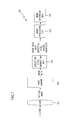
- Fig. 1 is a block diagram showing the structure of an embodiment of a digital camera.
- This digital camera 100 includes a lens 101, an image sensor 102, a defective pixel correction unit 103, an image processing unit 104, and an image recording unit 105.
- the lens 101 consists of a plurality of optical lenses, and images an image of the photographic subject upon the image sensor 102.
- the image sensor 102 is, for example, a CCD or CMOS sensor. This image sensor 102 is exposed for a fixed time period, and thereby the optical image is obtained as image data.
- the image sensor 102 outputs the acquired image data to a defective pixel correction unit 103. At this time, if the image sensor 102 has a clump pixel defect, defective pixels will be present in the image data that has been acquired by the image sensor 102.
- the defective pixel correction unit 103 performs processing that will be described hereinafter, and corrects the defective pixels in the image data captured by this image sensor 102 that has this type of clump pixel defect.
- the defective pixel correction unit 103 outputs the image data after correction to an image processing unit 104.
- the image data that is input from the image sensor 102 is image data in a Bayer array.
- the defective pixels in this image data are of arbitrary shapes within a size of 4x4 pixels.
- the position of each pixel in the image data is specified by coordinate values in a coordinate system that is established with respect to the image data. In this coordinate system, the horizontal direction of the image data will be taken as the X axis and its vertical direction as the Y axis, and the upper left corner of the image data will be taken as the origin.
- the image processing unit 104 After having performed per se known image processing upon the data that has been input such as white balance processing, color interpolation processing, edge enhancement processing, side enhancement processing, and the like, the image processing unit 104 outputs the image data after this image processing to an image recording unit 105.
- this image recording unit 105 records the image data upon an external storage medium such as a memory card or the like, or upon an internal storage medium such as a flash memory or the like.
- the defective pixel correction unit 103, the image processing unit 104, and the image recording unit 105 are constituted by a CPU and peripheral circuitry thereof.
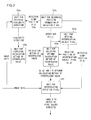
- Fig. 2 is a block diagram showing the structure of the defective pixel correction unit 103.
- the defective pixel correction unit 103 includes an unit 103a for deciding similarity direction, an unit 103b for supplying calculation method of interpolated value, an unit 103c for recording position information of defective pixel, an unit 103d for selecting optimum calculation method of interpolated value, an unit 103e for setting interpolation subject pixel, and an unit 103f for interpolating defective pixel.
- the unit 103c for recording position information of defective pixel is a memory, for example a flash memory, for recording information (hereinafter termed the "defective pixel position information") for specifying the positions and distribution of defective pixels in the image data, as will be described hereinafter.
- the unit 103a for deciding similarity direction, the unit 103d for selecting optimum calculation method of interpolated value, the unit 103e for setting interpolation subject pixel, and the unit 103f for interpolating defective pixel are constituted by a calculation processing unit.
- a defective clump position (P,Q) and a defect map D(i,j) are recorded in the unit 103c for recording position information of defective pixel.
- the defective clump position (P,Q) is the coordinate values of the upper left corner of a 4x4 pixel defective clump region within the image.
- the normal pixels and the defective pixels are distinguished by the respective code values 0 and 1.
- normal pixel includes a pixel that previously manifested an anomaly such as output decrease or the like, but of which output has been corrected to a normal output value by performing previous correction processing such as gain correction or the like, not shown in the figures.
- previous correction processing such as gain correction or the like
- the image data that is output from the image sensor 102 is input to the unit 103a for deciding similarity direction.
- the unit 103a for deciding similarity direction reads in the above described defective clump position (P,Q) from the unit 103c for recording position information of defective pixel. Then the unit 103a for deciding similarity direction calculates the CV, the CH, the C45, and the C135 for the region of which distance is within four pixels from the defective clump region (in other words, for the 12x12 region that is centered upon the 4x4 defect region, excluding the 4x4 region in its center).
- the CV, CH, C45, and C135 are the sums of the absolute values of the differences in value between adjacent pixels of the same color (i. e.
- CV is the sum of the absolute values of the differences in value for adjacent pixels in the vertical direction (i.e., the sum of the absolute values of the differences)
- CH is the sum of the absolute values of the differences in value for adjacent pixels in the horizontal direction
- C45 is the sum of the absolute values of the differences in value for adj acent pixels in the direction that slopes at 45°
- C135 is the sum of the absolute values of the differences in value for adj acent pixels in the direction that slopes at 135°.
- the unit 103a for deciding similarity direction decides that the direction in which the differential absolute value sum is the smallest among these four directions is the similarity direction.
- the unit 103b for supplying calculation method of interpolated value outputs a plurality of calculation methods of interpolated value to the unit 103d for selecting optimum calculation method of interpolated value.
- Calculation methods of interpolated value are set in advance and recorded in the memory for each of the possible similarity directions, i.e. horizontally, vertically, sloping at 45°, and sloping at 135°.
- the unit 103b for supplying calculation method of interpolated value selects, from among these, the calculation methods of interpolated value for the direction that corresponds to the result of the decision by the unit 103a for deciding similarity direction.
- the unit 103b for supplying calculation method of interpolated value outputs these calculation methods of interpolated value that have been selected to the unit 103d for selecting optimum calculation method of interpolated value.
- the unit 103b for supplying calculation method of interpolated value outputs the following eight calculation methods of interpolated value (calculation equations for interpolated value), from a calculation method #1 of interpolated value to a calculation method #8 of interpolated value, to the unit 103d for selecting calculation method of interpolated value:
- the first term in the interpolation equation given as Equation (2) calculates an interpolated value that is to become a reference by obtaining the average of the pixel values for pixels of the same color on the left and right of (x,y). And the second term extracts the minute unevenness structure using the pixels of different colors on the left and right of (x, y) . And, in the interpolation equation of Equation (2), the ability of reproduction of the fine structure is enhanced by adding the minute unevenness structure that has been extracted to the interpolated value that is the reference.
- Equation (3) the interpolation accuracy is somewhat inferior as compared to the calculation method #1 of interpolated value, since the second term that extracts the unevenness structure is imperfect.
- Equation (4) the interpolation accuracy is inferior as compared to the calculation methods #1 and #2 of interpolated value, since only the pixel on the left side of (x,y) are referred to in the calculation of the interpolation value that becomes the reference.
- these calculation methods of interpolated value are ranked in the descending order of their interpolation accuracy.
- each of these calculation methods of interpolated value uses a different combination of the plurality of pixel values that are referred to, they also provide different accuracies of interpolation.
- the unit 103e for setting interpolation subject pixel specifies (1,1), (1,2), (2,1) (2,2), and (3,2) as being the relative positions of the interpolation subject pixel.
- the unit 103e for setting interpolation subject pixel outputs the defect map D(i,j) and the relative positions (p,q) of the interpolation subject pixels to the unit 103d for selecting optimum calculation method of interpolated value.
- the unit 103d for selecting optimum calculation method of interpolated value acquires the calculation methods #1 through #8 of interpolated value that have been input from the unit 103b for supplying calculation method of interpolated value, and the defect map D(i,j) and the relative positions (p, q) of the interpolation subject pixels that have been input from the unit 103e for setting interpolation subject pixel. And while referring to the defect map D(i,j), the unit 103d for selecting optimum calculation method of interpolated value makes decisions as to whether it is possible to apply any of the calculation methods #1 through #8 of interpolated value to the relative positions (p,q) of the interpolation subject pixels. At this time, the unit 103d for selecting optimum calculation method of interpolated value performs these decisions in order from the calculation method #1 of interpolated value.
- the unit 103d for selecting optimum calculation method of interpolated value decides that it is possible to apply this calculation method of interpolated value.
- the unit 103d for selecting optimum calculation method of interpolated value sets the values to 0 when i and j are negative or greater than or equal to 4 in the defect map D(i,j).
- the calculation methods of interpolated value are arranged from #1 in order of decreasing interpolation accuracy, so that the unit 103d for selecting optimum calculation method of interpolated value selects the optimum calculation method of interpolated value by deciding for each calculation method of interpolated value, in order from the calculation method #1 of interpolated value downwards, whether or not it can be applied.
- the unit 103d for selecting optimum calculation method of interpolated value selects the optimum calculation method of interpolated value by deciding for each calculation method of interpolated value, in order from the calculation method #1 of interpolated value downwards, whether or not it can be applied.
- the width of the defective pixel clump is less than or equal to 4 pixels, since at least one of the calculation methods #7 and #8 interpolated value will be determined to be applicable, it is certain that one of the calculation methods interpolated value will be selected by the unit 103d for selecting optimum calculation method of interpolated value.
- the unit 103d for selecting optimum calculation method of interpolated value outputs the relative positions (p,q) of the interpolation subject pixels, and the optimum calculation methods of interpolated value for interpolating at these relative positions (p,q) of the interpolation subject pixels, to the unit 103f for interpolating defective pixel.
- the unit 103f for interpolating defective pixel acquires the relative positions (p,q) of the interpolation subject pixels that are input from the unit 103d for selecting optimum calculation method of interpolated value and the corresponding optimum calculation methods of interpolated value for performing interpolation at these positions. And the unit 103f for interpolating defective pixel reads in the above described defective clump positions (P,Q) from the unit 103c for recording position information of defective pixel.
- the unit 103f for interpolating defective pixel is able to generate an interpolated defective pixel A (P+p, Q+q) in the image data, by using the optimum interpolated values that have been calculated by using the optimum calculation method of interpolated value selected by the unit 103d for selecting optimum calculation method of interpolated value.
- the unit 103d for selecting optimum calculation method of interpolated value interpolates the relative position (p,q) of interpolation subject pixels using those pixels that are of the same color as the relative position (p,q) of interpolation subj ect pixels among the pixels around this relative position (p,q) of interpolation subject pixels. Thereafter, the unit 103d for selecting optimum calculation method of interpolated value interpolates the relative position (p, q) of interpolation subject pixels using those pixels that are of a different color from the relative position (p,q) of interpolation subj ect pixels among the pixels around this relative position (p, q) of interpolation subject pixels.
- the unit 103b for supplying calculation method of interpolated value outputs calculation methods of interpolated value that may be used for this to the unit 103d for selecting optimum calculation method of interpolated value.
- the unit 103b for supplying calculation method of interpolated value outputs a plurality of calculation methods of interpolated value to the unit 103d for selecting optimum calculation method of interpolated value according to the similarity direction decided upon by the unit 103a for deciding similarity direction. For example, if the decision result for the similarity direction made by the unit 103a for deciding similarity direction is the horizontal direction, the unit 103b for supplying calculation method of interpolated value outputs the following reference calculation methods #1 through #3 of interpolated value, and the following auxiliary calculation methods of interpolated value that correspond to these reference calculation methods of interpolated value to the unit 103d for optimum calculation method of interpolated value.
- the unit 103d for selecting optimum calculation method of interpolated value acquires the reference calculation methods #1 through #3 of interpolated value that have been input from the unit 103b for supplying calculation method of interpolated value, and the respectively corresponding auxiliary calculation methods of interpolated value that respectively correspond to these reference calculation methods of interpolated value. And the unit 103d for selecting optimum calculation method of interpolated value acquires the defect map D(i,j) and the relative positions (p,q) of the interpolation subject pixels that have been input from the unit 103e for setting interpolation subject pixel.
- the unit 103d for selecting optimum calculation method of interpolated value makes decisions as to whether it is possible to apply any of the reference calculation methods from #1 of interpolated value in order to the relative positions (p,q) of the interpolation subject pixels, and selects the first such reference method for which the result of making the decision described above is applicable, as the optimum reference calculation method of interpolated value.
- the unit 103d for selecting optimum calculation method of interpolation value makes decisions as to whether it is possible to apply any of the auxiliary calculation methods of interpolated value that correspond to this optimum reference calculation method of interpolated value, from #1 onwards in order, and selects the first such auxiliary method for which the result of making the decision described above is applicable, as the optimum auxiliary calculation method of interpolated value.
- the unit 103d for selecting optimum calculation method of interpolated value outputs, to the unit 103f for interpolating defective pixel, the relative positions (p,q) of interpolation subject pixels, and the optimum reference calculation method of interpolated value and the optimum auxiliary calculation method of interpolated value for interpolating the relative positions (p,q) of interpolation subject pixels.
- the unit 103f for interpolating defective pixel acquires the relative positions (p, q) of interpolation subject pixels input from the unit 103d for selecting optimum calculation method of interpolated value, and the optimum reference calculation method of interpolated value and the optimum auxiliary calculation method of interpolated value for interpolating it. And the unit 103f for interpolating defective pixel reads in the defective clump position (P,Q) described above from the unit 103c for recording position information of defective pixel.
- the following advantageous effect may be obtained. That is, it is arranged to perform the calculation by dividing the optimum calculation method of interpolated value into the optimum reference calculation method of interpolated value and the optimum auxiliary calculation method of interpolated value, and to generate the interpolated defective pixel A(P+p,Q+q) using these.
- it is possible to obtain the advantageous effects of being able to economize upon the amount of memory for recording the calculation methods of interpolated value and to economize upon the amount of calculation for optimum interpolated value selection.
- the second embodiment it is possible to add a correction to the auxiliary interpolated value, since the calculation distinguishes between the auxiliary interpolated value and the reference interpolated value. For example, it would be acceptable to arrange to perform clipping processing so that the auxiliary interpolated value does not become too large. In concrete terms, it would be acceptable to impose a limit, so that the absolute value of the auxiliary interpolated value stays within around one eighth of the general level of the pixel values. The following advantageous effects may be obtained by this type of processing.
- the color component of the auxiliary interpolated value is large with respect to the magnitude of the color component of the reference interpolated value at the spot where defect correction is performed, sometimes it happens that the magnitude of a high frequency component that is calculated as the auxiliary interpolated value becomes greater than the actual high frequency component of the color component of the reference interpolated value, so that some inappropriate structure is added. Accordingly, if the auxiliary interpolated value becomes a large value, it is not desirable to add this just as it without any change to the reference interpolated value, but rather it is desirable to limit the magnitude of the auxiliary interpolated value that is added on, as in the processing described above.
Landscapes
- Engineering & Computer Science (AREA)
- Multimedia (AREA)
- Signal Processing (AREA)
- Transforming Light Signals Into Electric Signals (AREA)
- Color Television Image Signal Generators (AREA)
- Studio Devices (AREA)
Abstract
Description
- The disclosures of the following priority applications are herein incorporated by reference:
- Japanese Patent Application No.
2007-339351 filed December 28, 2007 - Japanese Patent Application No.
2008-313480 filed December 9, 2008 - The present invention relates to an image processing apparatus and to an imaging apparatus.
- In Japanese Laid-Open Patent Publication
2005-223815 3,951,992 - Generally, a color component that is missing from a Bayer image is calculated as follows. That is, first, the average value is calculated using the pixel values of the same color as a subject color component among the pixels around a subject location. And the unevenness structure at the subject location is extracted using pixel values of a different color or the like as the subject color component, and this extracted value is added to the average value. Due to this, the accuracy is enhanced by recreating the fine structure and by suppressing false color. However, with a prior art image processing apparatus, when correcting a defective clump of an arbitrary shape, the uneven-nesses of the other color components are not added to the interpolated values. Accordingly, the accuracy with which the fine structure is recreated and the false color is suppressed is not sufficient.
- According to the 1st aspect of the present invention, an image processing apparatus comprises: a storage means for recordingposition information for a defective pixel; a setting means for setting the defective pixel as an interpolation subject pixel, on the basis of the recorded position information; a selection means for selecting an optimum calculation equation for interpolated value from among a plurality of calculation equations for interpolated value in order to interpolate the pixel value of the interpolation subject pixel; and an interpolation means for interpolating the pixel value of the interpolation subject pixel by using the optimum calculation equation for interpolated value selected by the selection means; wherein the optimum calculation equation for interpolated value is one of the calculation equations for interpolated value that can be applied to the interpolation subj ect pixel, and has the highest interpolation accuracy of the calculation equations for interpolated value.
- According to the 2nd aspect of the present invention, in the image processing apparatus according to the 1st aspect, it is preferred that the calculation equations for interpolated value use pixel values of a plurality of reference pixels for interpolation that are arranged around the interpolation subject pixel; and each of the plurality of calculation equations for interpolated value has a mutually different combination of pixel values of the plurality of reference pixels for interpolation that are used, and has mutually different interpolation accuracies; and the selection means: decides that each one of the calculation equations for interpolated value can be applied to the interpolation subject pixel, if the plurality of reference pixels for interpolation used by the calculation equation for interpolated value do not include any defective pixel except for the interpolation subject pixel; and selects the calculation equation for interpolated value of which interpolation accuracy is the highest among the calculation equations for interpolated value decided as being applicable, as the optimum calculation equation for interpolated value.
- According to the 3rd aspect of the present invention, in the image processing apparatus according to the 1st aspect, it is preferred that the calculation equation for interpolated value includes a reference calculation equation for interpolated value and an auxiliary calculation equation for interpolated value;theselection means,after havingselected an optimum reference calculation equation for interpolated value from among a plurality of the reference calculation equations for interpolated value, selects an optimum auxiliary calculation equation for interpolated value from among a plurality of the auxiliary calculation equations for interpolated value corresponding to the optimum reference calculation equation for interpolated value that has been selected; the interpolation means performs interpolation so that a value obtained by adding together a reference interpolated value and an auxiliary interpolated value becomes the pixel value for the interpolation subject pixel, the reference interpolated value being calculated by using the optimum reference calculation equation for interpolated value and the auxiliary interpolated value being calculated by using the optimum auxiliary calculation equation for interpolated value; the optimum reference calculation equation for interpolated value is one of the reference calculation equations for interpolated value that can be applied to the interpolation subj ect pixel, and has the highest interpolation accuracy of the reference calculation equations for interpolated value; and the optimum auxiliary calculation equation for interpolated value is one of the auxiliary calculation equations for interpolated value that can be applied to the interpolation subject pixel, and has the highest interpolation accuracy of the auxiliary calculation equations for interpolated value.
- According to the 4th aspect of the present invention, in the image processing apparatus according to the 2nd or 3rd aspects, it is preferred that the selection means: calculates a position of the reference pixel for interpolation in an image data, on the basis of a position of the interpolation subject pixel in the image data and a relative position information of the reference pixel for interpolation with respect to the interpolation subject pixel; decides whether or not the reference pixel for interpolation is a defective pixel, on the basis of the position of the reference pixel for interpolation in the image data and a position information of the defective pixel; and decides that the calculation equation for interpolated value can be applied to the interpolation subject pixel, if the reference pixel for interpolation is decided as not being a defective pixel.
- According to the 5th aspect of the present invention, in the image processing apparatus according to the 1st aspect, it is preferred that the selection means: decides whether or not each of the calculation equations for interpolated value can be applied to the interpolation subject pixel, in descending order of interpolation accuracy; and selects the calculation equation for interpolated value that is first decided as being applicable, as the optimum calculation equation for interpolated value.
- According to the 6th aspect of the present invention, in the image processing apparatus according to the 3rd aspect, it is preferred that the selection means: decides whether or not each of the reference calculation equations for interpolated value can be applied to the interpolation subject pixel, in descending order of interpolation accuracy; and selects the reference calculation equation for interpolated value that is first decided as being applicable, as the optimum reference calculation equation for interpolated value.
- According to the 7th aspect of the present invention, in the image processing apparatus according to the 3rd or 6th aspects, it is preferred that the selection means: decides whether or not each of the auxiliary calculation equations for interpolated value can be applied to the interpolation subject pixel, in descending order of interpolation accuracy; and selects the auxiliary calculation equation for interpolated value that is first decided as being applicable, as the optimum auxiliary calculation equation for interpolated value.
- According to the 8th aspect of the present invention, it is preferred that the image processing apparatus according to any one of the 1st through 7th aspects further comprises: a similarity direction decision means for deciding upon a similarity direction of an image structure in a neighborhood of the interpolation subject pixel; and wherein: the selection means selects the optimum calculation equations for interpolated value from among the plurality of calculation equations for interpolated value, according to the similarity direction that has been decided upon by the similarity direction decision means.
- According to the 9th aspect of the present invention, An image processing apparatus comprises: a storage means for recording a position information of a plurality of defective pixels; and an interpolation means for: selecting a first calculation equation for interpolated value that can be applied to the defective pixel from among a plurality of calculation equations for interpolated value in order to interpolate a pixel value of the defective pixel, by using normal pixels that have a same color as the defective pixel does among the pixels in a neighborhood of the defective pixels of the same color as that of the defective pixel; selecting a second calculation equation for interpolated value that can be applied to the defective pixel from among a plurality of calculation equations for interpolated value in order to interpolate the pixel value of the defective pixel, by using normal pixels that have different colors from the defective pixel does among the pixels in the neighborhood of the defective pixel; and interpolating the pixel value of the defective pixel, using the position information for the defective pixel, the first calculation equation for interpolated value, and the second calculation equation for interpolated value.
- According to the 10th aspect of the present invention, in the image processing apparatus according to the 9th aspect, it is preferred that the interpolation means: if there are a plurality of calculation equations for interpolated value that can be applied to the defective pixel among the plurality of calculation equations for interpolated value in order to interpolate the pixel value of the defective pixel by using normal pixels that have the same color as the defective pixel does, selects the calculation equation for interpolated value of which interpolation accuracy is the highest of the calculation equations for interpolated value that can be applied to the defective pixel, as the first calculation equation for interpolated value; and if there are a plurality of calculation equations for interpolated value that can be applied to the defective pixel among the plurality of calculation equations for interpolated value in order to interpolate the pixel value of the defective pixel by using normal pixels that have different colors from the defective pixel does, the calculation equation for interpolated value of which interpolation accuracy is the highest of the calculation equations for interpolated value that can be applied to the defective pixel, as the second calculation equation for interpolated value.
- According to the 11th aspect of the present invention, in the image processing apparatus according to the 9th or the 10th aspects, it is preferred that the interpolation means decides upon a similarity direction of an image structure in the neighborhood of the defective pixel, and selects the first calculation equation for interpolated value and the second calculation equation for interpolated value from among the plurality of calculation equations for interpolated value, according to the decided similarity direction.
- According to the 12th aspect of the present invention, an imaging apparatus comprises: an image sensor that captures an image of a photographic subject; and an image processing apparatus according to any one of the 1st through 11th aspects, that creates image data by performing image processing upon an image signal output from the image sensor; wherein: the image processing apparatus creates the image data by interpolating the pixel value of a defective pixel included in the image sensor by using the image signal that is output from the image sensor.
-
-
Fig. 1 is a block diagram showing the structure of an embodiment of a digital camera; -
Fig. 2 is a block diagram showing the structure of a defectivepixel correction unit 103; and -
Fig. 3 is a figure showing a concrete example of a defect map D(i,j). -
Fig. 1 is a block diagram showing the structure of an embodiment of a digital camera. Thisdigital camera 100 includes alens 101, animage sensor 102, a defectivepixel correction unit 103, animage processing unit 104, and animage recording unit 105. - The
lens 101 consists of a plurality of optical lenses, and images an image of the photographic subject upon theimage sensor 102. Theimage sensor 102 is, for example, a CCD or CMOS sensor. Thisimage sensor 102 is exposed for a fixed time period, and thereby the optical image is obtained as image data. Theimage sensor 102 outputs the acquired image data to a defectivepixel correction unit 103. At this time, if theimage sensor 102 has a clump pixel defect, defective pixels will be present in the image data that has been acquired by theimage sensor 102. The defectivepixel correction unit 103 performs processing that will be described hereinafter, and corrects the defective pixels in the image data captured by thisimage sensor 102 that has this type of clump pixel defect. The defectivepixel correction unit 103 outputs the image data after correction to animage processing unit 104. - It should be understood that, in this embodiment, the image data that is input from the
image sensor 102 is image data in a Bayer array. Moreover, it will be supposed that the defective pixels in this image data are of arbitrary shapes within a size of 4x4 pixels. In this embodiment, it will be supposed that the position of each pixel in the image data is specified by coordinate values in a coordinate system that is established with respect to the image data. In this coordinate system, the horizontal direction of the image data will be taken as the X axis and its vertical direction as the Y axis, and the upper left corner of the image data will be taken as the origin. - After having performed per se known image processing upon the data that has been input such as white balance processing, color interpolation processing, edge enhancement processing, side enhancement processing, and the like, the
image processing unit 104 outputs the image data after this image processing to animage recording unit 105. For example, thisimage recording unit 105 records the image data upon an external storage medium such as a memory card or the like, or upon an internal storage medium such as a flash memory or the like. It should be understood that the defectivepixel correction unit 103, theimage processing unit 104, and theimage recording unit 105 are constituted by a CPU and peripheral circuitry thereof. -
Fig. 2 is a block diagram showing the structure of the defectivepixel correction unit 103. In the following, the processing that is executed by this defectivepixel correction unit 103 will be explained using thisFig. 2 . The defectivepixel correction unit 103 includes anunit 103a for deciding similarity direction, anunit 103b for supplying calculation method of interpolated value, anunit 103c for recording position information of defective pixel, anunit 103d for selecting optimum calculation method of interpolated value, anunit 103e for setting interpolation subject pixel, and anunit 103f for interpolating defective pixel. It should be understood that theunit 103c for recording position information of defective pixel is a memory, for example a flash memory, for recording information (hereinafter termed the "defective pixel position information") for specifying the positions and distribution of defective pixels in the image data, as will be described hereinafter. It should be understood that theunit 103a for deciding similarity direction, theunit 103d for selecting optimum calculation method of interpolated value, theunit 103e for setting interpolation subject pixel, and theunit 103f for interpolating defective pixel are constituted by a calculation processing unit. - As defective pixel position information, a defective clump position (P,Q) and a defect map D(i,j) (where i=0∼3, j=0∼3) are recorded in the
unit 103c for recording position information of defective pixel. The defective clump position (P,Q) is the coordinate values of the upper left corner of a 4x4 pixel defective clump region within the image. And the defect map D(i,j) (where i=0∼3, j=0∼3) is map information for specifying whether or not each of the pixels in this defective clump region is defective. It should be understood that the defective clump position (P,Q) and the defect map (D(i,j) (where i=0∼3, j=0∼3) are generated on the basis of the results of investigating the defective pixel characteristics of the image sensor, before shipment of this digital camera. - As shown in
Fig. 3 , in this defect map D(i,j), the normal pixels and the defective pixels are distinguished by therespective code values - First, the image data that is output from the
image sensor 102 is input to theunit 103a for deciding similarity direction. Theunit 103a for deciding similarity direction reads in the above described defective clump position (P,Q) from theunit 103c for recording position information of defective pixel. Then theunit 103a for deciding similarity direction calculates the CV, the CH, the C45, and the C135 for the region of which distance is within four pixels from the defective clump region (in other words, for the 12x12 region that is centered upon the 4x4 defect region, excluding the 4x4 region in its center). The CV, CH, C45, and C135 are the sums of the absolute values of the differences in value between adjacent pixels of the same color (i. e. the sums of the absolute values of the adjacent pixel differences). Here, CV is the sum of the absolute values of the differences in value for adjacent pixels in the vertical direction (i.e., the sum of the absolute values of the differences), while CH is the sum of the absolute values of the differences in value for adjacent pixels in the horizontal direction. Moreover, C45 is the sum of the absolute values of the differences in value for adj acent pixels in the direction that slopes at 45°, while C135 is the sum of the absolute values of the differences in value for adj acent pixels in the direction that slopes at 135°. And theunit 103a for deciding similarity direction decides that the direction in which the differential absolute value sum is the smallest among these four directions is the similarity direction. - According to the similarity direction that has been decided upon by the
unit 103a for deciding similarity direction, theunit 103b for supplying calculation method of interpolated value outputs a plurality of calculation methods of interpolated value to theunit 103d for selecting optimum calculation method of interpolated value. Calculation methods of interpolated value are set in advance and recorded in the memory for each of the possible similarity directions, i.e. horizontally, vertically, sloping at 45°, and sloping at 135°. Theunit 103b for supplying calculation method of interpolated value selects, from among these, the calculation methods of interpolated value for the direction that corresponds to the result of the decision by theunit 103a for deciding similarity direction. And theunit 103b for supplying calculation method of interpolated value outputs these calculation methods of interpolated value that have been selected to theunit 103d for selecting optimum calculation method of interpolated value. - By way of example, it will be supposed that the decision result regarding similarity direction by the
unit 103a for deciding similarity direction has been the horizontal direction. At this time, as the plurality of calculation methods of interpolated value referring to pixels in the horizontal direction, theunit 103b for supplying calculation method of interpolated value outputs the following eight calculation methods of interpolated value (calculation equations for interpolated value), from acalculation method # 1 of interpolated value to a calculation method #8 of interpolated value, to theunit 103d for selecting calculation method of interpolated value: -
Calculation method # 1 of interpolatedvalue: n=6, X={-2, 2, -3, -1, 1, 3}, Y={0, 0, 0, 0, 0, 0}, K={2, 2, -1, 1, 1, -1}. - Calculation method #2 of interpolated value: n=4, X={-2, 2, -3, -1}, Y={0, 0, 0, 0}, K={2, 2, -1, 1}.
- Calculation method #3 of interpolatedvalue: n=4, X={-2, 2, 1, 3}, Y={0, 0, 0, 0}, K={2, 2, 1, -1}.
- Calculation method #4 of interpolated value: n=2, X={-2, 2}, Y={0, 0}, K={2, 2}.
- Calculation method #5 of interpolated value: n=3, X={-2, -3, -1}, Y={0, 0, 0}, K={4, -2, 2}.
- Calculation method #6 of interpolated value: n=3, X={2, 1, 3}, Y={0, 0, 0}, K={4, 2, -2}.
- Calculation method #7 of interpolated value: n=1, X={-2}, Y={0}, K={4}.
- Calculation method #8 of interpolated value : n=1, X={2}, Y={0}, K={4}.
- It should be understood that, in the above described
calculation method # 1 of interpolated value, the term "X={-2, 2, -3, -1, 1, 3}" means that the values in an array X are as follows: - X[0] = -2
- X[1] - 2
- X[2] = -3
- X[3] = -1
- X[4] = 1
- X[5] = 3
- The above described integer n and arrays X, Y, and K are parameters that specify the interpolation method; and the processing for calculating the pixel value A(x,y) at the coordinates (x,y) is performed according to the following Equation (1):
Equation #1:
- For example, the interpolation equation for the
calculation method # 1 of interpolated value becomes the following Equation (2):
Equation #2:
- Here, the first term in the interpolation equation given as Equation (2) calculates an interpolated value that is to become a reference by obtaining the average of the pixel values for pixels of the same color on the left and right of (x,y). And the second term extracts the minute unevenness structure using the pixels of different colors on the left and right of (x, y) . And, in the interpolation equation of Equation (2), the ability of reproduction of the fine structure is enhanced by adding the minute unevenness structure that has been extracted to the interpolated value that is the reference.
- And the interpolation equation for the calculation method #2 of interpolated value becomes the following Equation (3) :
Equation #3:
- With this interpolation equation shown in Equation (3), the interpolation accuracy is somewhat inferior as compared to the
calculation method # 1 of interpolated value, since the second term that extracts the unevenness structure is imperfect. - Moreover, the interpolation equation for the calculation method #5 of interpolated value becomes the following Equation (4):
Equation #4:
- With this interpolation equation shown in Equation (4), the interpolation accuracy is inferior as compared to the
calculation methods # 1 and #2 of interpolated value, since only the pixel on the left side of (x,y) are referred to in the calculation of the interpolation value that becomes the reference. Thus, these calculation methods of interpolated value are ranked in the descending order of their interpolation accuracy. In other words, while each of these calculation methods of interpolated value uses a different combination of the plurality of pixel values that are referred to, they also provide different accuracies of interpolation. - The
unit 103e of setting interpolation subject pixel reads in the defect map D(i,j) (where i=0∼3 and j=0∼3) from theunit 103c for recording position information of defective pixel, and specifies the pixel positions (p,q) (i.e. the relative positions of the interpolation subject pixels) of the pixels that satisfy D(p,q)=1 in the defect map D(i,j). For example, in the shown inFig. 3 , theunit 103e for setting interpolation subject pixel specifies (1,1), (1,2), (2,1) (2,2), and (3,2) as being the relative positions of the interpolation subject pixel. And theunit 103e for setting interpolation subject pixel outputs the defect map D(i,j) and the relative positions (p,q) of the interpolation subject pixels to theunit 103d for selecting optimum calculation method of interpolated value. - The
unit 103d for selecting optimum calculation method of interpolated value acquires thecalculation methods # 1 through #8 of interpolated value that have been input from theunit 103b for supplying calculation method of interpolated value, and the defect map D(i,j) and the relative positions (p, q) of the interpolation subject pixels that have been input from theunit 103e for setting interpolation subject pixel. And while referring to the defect map D(i,j), theunit 103d for selecting optimum calculation method of interpolated value makes decisions as to whether it is possible to apply any of thecalculation methods # 1 through #8 of interpolated value to the relative positions (p,q) of the interpolation subject pixels. At this time, theunit 103d for selecting optimum calculation method of interpolated value performs these decisions in order from thecalculation method # 1 of interpolated value. - If the pixels referred to by the calculation method of interpolated value are all normal, the
unit 103d for selecting optimum calculation method of interpolated value decides that it is possible to apply this calculation method of interpolated value. In concrete terms, theunit 103d for selecting optimum calculation method of interpolated value sets the values to 0 when i and j are negative or greater than or equal to 4 in the defect map D(i,j). At this time, if the following Equation (5) is valid, theunit 103d for selecting optimum calculation method of interpolated value decides that this calculation method of interpolated value can be applied:
Equation #5:
- The
unit 103d for selecting optimum calculation method of interpolated value selects the first calculation method of interpolated value for which the result of making the decision described above is applicable, as the optimum calculation method of interpolated value. For example, with the defect map D(i,j) shown inFig. 3 : for (p,q)=(1,1), the calculation method #2 of interpolated value is selected as the optimum calculation method of interpolated value; while, for (p,q)=(1,2), the calculation method #3 of interpolated value is selected as the optimum calculation method of interpolated value. Moreover, for (p,q)=(2,1), the calculation method #5 of interpolated value is selected as the optimum calculation method of interpolated value; for (p,q)=(2,2), the calculation method #4 of interpolated value is selected as the optimum calculation method of interpolated value; and for (p,q)=(3,2), the calculation method #6 of interpolated value is selected as the optimum calculation method of interpolated value. - As described above, the calculation methods of interpolated value are arranged from #1 in order of decreasing interpolation accuracy, so that the
unit 103d for selecting optimum calculation method of interpolated value selects the optimum calculation method of interpolated value by deciding for each calculation method of interpolated value, in order from thecalculation method # 1 of interpolated value downwards, whether or not it can be applied. As a result, it is possible to select the calculation method of interpolated value for which the interpolation accuracy is the highest among the calculation methods of interpolated value that actually can be applied, as the optimum calculation method of interpolated value. It should be understood that, if the width of the defective pixel clump is less than or equal to 4 pixels, since at least one of the calculation methods #7 and #8 interpolated value will be determined to be applicable, it is certain that one of the calculation methods interpolated value will be selected by theunit 103d for selecting optimum calculation method of interpolated value. - The
unit 103d for selecting optimum calculation method of interpolated value outputs the relative positions (p,q) of the interpolation subject pixels, and the optimum calculation methods of interpolated value for interpolating at these relative positions (p,q) of the interpolation subject pixels, to theunit 103f for interpolating defective pixel. - The
unit 103f for interpolating defective pixel acquires the relative positions (p,q) of the interpolation subject pixels that are input from theunit 103d for selecting optimum calculation method of interpolated value and the corresponding optimum calculation methods of interpolated value for performing interpolation at these positions. And theunit 103f for interpolating defective pixel reads in the above described defective clump positions (P,Q) from theunit 103c for recording position information of defective pixel. Then theunit 103f for interpolating defective pixel generates an interpolated defective pixel A (P+p,Q+q) at each of the relative positions (p, q) of the interpolation subject pixels, by using the parameters n, X, Y, and K of the optimum calculation method of interpolated value, according to the following Equation (6) :
Equation #6:
- By doing this, the
unit 103f for interpolating defective pixel is able to generate an interpolated defective pixel A (P+p, Q+q) in the image data, by using the optimum interpolated values that have been calculated by using the optimum calculation method of interpolated value selected by theunit 103d for selecting optimum calculation method of interpolated value. - According to the first embodiment as explained above, the following beneficial operational effects may be obtained.
- (1) It is arranged to record the position information of defective pixel for the image sensor in the
unit 103c for recording position information of defective pixel. It is arranged for theunit 103b for supplying calculation method of interpolated value to supply a plurality of calculation methods of interpolated value for generating the interpolated pixel values at the defective pixels to theunit 103d for selecting optimum calculation method of interpolated value, and for theunit 103e for setting interpolation subject pixel to set the defective pixels as the interpolation subject pixels. Moreover, it is arranged for theunit 103d for selecting optimum calculation method of interpolated value to select, as the optimum calculation method of interpolated value, , a calculation method of interpolated value that can be applied to the interpolation subject pixel that has been set by theunit 103e for setting interpolation subject pixel and has the highest interpolation accuracy among the calculation methods of interpolated value that have been supplied from theunit 103b for supplying calculated method of interpolated value. Furthermore, it is arranged for theunit 103f for interpolating defective pixel to generate an interpolated pixel value at the interpolation subject pixel by using that optimum calculation method of interpolated value that has been selected by theunit 103d for selecting optimum calculation method of interpolated value. Due to this, in the interpolation of the defective pixel image data, it is possible to improve the accuracy at which the fine structure is reproduced, while also being able to enhance the accuracy of false color suppression. - (2) For each of the calculation methods of interpolated value, the
unit 103b for supplying calculation method of interpolated value supplies relative position information for the reference pixels for interpolation with respect to the interpolation subject pixels to theunit 103d for selecting optimum calculation method of interpolated value. Theunit 103d for selecting optimum calculation method of interpolated value obtains the positions of the reference pixels for interpolation within the image data, on the basis of the positions of the interpolation subject pixels within the image data and the relative position information for the reference pixels for interpolation within the image data. Then it is arranged for theunit 103d for selecting optimum calculation method of interpolated value to decide whether or not a reference pixel for interpolation is a defective pixel, on the basis of the position of this reference pixel for interpolation within the image data and the defective pixel position information within the image data; and to decide whether this calculation method of interpolated value can be applied if it has decided that this the reference pixel for interpolation is not a defective pixel. By doing this, it is possible to enhance the accuracy of the interpolation, since it is possible to perform the interpolation by referring only to pixels that are normal. - (3) It is arranged for the
unit 103d for selecting optimum calculation method of interpolated value to decide whether the various proposed calculationmethods of interpolated, value can be applied, in the descending order of their interpolation accuracy, and to select, as the optimum auxiliary calculation method of interpolated value, the first one thereof that it has decided can be applied. Due to this, it is possible to interpolate the defective pixels while using the calculation method of interpolated value that has the highest accuracy. - (4) It is arranged for the
unit 103a for deciding similarity direction to decide upon the similarity direction of the structure of the image in the neighborhood of the interpolation subject pixel, and for theunit 103b for supplying calculation method of interpolated value to supply a plurality of calculation methods of interpolated value, on the basis of the similarity direction that has been decided upon by theunit 103a for deciding similarity direction. Due to this it becomes possible to perform interpolation at high accuracy, by using the pixel values of pixels that are arranged in along the similarity direction with the interpolation subject pixels. - In a second embodiment, the
unit 103d for selecting optimum calculation method of interpolated value interpolates the relative position (p,q) of interpolation subject pixels using those pixels that are of the same color as the relative position (p,q) of interpolation subj ect pixels among the pixels around this relative position (p,q) of interpolation subject pixels. Thereafter, theunit 103d for selecting optimum calculation method of interpolated value interpolates the relative position (p, q) of interpolation subject pixels using those pixels that are of a different color from the relative position (p,q) of interpolation subj ect pixels among the pixels around this relative position (p, q) of interpolation subject pixels. Theunit 103b for supplying calculation method of interpolated value outputs calculation methods of interpolated value that may be used for this to theunit 103d for selecting optimum calculation method of interpolated value. - In this second embodiment, it should be understood that since the figures would be similar to
Figs. 1 through 3 for the first embodiment, explanation thereof will be omitted. Moreover since the processing performed by theunit 103a for deciding similarity direction, theunit 103c for recording position information of defective pixel, and theunit 103e for setting interpolation subject pixel among thevarious units 103a through 103f shown inFig. 2 is similar to that in the first embodiment, explanation thereof will also be omitted. - The
unit 103b for supplying calculation method of interpolated value outputs a plurality of calculation methods of interpolated value to theunit 103d for selecting optimum calculation method of interpolated value according to the similarity direction decided upon by theunit 103a for deciding similarity direction. For example, if the decision result for the similarity direction made by theunit 103a for deciding similarity direction is the horizontal direction, theunit 103b for supplying calculation method of interpolated value outputs the following referencecalculation methods # 1 through #3 of interpolated value, and the following auxiliary calculation methods of interpolated value that correspond to these reference calculation methods of interpolated value to theunit 103d for optimum calculation method of interpolated value. - Reference
calculation method # 1 of interpolated value: n=2, X={-2, 2}, Y={0, 0}, K=2, 2}. - Auxiliary
calculation method # 1 of interpolated value corresponding to the referencecalculation method # 1 of interpolated value: n=4, X={-3, -1, 1, 3}, Y={0, 0, 0, 0}, K={-1, 1, 1, -1}. - Auxiliary calculation method #2 of interpolated value corresponding to the reference
calculation method # 1 of interpolated value: n=2, X={-3, -1}, Y={0, 0}, K={-1, 1}. - Auxiliary calculation method #3 of interpolated value corresponding to the reference
calculation method # 1 of interpolated value: n=2, X={1, 3), Y={0, 0}, K={1, -1}. - Auxiliary calculation method #4 of interpolated value corresponding to the reference
calculation method # 1 of interpolated value: n=0, X={ }, y={ }, K={ }. - Reference calculation method #2 of interpolated value: n=1, X={-2}, Y={0}, K={2}.
- Auxiliary
calculation method # 1 of interpolated value corresponding to the reference calculation method #2 of interpolated value: n=2, X={-3, -1}, Y={0, 0}, K={-1, 1}. - Auxiliary calculation method #2 of interpolated value corresponding to the reference calculation method #2 of interpolated value: n=0, X={ }, Y={}, K={}.
- Reference calculation method #3 of interpolated value: n=1, X={-2}, Y={0}, K={2}.
- Auxiliary
calculation method # 1 of interpolated value corresponding to the reference calculation method #3 of interpolated value: n=2, X={1, 3}, Y={0, 0}, K={1, -1}. - Auxiliary calculation method #2 of interpolated value corresponding to the reference calculation method #3 of interpolated value: n=0, X={ }, Y={}, K={ }.
- The
unit 103d for selecting optimum calculation method of interpolated value acquires the referencecalculation methods # 1 through #3 of interpolated value that have been input from theunit 103b for supplying calculation method of interpolated value, and the respectively corresponding auxiliary calculation methods of interpolated value that respectively correspond to these reference calculation methods of interpolated value. And theunit 103d for selecting optimum calculation method of interpolated value acquires the defect map D(i,j) and the relative positions (p,q) of the interpolation subject pixels that have been input from theunit 103e for setting interpolation subject pixel. - In a similar manner to the first embodiment described above, the
unit 103d for selecting optimum calculation method of interpolated value makes decisions as to whether it is possible to apply any of the reference calculation methods from #1 of interpolated value in order to the relative positions (p,q) of the interpolation subject pixels, and selects the first such reference method for which the result of making the decision described above is applicable, as the optimum reference calculation method of interpolated value. Next, theunit 103d for selecting optimum calculation method of interpolation value makes decisions as to whether it is possible to apply any of the auxiliary calculation methods of interpolated value that correspond to this optimum reference calculation method of interpolated value, from #1 onwards in order, and selects the first such auxiliary method for which the result of making the decision described above is applicable, as the optimum auxiliary calculation method of interpolated value. - And the
unit 103d for selecting optimum calculation method of interpolated value outputs, to theunit 103f for interpolating defective pixel, the relative positions (p,q) of interpolation subject pixels, and the optimum reference calculation method of interpolated value and the optimum auxiliary calculation method of interpolated value for interpolating the relative positions (p,q) of interpolation subject pixels. - The
unit 103f for interpolating defective pixel acquires the relative positions (p, q) of interpolation subject pixels input from theunit 103d for selecting optimum calculation method of interpolated value, and the optimum reference calculation method of interpolated value and the optimum auxiliary calculation method of interpolated value for interpolating it. And theunit 103f for interpolating defective pixel reads in the defective clump position (P,Q) described above from theunit 103c for recording position information of defective pixel. - And, first, using the parameters n, X, Y, and K of the optimum reference calculation method of interpolated value for the relative positions (p,q) of interpolation subject pixels, the
unit 103f for interpolating defective pixel generates a reference interpolated value for the defective pixel A(P+p,Q+q) according to the following Equation (7):
Equation #7:
- Next, using the parameters n, X, Y, and K of the optimum auxiliary calculation method of interpolated value, the
unit 103f for interpolating defective pixel adds an auxiliary interpolated value to the defective pixel A (P+p,Q+q) according to the following Equation (8):
Equation #8:
- According to the second embodiment as explained above, in additional to the beneficial operational effects with the first embodiment, the following advantageous effect may be obtained. That is, it is arranged to perform the calculation by dividing the optimum calculation method of interpolated value into the optimum reference calculation method of interpolated value and the optimum auxiliary calculation method of interpolated value, and to generate the interpolated defective pixel A(P+p,Q+q) using these. As a result, it is possible to obtain the advantageous effects of being able to economize upon the amount of memory for recording the calculation methods of interpolated value and to economize upon the amount of calculation for optimum interpolated value selection.
- Furthermore, according to the second embodiment, it is possible to add a correction to the auxiliary interpolated value, since the calculation distinguishes between the auxiliary interpolated value and the reference interpolated value. For example, it would be acceptable to arrange to perform clipping processing so that the auxiliary interpolated value does not become too large. In concrete terms, it would be acceptable to impose a limit, so that the absolute value of the auxiliary interpolated value stays within around one eighth of the general level of the pixel values. The following advantageous effects may be obtained by this type of processing.
- If the color component of the auxiliary interpolated value is large with respect to the magnitude of the color component of the reference interpolated value at the spot where defect correction is performed, sometimes it happens that the magnitude of a high frequency component that is calculated as the auxiliary interpolated value becomes greater than the actual high frequency component of the color component of the reference interpolated value, so that some inappropriate structure is added. Accordingly, if the auxiliary interpolated value becomes a large value, it is not desirable to add this just as it without any change to the reference interpolated value, but rather it is desirable to limit the magnitude of the auxiliary interpolated value that is added on, as in the processing described above. It should be understood that, instead of limiting the absolute value of the auxiliary interpolated value to stay within around one eighth of the general level of the pixel value, it would also be acceptable to arrange to limit it to, for example, to stay within a value of around one half of the reference interpolated value.
- It should be understood that the digital camera of the embodiments described above may also be varied in the following ways.
- (1) In the first embodiment described above, an example was explained in which, if for example the result of the decision by the
unit 103a for deciding similarity direction is the horizontal direction, theunit 103b for supplying calculation method of interpolated value outputs the eight calculation methods of interpolated value, from thecalculation method # 1 of interpolated value to the calculation method #8 of interpolated value, to theunit 103d for selecting optimum calculation method of interpolated value. Furthermore, in the second embodiment described above, an example was explained in which, if for example the result of the decision by theunit 103a for deciding similarity direction is the horizontal direction, theunit 103b for supplying calculation method of interpolated value outputs the referencecalculation methods # 1 of interpolated value through #3, and the auxiliary calculation methods of interpolated value that correspond to these reference calculation methods of interpolated value, to theunit 103d for selecting optimum calculation method of interpolated value. However, the calculation method of interpolated value that is output by theunit 103b for supplying calculation method of interpolated value is not to be considered as being limited to being one of these methods described above; it would also be possible to apply calculation methods of interpolated value of various per se known types. - (2) In the first and second embodiments described above, examples have been explained in which the correction processing for defective pixels has been applied to a
digital camera 100. However, the present invention could also be applied to performing processing upon an image processing apparatus of any type, provided that it is equipped with an imaging element; for example, the present invention could be applied to a portable telephone with incorporated camera, or to a video camera or the like. - The above described embodiments are examples, and various modifications can be made without departing from the scope of the invention.
Claims (12)
- An image processing apparatus, comprising:a storage means for recording position information for a defective pixel;a setting means for setting the defective pixel as an interpolation subject pixel, on the basis of the recorded position information;a selection means for selecting an optimum calculation equation for interpolated value from among a plurality of calculation equations for interpolated value in order to interpolate the pixel value of the interpolation subj ect pixel; andan interpolation means for interpolating the pixel value of the interpolation subject pixel by using the optimum calculation equation for interpolated value selected by the selection means; whereinthe optimum calculation equation for interpolated value is one of the calculation equations for interpolated value that can be applied to the interpolation subject pixel, and has the highest interpolation accuracy of the calculation equations for interpolated value.
- An image processing apparatus according to Claim 1, wherein:the calculation equations for interpolated value use pixel values of a plurality of reference pixels for interpolation that are arranged around the interpolation subject pixel; andeach of the plurality of calculation equations for interpolated value has a mutually different combination of pixel values of the plurality of reference pixels for interpolation that are used, and has mutually different interpolation accuracies; andthe selection means: decides that each one of the calculation equations for interpolated value can be applied to the interpolation subject pixel, if the plurality of reference pixels for interpolation used by the calculation equation for interpolated value do not include any defective pixel except for the interpolation subject pixel; and selects the calculation equation for interpolated value of which interpolation accuracy is the highest among the calculation equations for interpolated value decided as being applicable, as the optimum calculation equation for interpolated value.
- An image processing apparatus according to Claim 1, wherein:the calculation equation for interpolated value includes a reference calculation equation for interpolated value and an auxiliary calculation equation for interpolated value;the selection means, after having selected an optimum reference calculation equation for interpolated value from among a plurality of the reference calculation equations for interpolated value, selects an optimum auxiliary calculation equation for interpolated value from among a plurality of the auxiliary calculation equations for interpolated value corresponding to the optimum reference calculation equation for interpolated value that has been selected;the interpolation means performs interpolation so that a value obtained by adding together a reference interpolated value and an auxiliary interpolated value becomes the pixel value for the interpolation subject pixel, the reference interpolated value being calculated by using the optimum reference calculation equation for interpolated value and the auxiliary interpolated value being calculated by using the optimum auxiliary calculation equation for interpolated value;the optimum reference calculation equation for interpolated value is one of the reference calculation equations for interpolated value that can be applied to the interpolation subject pixel, and has the highest interpolation accuracy of the reference calculation equations for interpolated value; andthe optimum auxiliary calculation equation for interpolated value is one of the auxiliary calculation equations for interpolated value that can be applied to the interpolation subject pixel, and has the highest interpolation accuracy of the auxiliary calculation equations for interpolated value.
- An image processing apparatus according to Claim 2 or Claim 3, wherein:the selection means:calculates a position of the reference pixel for interpolation in an image data, on the basis of a position of the interpolation subject pixel in the image data and a relative position information of the reference pixel for interpolation with respect to the interpolation subject pixel;decides whether or not the reference pixel for interpolation is a defective pixel, on the basis of the position of the reference pixel for interpolation in the image data and a position information of the defective pixel; anddecides that the calculation equation for interpolated value can be applied to the interpolation subject pixel, if the reference pixel for interpolation is decided as not being a defective pixel.
- An image processing apparatus according to Claim 1, wherein:the selection means:decides whether or not each of the calculation equations for interpolated value can be applied to the interpolation subject pixel, in descending order of interpolation accuracy; andselects the calculation equation for interpolated value that is first decided as being applicable, as the optimum calculation equation for interpolated value.
- An image processing apparatus according to Claim 3, wherein:the selection means:decides whether or not each of the reference calculation equations for interpolated value can be applied to the interpolation subject pixel, in descending order of interpolation accuracy; andselects the reference calculation equation for interpolated value that is first decided as being applicable, as the optimum reference calculation equation for interpolated value.
- An image processing apparatus according to Claim 3 or Claim 6, wherein:the selection means:decides whether or not each of the auxiliary calculation equations for interpolated value can be applied to the interpolation subject pixel, in descending order of interpolation accuracy; andselects the auxiliary calculation equation for interpolated value that is first decided as being applicable, as the optimum auxiliary calculation equation for interpolated value.
- An image processing apparatus according to any one of Claims 1 through 7, further comprising:a similarity direction decision means for deciding upon a similarity direction of an image structure in a neighborhood of the interpolation subject pixel; and wherein:the selection means selects the optimum calculation equations for interpolated value from among the plurality of calculation equations for interpolated value, according to the similarity direction that has been decided upon by the similarity direction decision means.
- An image processing apparatus, comprising:a storage means for recording a position information of a plurality of defective pixels; andan interpolation means for:selecting a first calculation equation for interpolated value that can be applied to the defective pixel from among a plurality of calculation equations for interpolated value in order to interpolate a pixel value of the defective pixel, by using normal pixels that have a same color as the defective pixel does among the pixels in a neighborhood of the defective pixels of the same color as that of the defective pixel;selecting a second calculation equation for interpolated value that can be applied to the defective pixel from among a plurality of calculation equations for interpolated value in order to interpolate the pixel value of the defective pixel, by using normal pixels that have different colors from the defective pixel does among the pixels in the neighborhood of the defective pixel; andinterpolating the pixel value of the defective pixel, using the position information for the defective pixel, the first calculation equation for interpolated value, and the second calculation equation for interpolated value.
- An image processing apparatus according to Claim 9, wherein:the interpolation means:if there are a plurality of calculation equations for interpolated value that can be applied to the defective pixel among the plurality of calculation equations for interpolated value in order to interpolate the pixel value of the defective pixel by using normal pixels that have the same color as the defective pixel does , selects the calculation equation for interpolated value of which interpolation accuracy is the highest of the calculation equations for interpolated value that can be applied to the defective pixel, as the first calculation equation for interpolated value;and if there are a plurality of calculation equations for interpolated value that can be applied to the defective pixel among the plurality of calculation equations for interpolated value in order to interpolate the pixel value of the defective pixel by using normal pixels that have different colors from the defective pixel does, selects the calculation equation for interpolated value of which interpolation accuracy is the highest of the calculation equations for interpolated value that can be applied to the defective pixel, as the second calculation equation for interpolated value.
- An image processing apparatus according to Claim 9 or Claim 10, wherein:the interpolation means decides upon a similarity direction of an image structure in the neighborhood of the defective pixel, and selects the first calculation equation for interpolated value and the second calculation equation for interpolated value from among the plurality of calculation equations for interpolated value, according to the decided similarity direction.
- An imaging apparatus, comprising:an image sensor that captures an image of a photographic subject; andan image processing apparatus according to Claim 1, that creates image data by performing image processing upon an image signal output from the image sensor; wherein:the image processing apparatus creates the image data by interpolating the pixel value of a defective pixel included in the image sensor by using the image signal that is output from the image sensor.
Applications Claiming Priority (2)
| Application Number | Priority Date | Filing Date | Title |
|---|---|---|---|
| JP2007339351 | 2007-12-28 | ||
| JP2008313480A JP5309940B2 (en) | 2007-12-28 | 2008-12-09 | Image processing apparatus and imaging apparatus |
Publications (2)
| Publication Number | Publication Date |
|---|---|
| EP2076021A2 true EP2076021A2 (en) | 2009-07-01 |
| EP2076021A3 EP2076021A3 (en) | 2011-01-05 |
Family
ID=40552016
Family Applications (1)
| Application Number | Title | Priority Date | Filing Date |
|---|---|---|---|
| EP08172741A Ceased EP2076021A3 (en) | 2007-12-28 | 2008-12-23 | Image processing apparatus and imaging apparatus |
Country Status (2)
| Country | Link |
|---|---|
| US (1) | US8559762B2 (en) |
| EP (1) | EP2076021A3 (en) |
Cited By (1)
| Publication number | Priority date | Publication date | Assignee | Title |
|---|---|---|---|---|
| WO2013007295A1 (en) * | 2011-07-11 | 2013-01-17 | Fraunhofer-Gesellschaft zur Förderung der angewandten Forschung e.V. | Camera apparatus and camera |
Families Citing this family (4)
| Publication number | Priority date | Publication date | Assignee | Title |
|---|---|---|---|---|
| CN103828345B (en) | 2011-09-29 | 2017-03-22 | 富士胶片株式会社 | Device, method and image pickup device for image processing |
| TWI492621B (en) * | 2012-02-10 | 2015-07-11 | 聯詠科技股份有限公司 | Adaptive image processing method and related device |
| DE102013209165A1 (en) | 2013-05-17 | 2014-11-20 | Arnold & Richter Cine Technik Gmbh & Co. Betriebs Kg | PIXEL MAPPING PROCEDURE |
| JP6932260B2 (en) * | 2018-06-27 | 2021-09-08 | 三菱電機株式会社 | Pixel interpolation device and pixel interpolation method, image processing device, program and recording medium |
Citations (5)
| Publication number | Priority date | Publication date | Assignee | Title |
|---|---|---|---|---|
| EP0687106A1 (en) | 1994-06-06 | 1995-12-13 | Matsushita Electric Industrial Co., Ltd. | Defective pixel correction circuit |
| US20020158977A1 (en) | 2001-02-19 | 2002-10-31 | Eastman Kodak Company | Correcting defects in a digital image caused by a pre-existing defect in a pixel of an image sensor |
| JP2005223815A (en) | 2004-02-09 | 2005-08-18 | Noritsu Koki Co Ltd | Image processing apparatus, method, and program |
| US20060050990A1 (en) | 2003-10-07 | 2006-03-09 | Mitsubihsi Denki Kabushiki Kaisha | Pixel interpolation circuit, pixel interpolation method and image reader |
| JP3951992B2 (en) | 2003-09-10 | 2007-08-01 | 松下電器産業株式会社 | Defective pixel correction circuit |
Family Cites Families (6)
| Publication number | Priority date | Publication date | Assignee | Title |
|---|---|---|---|---|
| JP3830574B2 (en) | 1996-04-10 | 2006-10-04 | 松下電器産業株式会社 | Defect correction device and solid-state imaging device using the same |
| JP4115574B2 (en) | 1998-02-02 | 2008-07-09 | オリンパス株式会社 | Imaging device |
| US6507364B1 (en) * | 1998-03-13 | 2003-01-14 | Pictos Technologies, Inc. | Edge-dependent interpolation method for color reconstruction in image processing devices |
| JP3721281B2 (en) | 1999-04-23 | 2005-11-30 | 日本電信電話株式会社 | Image defect correction method and recording medium recording this method |
| JP2005175547A (en) | 2003-12-05 | 2005-06-30 | Canon Inc | Scratch correction circuit |
| JP4533124B2 (en) * | 2004-12-21 | 2010-09-01 | イーストマン コダック カンパニー | Pixel defect correction device |
-
2008
- 2008-12-22 US US12/318,125 patent/US8559762B2/en active Active
- 2008-12-23 EP EP08172741A patent/EP2076021A3/en not_active Ceased
Patent Citations (5)
| Publication number | Priority date | Publication date | Assignee | Title |
|---|---|---|---|---|
| EP0687106A1 (en) | 1994-06-06 | 1995-12-13 | Matsushita Electric Industrial Co., Ltd. | Defective pixel correction circuit |
| US20020158977A1 (en) | 2001-02-19 | 2002-10-31 | Eastman Kodak Company | Correcting defects in a digital image caused by a pre-existing defect in a pixel of an image sensor |
| JP3951992B2 (en) | 2003-09-10 | 2007-08-01 | 松下電器産業株式会社 | Defective pixel correction circuit |
| US20060050990A1 (en) | 2003-10-07 | 2006-03-09 | Mitsubihsi Denki Kabushiki Kaisha | Pixel interpolation circuit, pixel interpolation method and image reader |
| JP2005223815A (en) | 2004-02-09 | 2005-08-18 | Noritsu Koki Co Ltd | Image processing apparatus, method, and program |
Cited By (1)
| Publication number | Priority date | Publication date | Assignee | Title |
|---|---|---|---|---|
| WO2013007295A1 (en) * | 2011-07-11 | 2013-01-17 | Fraunhofer-Gesellschaft zur Förderung der angewandten Forschung e.V. | Camera apparatus and camera |
Also Published As
| Publication number | Publication date |
|---|---|
| EP2076021A3 (en) | 2011-01-05 |
| US8559762B2 (en) | 2013-10-15 |
| US20090175553A1 (en) | 2009-07-09 |
Similar Documents
| Publication | Publication Date | Title |
|---|---|---|
| EP2323374B1 (en) | Image pickup apparatus, image pickup method, and program | |
| US7834917B2 (en) | Imaging apparatus, noise reduction apparatus, noise reduction method, and noise reduction program | |
| US7916937B2 (en) | Image processing device having color shift correcting function, image processing program and electronic camera | |
| JP4815807B2 (en) | Image processing apparatus, image processing program, and electronic camera for detecting chromatic aberration of magnification from RAW data | |
| JP4610930B2 (en) | Image processing apparatus and image processing program | |
| KR101313686B1 (en) | Image processing apparatus and method of controlling the same | |
| KR100745386B1 (en) | Image signal processing apparatus, image signal processing method, learning apparatus, learning method and recording medium | |
| US8013914B2 (en) | Imaging apparatus including noise suppression circuit | |
| US20110109775A1 (en) | Image pickup apparatus, control method therefor and storage medium | |
| US9369693B2 (en) | Stereoscopic imaging device and shading correction method | |
| US8149301B2 (en) | Image processing device, correction information generation method, and image-capturing device | |
| US20110211126A9 (en) | Image processor and image processing program | |
| US8031232B2 (en) | Image pickup apparatus including a first image formation system and a second image formation system, method for capturing image, and method for designing image pickup apparatus | |
| US7929611B2 (en) | Frame rate converting apparatus, pan/tilt determining apparatus, and video apparatus | |
| JP6172935B2 (en) | Image processing apparatus, image processing method, and image processing program | |
| US8559762B2 (en) | Image processing method and apparatus for interpolating defective pixels | |
| EP2103979B1 (en) | Method for correcting chromatic aberration | |
| US20090147110A1 (en) | Video Processing Device | |
| US8817137B2 (en) | Image processing device, storage medium storing image processing program, and electronic camera | |
| JP5309940B2 (en) | Image processing apparatus and imaging apparatus | |
| US20070269133A1 (en) | Image-data noise reduction apparatus and method of controlling same | |
| JP5153842B2 (en) | Image processing apparatus and image processing program | |
| JP2012237828A (en) | Liquid crystal display device | |
| JP2002218484A (en) | Image interpolation device |
Legal Events
| Date | Code | Title | Description |
|---|---|---|---|
| PUAI | Public reference made under article 153(3) epc to a published international application that has entered the european phase |
Free format text: ORIGINAL CODE: 0009012 |
|
| AK | Designated contracting states |
Kind code of ref document: A2 Designated state(s): AT BE BG CH CY CZ DE DK EE ES FI FR GB GR HR HU IE IS IT LI LT LU LV MC MT NL NO PL PT RO SE SI SK TR |
|
| AX | Request for extension of the european patent |
Extension state: AL BA MK RS |
|
| RAP1 | Party data changed (applicant data changed or rights of an application transferred) |
Owner name: NIKON CORPORATION |
|
| PUAL | Search report despatched |
Free format text: ORIGINAL CODE: 0009013 |
|
| AK | Designated contracting states |
Kind code of ref document: A3 Designated state(s): AT BE BG CH CY CZ DE DK EE ES FI FR GB GR HR HU IE IS IT LI LT LU LV MC MT NL NO PL PT RO SE SI SK TR |
|
| AX | Request for extension of the european patent |
Extension state: AL BA MK RS |
|
| 17P | Request for examination filed |
Effective date: 20110704 |
|
| AKX | Designation fees paid |
Designated state(s): AT BE BG CH CY CZ DE DK EE ES FI FR GB GR HR HU IE IS IT LI LT LU LV MC MT NL NO PL PT RO SE SI SK TR |
|
| 17Q | First examination report despatched |
Effective date: 20150206 |
|
| RAP1 | Party data changed (applicant data changed or rights of an application transferred) |
Owner name: NIKON CORPORATION |
|
| STAA | Information on the status of an ep patent application or granted ep patent |
Free format text: STATUS: THE APPLICATION HAS BEEN REFUSED |
|
| 18R | Application refused |
Effective date: 20190120 |