EP2075933A2 - Apparatus and method for controlling gain of burst signal in interactive communication system - Google Patents
Apparatus and method for controlling gain of burst signal in interactive communication system Download PDFInfo
- Publication number
- EP2075933A2 EP2075933A2 EP08158957A EP08158957A EP2075933A2 EP 2075933 A2 EP2075933 A2 EP 2075933A2 EP 08158957 A EP08158957 A EP 08158957A EP 08158957 A EP08158957 A EP 08158957A EP 2075933 A2 EP2075933 A2 EP 2075933A2
- Authority
- EP
- European Patent Office
- Prior art keywords
- signal
- pilot
- burst signal
- mobile terminal
- creating
- Prior art date
- Legal status (The legal status is an assumption and is not a legal conclusion. Google has not performed a legal analysis and makes no representation as to the accuracy of the status listed.)
- Withdrawn
Links
Images

Classifications
-
- H—ELECTRICITY
- H04—ELECTRIC COMMUNICATION TECHNIQUE
- H04H—BROADCAST COMMUNICATION
- H04H60/00—Arrangements for broadcast applications with a direct linking to broadcast information or broadcast space-time; Broadcast-related systems
- H04H60/76—Arrangements characterised by transmission systems other than for broadcast, e.g. the Internet
- H04H60/78—Arrangements characterised by transmission systems other than for broadcast, e.g. the Internet characterised by source locations or destination locations
-
- H—ELECTRICITY
- H04—ELECTRIC COMMUNICATION TECHNIQUE
- H04H—BROADCAST COMMUNICATION
- H04H40/00—Arrangements specially adapted for receiving broadcast information
- H04H40/18—Arrangements characterised by circuits or components specially adapted for receiving
- H04H40/27—Arrangements characterised by circuits or components specially adapted for receiving specially adapted for broadcast systems covered by groups H04H20/53 - H04H20/95
- H04H40/90—Arrangements characterised by circuits or components specially adapted for receiving specially adapted for broadcast systems covered by groups H04H20/53 - H04H20/95 specially adapted for satellite broadcast receiving
Definitions
- the present Invention relates to an apparatus and method for controlling a gain of a burst signal in an interactive communication system; and, more particularly, to an apparatus and method for controlling a gain of a burst signal in an interactive communication system which can efficiently compensate for signal attenuation in a frequency selective fading environment such as a tunnel by additionally transmitting a plurality of pilot signals with the burst signal in a mobile terminal and compensating for the signal attenuation of the burst signal by using a plurality of received pilot signals in a repeater in case where a communication service such as a satellite communication service is provided by installing a gap filler on a dead zone such as a tunnel.
- a satellite communication system transmits a continuous signal based on Digital Video Broadcasting - Satellite (DVB-S) on a path from a satellite to a terminal, i.e., a down-link, and transmits a burst signal based on Digital Video Broadcasting-Return Channel via Satellite (DVB-RCS) standard on a path from the terminal to the satellite, i.e., an up-link,
- DVD-S Digital Video Broadcasting - Satellite
- RCS Digital Video Broadcasting-Return Channel via Satellite
- Time Division Multiplexing (TDM) signal transmitted from the satellite to the terminal is a. signal continuously existing on a time axis, i.e., a continuos signal.
- the strength of the inputted signal is detested and compared with that of a reference signal.
- Signal attenuation can be compensated for through an Automatic Gain Control (AGC) method using general feedback of increasing the strength of the signal when the strength of the inputted signal is smaller than that of the reference signal, and decreasing the strength of the signal when the strength of the inputted signal is smaller than that of the reference signal.
- AGC Automatic Gain Control
- a Time Division Multiple Access (TDMA) signal transmitted from the terminal to the satellite corresponds to a burst signal which does not continuously exist on a time axis due to a short signal length
- TDMA Time Division Multiple Access
- the gain can be controlled using a preamble in a receiving part by transmitting a burst signal whose preamble length is increased as much as an AGC response time.
- a problem is that efficiency of data transmission deceases due to unnecessary increase of the preamble length.
- a repeater which is called a gap filler hereinafter, is used for normal communication in an area where direct communication between the satellite and the terminal is not possible, e.g., a tunnel or an underground.
- Satellite communication is performed under a status where line of sight (LOS) is secure.
- Some satellite broadcasting such as a satellite DMB recently applies a gap filler technology to deceive satellite broadcasting under a. Non-LOS (NLOS) environment.
- NLOS Non-LOS
- the gap filler located inside the tunnel receives a Ku/Ka band signal, from the: satellite, performs frequency conversion into an ISM band on the Ku/Ka band signal, and transmits the concerted signal to the terminal.
- the terminal transmits the burst signal to the repeater based on the DVB-RCS standard.
- the terminal generally includes a set-top box for interactive satellite communication.
- Great signal attenuation is applied to the signal transmitted from the terminal to the repeater inside the tunnel, i.e., the burst signal, inside the tunnel.
- the burst signal For example, when 2.4GHz band is used in the tunnel, great signal attenuation of about 100dB/km is generated in the signal generated between the repeater and the terminal.
- the repeater is required to efficiently compensate for attenuation of the burst signal transmitted from the terminal and transmit the burst signal to the satellite such that the terminal inside the tunnel smoothy communicate with the satellite through the repeater.
- An object of the present invention is to solve the above problem.
- the terminal located in the moving object additionally transmits a plurality of pilot signals with the burst signal. Accordingly, the repeater compensates for signal attenuation of the burst signal based on a plurality of received pilot signals.
- an apparatus for controlling a gain of a burst signal in a mobile terminal including: a transmitting unit for creating a burst signal on transmission data.; a pilot cresting unit for creating a plurality of pilot signals outside a use frequency band of the mobile terminal; and a multiplexing unit for multiplexing and transmitting the burst signal and the pilot signal to a gap filler.
- an apparatus for controlling a gain of a burst signal in a gap filler including: a signal dividing unit for receiving a reverse signal from a mobile terminal and dividing the reverse signal into a pilot signal band and a burst signal; a pilot detecting unit for individually detecting each pilot signal included in the pilot signal band; a gain control value creating unit for creating a gain control value of the burst signal using signal strength of the detected pilot signals; and a gain control unit for controlling the gain of the burst signal based on the created gain control value.
- a method for controlling a gain of a burst signal in a mobile terminal including: creating a burst signal on transmission data; creating a plurality of pilot signals located outside a use frequency band of the mobile terminal; and multiplexing and transmitting the burst signal and the pilot signal to a gap filler.
- a method for controlling a gain of a burst signal in a gap filler including: receiving a reverse signal from a mobile terminal and dividing the reverse signal into a pilot signal band and a burst signal; detecting each pilot signal included in the pilot signal band and measuring signal strength; creating a gain control value of the burst signal using the signal strength of the pilot signals; and controlling the gain of the burst signal using the created gain control value.
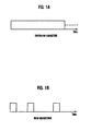
- Figs. 1A and 1B show a continuous signal and a burst signal in Digital Video Broadcasting-Return Channel via Satellite (DVB-RCS).
- DVD-RCS Digital Video Broadcasting-Return Channel via Satellite
- Fig. 2A shows a frequency hopping in the DVB-RCS.
- Fig. 2B shows a gain control method of the burst signal using a single-tone pilot signal.
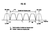
- Fig. 2C shows a gain control method of a burst signal using a multi-tone pilot signal in accordance with an embodiment of the present invention.
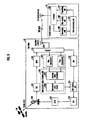
- Fig. 3 shows a gain control apparatus of the burst signal in the interactive satellite communication system in accordance with an embodiment of the present invention.
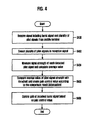
- Fig. 4 is a flowchart describing a gain control method of the burst signal in a gap filler in accordance with an embodiment of the present invention.
- Fig. 2A shows a frequency hopping in Digital Video Broadcasting-Return Channel via Satellite (DVB-RCS) and Fig. 2B shows a gain control method of a burst signal using a single-tone pilot signal.
- Fig. 2C shows a gain control method of the burst signal using a multi-tone pilot signal in accordance with an embodiment of the preset invention.
- the burst signal may be transmitted by inserting a sirigle-tone pilot signal shown in Fig. 2B , thus causing a problem as fellows.
- each frequency component halving different time differences due to effects of the multi-path inside the tunnel arrives at destinations including the gap filler and the mobile terminal. That is, it is possible to have fadings which are different from each other between frequency components even in the same signal.
- Coherence bandwidth (Bc) is the maximum bandwidth between frequency components having the same time delay.
- a narrowband system represent a system using a bandwidth narrower than the coherence bandwidth and a wideband system represents a system using a .bandwidth wider than the coherence bandwidth.
- a frequency band .of one burst signal is smaller than coherence bandwidth but a band for frequency hopping is 20MHz larger than the standard such that a system for improving resources through fast frequency hopping can be realized.
- the fading of the burst signal and pilot signal transmitted from the terminal may be different due to the frequency elective fading.
- the present invention uses a multi-tone pilot signal shown in Fig. 2C .
- the terminal when the terminal transmits the burst signal to the gap filler installed inside the tunnel, as shown in Fig. 2C , the terminal transmits the burst signal, by inserting a plurality of pilot signals.
- the multi-tone signal and divers modulation signals may be used as the pilot signal.
- the present invention inserts a plurality of pilot signals located in a frequency neighboring to a. use frequency band 210 of the terminal, i.e., upper and lower neighboring frequencies 211 and 212, with the burst signal.
- a plurality of pilot signals may be located in upper and lower parts symmetrically to a central location f 0 of the terminal use frequency band 210, as shown in Equation 1. According to embodiments, it is possible to locate a plurality of pilot signals symmetrically to an upper or lower band outside the terminal use frequency band 210 under the condition that precise signal filtering is required.
- Frequency of a couple of pilot signals f 0 ⁇ 2.5 ⁇ BW
- Frequency of two couples of pilot signals f 0 ⁇ 2.5 + f 0 ⁇ 3.5 ⁇ BW
- f 0 represents the central location, i.e., a central frequency, of the terminal use frequency band 210 and the central BW represents a use frequency band of a terminal 1 channel.
- the gap filler compensates for the gain of the burst signal using the transmitted pilot signals. Accordingly, the present invention can efficiently compensate for the signal attenuation between a train running at high-speed in a dead zone such as a tunnel and the gap filler inside the tunnel.
- Fig. 3 shows a gain control apparatus of the burst signal in the interactive satellite communication system in accordance with an embodiment of the present invention.
- the interactive satellite communication system provides an interactive satellite communication service by interaction of a terminal located at a moving object, i.e., a mobile terminal 30, a gap filler 32, and a satellite 34.
- a terminal located at a moving object i.e., a mobile terminal 30, a gap filler 32, and a satellite 34.
- a burst signal is transmitted from the mobile terminal 30 to the gap filler 32 will be described.
- the mobile terminal 30 additionally transmits a plurality of pilot signals with the burst signal to the gap filler 32.
- the pilot signal has a frequency neighboring to the use frequency band, i.e., the terminal use band, which is allocate to the mobile terminal.
- the pilot signal is a kind of a tone signal as a continuous signal which continuously exists on a time: axis.
- the gap filler 32 receives a reception signal including the burst signal and the pilot signal from the mobile terminal 30, and compensates for the gain of the burst signal using the pilot signal.
- the mobile terminal 30, which is a terminal located at the moving object, e.g., a. subway and a high-speed train, will be described in detail.
- the mobile terminal 30, as shown in Fig. 3 includes a data processing unit 300, a transmitting unit 301, a pilot creating unit 302, a triplexer 303, and a deceiving unit 304.
- the mobile terminal 30 transmits the signal to the gap filler 32 or receivers and processes the signal transmitted from the gap filler 32.
- the transmitting unit 301, the pilot creating unit 302, and the triplexer 303 corresponding to a multiplexing unit transmit the pilot signal to control the gain of the burst signal in the satellite dead zone but does not finally control the gain of the burst signals.
- the binding of these constituent elements may be the gain control apparatus of the burst signal in the mobile terminal 30.
- Each constituent element will be described hereinafter.
- the data processing unit 300 transmits transmission data received from or selected by the user to the transmitting unit 301, or processes the reception data recovered in the receiving unit 304 and provides the reception data to the user. Subsequently, the transmitting unit 301 creates a burst signal on the transmission data transmitted from the data processing unit 300.
- the pilot creating unit 302 creates a plurality of pilot signals to be transmitted with the burst signal created in the transmitting unit 301. That is, the pilot creating unit 302 creates and inserts a plurality of pilot signals into the neighboring frequency of the use frequency band, i.e., the terminal use band.
- the triplexer 303 multiplexes the burst signal created in the transmitting unit 301 and the pilot signal created in the pilot creating unit 302 and transmits t.he burst signal and the pilot signal to the gap filler 32.
- the triplexer 303 transmits the burst signal and the pilot signal from the mobile terminal 30 to the gap filler 32, the triplexer 303 corresponds to the multiplexing unit.
- the triplexer 303 of the mobile terminal 30 receives the data transmitted from the gap filler 32 and transmits the data to the receiving unit 304.
- the data processing unit 300 processes and provides the transmitted reception data to the user.
- the gap filler 32 will be described in detail hereinafter.
- the gap filler 32 includes a triplexer 321, a low noise amplifier (LNA) 322, a pi.lot detecting unit 323, a gain control value creating unit 324, a gain control unit 325, an up-converter (U/C) 326, solid state power amplifiers (SSPA) 327 and 332, a satellite transmitting and receiving antenna 330, and a down-converter (D/C) 331.
- the gap filler 32 receives the signal from the mobile terminal 30, controls a gain and relays the signal to the satellite 34, or relays the signal transmitted from the satellite 34 to the mobile terminal 30.
- the binding of these constituent elements may be called the gain control apparatus of the burst signal in the gap filler 32.
- gap filler 32 receives the signal transmitted from the mobile terminal 30, controls the gain and transmits the signal to the satellite 34 will be described.
- the triplexer 321 divides the reverse signal received through the gap filler antenna 320, i.e., the reverse signal transmitted from the terminal to the satellite, into a pilot signal band, i.e., a multi-tone pilot signal, and a burst signal. Subsequently, the triplexer 321 outputs the pilot signal band to the pilot detecting unit 323 and the burst signal to the low noise amplifier 322. In this case, the triplexer 321 corresponds to a signal dividing unit. Also, the triplexer 321 may relay the signal transmitted from the satellite 34 to the mobile terminal 30.
- the pilot detecting unit 323 includes a plurality of pilot detectors, individually detects each pilot signal included in the multi-tone pilot signal, and transmits the pilot signal to the gain control value creating unit 324.
- the gain control value creating unit .324 includes an average value calculator 3241 and a gain control value creator 3242.
- the average value calculator 3241 measures signal strength of each pilot signal detected in the pilot detecting unit 323 and calculates an .average value of the signal strength.
- the gain control value creator 3242 compares the calculated pilot signal strength average value with a predetermined threshold, and creates a gain control value of the burst signal according to the comparison result, i.e., attenuation.
- the gain control unit 325 controls the gain of the burst signal outputted from the low noise amplifier 322 basted on the gain control value created in the gain control value creating unit 324.
- the low noise amplifier 322 removes and amplifiers the noise of the burst signal divided through the triplexer 321.
- the SSPA 327 amplifiers the frequency up-converted burst signal.
- the amplified burst signal is transmitted t.o the satellite 34 through the satellite transmitting and receiving antenna 330.
- gap filler 32 transmits the signal transmitted from the satellite 34 to the mobile terminal 30.
- the SEPA 332 When the down-converter 331 performs frequency downconversion on the data signal received through the satellite transmitting and receiving antenna 330, the SEPA 332 amplifies the frequency down-converted data signal. The amplified data signal is transmitted to the mo.bile terminal 30 through the triplexer 321 and the gap filler antenna 320.
- Fig. 4 is a flowchart describing a gain control method of the burst signal in the gap filler in accordance with an embodiment of the present invention and shows the gain control method performed in the gap filler.
- the gap filler receives a signal including the burst signal and a plurality of pilot signals from the mobile terminal located at the moving object.
- the gap filler detects a plurality of pilot signals, i.e., multi-tone pilot signals, in the reception signal at step S402, measures signal strength of each detected pilot signal, and calculates an average value of the measured signal strength at step S404.
- a plurality of pilot signals i.e., multi-tone pilot signals
- the gap filler compares the average value of the pilot signal strength with the pre-determined threshold and creates a gain control value of the burst signal according to the comparison result, i.e., the attenuation, at step S406.
- the gap filler controls the gain of the burst signal received with the burst signal, i.e., the pilot signal, based on the c.reated gain control value at step S408. Accordingly, the gap filler compensates fo.r the signal attenuation in the fading environment such as the tunnel.
- the gap filler located at the dead zone such as the tunnel detects a plurality of pilot signals from the terminal located at the moving object and controls the gain of the burst signal using the pilot signals. Accordingly, the present invention can prevent deterioration of the performance caused by signal attenuation inside the tunnel.
- DVD-RCS Digital Video Broadcasting-Return Channel via Satellite
- the present invention can remarkably compensate for the signal attenuation between the gap .filler installed inside the tunnel and the terminal in the train traveling at high-speed.
- the technology of the present invention can be realized as a grogram.
- a code and a code segment forming the program can be easily inferred from a computer programmer of the related field.
- the realized program is stored in a computer-readable recording medium, i.e., information storing media, and is read and operated by the computer, thereby realizing the method of the present invention.
- the recording medium includes all types of recording media which can be read by the computer.
Landscapes
- Engineering & Computer Science (AREA)
- Signal Processing (AREA)
- Physics & Mathematics (AREA)
- Astronomy & Astrophysics (AREA)
- General Physics & Mathematics (AREA)
- Radio Relay Systems (AREA)
- Control Of Amplification And Gain Control (AREA)
- Cable Transmission Systems, Equalization Of Radio And Reduction Of Echo (AREA)
- Mobile Radio Communication Systems (AREA)
Abstract
Description
- T.he present invention claims priority of Korean Patent Application No.
10-2007-0132297 - The present Invention relates to an apparatus and method for controlling a gain of a burst signal in an interactive communication system; and, more particularly, to an apparatus and method for controlling a gain of a burst signal in an interactive communication system which can efficiently compensate for signal attenuation in a frequency selective fading environment such as a tunnel by additionally transmitting a plurality of pilot signals with the burst signal in a mobile terminal and compensating for the signal attenuation of the burst signal by using a plurality of received pilot signals in a repeater in case where a communication service such as a satellite communication service is provided by installing a gap filler on a dead zone such as a tunnel.
- This work was supported by the IT R&D program for MIC/IITA [2006-S-020-02, "Development of Satellite and Terrestrial Convergence Technology for Internet Service on High-speed Mobile Vehicles"].
- Generally, a satellite communication system transmits a continuous signal based on Digital Video Broadcasting - Satellite (DVB-S) on a path from a satellite to a terminal, i.e., a down-link, and transmits a burst signal based on Digital Video Broadcasting-Return Channel via Satellite (DVB-RCS) standard on a path from the terminal to the satellite, i.e., an up-link,
- Referring to
Fig. 1A , Time Division Multiplexing (TDM) signal transmitted from the satellite to the terminal is a. signal continuously existing on a time axis, i.e., a continuos signal. The strength of the inputted signal is detested and compared with that of a reference signal. Signal attenuation can be compensated for through an Automatic Gain Control (AGC) method using general feedback of increasing the strength of the signal when the strength of the inputted signal is smaller than that of the reference signal, and decreasing the strength of the signal when the strength of the inputted signal is smaller than that of the reference signal. - On the contrary, preferring to
Fig. 1B , a Time Division Multiple Access (TDMA) signal transmitted from the terminal to the satellite corresponds to a burst signal which does not continuously exist on a time axis due to a short signal length Although the TDMA signal appears randomly, it is not possible to compensate for the TDMA signal by the AGC method using she general feedback due to the short signal length. - In a conventional method for solving the problem, the gain can be controlled using a preamble in a receiving part by transmitting a burst signal whose preamble length is increased as much as an AGC response time. However, a problem is that efficiency of data transmission deceases due to unnecessary increase of the preamble length.
- Although direct communication between the satellite and the terminal is general in the satellite communication system, a repeater, which is called a gap filler hereinafter, is used for normal communication in an area where direct communication between the satellite and the terminal is not possible, e.g., a tunnel or an underground.
- Generally, satellite communication is performed under a status where line of sight (LOS) is secure. Some satellite broadcasting such as a satellite DMB recently applies a gap filler technology to deceive satellite broadcasting under a. Non-LOS (NLOS) environment.
- In more detail, the gap filler located inside the tunnel receives a Ku/Ka band signal, from the: satellite, performs frequency conversion into an ISM band on the Ku/Ka band signal, and transmits the concerted signal to the terminal. The terminal transmits the burst signal to the repeater based on the DVB-RCS standard. The terminal generally includes a set-top box for interactive satellite communication.
- Great signal attenuation is applied to the signal transmitted from the terminal to the repeater inside the tunnel, i.e., the burst signal, inside the tunnel. For example, when 2.4GHz band is used in the tunnel, great signal attenuation of about 100dB/km is generated in the signal generated between the repeater and the terminal.
- Therefore, the repeater is required to efficiently compensate for attenuation of the burst signal transmitted from the terminal and transmit the burst signal to the satellite such that the terminal inside the tunnel smoothy communicate with the satellite through the repeater.
- As described above, in case where a satellite communication service is provided through a gap f.iller, there is a problem that serous signal attenuation is generated in a. burst signal that a terminal located in a moving objects transmits to the repeater in a selective fading environment such as a tunnel. An object of the present invention is to solve the above problem.
- The objects of the present invention are not limited to the above-mentioned ones. Other objects and advantage of the present invention can be understood by the following description, and become apparent with reference to the embodiments of the present invention. Also, it is obvious to those skilled in the art to which the present invention pertains that the objects and advantages of the present invention can be realized by the means as claimed and combinations thereof.
- In order to realize the above object, when a communication service is provided by installing a repeater, i.e., a gap filler, in a dead zone such as a tunnel, the terminal located in the moving object additionally transmits a plurality of pilot signals with the burst signal. Accordingly, the repeater compensates for signal attenuation of the burst signal based on a plurality of received pilot signals.
- In accordance with an aspect of the present invention, there is provided an apparatus for controlling a gain of a burst signal in a mobile terminal, including: a transmitting unit for creating a burst signal on transmission data.; a pilot cresting unit for creating a plurality of pilot signals outside a use frequency band of the mobile terminal; and a multiplexing unit for multiplexing and transmitting the burst signal and the pilot signal to a gap filler.
- In accordance with another aspect of the present invention, there is provided an apparatus for controlling a gain of a burst signal in a gap filler, including: a signal dividing unit for receiving a reverse signal from a mobile terminal and dividing the reverse signal into a pilot signal band and a burst signal; a pilot detecting unit for individually detecting each pilot signal included in the pilot signal band; a gain control value creating unit for creating a gain control value of the burst signal using signal strength of the detected pilot signals; and a gain control unit for controlling the gain of the burst signal based on the created gain control value.
- In accordance with another aspect of the present invention, there is provided a method for controlling a gain of a burst signal in a mobile terminal, including: creating a burst signal on transmission data; creating a plurality of pilot signals located outside a use frequency band of the mobile terminal; and multiplexing and transmitting the burst signal and the pilot signal to a gap filler.
- In accordance with another aspect of the present invention, there is provided a method for controlling a gain of a burst signal in a gap filler, including: receiving a reverse signal from a mobile terminal and dividing the reverse signal into a pilot signal band and a burst signal; detecting each pilot signal included in the pilot signal band and measuring signal strength; creating a gain control value of the burst signal using the signal strength of the pilot signals; and controlling the gain of the burst signal using the created gain control value.
-
Figs. 1A and 1B show a continuous signal and a burst signal in Digital Video Broadcasting-Return Channel via Satellite (DVB-RCS). -
Fig. 2A shows a frequency hopping in the DVB-RCS. -
Fig. 2B shows a gain control method of the burst signal using a single-tone pilot signal. -
Fig. 2C shows a gain control method of a burst signal using a multi-tone pilot signal in accordance with an embodiment of the present invention. -
Fig. 3 shows a gain control apparatus of the burst signal in the interactive satellite communication system in accordance with an embodiment of the present invention. -
Fig. 4 is a flowchart describing a gain control method of the burst signal in a gap filler in accordance with an embodiment of the present invention. - The advantages, features and aspects of the invention will become apparent from the following description of the embodiments with reference to the accompanying drawings, which is set forth hereinafter. Therefore, those skilled in the field of this art of the present invention can embody the technological concept and scope of the invention easily. In addition, if it is considered that detailed description on a related art may obscure the points of the present invention, the detailed description will not be provided herein. The preferred embodiment of the present invention will be described in detail hereinafter with reference to the attached drawings.
-
Fig. 2A shows a frequency hopping in Digital Video Broadcasting-Return Channel via Satellite (DVB-RCS) andFig. 2B shows a gain control method of a burst signal using a single-tone pilot signal.Fig. 2C shows a gain control method of the burst signal using a multi-tone pilot signal in accordance with an embodiment of the preset invention. - In order to compensate for signal attenuation between the gap filler and the terminal inside the tunnel when the burst signal is transmitted to the gap filler installed inside the tunnel in the terminal, the burst signal may be transmitted by inserting a sirigle-tone pilot signal shown in
Fig. 2B , thus causing a problem as fellows. - When communication is performed using a gap filler in a satellite mobile communication under a fading environment such as a tunnel, e.g., a railway and a subway, each frequency component halving different time differences due to effects of the multi-path inside the tunnel arrives at destinations including the gap filler and the mobile terminal. That is, it is possible to have fadings which are different from each other between frequency components even in the same signal. Coherence bandwidth (Bc) is the maximum bandwidth between frequency components having the same time delay.
- A narrowband system represent a system using a bandwidth narrower than the coherence bandwidth and a wideband system represents a system using a .bandwidth wider than the coherence bandwidth.
- In the DVB-RCS, as shown in
Fig. 2A , it is clearly stated that a frequency band .of one burst signal is smaller than coherence bandwidth but a band for frequency hopping is 20MHz larger than the standard such that a system for improving resources through fast frequency hopping can be realized. - When a frequency band of a frame allocated to a return link gets wider than the coherence bandwidth, frequency selective fading appears.
- Therefore, when a
single pilot signal 201 shown inFig. 2B is used to automatically control the gain of the burst signal in the fading environment such as a tunnel, the fading of the burst signal and pilot signal transmitted from the terminal may be different due to the frequency elective fading. - In this case, in performance of burst automatic gain controls (AGC) using a single pilot signal, there is a possibil.ity that the gain is not controlled enough through the burst AGC in case where the inputted burst signal is small, and the inputted pilot signal is large. Reve.rsely, the same problem may occur in case where the pilot signal is small and the burst signal is large.
- Therefore, in order to overcome frequency selective fading inside the tunnel, the present invention uses a multi-tone pilot signal shown in
Fig. 2C . - In the present invention, when the terminal transmits the burst signal to the gap filler installed inside the tunnel, as shown in
Fig. 2C , the terminal transmits the burst signal, by inserting a plurality of pilot signals. The multi-tone signal and divers modulation signals may be used as the pilot signal. - That is, the present invention inserts a plurality of pilot signals located in a frequency neighboring to a.
use frequency band 210 of the terminal, i.e., upper and lowerneighboring frequencies - A plurality of pilot signals may be located in upper and lower parts symmetrically to a central location f0 of the terminal
use frequency band 210, as shown inEquation 1. According to embodiments, it is possible to locate a plurality of pilot signals symmetrically to an upper or lower band outside the terminaluse frequency band 210 under the condition that precise signal filtering is required.
where f0 represents the central location, i.e., a central frequency, of the terminaluse frequency band 210 and the central BW represents a use frequency band of aterminal 1 channel. - In the present invention, when the terminal transmits a plurality of pilot signals with the burst signal, the gap filler compensates for the gain of the burst signal using the transmitted pilot signals. Accordingly, the present invention can efficiently compensate for the signal attenuation between a train running at high-speed in a dead zone such as a tunnel and the gap filler inside the tunnel.
-
Fig. 3 shows a gain control apparatus of the burst signal in the interactive satellite communication system in accordance with an embodiment of the present invention. - The interactive satellite communication system provides an interactive satellite communication service by interaction of a terminal located at a moving object, i.e., a
mobile terminal 30, agap filler 32, and asatellite 34. A case that the burst signal is transmitted from themobile terminal 30 to thegap filler 32 will be described. - The
mobile terminal 30 additionally transmits a plurality of pilot signals with the burst signal to thegap filler 32. The pilot signal has a frequency neighboring to the use frequency band, i.e., the terminal use band, which is allocate to the mobile terminal. The pilot signal is a kind of a tone signal as a continuous signal which continuously exists on a time: axis. Subsequently, thegap filler 32 receives a reception signal including the burst signal and the pilot signal from themobile terminal 30, and compensates for the gain of the burst signal using the pilot signal. - The
mobile terminal 30, which is a terminal located at the moving object, e.g., a. subway and a high-speed train, will be described in detail. - The
mobile terminal 30, as shown inFig. 3 , includes adata processing unit 300, a transmittingunit 301, apilot creating unit 302, atriplexer 303, and a deceivingunit 304. Themobile terminal 30 transmits the signal to thegap filler 32 or receivers and processes the signal transmitted from thegap filler 32. The transmittingunit 301, thepilot creating unit 302, and thetriplexer 303 corresponding to a multiplexing unit transmit the pilot signal to control the gain of the burst signal in the satellite dead zone but does not finally control the gain of the burst signals. However, since the transmittingunit 301, thepilot creating unit 302, and thetriplexer 303 perform a part of the entire procedure of the burst signal gain control, the binding of these constituent elements may be the gain control apparatus of the burst signal in themobile terminal 30. Each constituent element will be described hereinafter. - The
data processing unit 300 transmits transmission data received from or selected by the user to the transmittingunit 301, or processes the reception data recovered in the receivingunit 304 and provides the reception data to the user. Subsequently, the transmittingunit 301 creates a burst signal on the transmission data transmitted from thedata processing unit 300. - Meanwhile, the
pilot creating unit 302 creates a plurality of pilot signals to be transmitted with the burst signal created in the transmittingunit 301. That is, thepilot creating unit 302 creates and inserts a plurality of pilot signals into the neighboring frequency of the use frequency band, i.e., the terminal use band. - Subsequently, the
triplexer 303 multiplexes the burst signal created in the transmittingunit 301 and the pilot signal created in thepilot creating unit 302 and transmits t.he burst signal and the pilot signal to thegap filler 32. When thetriplexer 303 transmits the burst signal and the pilot signal from themobile terminal 30 to thegap filler 32, thetriplexer 303 corresponds to the multiplexing unit. - The
triplexer 303 of themobile terminal 30 receives the data transmitted from thegap filler 32 and transmits the data to the receivingunit 304. Thedata processing unit 300 processes and provides the transmitted reception data to the user. - The
gap filler 32 will be described in detail hereinafter. - The
gap filler 32, as shown inFig. 3 , includes atriplexer 321, a low noise amplifier (LNA) 322, a pi.lot detecting unit 323, a gain controlvalue creating unit 324, again control unit 325, an up-converter (U/C) 326, solid state power amplifiers (SSPA) 327 and 332, a satellite transmitting and receivingantenna 330, and a down-converter (D/C) 331. Thegap filler 32 receives the signal from themobile terminal 30, controls a gain and relays the signal to thesatellite 34, or relays the signal transmitted from thesatellite 34 to themobile terminal 30. - Since the
triplexer 321, thepilot detecting unit 323, the gain controlvalue creating unit 324, and thegain control unit 325 control the gain of the burst signal using a reverse signal transmitted from themobile terminal 30, the binding of these constituent elements may be called the gain control apparatus of the burst signal in thegap filler 32. - A case that the
gap filler 32 receives the signal transmitted from themobile terminal 30, controls the gain and transmits the signal to thesatellite 34 will be described. - The
triplexer 321 divides the reverse signal received through thegap filler antenna 320, i.e., the reverse signal transmitted from the terminal to the satellite, into a pilot signal band, i.e., a multi-tone pilot signal, and a burst signal. Subsequently, thetriplexer 321 outputs the pilot signal band to thepilot detecting unit 323 and the burst signal to thelow noise amplifier 322. In this case, thetriplexer 321 corresponds to a signal dividing unit. Also, thetriplexer 321 may relay the signal transmitted from thesatellite 34 to themobile terminal 30. - The
pilot detecting unit 323 includes a plurality of pilot detectors, individually detects each pilot signal included in the multi-tone pilot signal, and transmits the pilot signal to the gain controlvalue creating unit 324. - The gain control value creating unit .324 includes an
average value calculator 3241 and a gaincontrol value creator 3242. Theaverage value calculator 3241 measures signal strength of each pilot signal detected in thepilot detecting unit 323 and calculates an .average value of the signal strength. The gaincontrol value creator 3242 compares the calculated pilot signal strength average value with a predetermined threshold, and creates a gain control value of the burst signal according to the comparison result, i.e., attenuation. - The
gain control unit 325 controls the gain of the burst signal outputted from thelow noise amplifier 322 basted on the gain control value created in the gain controlvalue creating unit 324. Thelow noise amplifier 322 removes and amplifiers the noise of the burst signal divided through thetriplexer 321. - When the up-
converter 326 up-converts the frequency of the burst signal after controlling the gain through thegain control unit 325, theSSPA 327 amplifiers the frequency up-converted burst signal. The amplified burst signal is transmitted t.o thesatellite 34 through the satellite transmitting and receivingantenna 330. - A case that the
gap filler 32 transmits the signal transmitted from thesatellite 34 to themobile terminal 30 will be described hereinafter. - When the down-
converter 331 performs frequency downconversion on the data signal received through the satellite transmitting and receivingantenna 330, theSEPA 332 amplifies the frequency down-converted data signal. The amplified data signal is transmitted to themo.bile terminal 30 through thetriplexer 321 and thegap filler antenna 320. -
Fig. 4 is a flowchart describing a gain control method of the burst signal in the gap filler in accordance with an embodiment of the present invention and shows the gain control method performed in the gap filler. - At step S400, the gap filler receives a signal including the burst signal and a plurality of pilot signals from the mobile terminal located at the moving object.
- The gap filler detects a plurality of pilot signals, i.e., multi-tone pilot signals, in the reception signal at step S402, measures signal strength of each detected pilot signal, and calculates an average value of the measured signal strength at step S404.
- The gap filler compares the average value of the pilot signal strength with the pre-determined threshold and creates a gain control value of the burst signal according to the comparison result, i.e., the attenuation, at step S406.
- Subsequently, the gap filler controls the gain of the burst signal received with the burst signal, i.e., the pilot signal, based on the c.reated gain control value at step S408. Accordingly, the gap filler compensates fo.r the signal attenuation in the fading environment such as the tunnel.
- In the present invention, when a communication system, specially, a satellite communication system, provides a satellite communication service using the burst signal following a Digital Video Broadcasting-Return Channel via Satellite (DVB-RCS) standard, the gap filler located at the dead zone such as the tunnel detects a plurality of pilot signals from the terminal located at the moving object and controls the gain of the burst signal using the pilot signals. Accordingly, the present invention can prevent deterioration of the performance caused by signal attenuation inside the tunnel.
- In particular, when the high-speed train passes through the dead zone of the frequency selective fading environment such as the tunnel, the present invention can remarkably compensate for the signal attenuation between the gap .filler installed inside the tunnel and the terminal in the train traveling at high-speed.
- As described above, the technology of the present invention can be realized as a grogram. A code and a code segment forming the program can be easily inferred from a computer programmer of the related field. Also, the realized program is stored in a computer-readable recording medium, i.e., information storing media, and is read and operated by the computer, thereby realizing the method of the present invention. The recording medium includes all types of recording media which can be read by the computer.
- While the present invention has been described with respect to the specific embodiments, it will be apparent to those skilled in the art that various changes and modifications may be made without departing from the spirit and scope of the invention as defined in the following claims.
Claims (14)
- An apparatus for controlling a gain of a. burst signal in a mobile terminal, comprising:a transmitting means for creating a burst signal on transmission data;a pilot creating means for creating a plurality of pilot signals outside a use frequency band of the mobile terminal; anda multiplexing means for multiplexing and transmitting the burst signal and the pilot signal to a gap filler.
- The apparatus of claim 1, wherein the pilot creating means creates a plurality of pilot signals which are respectively located at upper and lower bands of the use frequency band of the mobile terminal.
- The apparatus of claim 2, wherein the pilot signals are located at upper and lower bands symmetrically to the central location of the use frequency band of the mobile terminal.
- The apparatus of claim 1, 2,or3, wherein the pilot signals are multi-tone signals
- The apparatus of one of claims 1 to 4, wherein the gap filler is a gap filler installed in a satellite dead zone.
- An apparatus for controlling a gain of a burst signal in a gap filler, comprising:a signal dividing means for receiving a reverse signal from a mobile terminal and dividing the reverse signal into a pilot signal band and a burst signal;a pilot detesting means for individually detecting each pilot signal included in the pilot signal band;a gain control value creating means for creating a gain control value of the burst signal using signal strength of the detected pilot signals; anda gain control means for controlling the gain of the burst signal based on the created gain control value.
- The apparatus of claim 6, wherein the gain control value creating means calculates a signal strength average value by measuring signal strength of the detected pilot signal, calculates attenuation by comparing the calculated signal strength average value with a predetermined threshold, and creates a gain control value of the burst signal according to the attenuation.
- The apparatus of claim 6 or 7, wherein the mobile terminal is a mobile terminal located at a satellite dead zone.
- The apparatus of claim 6, 7, or8, wherein the gap filler is a gap filler for satellite communication which is locate at the satellite dead zone.
- A method for controlling a gain of a burst signal in a mobile terminal, comprising:creating a burst signal on transmission data;creating a plurality of pilot signals located outside a use frequency band of the mobile terminal; andmultiplexing and transmitting the burst signal and the pilot signal to a gap filler.
- The method of claim 10, wherein the pilot signals respectively located at upper and lower bands of the use frequency band of the mobile terminal are created.
- The method of claim 11, wherein the pilot signals are located at the upper and lower bands symmetrically to the central location of the use frequency band of the mobile terminal.
- A method for controlling a gain of a burst signal in a gap filler, comprising:receiving a reverse signal from a mobile terminal and dividing the reverse signal into a pilot signal band and a burst signal;detecting each pilot signal included in the pilot signal band and measuring signal strength;creating a gain control value of the burst signal using the signal strength of the pilot signals; andcontrolling the gain of the burst signal using the created gain control value.
- The method of claim 13, wherein said creating a gain control value of the burst signal includes:calculating a signal strength average value of the pilot signals;calculating attenuation by comparing the calculated signal strength average value with a predetermined threshold; andcreating a gain control value of the burst signal according to the attenuation.
Applications Claiming Priority (1)
| Application Number | Priority Date | Filing Date | Title |
|---|---|---|---|
| KR1020070132297A KR100940604B1 (en) | 2007-12-17 | 2007-12-17 | Gain Control Device and Method of Burst Signal in Bidirectional Communication System |
Publications (2)
| Publication Number | Publication Date |
|---|---|
| EP2075933A2 true EP2075933A2 (en) | 2009-07-01 |
| EP2075933A3 EP2075933A3 (en) | 2012-04-18 |
Family
ID=40526608
Family Applications (1)
| Application Number | Title | Priority Date | Filing Date |
|---|---|---|---|
| EP08158957A Withdrawn EP2075933A3 (en) | 2007-12-17 | 2008-06-25 | Apparatus and method for controlling gain of burst signal in interactive communication system |
Country Status (2)
| Country | Link |
|---|---|
| EP (1) | EP2075933A3 (en) |
| KR (1) | KR100940604B1 (en) |
Family Cites Families (6)
| Publication number | Priority date | Publication date | Assignee | Title |
|---|---|---|---|---|
| FR2408943A1 (en) * | 1977-11-15 | 1979-06-08 | Thomson Csf | AUTOMATIC CONTROL DEVICE OF THE GAIN OF A RECEPTION CHANNEL, USED IN PARTICULAR IN SYSTEMS INCLUDING OPTICAL LINKS |
| US4403348A (en) * | 1981-09-21 | 1983-09-06 | Bell Telephone Laboratories, Incorporated | Single sideband receiver with intersyllabic gain correction limit control |
| US4876741A (en) * | 1982-02-11 | 1989-10-24 | General Signal Corporation | Method of receiving a compressed composite signal |
| KR100546479B1 (en) * | 2003-05-14 | 2006-01-26 | 에스케이 텔레콤주식회사 | Optical Loss Compensation Device of Optical Repeater Using Pilot Signal and Its Method |
| KR100623485B1 (en) * | 2004-12-21 | 2006-09-13 | 한국전자통신연구원 | A receiving apparatus of orthogonal frequency division multiplex system and a demodulation method thereof |
| US7599711B2 (en) * | 2006-04-12 | 2009-10-06 | Adc Telecommunications, Inc. | Systems and methods for analog transport of RF voice/data communications |
-
2007
- 2007-12-17 KR KR1020070132297A patent/KR100940604B1/en not_active Expired - Fee Related
-
2008
- 2008-06-25 EP EP08158957A patent/EP2075933A3/en not_active Withdrawn
Also Published As
| Publication number | Publication date |
|---|---|
| EP2075933A3 (en) | 2012-04-18 |
| KR20090064919A (en) | 2009-06-22 |
| KR100940604B1 (en) | 2010-02-05 |
Similar Documents
| Publication | Publication Date | Title |
|---|---|---|
| EP1060567B1 (en) | Self-interference cancellation for relayed communication networks | |
| US6141534A (en) | Communication satellite system with dynamic downlink resource allocation | |
| EP1744502B1 (en) | Method for relaying data packets in the downlink in a wireless communication system | |
| US20070153734A1 (en) | Apparatus and method for transparent relay in multihop relay broadband wireless access (BWA) communication system | |
| US10312997B2 (en) | Method for reducing interference in a satellite communications network | |
| KR101151142B1 (en) | Method for establish uplink in mobile satellite communication system | |
| EP1320204B1 (en) | Method and apparatus using variations in power modulation to identify an interfering mobile terminal | |
| JPS60190035A (en) | Control system of satellite communication transmission power | |
| US6763006B1 (en) | Method and apparatus for controlling uplink transmission power within a satellite communication system | |
| US6009306A (en) | Hub communications satellite and system | |
| EP1999865B1 (en) | System for extending bi-directional satellite radio communications in tunnels | |
| US7953367B2 (en) | System and method for efficient frequency use in a hybrid multi-spot satellite broadcasting system | |
| EP2096771A2 (en) | Communication system using an aircraft as a relay | |
| EP1439641B1 (en) | Bi-directional transponder apparatus and method of operation | |
| KR100940604B1 (en) | Gain Control Device and Method of Burst Signal in Bidirectional Communication System | |
| EP2075934A2 (en) | Apparatus and method for controlling burst gain in bi-directional dead spot | |
| Patra et al. | Frequency diversity improvement factor for rain fade mitigation technique for 50–90 GHz in tropical region | |
| KR100837731B1 (en) | Apparatus and method for gain controlling of burst signal in interactive satellite telecommunication system | |
| JP2005295090A (en) | Satellite communication system and satellite communication apparatus | |
| JP7268749B2 (en) | wireless communication system | |
| US8027285B1 (en) | Method to eliminate frequency offset introduced in a network | |
| KR20080050927A (en) | Timing Synchronization Method in TMD-based Bidirectional Satellite Communication System | |
| US8081708B2 (en) | Reradiation apparatus for terrestrial digital broadcasting and method for reradiating terrestrial digital broadcasting | |
| KR100932927B1 (en) | Data relay method in wireless communication system | |
| US20140286453A1 (en) | Satellite communication having distinct low priority information broadcast into adjacent sub-regions |
Legal Events
| Date | Code | Title | Description |
|---|---|---|---|
| PUAI | Public reference made under article 153(3) epc to a published international application that has entered the european phase |
Free format text: ORIGINAL CODE: 0009012 |
|
| AK | Designated contracting states |
Kind code of ref document: A2 Designated state(s): AT BE BG CH CY CZ DE DK EE ES FI FR GB GR HR HU IE IS IT LI LT LU LV MC MT NL NO PL PT RO SE SI SK TR |
|
| AX | Request for extension of the european patent |
Extension state: AL BA MK RS |
|
| PUAL | Search report despatched |
Free format text: ORIGINAL CODE: 0009013 |
|
| AK | Designated contracting states |
Kind code of ref document: A3 Designated state(s): AT BE BG CH CY CZ DE DK EE ES FI FR GB GR HR HU IE IS IT LI LT LU LV MC MT NL NO PL PT RO SE SI SK TR |
|
| AX | Request for extension of the european patent |
Extension state: AL BA MK RS |
|
| RIC1 | Information provided on ipc code assigned before grant |
Ipc: H04H 60/78 20080101ALI20120314BHEP Ipc: H04H 40/90 20080101AFI20120314BHEP |
|
| 17P | Request for examination filed |
Effective date: 20121018 |
|
| AKX | Designation fees paid |
Designated state(s): AT BE BG CH CY CZ DE DK EE ES FI FR GB GR HR HU IE IS IT LI LT LU LV MC MT NL NO PL PT RO SE SI SK TR |
|
| STAA | Information on the status of an ep patent application or granted ep patent |
Free format text: STATUS: THE APPLICATION HAS BEEN WITHDRAWN |
|
| 18W | Application withdrawn |
Effective date: 20140818 |