EP2075890B1 - Procédé de régulation de fréquence rapide utilisant un réservoir électrique - Google Patents
Procédé de régulation de fréquence rapide utilisant un réservoir électrique Download PDFInfo
- Publication number
- EP2075890B1 EP2075890B1 EP07150456.7A EP07150456A EP2075890B1 EP 2075890 B1 EP2075890 B1 EP 2075890B1 EP 07150456 A EP07150456 A EP 07150456A EP 2075890 B1 EP2075890 B1 EP 2075890B1
- Authority
- EP
- European Patent Office
- Prior art keywords
- power
- wind turbine
- grid
- switching elements
- controllable switching
- Prior art date
- Legal status (The legal status is an assumption and is not a legal conclusion. Google has not performed a legal analysis and makes no representation as to the accuracy of the status listed.)
- Active
Links
- 238000000034 method Methods 0.000 title claims description 34
- 230000001105 regulatory effect Effects 0.000 claims description 39
- 238000010521 absorption reaction Methods 0.000 claims description 34
- 239000003990 capacitor Substances 0.000 claims description 19
- 238000010438 heat treatment Methods 0.000 claims description 6
- 230000003213 activating effect Effects 0.000 claims description 4
- 239000008236 heating water Substances 0.000 claims description 4
- XLYOFNOQVPJJNP-UHFFFAOYSA-N water Substances O XLYOFNOQVPJJNP-UHFFFAOYSA-N 0.000 description 3
- XUIMIQQOPSSXEZ-UHFFFAOYSA-N Silicon Chemical compound [Si] XUIMIQQOPSSXEZ-UHFFFAOYSA-N 0.000 description 2
- 230000001276 controlling effect Effects 0.000 description 2
- 238000013461 design Methods 0.000 description 2
- 238000004519 manufacturing process Methods 0.000 description 2
- 238000012261 overproduction Methods 0.000 description 2
- 230000008844 regulatory mechanism Effects 0.000 description 2
- 229910052710 silicon Inorganic materials 0.000 description 2
- 239000010703 silicon Substances 0.000 description 2
- 238000003860 storage Methods 0.000 description 2
- 238000013459 approach Methods 0.000 description 1
- 238000012937 correction Methods 0.000 description 1
- 238000013016 damping Methods 0.000 description 1
- 238000012986 modification Methods 0.000 description 1
- 230000004048 modification Effects 0.000 description 1
- 238000010248 power generation Methods 0.000 description 1
- 239000003381 stabilizer Substances 0.000 description 1
- 238000004804 winding Methods 0.000 description 1
Images
Classifications
-
- H—ELECTRICITY
- H02—GENERATION; CONVERSION OR DISTRIBUTION OF ELECTRIC POWER
- H02J—CIRCUIT ARRANGEMENTS OR SYSTEMS FOR SUPPLYING OR DISTRIBUTING ELECTRIC POWER; SYSTEMS FOR STORING ELECTRIC ENERGY
- H02J3/00—Circuit arrangements for ac mains or ac distribution networks
- H02J3/38—Arrangements for parallely feeding a single network by two or more generators, converters or transformers
-
- F—MECHANICAL ENGINEERING; LIGHTING; HEATING; WEAPONS; BLASTING
- F03—MACHINES OR ENGINES FOR LIQUIDS; WIND, SPRING, OR WEIGHT MOTORS; PRODUCING MECHANICAL POWER OR A REACTIVE PROPULSIVE THRUST, NOT OTHERWISE PROVIDED FOR
- F03D—WIND MOTORS
- F03D7/00—Controlling wind motors
- F03D7/02—Controlling wind motors the wind motors having rotation axis substantially parallel to the air flow entering the rotor
- F03D7/0272—Controlling wind motors the wind motors having rotation axis substantially parallel to the air flow entering the rotor by measures acting on the electrical generator
-
- F—MECHANICAL ENGINEERING; LIGHTING; HEATING; WEAPONS; BLASTING
- F03—MACHINES OR ENGINES FOR LIQUIDS; WIND, SPRING, OR WEIGHT MOTORS; PRODUCING MECHANICAL POWER OR A REACTIVE PROPULSIVE THRUST, NOT OTHERWISE PROVIDED FOR
- F03D—WIND MOTORS
- F03D7/00—Controlling wind motors
- F03D7/02—Controlling wind motors the wind motors having rotation axis substantially parallel to the air flow entering the rotor
- F03D7/028—Controlling wind motors the wind motors having rotation axis substantially parallel to the air flow entering the rotor controlling wind motor output power
- F03D7/0284—Controlling wind motors the wind motors having rotation axis substantially parallel to the air flow entering the rotor controlling wind motor output power in relation to the state of the electric grid
-
- F—MECHANICAL ENGINEERING; LIGHTING; HEATING; WEAPONS; BLASTING
- F05—INDEXING SCHEMES RELATING TO ENGINES OR PUMPS IN VARIOUS SUBCLASSES OF CLASSES F01-F04
- F05B—INDEXING SCHEME RELATING TO WIND, SPRING, WEIGHT, INERTIA OR LIKE MOTORS, TO MACHINES OR ENGINES FOR LIQUIDS COVERED BY SUBCLASSES F03B, F03D AND F03G
- F05B2270/00—Control
- F05B2270/30—Control parameters, e.g. input parameters
- F05B2270/337—Electrical grid status parameters, e.g. voltage, frequency or power demand
-
- Y—GENERAL TAGGING OF NEW TECHNOLOGICAL DEVELOPMENTS; GENERAL TAGGING OF CROSS-SECTIONAL TECHNOLOGIES SPANNING OVER SEVERAL SECTIONS OF THE IPC; TECHNICAL SUBJECTS COVERED BY FORMER USPC CROSS-REFERENCE ART COLLECTIONS [XRACs] AND DIGESTS
- Y02—TECHNOLOGIES OR APPLICATIONS FOR MITIGATION OR ADAPTATION AGAINST CLIMATE CHANGE
- Y02E—REDUCTION OF GREENHOUSE GAS [GHG] EMISSIONS, RELATED TO ENERGY GENERATION, TRANSMISSION OR DISTRIBUTION
- Y02E10/00—Energy generation through renewable energy sources
- Y02E10/70—Wind energy
- Y02E10/72—Wind turbines with rotation axis in wind direction
-
- Y—GENERAL TAGGING OF NEW TECHNOLOGICAL DEVELOPMENTS; GENERAL TAGGING OF CROSS-SECTIONAL TECHNOLOGIES SPANNING OVER SEVERAL SECTIONS OF THE IPC; TECHNICAL SUBJECTS COVERED BY FORMER USPC CROSS-REFERENCE ART COLLECTIONS [XRACs] AND DIGESTS
- Y02—TECHNOLOGIES OR APPLICATIONS FOR MITIGATION OR ADAPTATION AGAINST CLIMATE CHANGE
- Y02E—REDUCTION OF GREENHOUSE GAS [GHG] EMISSIONS, RELATED TO ENERGY GENERATION, TRANSMISSION OR DISTRIBUTION
- Y02E10/00—Energy generation through renewable energy sources
- Y02E10/70—Wind energy
- Y02E10/76—Power conversion electric or electronic aspects
Definitions
- the present invention relates to a method for fast regulation of the fundamental frequency of electrical power distributed on a power supply grid operationally connected to a wind turbine optionally forming part of a wind farm.
- the amount of electrical power fed into a power supply grid from a wind turbine is typically varied by pitching the rotor blades so that nominal power is generated at a given wind speed.
- pitching of rotor blades is a rather slow regulation mechanism.
- pitching of rotor blades will not be capable of compensating for sudden and strong gusts of wind.
- WO 99/50945 discloses an arrangement for dissipating electrical power from a wind turbine generator in case the amount of generated power exceeds the nominal production of the wind turbine generator.
- electrical power may be dissipated in a dump load, said dump load comprising resistors, capacitors, inductors or a combination thereof.
- WO 99/50945 is concerned with using a dump load to "burn-off" output spikes caused by strong gusts in order to increase quality of the delivered power.
- WO 99/50945 addresses "burn-off" of electrical power exceeding, over a longer period of time, at nominal power level. If the amount of electrical power provided from a dominant wind turbine to a power supply grid exceeds a nominal power level over a long period of time the grid frequency of the electrical power distributed via the supply may unintentionally increase to a level significantly higher than the nominal grid frequency of the power supply grid in question.
- the nominal grid frequency may be for example 50 Hz or 60 Hz.
- WO2004/027959 A1 discloses a wind park with a power system stabilizer comprising a dump load for damping frequency deviations.
- the above-mentioned objects are complied with by providing, in a first aspect a method for regulating a grid frequency of electrical power of a power supply grid operationally connected to a stall or pitch regulated wind turbine while said stall or pitch regulated wind turbine remains connected to the power supply grid, the stall or pitch regulated wind turbine comprising a wind turbine generator adapted to convert wind energy to electrical energy, the method comprising the steps of
- regulation of a grid frequency is meant that if a measured grid frequency differs from a nominal grid frequency with more than a predetermined value regulation of the grid frequency is initiated by changing the amount of electrical power fed into the power supply grid from a wind turbine. In case a measured grid frequency is higher than the nominal grid frequency the amount of electrical power fed into the power supply grid is reduced, whereas in case a measured grid frequency is lower than the nominal grid frequency the amount of electrical power fed into the power supply grid is increased.
- the measured frequency is typically allowed to differ up to 0.4% from the nominal frequency before regulation thereof is initiated.
- the range within which the grid frequency is allowed to vary is normally denoted a dead band.
- a nominal grid frequency of 50 Hz is allowed to vary from 49.8 Hz to 50.2 Hz before regulation is initiated.
- a nominal grid frequency of 60 Hz is allowed to vary from 58.76 Hz to 60.24 Hz before regulation is initiated.
- the before-mentioned dead band of +/- 0.4% is just an example. Both a narrower and a wider dead band may also be applicable.
- a stall regulated wind turbine should be understood as a wind turbine where the rotor blades are mounted with a fixed angle to the rotor hub. At wind speeds below a value, v P max , corresponding to maximum power generation a laminar flow is obtained around the rotor blades. When wind speeds exceed v P max the flow around the rotor blades starts to detach from the blade and turbulence occur behind the rotor blade.
- a pitch regulated wind turbine should be understood as a wind turbine where the rotor blades, or parts thereof, may be pitched in or out of the wind in order to vary the wind power on the drive train of the wind turbine. However, due to the heavy masses involved, the time constants involved in pitching the rotor blades is too long in order to compensate for sudden gusts of wind.
- the electrical power produced by the stall regulated wind turbine remains unchanged. However, the electrical power launched into the power supply grid is reduced by the amount of power absorbed in the power absorption means.
- the wind power may be adjusted by pitching the rotor blades, or parts thereof, in and out of the wind. Hence, the amount of power absorbed depends on the speed of the blade pitching.
- the term power absorption means should be interpreted broadly.
- the power absorption means may involve a device for dissipation/burning off of electrical power only.
- the power absorption means may involve a device capable of storing electrical energy for later use. Such later use may involve heating of for example water or it may involve grid frequency regulation in case the wind turbine is unable to generate sufficient power to increase the grid frequency.
- a strategy involving pitching of rotor blades in combination with an absorption of power in the power absorption means may also be followed.
- the size of the wind turbine may vary from some hundreds of kW to several MW, and the wind turbine may be positioned on land or at sea as an off-shore wind turbine.
- the power absorption means and the power regulation means form part of the stall or pitch regulated wind turbine.
- the power absorption means and the power regulation means may be installed in the nacelle of the wind turbine, or they may be positioned on or near the foundation of the wind turbine.
- the power absorption means may comprise one or more power resistors, said one or more power resistors being individually electrically accessible, or accessible in groups comprising a plurality of power resistors.
- said power resistors may be coupled in series or in parallel.
- the power absorption means may comprise one or more capacitors, said one or more capacitors being individually electrically accessible, or accessible in groups comprising a plurality of capacitors.
- the power absorption means comprises a plurality of capacitors, said capacitors may be coupled in series or in parallel.
- the one or more capacitors may be used for storage purposes.
- appropriate rectifier means such as a inverter with active switches, such as IGBT's, MOSFET or thyristors or a passive rectifier bridge, is required in order to rectify the generated AC power.
- the resistance and/or capacitance of the power absorption means may be variable so that the power absorption means may constitute a variable load.
- the size of the power absorption means may be within the range 5-50% of the rated capacity of the wind turbine. Preferably, the size may be within the range 10-30% of the rated capacity of the wind turbine.
- the power regulation means may comprise first and second controllable switching elements, said first and second controllable switching elements being activeable in order to absorb the predetermined amount of power in the power absorption means.
- Suitable control means adapted to control the first and second controllable switching elements may be provided as well.
- the first and second controllable switching elements may be arranged in an anti/parallel arrangement.
- the first and second controllable switching elements may comprise a first and a second thyristor, respectively, or a first and a second IGBT, respectively.
- other types of controllable silicon-based switching devices are also applicable.
- the method according to the first aspect of the present invention may further comprise the step of applying electrical power absorbed in the power absorption means for heating purposes, such as for heating water.
- Such heated water may be provided consumers connected to the power supply grid.
- a method for regulating a grid frequency of a power supply grid by varying the amount of electrical power fed into the supply grid from a wind turbine while still keeping said wind turbine running at optimal working conditions.
- the wind turbine generated electrical power exceeding the amount of electrical power to be launched into the supply grid is absorbed in appropriate absorption means, optionally for later use.
- the electrical power exceeding the amount to be launched into the supply grid is stored for later use, such later use may involve grid frequency regulation in situations where the wind turbine is unable to generate sufficient power.
- the present invention relates to a method for regulating a grid frequency of electrical power of a power supply grid operationally connected to a stall or pitch regulated wind turbine while said stall or pitch regulated wind turbine remains connected to the power supply grid, the stall or pitch regulated wind turbine comprising a wind turbine generator, the method comprising the step of varying an amount of electrical power absorbed in a wind turbine dump load thereby regulating the grid frequency of the electrical power of the power supply grid, wherein the wind turbine dump load and the power regulation means form part of the stall or pitch regulated wind turbine.
- Stall or pitch regulated wind turbines as defined previously also apply in the second aspect of the present invention.
- the size of the wind turbine may vary from some hundreds of kW to several MW.
- regulation of a grid frequency is meant that if a measured grid frequency differs from a nominal grid frequency with more than a predetermined value regulation of the grid frequency is initiated by changing the amount of electrical power fed into the power supply grid from a wind turbine. Power exceeding the amount to be launched into the supply grid is absorbed in the wind turbine dump load. The absorbed electrical power may optionally be saved for later use. Such later use may involve heating of water or grid frequency regulation.
- the measured frequency is allowed to differ up to 0.4% from the nominal frequency before regulation thereof is initiated.
- a nominal grid frequency of 50 Hz is allowed to vary from 49.8 Hz to 50.2 Hz before regulation is initiated.
- a nominal grid frequency of 60 Hz is allowed to vary from 58.76 Hz to 60.24 Hz before regulation is initiated.
- the wind turbine dump load may comprise one or more power resistors, said one or more power resistors being individually electrically accessible, or accessible in groups comprising a plurality of power resistors.
- the wind turbine dump load may comprise one or more capacitors, said one or more capacitors being individually electrically accessible, or accessible in groups comprising a plurality of capacitors.
- the method according to the second aspect of the present invention may further comprise the steps of providing power regulation means adapted to regulate the amount of power being absorbed in the wind turbine dump load, and activating said power regulation means in order to absorb a predetermined amount of power in the wind turbine dump load so as to regulate the grid frequency of the electrical power of the power supply grid operationally connected to the wind turbine.
- the wind turbine dump load and the power regulation means form part of the stall or pitch regulated wind turbine.
- the power regulation means may be implemented following the design route discussed in connection with the first aspect of the present invention.
- the power absorption means and the power regulation means may be implemented following the design route outlined in connection with the first aspect of the present invention.
- the power absorption means and the power regulation means may form part of a bus bar collector inserted between the wind turbine farm and the power supply grid.
- the present invention relates to an on-the-fly method for regulating a grid frequency of a power supply grid, and, at the same time, maintaining optimal working conditions of a stall or pitch regulated wind turbine operationally connected to the power supply grid.
- the grid frequency accidentally increases to an unacceptable level correction measures should be initiated in order to protect consumer electronics connected to the power supply grid.
- the grid frequency of the power supply grid can be lowered by lowering the amount of electrical power provided to the power supply grid.
- electrical power exceeding the amount to be delivered to the power supply grid is absorbed in some sort of electrical power reservoir, optionally for later use.
- the method according to the present invention is performed while keeping the stall or pitch regulated wind turbine connected to the power supply grid.
- the electrical power produced by the stall regulated wind turbine remains unchanged, but the electrical power launched into the power supply grid is reduced by the amount of power absorbed in the power reservoir, whereas the pitch regulated wind turbine can adjust the wind power by pitching the rotor blades, or parts thereof, in and out of the wind.
- the amount of power absorbed depends on the speed of the blade pitching.
- the pitch regulated wind turbine may be kept at maximal power production, i.e. not pitching the rotor blades for adjusting the wind power.
- the electrical power not launched into the power supply grid may be stored or dissipated in the power reservoir.
- the present invention will be described with reference to a single wind turbine being used for regulating a grid frequency. It should be noted, however, that the present invention can be implemented on a wind turbine farm level as well. In case the present invention is implemented on a wind turbine farm level the power reservoir and an appropriate power regulation device for controlling the power flow to the power reservoir can form part of a bus bar collector inserted between the wind turbine farm and the power supply grid.
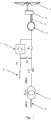
- the arrangement involves a wind turbine which as a minimum comprises a set of rotatably arranged rotor blades 1 operatively coupled to a wind turbine generator 2 through a drive train 3.
- the drive train 4 optionally involves a gear box 4.
- the arrangement further comprises a resistive or a capacitive power reservoir 8 for absorbing electrical power exceeding the amount of power to be delivered to the power supply grid 5, optionally through a three phase grid transformer 6.
- the grid transformer 6 transforms the wind turbine generator voltage, typically 690 V, to an appropriate grid voltage level, such as for example 20 kV.
- the windings of the grid transformer depicted in Fig. 1 are implemented as a star/delta connection, but other types of connections are also applicable.
- a circuit breaker CB is provided for disconnecting the wind turbine from the power supply grid if demands so require.
- the amount of electrical power to be absorbed in the power reservoir 8 is controlled by a number of controllable switching elements.
- the controllable switching elements which are arranged in an anti/parallel arrangement, form part of a power regulation module 7.
- the controllable switching elements typically involve a first and a second thyristor, or alternatively, a first and a second IGBT, respectively, or other types of silicon-based switching arrangements.
- Appropriate control means are provided for controlling the operation of the first and second controllable switching elements so that the wind turbine is maintained at optimal conditions even though only a portion of its generated electrical power is fed into the power supply grid.
- a number of contactors, K 1 , K 2 and K 3 are provided in order to couple the various elements of the arrangement in and/or out of operation.
- Fig. 1 The arrangement depicted in Fig. 1 is operated as follows in order to carry out the method according to the present invention.
- contactor K 1 and K 2 are both closed while contactor K 3 is open. Circuit breaker CB is closed as well. If the grid frequency increases to an undesired level contactor K 1 is closed and the controllable switching elements are activated in order to initiate absorption of electrical power in the power reservoir which, as previously mentioned, can be of resistive and/or capacitive nature. K 3 is used for during start-up of the wind turbine.
- the grid frequency is measured by appropriate sensor means, and the measured grid frequency is used as an input signal to a control module which is capable of generating appropriate control signals to the first and second controllable switching elements.
- the wind turbine generator can be operated at nominal working conditions even through only a portion of the generated electrical power can be fed into the power supply grid because the grid frequency needs to be lowered.
- the amount of electrical power exceeding the portion to the fed into the power supply grid is absorbed in a power reservoir, optionally for later use.
- the power reservoir is used for dissipating power using one or more power resistors.
- the power reservoir is used for storage purposes in that the power reservoir comprises a number of capacitors.
- appropriate rectifier means such as a inverter with active switches, such as IGBT's, MOSFET or thyristors or a passive rectifier bridge, is required in order to rectify the generated AC power.
- the size of the power reservoir is preferably within the range of 10-30% of the rated capacity of the wind turbine or wind turbine farm.
- Accumulated energy in the form of electrical power can for example be used for heating purposes, such as for heating water.
- accumulated electrical power can be used to increase the grid frequency in case the wind turbine or wind turbine farm is unable to generate sufficient power.
Landscapes
- Engineering & Computer Science (AREA)
- Life Sciences & Earth Sciences (AREA)
- Sustainable Development (AREA)
- Sustainable Energy (AREA)
- Chemical & Material Sciences (AREA)
- Combustion & Propulsion (AREA)
- Mechanical Engineering (AREA)
- General Engineering & Computer Science (AREA)
- Power Engineering (AREA)
- Control Of Eletrric Generators (AREA)
- Wind Motors (AREA)
Claims (17)
- Procédé pour réguler une fréquence de réseau d'une puissance électrique d'un réseau d'alimentation électrique ayant un convention de raccordement associé à celui-ci, le réseau d'alimentation électrique étant relié fonctionnellement à une éolienne à pas fixe ou à pas variable pendant ladite régulation de fréquence de réseau, l'éolienne à pas fixe ou à pas variable comprenant un aérogénérateur adapté pour transformer de l'énergie éolienne en énergie électrique, le procédé comprenant les étapes de- fourniture d'un moyen d'absorption de puissance adapté pour absorber la puissance électrique fournie par l'aérogénérateur ou fournie depuis le réseau d'alimentation électrique,- fourniture d'un moyen de régulation de puissance adapté pour réguler une quantité de puissance devant être absorbée dans le moyen d'absorption de puissance, et- activation du moyen de régulation de puissance afin d'absorber une quantité de puissance prédéterminée dans le moyen d'absorption de puissance et réguler ainsi la fréquence de réseau de la puissance électrique du réseau d'alimentation électrique relié fonctionnellement à l'éolienne
dans lequel le moyen d'absorption de puissance et le moyen de régulation de puissance font partie de l'éolienne à pas fixe ou à pas variable. - Procédé selon la revendication 1, dans lequel le moyen d'absorption de puissance comprend une ou plusieurs résistances de puissance, lesdites une ou plusieurs résistances de puissance étant individuellement accessibles électriquement, ou accessibles en groupes comprenant une pluralité de résistances de puissance.
- Procédé selon la revendication 1, dans lequel le moyen d'absorption de puissance comprend un ou plusieurs condensateurs, lesdits un ou plusieurs condensateurs étant individuellement accessibles électriquement, ou accessibles en groupes comprenant une pluralité de condensateurs.
- Procédé selon l'une quelconque des revendications précédentes, dans lequel le moyen de régulation de puissance comprend des premier et second éléments de commutation commandés, lesdits premier et second éléments de commutation commandés pouvant être activés afin d'absorber la quantité de puissance prédéterminée dans le moyen d'absorption de puissance.
- Procédé selon la revendication 4, comprenant en outre l'étape de fourniture d'un moyen de commande adapté pour commander les premier et second éléments de commutation commandés.
- Procédé selon les revendications 4 ou 5, dans lequel les premier et second éléments de commutation commandés sont agencés selon un agencement antiparallèle.
- Procédé selon l'une quelconque des revendications 4-6, dans lequel les premier et second éléments de commutation commandés comprennent un premier et un second thyristor, respectivement, ou dans lequel les premier et second éléments de commutation commandés comprennent un premier et un second IGBT, respectivement.
- Procédé selon l'une quelconque des revendications précédentes, comprenant en outre l'étape d'application de la puissance électrique absorbée dans le moyen d'absorption de puissance à des fins de chauffage, par exemple pour chauffer de l'eau.
- Procédé pour réguler une fréquence de réseau d'une puissance électrique d'un réseau d'alimentation électrique ayant un convention de raccordement associé à celui-ci, le réseau d'alimentation électrique étant relié fonctionnellement à une éolienne à pas fixe ou à pas variable pendant ladite régulation de fréquence de réseau, l'éolienne à pas fixe ou à pas variable comprenant un aérogénérateur, le procédé comprenant l'étape de variation d'une quantité de puissance électrique absorbée dans une charge de lissage d'éolienne régulant ainsi la fréquence de réseau de la puissance électrique du réseau d'alimentation électrique, dans lequel la charge de lissage de l'éolienne et le moyen de régulation de puissance font partie de l'éolienne à pas fixe ou à pas variable.
- Procédé selon la revendication 9, dans lequel la charge de lissage de l'éolienne comprend une ou plusieurs résistances de puissance, lesdites une ou plusieurs résistances de puissance étant individuellement accessibles électriquement, ou accessibles en groupes comprenant une pluralité de résistances de puissance.
- Procédé selon la revendication 9, dans lequel la charge de lissage de l'éolienne comprend un ou plusieurs condensateurs, lesdits un ou plusieurs condensateurs étant individuellement accessibles électriquement, ou accessibles en groupes comprenant une pluralité de condensateurs.
- Procédé selon l'une quelconque des revendications 9-11, comprenant en outre les étapes de fourniture d'un moyen de régulation de puissance adapté pour réguler la quantité de puissance qui est absorbée dans la charge de lissage de l'éolienne, et d'activation dudit moyen de régulation de puissance afin d'absorber une quantité de puissance prédéterminée dans la charge de lissage de l'éolienne de manière à réguler la fréquence de réseau de la puissance électrique du réseau d'alimentation électrique relié fonctionnellement à l'éolienne.
- Procédé selon la revendication 12, dans lequel le moyen de régulation de puissance comprend des premier et second éléments de commutation commandés, lesdits premier et second éléments de commutation commandés pouvant être activés afin d'absorber la quantité de puissance prédéterminée dans la charge de lissage de l'éolienne.
- Procédé selon la revendication 13, comprenant en outre l'étape de fourniture d'un moyen de commande adapté pour commander les premier et second éléments de commutation commandés.
- Procédé selon les revendications 13 ou 14, dans lequel les premier et second éléments de commutation commandés sont agencés selon un agencement antiparallèle.
- Procédé selon l'une quelconque des revendications 13-15, dans lequel les premier et second éléments de commutation commandés comprennent un premier et un second thyristor, respectivement, ou dans lequel les premier et second éléments de commutation commandés comprennent un premier et un second IGBT, respectivement.
- Procédé selon les revendications 9-16, comprenant en outre l'étape d'application de la puissance électrique absorbée dans la charge de lissage de l'éolienne à des fins de chauffage, par exemple pour chauffer de l'eau.
Priority Applications (2)
| Application Number | Priority Date | Filing Date | Title |
|---|---|---|---|
| EP07150456.7A EP2075890B1 (fr) | 2007-12-28 | 2007-12-28 | Procédé de régulation de fréquence rapide utilisant un réservoir électrique |
| ES07150456T ES2739456T3 (es) | 2007-12-28 | 2007-12-28 | Método de regulación de frecuencia rápida utilizando un depósito de energía |
Applications Claiming Priority (1)
| Application Number | Priority Date | Filing Date | Title |
|---|---|---|---|
| EP07150456.7A EP2075890B1 (fr) | 2007-12-28 | 2007-12-28 | Procédé de régulation de fréquence rapide utilisant un réservoir électrique |
Publications (2)
| Publication Number | Publication Date |
|---|---|
| EP2075890A1 EP2075890A1 (fr) | 2009-07-01 |
| EP2075890B1 true EP2075890B1 (fr) | 2019-07-03 |
Family
ID=39590397
Family Applications (1)
| Application Number | Title | Priority Date | Filing Date |
|---|---|---|---|
| EP07150456.7A Active EP2075890B1 (fr) | 2007-12-28 | 2007-12-28 | Procédé de régulation de fréquence rapide utilisant un réservoir électrique |
Country Status (2)
| Country | Link |
|---|---|
| EP (1) | EP2075890B1 (fr) |
| ES (1) | ES2739456T3 (fr) |
Families Citing this family (9)
| Publication number | Priority date | Publication date | Assignee | Title |
|---|---|---|---|---|
| US7750490B2 (en) * | 2009-08-28 | 2010-07-06 | General Electric Company | Method and system for extracting inertial energy from a wind turbine |
| CN102195296B (zh) * | 2010-12-30 | 2014-03-05 | 艾默生网络能源有限公司 | 风力发电系统并网装置 |
| EP2532888B2 (fr) | 2011-06-08 | 2021-06-09 | Siemens Gamesa Renewable Energy A/S | Agencement de génération d'un signal de commande pour contrôler la sortie d'alimentation d'un système de génération de puissance |
| DK2557678T3 (da) * | 2011-08-09 | 2014-06-02 | Siemens Ag | Anordning til generering af et styresignal til styring af en acceleration af en generator |
| WO2014012595A1 (fr) * | 2012-07-19 | 2014-01-23 | Wirsol Solar Ag | Procédé de réglage du rapport entre l'énergie électrique injectée et prélevée dans un réseau d'alimentation en énergie électrique |
| DE102013206119A1 (de) * | 2013-04-08 | 2014-10-09 | Wobben Properties Gmbh | Windenergieanlage und Verfahren zum Betreiben einer Windenergieanlage |
| NL2017316B1 (en) * | 2016-08-15 | 2018-02-21 | Danvest Energy As | Renewable energy supply system, island operation powerline and method |
| CN109861242B (zh) * | 2017-11-30 | 2021-04-16 | 中国电力科学研究院有限公司 | 一种风电参与电网一次调频的功率协调控制方法及系统 |
| CN208158140U (zh) * | 2018-04-23 | 2018-11-27 | 华北电力科学研究院有限责任公司 | 基于虚拟同步机的风储协调调频装置 |
Citations (2)
| Publication number | Priority date | Publication date | Assignee | Title |
|---|---|---|---|---|
| US20040051387A1 (en) * | 2002-09-17 | 2004-03-18 | Lasseter Robert H. | Control of small distributed energy resources |
| WO2004027959A1 (fr) * | 2002-09-23 | 2004-04-01 | Powercorp Pty Ltd | Systeme et procede de stabilisation d'un systeme electrique |
Family Cites Families (4)
| Publication number | Priority date | Publication date | Assignee | Title |
|---|---|---|---|---|
| GB648363A (en) * | 1948-03-05 | 1951-01-03 | Charles Richard Fairey | Improvements in or relating to wind-driven power generators |
| US4511807A (en) * | 1982-04-20 | 1985-04-16 | Northern Engineering Industries Plc | Electrical generator control system |
| DK174466B1 (da) | 1998-03-30 | 2003-03-31 | Mita Teknik As | Fremgangsmåde til begrænsning af indkoblingsstrøm og overskudseffekt fra en vindmølle eller et lignende el-producerende anlæg til udnyttelse af vedvarende energi, og en regulerbar elektrisk effektafleder (bremsebelastning) til brug ved denne fremgangsmåde |
| CN100353055C (zh) * | 2001-04-20 | 2007-12-05 | 阿洛伊斯·沃本 | 风力涡轮机及其工作方法 |
-
2007
- 2007-12-28 ES ES07150456T patent/ES2739456T3/es active Active
- 2007-12-28 EP EP07150456.7A patent/EP2075890B1/fr active Active
Patent Citations (2)
| Publication number | Priority date | Publication date | Assignee | Title |
|---|---|---|---|---|
| US20040051387A1 (en) * | 2002-09-17 | 2004-03-18 | Lasseter Robert H. | Control of small distributed energy resources |
| WO2004027959A1 (fr) * | 2002-09-23 | 2004-04-01 | Powercorp Pty Ltd | Systeme et procede de stabilisation d'un systeme electrique |
Also Published As
| Publication number | Publication date |
|---|---|
| ES2739456T3 (es) | 2020-01-31 |
| EP2075890A1 (fr) | 2009-07-01 |
Similar Documents
| Publication | Publication Date | Title |
|---|---|---|
| EP2075890B1 (fr) | Procédé de régulation de fréquence rapide utilisant un réservoir électrique | |
| EP2360375B1 (fr) | Procédé de fonctionnement d'une unité de dissipation d'alimentation dans une éolienne | |
| DK2017473T3 (en) | Wind energy system with extended rpm range | |
| CN101278453B (zh) | 具有甩负荷和功率变换器的风车功率流控制设备和方法 | |
| DK2245728T3 (en) | WINDMILL WITH A CONVERTER CONTROL | |
| KR102018967B1 (ko) | 풍력 발전 단지의 운전 방법 | |
| US8502406B2 (en) | Variable-speed power generator and method of controlling the same | |
| Erlich et al. | Reactive power generation by DFIG based wind farms with AC grid connection | |
| EP2875238B1 (fr) | Procédé d'actionnement d'une éolienne et système correspondant | |
| JP2015513890A (ja) | コンビネーション発電所を稼働するための方法、並びにコンビネーション発電所 | |
| US20140225370A1 (en) | Wind power plant and a method for operating thereof | |
| KR20110130507A (ko) | 풍력 터빈 작동 방법 | |
| US11962262B2 (en) | Wind turbine with virtual synchronous generator and DC link control | |
| Wu et al. | Comprehensive modeling and analysis of permanent magnet synchronous generator-wind turbine system with enhanced low voltage ride through capability | |
| KR20110137804A (ko) | 가변 회전 속력으로 구동되며 일정 출력 주파수를 갖는 전기 에너지 발생 장치, 특히, 풍력 발전 장치 | |
| KR20120018293A (ko) | 가변 회전 속력으로 구동되며 일정 출력 주파수를 갖는 전기 에너지 발생 장치, 특히, 풍력 발전 장치 | |
| Li et al. | A novel power-flow balance LVRT control strategy for low-speed direct-drive PMSG wind generation system | |
| KR20110137803A (ko) | 에너지 발생 장치, 구체적으로, 풍력 발전 장치 | |
| WO1999050945A1 (fr) | Procede et dispositif limitant la production de courant et la puissance excedentaire d'un generateur de courant alternatif a induction | |
| JP2017145733A (ja) | 風力発電装置および風力発電装置の制御方法 | |
| JP6310079B2 (ja) | 風力発電装置の制御方法 | |
| CN109950934A (zh) | 一种双馈风电机组主动耗能运行的控制方法 | |
| WO2011045263A1 (fr) | Amortissement d'oscillations de chaîne cinématique par un moyen d'absorption à liaison cc | |
| Margaris et al. | Dynamic security issues in autonomous power systems with increasing wind power penetration | |
| EP2798201B1 (fr) | Turbine éolienne et procédé de fonctionnement de celle-ci |
Legal Events
| Date | Code | Title | Description |
|---|---|---|---|
| PUAI | Public reference made under article 153(3) epc to a published international application that has entered the european phase |
Free format text: ORIGINAL CODE: 0009012 |
|
| AK | Designated contracting states |
Kind code of ref document: A1 Designated state(s): AT BE BG CH CY CZ DE DK EE ES FI FR GB GR HU IE IS IT LI LT LU LV MC MT NL PL PT RO SE SI SK TR |
|
| AX | Request for extension of the european patent |
Extension state: AL BA HR MK RS |
|
| 17P | Request for examination filed |
Effective date: 20100104 |
|
| 17Q | First examination report despatched |
Effective date: 20100202 |
|
| AKX | Designation fees paid |
Designated state(s): AT BE BG CH CY CZ DE DK EE ES FI FR GB GR HU IE IS IT LI LT LU LV MC MT NL PL PT RO SE SI SK TR |
|
| RAP1 | Party data changed (applicant data changed or rights of an application transferred) |
Owner name: VESTAS WIND SYSTEMS A/S |
|
| RAP1 | Party data changed (applicant data changed or rights of an application transferred) |
Owner name: VESTAS WIND SYSTEMS A/S |
|
| STAA | Information on the status of an ep patent application or granted ep patent |
Free format text: STATUS: EXAMINATION IS IN PROGRESS |
|
| GRAP | Despatch of communication of intention to grant a patent |
Free format text: ORIGINAL CODE: EPIDOSNIGR1 |
|
| STAA | Information on the status of an ep patent application or granted ep patent |
Free format text: STATUS: GRANT OF PATENT IS INTENDED |
|
| RIC1 | Information provided on ipc code assigned before grant |
Ipc: H02J 3/38 20060101AFI20181220BHEP Ipc: F03D 7/02 20060101ALI20181220BHEP Ipc: F03D 9/00 20160101ALI20181220BHEP |
|
| INTG | Intention to grant announced |
Effective date: 20190121 |
|
| GRAS | Grant fee paid |
Free format text: ORIGINAL CODE: EPIDOSNIGR3 |
|
| GRAA | (expected) grant |
Free format text: ORIGINAL CODE: 0009210 |
|
| STAA | Information on the status of an ep patent application or granted ep patent |
Free format text: STATUS: THE PATENT HAS BEEN GRANTED |
|
| AK | Designated contracting states |
Kind code of ref document: B1 Designated state(s): AT BE BG CH CY CZ DE DK EE ES FI FR GB GR HU IE IS IT LI LT LU LV MC MT NL PL PT RO SE SI SK TR |
|
| REG | Reference to a national code |
Ref country code: GB Ref legal event code: FG4D |
|
| REG | Reference to a national code |
Ref country code: CH Ref legal event code: EP Ref country code: AT Ref legal event code: REF Ref document number: 1152141 Country of ref document: AT Kind code of ref document: T Effective date: 20190715 |
|
| REG | Reference to a national code |
Ref country code: IE Ref legal event code: FG4D |
|
| REG | Reference to a national code |
Ref country code: DE Ref legal event code: R096 Ref document number: 602007058723 Country of ref document: DE |
|
| REG | Reference to a national code |
Ref country code: NL Ref legal event code: MP Effective date: 20190703 |
|
| REG | Reference to a national code |
Ref country code: LT Ref legal event code: MG4D |
|
| REG | Reference to a national code |
Ref country code: AT Ref legal event code: MK05 Ref document number: 1152141 Country of ref document: AT Kind code of ref document: T Effective date: 20190703 |
|
| PG25 | Lapsed in a contracting state [announced via postgrant information from national office to epo] |
Ref country code: FI Free format text: LAPSE BECAUSE OF FAILURE TO SUBMIT A TRANSLATION OF THE DESCRIPTION OR TO PAY THE FEE WITHIN THE PRESCRIBED TIME-LIMIT Effective date: 20190703 Ref country code: AT Free format text: LAPSE BECAUSE OF FAILURE TO SUBMIT A TRANSLATION OF THE DESCRIPTION OR TO PAY THE FEE WITHIN THE PRESCRIBED TIME-LIMIT Effective date: 20190703 Ref country code: BG Free format text: LAPSE BECAUSE OF FAILURE TO SUBMIT A TRANSLATION OF THE DESCRIPTION OR TO PAY THE FEE WITHIN THE PRESCRIBED TIME-LIMIT Effective date: 20191003 Ref country code: SE Free format text: LAPSE BECAUSE OF FAILURE TO SUBMIT A TRANSLATION OF THE DESCRIPTION OR TO PAY THE FEE WITHIN THE PRESCRIBED TIME-LIMIT Effective date: 20190703 Ref country code: CZ Free format text: LAPSE BECAUSE OF FAILURE TO SUBMIT A TRANSLATION OF THE DESCRIPTION OR TO PAY THE FEE WITHIN THE PRESCRIBED TIME-LIMIT Effective date: 20190703 Ref country code: NL Free format text: LAPSE BECAUSE OF FAILURE TO SUBMIT A TRANSLATION OF THE DESCRIPTION OR TO PAY THE FEE WITHIN THE PRESCRIBED TIME-LIMIT Effective date: 20190703 Ref country code: PT Free format text: LAPSE BECAUSE OF FAILURE TO SUBMIT A TRANSLATION OF THE DESCRIPTION OR TO PAY THE FEE WITHIN THE PRESCRIBED TIME-LIMIT Effective date: 20191104 Ref country code: LT Free format text: LAPSE BECAUSE OF FAILURE TO SUBMIT A TRANSLATION OF THE DESCRIPTION OR TO PAY THE FEE WITHIN THE PRESCRIBED TIME-LIMIT Effective date: 20190703 |
|
| REG | Reference to a national code |
Ref country code: ES Ref legal event code: FG2A Ref document number: 2739456 Country of ref document: ES Kind code of ref document: T3 Effective date: 20200131 |
|
| PG25 | Lapsed in a contracting state [announced via postgrant information from national office to epo] |
Ref country code: IS Free format text: LAPSE BECAUSE OF FAILURE TO SUBMIT A TRANSLATION OF THE DESCRIPTION OR TO PAY THE FEE WITHIN THE PRESCRIBED TIME-LIMIT Effective date: 20191103 Ref country code: LV Free format text: LAPSE BECAUSE OF FAILURE TO SUBMIT A TRANSLATION OF THE DESCRIPTION OR TO PAY THE FEE WITHIN THE PRESCRIBED TIME-LIMIT Effective date: 20190703 Ref country code: GR Free format text: LAPSE BECAUSE OF FAILURE TO SUBMIT A TRANSLATION OF THE DESCRIPTION OR TO PAY THE FEE WITHIN THE PRESCRIBED TIME-LIMIT Effective date: 20191004 |
|
| PG25 | Lapsed in a contracting state [announced via postgrant information from national office to epo] |
Ref country code: TR Free format text: LAPSE BECAUSE OF FAILURE TO SUBMIT A TRANSLATION OF THE DESCRIPTION OR TO PAY THE FEE WITHIN THE PRESCRIBED TIME-LIMIT Effective date: 20190703 |
|
| PG25 | Lapsed in a contracting state [announced via postgrant information from national office to epo] |
Ref country code: PL Free format text: LAPSE BECAUSE OF FAILURE TO SUBMIT A TRANSLATION OF THE DESCRIPTION OR TO PAY THE FEE WITHIN THE PRESCRIBED TIME-LIMIT Effective date: 20190703 Ref country code: EE Free format text: LAPSE BECAUSE OF FAILURE TO SUBMIT A TRANSLATION OF THE DESCRIPTION OR TO PAY THE FEE WITHIN THE PRESCRIBED TIME-LIMIT Effective date: 20190703 Ref country code: DK Free format text: LAPSE BECAUSE OF FAILURE TO SUBMIT A TRANSLATION OF THE DESCRIPTION OR TO PAY THE FEE WITHIN THE PRESCRIBED TIME-LIMIT Effective date: 20190703 Ref country code: RO Free format text: LAPSE BECAUSE OF FAILURE TO SUBMIT A TRANSLATION OF THE DESCRIPTION OR TO PAY THE FEE WITHIN THE PRESCRIBED TIME-LIMIT Effective date: 20190703 Ref country code: IT Free format text: LAPSE BECAUSE OF FAILURE TO SUBMIT A TRANSLATION OF THE DESCRIPTION OR TO PAY THE FEE WITHIN THE PRESCRIBED TIME-LIMIT Effective date: 20190703 |
|
| PG25 | Lapsed in a contracting state [announced via postgrant information from national office to epo] |
Ref country code: IS Free format text: LAPSE BECAUSE OF FAILURE TO SUBMIT A TRANSLATION OF THE DESCRIPTION OR TO PAY THE FEE WITHIN THE PRESCRIBED TIME-LIMIT Effective date: 20200224 Ref country code: SK Free format text: LAPSE BECAUSE OF FAILURE TO SUBMIT A TRANSLATION OF THE DESCRIPTION OR TO PAY THE FEE WITHIN THE PRESCRIBED TIME-LIMIT Effective date: 20190703 |
|
| REG | Reference to a national code |
Ref country code: DE Ref legal event code: R097 Ref document number: 602007058723 Country of ref document: DE |
|
| PLBE | No opposition filed within time limit |
Free format text: ORIGINAL CODE: 0009261 |
|
| STAA | Information on the status of an ep patent application or granted ep patent |
Free format text: STATUS: NO OPPOSITION FILED WITHIN TIME LIMIT |
|
| PG2D | Information on lapse in contracting state deleted |
Ref country code: IS |
|
| REG | Reference to a national code |
Ref country code: CH Ref legal event code: PL |
|
| 26N | No opposition filed |
Effective date: 20200603 |
|
| REG | Reference to a national code |
Ref country code: BE Ref legal event code: MM Effective date: 20191231 |
|
| PG25 | Lapsed in a contracting state [announced via postgrant information from national office to epo] |
Ref country code: SI Free format text: LAPSE BECAUSE OF FAILURE TO SUBMIT A TRANSLATION OF THE DESCRIPTION OR TO PAY THE FEE WITHIN THE PRESCRIBED TIME-LIMIT Effective date: 20190703 Ref country code: MC Free format text: LAPSE BECAUSE OF FAILURE TO SUBMIT A TRANSLATION OF THE DESCRIPTION OR TO PAY THE FEE WITHIN THE PRESCRIBED TIME-LIMIT Effective date: 20190703 |
|
| PG25 | Lapsed in a contracting state [announced via postgrant information from national office to epo] |
Ref country code: LU Free format text: LAPSE BECAUSE OF NON-PAYMENT OF DUE FEES Effective date: 20191228 Ref country code: IE Free format text: LAPSE BECAUSE OF NON-PAYMENT OF DUE FEES Effective date: 20191228 |
|
| PG25 | Lapsed in a contracting state [announced via postgrant information from national office to epo] |
Ref country code: CH Free format text: LAPSE BECAUSE OF NON-PAYMENT OF DUE FEES Effective date: 20191231 Ref country code: BE Free format text: LAPSE BECAUSE OF NON-PAYMENT OF DUE FEES Effective date: 20191231 Ref country code: LI Free format text: LAPSE BECAUSE OF NON-PAYMENT OF DUE FEES Effective date: 20191231 |
|
| PG25 | Lapsed in a contracting state [announced via postgrant information from national office to epo] |
Ref country code: CY Free format text: LAPSE BECAUSE OF FAILURE TO SUBMIT A TRANSLATION OF THE DESCRIPTION OR TO PAY THE FEE WITHIN THE PRESCRIBED TIME-LIMIT Effective date: 20190703 |
|
| PG25 | Lapsed in a contracting state [announced via postgrant information from national office to epo] |
Ref country code: HU Free format text: LAPSE BECAUSE OF FAILURE TO SUBMIT A TRANSLATION OF THE DESCRIPTION OR TO PAY THE FEE WITHIN THE PRESCRIBED TIME-LIMIT; INVALID AB INITIO Effective date: 20071228 Ref country code: MT Free format text: LAPSE BECAUSE OF FAILURE TO SUBMIT A TRANSLATION OF THE DESCRIPTION OR TO PAY THE FEE WITHIN THE PRESCRIBED TIME-LIMIT Effective date: 20190703 |
|
| PGFP | Annual fee paid to national office [announced via postgrant information from national office to epo] |
Ref country code: FR Payment date: 20211227 Year of fee payment: 15 |
|
| PGFP | Annual fee paid to national office [announced via postgrant information from national office to epo] |
Ref country code: ES Payment date: 20220110 Year of fee payment: 15 |
|
| P01 | Opt-out of the competence of the unified patent court (upc) registered |
Effective date: 20230521 |
|
| PG25 | Lapsed in a contracting state [announced via postgrant information from national office to epo] |
Ref country code: FR Free format text: LAPSE BECAUSE OF NON-PAYMENT OF DUE FEES Effective date: 20221231 |
|
| PGFP | Annual fee paid to national office [announced via postgrant information from national office to epo] |
Ref country code: GB Payment date: 20231219 Year of fee payment: 17 |
|
| REG | Reference to a national code |
Ref country code: ES Ref legal event code: FD2A Effective date: 20240202 |
|
| PG25 | Lapsed in a contracting state [announced via postgrant information from national office to epo] |
Ref country code: ES Free format text: LAPSE BECAUSE OF NON-PAYMENT OF DUE FEES Effective date: 20221229 |
|
| PG25 | Lapsed in a contracting state [announced via postgrant information from national office to epo] |
Ref country code: ES Free format text: LAPSE BECAUSE OF NON-PAYMENT OF DUE FEES Effective date: 20221229 |
|
| PGFP | Annual fee paid to national office [announced via postgrant information from national office to epo] |
Ref country code: DE Payment date: 20231227 Year of fee payment: 17 |