EP2075673A1 - Keyboard module and electronic apparatus - Google Patents
Keyboard module and electronic apparatus Download PDFInfo
- Publication number
- EP2075673A1 EP2075673A1 EP08019183A EP08019183A EP2075673A1 EP 2075673 A1 EP2075673 A1 EP 2075673A1 EP 08019183 A EP08019183 A EP 08019183A EP 08019183 A EP08019183 A EP 08019183A EP 2075673 A1 EP2075673 A1 EP 2075673A1
- Authority
- EP
- European Patent Office
- Prior art keywords
- keyboard module
- supporting structure
- module according
- protrusions
- disposed
- Prior art date
- Legal status (The legal status is an assumption and is not a legal conclusion. Google has not performed a legal analysis and makes no representation as to the accuracy of the status listed.)
- Granted
Links
Images


Classifications
-
- G—PHYSICS
- G06—COMPUTING OR CALCULATING; COUNTING
- G06F—ELECTRIC DIGITAL DATA PROCESSING
- G06F3/00—Input arrangements for transferring data to be processed into a form capable of being handled by the computer; Output arrangements for transferring data from processing unit to output unit, e.g. interface arrangements
- G06F3/01—Input arrangements or combined input and output arrangements for interaction between user and computer
- G06F3/02—Input arrangements using manually operated switches, e.g. using keyboards or dials
- G06F3/0202—Constructional details or processes of manufacture of the input device
-
- G—PHYSICS
- G06—COMPUTING OR CALCULATING; COUNTING
- G06F—ELECTRIC DIGITAL DATA PROCESSING
- G06F3/00—Input arrangements for transferring data to be processed into a form capable of being handled by the computer; Output arrangements for transferring data from processing unit to output unit, e.g. interface arrangements
- G06F3/01—Input arrangements or combined input and output arrangements for interaction between user and computer
- G06F3/016—Input arrangements with force or tactile feedback as computer generated output to the user
-
- H—ELECTRICITY
- H01—ELECTRIC ELEMENTS
- H01H—ELECTRIC SWITCHES; RELAYS; SELECTORS; EMERGENCY PROTECTIVE DEVICES
- H01H13/00—Switches having rectilinearly-movable operating part or parts adapted for pushing or pulling in one direction only, e.g. push-button switch
- H01H13/70—Switches having rectilinearly-movable operating part or parts adapted for pushing or pulling in one direction only, e.g. push-button switch having a plurality of operating members associated with different sets of contacts, e.g. keyboard
- H01H13/84—Switches having rectilinearly-movable operating part or parts adapted for pushing or pulling in one direction only, e.g. push-button switch having a plurality of operating members associated with different sets of contacts, e.g. keyboard characterised by ergonomic functions, e.g. for miniature keyboards; characterised by operational sensory functions, e.g. sound feedback
- H01H13/85—Switches having rectilinearly-movable operating part or parts adapted for pushing or pulling in one direction only, e.g. push-button switch having a plurality of operating members associated with different sets of contacts, e.g. keyboard characterised by ergonomic functions, e.g. for miniature keyboards; characterised by operational sensory functions, e.g. sound feedback characterised by tactile feedback features
-
- H—ELECTRICITY
- H01—ELECTRIC ELEMENTS
- H01H—ELECTRIC SWITCHES; RELAYS; SELECTORS; EMERGENCY PROTECTIVE DEVICES
- H01H3/00—Mechanisms for operating contacts
- H01H2003/008—Mechanisms for operating contacts with a haptic or a tactile feedback controlled by electrical means, e.g. a motor or magnetofriction
-
- H—ELECTRICITY
- H01—ELECTRIC ELEMENTS
- H01H—ELECTRIC SWITCHES; RELAYS; SELECTORS; EMERGENCY PROTECTIVE DEVICES
- H01H2215/00—Tactile feedback
- H01H2215/05—Tactile feedback electromechanical
-
- H—ELECTRICITY
- H01—ELECTRIC ELEMENTS
- H01H—ELECTRIC SWITCHES; RELAYS; SELECTORS; EMERGENCY PROTECTIVE DEVICES
- H01H2215/00—Tactile feedback
- H01H2215/054—Tactile feedback common to all switch sites
-
- H—ELECTRICITY
- H01—ELECTRIC ELEMENTS
- H01H—ELECTRIC SWITCHES; RELAYS; SELECTORS; EMERGENCY PROTECTIVE DEVICES
- H01H2219/00—Legends
- H01H2219/036—Light emitting elements
- H01H2219/044—Edge lighting of layer
-
- H—ELECTRICITY
- H01—ELECTRIC ELEMENTS
- H01H—ELECTRIC SWITCHES; RELAYS; SELECTORS; EMERGENCY PROTECTIVE DEVICES
- H01H2219/00—Legends
- H01H2219/054—Optical elements
- H01H2219/062—Light conductor
-
- H—ELECTRICITY
- H01—ELECTRIC ELEMENTS
- H01H—ELECTRIC SWITCHES; RELAYS; SELECTORS; EMERGENCY PROTECTIVE DEVICES
- H01H2239/00—Miscellaneous
- H01H2239/006—Containing a capacitive switch or usable as such
Definitions
- the present invention generally relates to an electronic apparatus, in particular, to a keyboard module applied in an electronic apparatus.
- ultra mobile personal computer UMPC
- PDA personal digital assistant
- mobile phone Various handheld electronic apparatuses, such as ultra mobile personal computer (UMPC), personal digital assistant (PDA), and mobile phone, have been developed to meet people's requirement for high-speed, high-performance, light, and slim electronic products.
- UMPC ultra mobile personal computer
- PDA personal digital assistant
- mobile phone have been developed to meet people's requirement for high-speed, high-performance, light, and slim electronic products.
- the keys on an existing keyboard usually require a large stroke. Accordingly, such a keyboard cannot be applied to a handheld electronic apparatus due to the limitation in the thickness of the handheld electronic apparatus.
- the key structure in an existing keyboard applied in a handheld electronic apparatus includes a circuit board, a rubber layer, and a key, wherein the circuit board has at least one metal dome switch, and the rubber layer has a protrusion corresponding to the metal dome switch. A user can sense the tactile feedback provided by the metal dome switch when the user presses the key.
- a keyboard adopting such a key structure is usually very thick.
- the present application is directed to a keyboard module suitable for being applied to an electronic apparatus, wherein the keyboard module has a limited thickness.
- the present application is directed to an electronic apparatus having a keyboard module, wherein the keyboard module has a limited thickness.
- the present application provides a keyboard module suitable for being applied to an electronic apparatus.
- the keyboard module includes a supporting structure, a membrane circuit sheet, and a vibrator.
- the supporting structure has a carrying surface.
- the membrane circuit sheet is disposed on the carrying surface of the supporting structure and has a plurality of triggers.
- the vibrator is connected to the supporting structure.
- the present application provides an electronic apparatus including a display unit and the keyboard module as described above.
- the keyboard module is electrically connected to the display unit.
- the vibrator vibrates the supporting structure and the membrane circuit sheet disposed thereon to provide a tactile feedback in correspondence with the press of the user to the membrane circuit sheet.
- the thickness of the keyboard module which adopts foregoing membrane circuit sheet is reduced.
- FIG. 1 is a perspective view of an electronic apparatus according to an embodiment of the present invention.
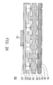
- FIG. 2A is a cross-sectional view of a keyboard module in FIG. 1 .
- FIG. 2B illustrates a decorative surface of a decorative sheet in FIG. 2A .
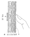
- FIG. 2C illustrates that the keyboard module in FIG. 2A is pressed by a finger.
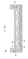
- FIG. 3 is a cross-sectional view of a keyboard module according to an embodiment of the present invention.
- FIG. 4 is a cross-sectional view of a keyboard module according to an embodiment of the present invention.
- FIG. 5 is a cross-sectional view of a keyboard module according to an embodiment of the present invention.
- FIG. 6A is a cross-sectional view of a keyboard module according to an embodiment of the present invention.
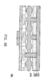
- FIG. 6B is a cross-sectional view of a keyboard module according to an embodiment of the present invention.
- FIG. 7 is a cross-sectional view of a keyboard module according to an embodiment of the present invention.
- FIG. 8A is a cross-sectional view of a keyboard module according to an embodiment of the present invention.
- FIG. 8B is a cross-sectional view of a keyboard module according to an embodiment of the present invention.
- FIG. 8C is a cross-sectional view of a keyboard module according to an embodiment of the present invention.
- FIG. 9A is a cross-sectional view of a keyboard module according to an embodiment of the present invention.
- FIG. 9B is a partial enlarged top view of the first elastic layer in FIG. 9A .
- FIG. 10 is a cross-sectional view of a keyboard module according to an embodiment of the present invention.
- FIG. 11A is a cross-sectional view of a keyboard module according to an embodiment of the present invention.
- FIG. 11B is a cross-sectional view of a keyboard module according to an embodiment of the present invention.
- FIG. 1 is a perspective view of an electronic apparatus according to an embodiment of the present invention.
- the electronic apparatus 10 may be an ultra mobile personal computer (UMPC).
- the electronic apparatus 10 includes a display unit 12 and a keyboard module 100, wherein the keyboard module 100 is electrically connected to the display unit 12.
- the keyboard module 100 and the display unit 12 are independent to each other.
- the keyboard module 100 and the display unit 12 may also be disposed on the same body.
- FIG. 2A is a cross-sectional view of the keyboard module in FIG. 1 .
- the keyboard module 100 includes a supporting structure 110, a membrane circuit sheet 120, and a vibrator 130.
- the supporting structure 110 has a carrying surface 112.
- the membrane circuit sheet 120 is disposed on the carrying surface 112 of the supporting structure 110 and has a plurality of triggers 122.
- the vibrator 130 is connected to the supporting structure 110 and disposed below the supporting structure 110.
- the vibrator 130 starts to vibrate to provide a tactile feedback in correspondence with the press of the user to the triggers 122.
- the triggers 122 usually include an upper electrical contact and a lower electrical contact (not shown), and when these triggers 122 are pressed by the user directly or indirectly and accordingly the two electrical contacts touch each other, signals are generated by these triggers 122 and transmitted to a central processing unit (CPU) or a microprocessor unit (MPU) in the electronic apparatus 10 (referring to FIG. 1 ) or a MPU in the keyboard module 100 (not shown).
- CPU central processing unit
- MPU microprocessor unit
- the CPU or MPU then drive the vibrator 130 to vibrate correspondingly so as to provide a tactile feedback in correspondence with the press of the user to the triggers 122.
- the vibrator 130 may vibrate vertically.
- the vibrator 130 may also vibrate horizontally or in other directions.
- the vibrator 130 may be a revolving vibrator or a linear vibrator.
- FIG. 2B illustrates the decorative surface of a decorative sheet in FIG. 2A .
- the keyboard module 100 may further include a decorative sheet 140, wherein the decorative sheet 140 is disposed on the membrane circuit sheet 120 and has a decorative surface 142.
- the decorative sheet 140 has a plurality of marks (for example, icons, symbols, characters, or numbers).
- the decorative sheet 140 may further have a plurality of protrusions 144, wherein the protrusions 144 are protruded from the decorative surface 142 and are respectively corresponding to the triggers 122.
- the marks are respectively located on the protrusions 144 so that when a user touches these protrusions 144 with a finger, the position of the finger can be obtained.
- the keyboard module 100 may further include a first elastic layer 150 disposed between the decorative sheet 140 and the membrane circuit sheet 120.
- the first elastic layer 150 has a plurality of protrusions 152 and a plurality of spacers 154, wherein the protrusions 152 are respectively corresponding to the triggers 122, and one of the spacers 154 is disposed between adjacent two of the protrusions 152.
- the first elastic layer 150 may be made of rubber.
- the thicknesses of the protrusions 152 and the spacers 154 are greater than the thicknesses of other portions of the first elastic layer 150.
- FIG. 2C illustrates that the keyboard module in FIG. 2A is pressed by a finger.
- the protrusion 152 is moved downward to press the membrane circuit sheet 120 so that the trigger 122 corresponding to the protrusion 144 is also pressed.
- the vibrator 130 connected to the supporting structure 110 starts to vibrate to provide a tactile feedback in correspondence with the press of the user to the trigger 122.
- the spacer 154 adjacent to the protrusion 152 reduces the deformations of other areas of the first elastic layer 150, so that inappropriate press to the trigger 122 corresponding to another protrusion 152 and accordingly the generation of unneeded signal can be avoided.
- FIG. 3 is a cross-sectional view of a keyboard module according to an embodiment of the present invention.
- the keyboard module 100A in FIG. 3 is similar to the keyboard module 100 in FIG. 2A , and the differences between the two are that the decorative sheet 140A and the first elastic layer 150A of the keyboard module 100A in FIG. 3 are formed integrally, and a plurality of vibrators 130A are connected to the supporting structure 110A and are located at one side of the membrane circuit sheet 120.
- FIG. 4 is a cross-sectional view of a keyboard module according to an embodiment of the present invention.
- the keyboard module 100B in FIG. 4 is similar to the keyboard module 100 in FIG. 2A , and the difference between the two is that the keyboard module 100B in FIG. 4 further includes a light source 160.
- the light source 160 is disposed at one side of the first elastic layer 150B and emits a light beam into the first elastic layer 150B, wherein the first elastic layer 150B is transparent and has a reflective surface 156 close to the first elastic layer 150B for reflecting the light beam to the decorative sheet 140B, so as to display the marks on the decorative surface 142B.
- the first elastic layer 150B may be made of transparent silicone, and the decorative surface 142B of the decorative sheet 140B is a plane.
- FIG. 5 is a cross-sectional view of a keyboard module according to an embodiment of the present invention.
- the keyboard module 100C in FIG. 5 is similar to the keyboard module 100 in FIG. 2A , and the difference between the two is that the keyboard module 100C in FIG. 5 further includes a light source 160 and a light guiding layer 170.
- the light guiding layer 170 is disposed between the decorative sheet 140B and the first elastic layer 150.
- the light source 160 is disposed at one side of the light guiding layer 170 for emitting a light beam to the light guiding layer 170, wherein the light guiding layer 170 guides the light beam to the decorative sheet 140B to display the marks (referring to FIG. 2B ) on the decorative surface 142B above the decorative sheet 140B.
- the decorative surface 142B of the decorative sheet 140B is a plane.
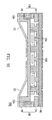
- FIG. 6A is a cross-sectional view of a keyboard module according to an embodiment of the present invention.
- the keyboard module 100D in FIG. 6A is similar to the keyboard module 100 in FIG. 2A , and the difference between the two is that the keyboard module 100D in FIG. 6A further includes a light emitting layer 180 disposed between the decorative sheet 140B and the first elastic layer 150.
- the decorative surface 142B of the decorative sheet 140B is a plane.
- the light emitting layer 180 emits a light beam to the decorative sheet 140B so as to display the marks (referring to FIG. 2B ) on the decorative surface 142B above the decorative sheet 140B.
- the light emitting layer 180 may be an electro-luminescence (EL) film or an organic electro-luminescence (OEL) film.
- FIG. 6B is a cross-sectional view of a keyboard module according to an embodiment of the present invention.
- the keyboard module 100E in FIG. 6B is similar to the keyboard module 100D in FIG. 6A , and the difference between the two is that the protrusions 152B of the first elastic layer 150B of the keyboard module 100E in FIG. 6B further pass through the light emitting layer 180A and are extended to the decorative sheet 140B.
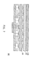
- FIG. 7 is a cross-sectional view of a keyboard module according to an embodiment of the present invention.
- the keyboard module 100F in FIG. 7 is similar to the keyboard module 100 in FIG. 2A , and the difference between the two is that the keyboard module 100F in FIG. 7 further includes a touch sensing panel 190 disposed between the decorative sheet 140B and the first elastic layer 150.
- the touch sensing panel 190 may be a capacitive touch panel or a resistive touch panel such that a user can input signals with a finger.
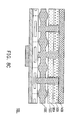
- FIG. 8A is a cross-sectional view of a keyboard module according to an embodiment of the present invention.
- the keyboard module 100G in FIG. 8A is similar to the keyboard module 100F in FIG. 7 , and the difference between the two is that the keyboard module 100G in FIG. 8A further includes a light emitting layer 180 disposed between the touch sensing panel 190 and the first elastic layer 150.
- FIG. 8B is a cross-sectional view of a keyboard module according to an embodiment of the present invention.
- the keyboard module 100H in FIG. 8B is similar to the keyboard module 100G in FIG. 8A , and the difference between the two is that the protrusions 152B of the first elastic layer 150B of the keyboard module 100H in FIG. 8B further pass through the light emitting layer 180A and are extended to the touch sensing panel 190.
- FIG. 8C is a cross-sectional view of a keyboard module according to an embodiment of the present invention.
- the keyboard module 100I in FIG. 8C is similar to the keyboard module 100H in FIG. 8B , and the difference between the two is that the protrusions 152C of the keyboard module 100I in FIG. 8C further pass through the light emitting layer 180A and the touch sensing panel 190A and are extended to the decorative sheet 140B.
- FIG. 9A is a cross-sectional view of a keyboard module according to an embodiment of the present invention
- FIG. 9B is a partial enlarged top view of the elastic layer in FIG. 9A
- the keyboard module 100J in FIG. 9A is similar to the keyboard module 100A in FIG. 3 , and the difference between the two is that the first elastic layer 150D of the keyboard module 100J in FIG. 9A further has a plurality of vibration conductors 158, and these vibration conductors 158 pass through the membrane circuit sheet 120A and are extended to the supporting structure 110A.
- both the first elastic layer 150D and the membrane circuit sheet 120A can absorb part of the vibration power of the vibrator 130A, in the keyboard module 100J of the present embodiment, the vibration conductors 158 are in contact with the supporting structure 110A so that the power consumption can be reduced and a user can sense the vibration obviously.
- each of the vibration conductors 158 is disposed between any adjacent four protrusions 152 for conducting the vibration.
- the protrusion 152 moves downward to press the membrane circuit sheet 120A so that a trigger 122 corresponding to the protrusion 144 is pressed.
- the vibrator 130A connected to the supporting structure 110A receives a corresponding electronic signal and starts to vibrate, and the vibration conductors 158 around the protrusions 152 conduct the vibration of the vibrator 130A to the decorative sheet 140C to provide a tactile feedback in correspondence with the press of the user to the trigger 122.
- most of the vibration power issued by the vibrator 130A is conducted to the decorative sheet 140C through the vibration conductors 158 and accordingly the vibration amplitude is increased.
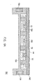
- FIG. 10 is a cross-sectional view of a keyboard module according to an embodiment of the present invention.
- the keyboard module 100K in FIG. 10 is similar to the keyboard module 100J in FIG. 9A , and the differences between the two are that the keyboard module 100K in FIG. 10 further includes a plurality of auxiliary vibration conductors 132, and the supporting structure 110B has an upper supporting structure 114 and a lower supporting structure 116.
- the auxiliary vibration conductors 132 span between a portion of the lower supporting structure 116 in contact with the vibrator 130A and another portion of the lower supporting structure 116 not in contact with the vibrator 130A.
- the upper supporting structure 114 is disposed between the decorative sheet 140C and a plurality of vibrators 130A
- the lower supporting structure 116 is disposed between a plurality of vibrators 130A and a plurality of auxiliary vibration conductors 132, wherein the auxiliary vibration conductors 132 are used for conducting the vibration of the vibrators 130A to the center of the lower supporting structure 116 or a part of the lower supporting structure 116 which receives less vibration, so that the decorative sheet 140C can provide approximately the same tactile feedback to the user at any position thereon.
- the auxiliary vibration conductors 132 and the lower supporting structure 116 may also be integrated into a single component.
- FIG. 11A is a cross-sectional view of a keyboard module according to an embodiment of the present invention.
- the keyboard module 100L in FIG. 11A is similar to the keyboard module 100A in FIG. 3 , and the difference between the two is that the second elastic layer 150E of the keyboard module 100L in FIG. 11A is disposed between the membrane circuit sheet 120 and the supporting structure 110A.
- the relative position between the second clastic layer 150E and the membrane circuit sheet 120 in FIG. 11A is contrary to the relative position between the first elastic layer 150A and the membrane circuit sheet 120 in FIG. 3 .
- FIG. 11B is a cross-sectional view of a keyboard module according to an embodiment of the present invention.
- the keyboard module 100M in FIG. 11B is similar to the keyboard module 100L in FIG. 11A , and the difference between the two is that the second elastic layer 150F of the keyboard module 100M in FIG. 11B further has a plurality of vibration conductors 158, wherein the vibration conductors 158 are extended to the decorative sheet 140C.
- the keyboard module has a vibrator such that when a user presses the membrane circuit sheet directly or indirectly, the vibrator vibrates the supporting structure and the membrane circuit sheet thereon so as to provide a tactile feedback in correspondence with the press of the user to the membrane circuit sheet.
- the tactile feedback in a conventional keyboard is simulated by using the vibrator, so as to indicate that the membrane circuit sheet has been pressed.
- the thickness of such a keyboard module which adopts the membrane circuit sheet can be reduced.
Landscapes
- Engineering & Computer Science (AREA)
- General Engineering & Computer Science (AREA)
- Theoretical Computer Science (AREA)
- Human Computer Interaction (AREA)
- Physics & Mathematics (AREA)
- General Physics & Mathematics (AREA)
- Input From Keyboards Or The Like (AREA)
- Push-Button Switches (AREA)
Abstract
Description
- The present invention generally relates to an electronic apparatus, in particular, to a keyboard module applied in an electronic apparatus.
- Along with the development of technologies, people rely more and more on electronic products. Various handheld electronic apparatuses, such as ultra mobile personal computer (UMPC), personal digital assistant (PDA), and mobile phone, have been developed to meet people's requirement for high-speed, high-performance, light, and slim electronic products.
- The keys on an existing keyboard (either a keyboard of a desktop computer or a keyboard of a notebook computer) usually require a large stroke. Accordingly, such a keyboard cannot be applied to a handheld electronic apparatus due to the limitation in the thickness of the handheld electronic apparatus. To be specific, the key structure in an existing keyboard applied in a handheld electronic apparatus includes a circuit board, a rubber layer, and a key, wherein the circuit board has at least one metal dome switch, and the rubber layer has a protrusion corresponding to the metal dome switch. A user can sense the tactile feedback provided by the metal dome switch when the user presses the key. However, a keyboard adopting such a key structure is usually very thick.
- Accordingly, the present application is directed to a keyboard module suitable for being applied to an electronic apparatus, wherein the keyboard module has a limited thickness.
- The present application is directed to an electronic apparatus having a keyboard module, wherein the keyboard module has a limited thickness.
- The present application provides a keyboard module suitable for being applied to an electronic apparatus. The keyboard module includes a supporting structure, a membrane circuit sheet, and a vibrator. The supporting structure has a carrying surface. The membrane circuit sheet is disposed on the carrying surface of the supporting structure and has a plurality of triggers. The vibrator is connected to the supporting structure.
- The present application provides an electronic apparatus including a display unit and the keyboard module as described above. The keyboard module is electrically connected to the display unit.
- As described above, when a user presses the membrane circuit sheet directly or indirectly, the vibrator vibrates the supporting structure and the membrane circuit sheet disposed thereon to provide a tactile feedback in correspondence with the press of the user to the membrane circuit sheet. In addition, the thickness of the keyboard module which adopts foregoing membrane circuit sheet is reduced.
- The accompanying drawings are included to provide a further understanding of the invention, and are incorporated in and constitute a part of this specification. The drawings illustrate embodiments of the invention and, together with the description, serve to explain the principles of the invention.
-
FIG. 1 is a perspective view of an electronic apparatus according to an embodiment of the present invention. -
FIG. 2A is a cross-sectional view of a keyboard module inFIG. 1 . -
FIG. 2B illustrates a decorative surface of a decorative sheet inFIG. 2A . -
FIG. 2C illustrates that the keyboard module inFIG. 2A is pressed by a finger. -
FIG. 3 is a cross-sectional view of a keyboard module according to an embodiment of the present invention. -
FIG. 4 is a cross-sectional view of a keyboard module according to an embodiment of the present invention. -
FIG. 5 is a cross-sectional view of a keyboard module according to an embodiment of the present invention. -
FIG. 6A is a cross-sectional view of a keyboard module according to an embodiment of the present invention. -
FIG. 6B is a cross-sectional view of a keyboard module according to an embodiment of the present invention. -
FIG. 7 is a cross-sectional view of a keyboard module according to an embodiment of the present invention. -
FIG. 8A is a cross-sectional view of a keyboard module according to an embodiment of the present invention. -
FIG. 8B is a cross-sectional view of a keyboard module according to an embodiment of the present invention. -
FIG. 8C is a cross-sectional view of a keyboard module according to an embodiment of the present invention. -
FIG. 9A is a cross-sectional view of a keyboard module according to an embodiment of the present invention. -
FIG. 9B is a partial enlarged top view of the first elastic layer inFIG. 9A . -
FIG. 10 is a cross-sectional view of a keyboard module according to an embodiment of the present invention. -
FIG. 11A is a cross-sectional view of a keyboard module according to an embodiment of the present invention. -
FIG. 11B is a cross-sectional view of a keyboard module according to an embodiment of the present invention. - Reference will now be made in detail to the present embodiments of the invention, examples of which are illustrated in the accompanying drawings. Wherever possible, the same reference numbers are used in the drawings and the description to refer to the same or like parts.
-
FIG. 1 is a perspective view of an electronic apparatus according to an embodiment of the present invention. Referring toFIG. 1 , in the present embodiment, theelectronic apparatus 10 may be an ultra mobile personal computer (UMPC). Theelectronic apparatus 10 includes adisplay unit 12 and akeyboard module 100, wherein thekeyboard module 100 is electrically connected to thedisplay unit 12. In the present embodiment, thekeyboard module 100 and thedisplay unit 12 are independent to each other. However, in another embodiment of the present invention, thekeyboard module 100 and thedisplay unit 12 may also be disposed on the same body. -
FIG. 2A is a cross-sectional view of the keyboard module inFIG. 1 . Referring toFIG. 2A , in the present embodiment, thekeyboard module 100 includes a supportingstructure 110, amembrane circuit sheet 120, and avibrator 130. The supportingstructure 110 has a carryingsurface 112. Themembrane circuit sheet 120 is disposed on the carryingsurface 112 of the supportingstructure 110 and has a plurality oftriggers 122. Thevibrator 130 is connected to the supportingstructure 110 and disposed below the supportingstructure 110. - When these
triggers 122 are pressed by a user directly or indirectly, thevibrator 130 starts to vibrate to provide a tactile feedback in correspondence with the press of the user to thetriggers 122. To be specific, thetriggers 122 usually include an upper electrical contact and a lower electrical contact (not shown), and when thesetriggers 122 are pressed by the user directly or indirectly and accordingly the two electrical contacts touch each other, signals are generated by thesetriggers 122 and transmitted to a central processing unit (CPU) or a microprocessor unit (MPU) in the electronic apparatus 10 (referring toFIG. 1 ) or a MPU in the keyboard module 100 (not shown). The CPU or MPU then drive thevibrator 130 to vibrate correspondingly so as to provide a tactile feedback in correspondence with the press of the user to thetriggers 122. In the present embodiment, thevibrator 130 may vibrate vertically. However, thevibrator 130 may also vibrate horizontally or in other directions. In addition, thevibrator 130 may be a revolving vibrator or a linear vibrator. -
FIG. 2B illustrates the decorative surface of a decorative sheet inFIG. 2A . Referring toFIG. 2A andFIG. 2B , thekeyboard module 100 may further include adecorative sheet 140, wherein thedecorative sheet 140 is disposed on themembrane circuit sheet 120 and has adecorative surface 142. In the present embodiment, thedecorative sheet 140 has a plurality of marks (for example, icons, symbols, characters, or numbers). Besides, thedecorative sheet 140 may further have a plurality ofprotrusions 144, wherein theprotrusions 144 are protruded from thedecorative surface 142 and are respectively corresponding to thetriggers 122. The marks are respectively located on theprotrusions 144 so that when a user touches theseprotrusions 144 with a finger, the position of the finger can be obtained. - Referring to
FIG. 2A , thekeyboard module 100 may further include a firstelastic layer 150 disposed between thedecorative sheet 140 and themembrane circuit sheet 120. The firstelastic layer 150 has a plurality ofprotrusions 152 and a plurality ofspacers 154, wherein theprotrusions 152 are respectively corresponding to thetriggers 122, and one of thespacers 154 is disposed between adjacent two of theprotrusions 152. In the present embodiment, the firstelastic layer 150 may be made of rubber. Besides, the thicknesses of theprotrusions 152 and thespacers 154 are greater than the thicknesses of other portions of the firstelastic layer 150. -
FIG. 2C illustrates that the keyboard module inFIG. 2A is pressed by a finger. Referring toFIG. 2C , when a user presses aprotrusion 144 on thedecorative sheet 140 with a finger, theprotrusion 152 is moved downward to press themembrane circuit sheet 120 so that thetrigger 122 corresponding to theprotrusion 144 is also pressed. Accordingly, thevibrator 130 connected to the supportingstructure 110 starts to vibrate to provide a tactile feedback in correspondence with the press of the user to thetrigger 122. - It should be noted that when the
protrusion 152 is pressed by an external force and accordingly presses themembrane circuit sheet 120, thespacer 154 adjacent to theprotrusion 152 reduces the deformations of other areas of the firstelastic layer 150, so that inappropriate press to thetrigger 122 corresponding to anotherprotrusion 152 and accordingly the generation of unneeded signal can be avoided. -
FIG. 3 is a cross-sectional view of a keyboard module according to an embodiment of the present invention. Referring to bothFIG. 2A andFIG. 3 , thekeyboard module 100A inFIG. 3 is similar to thekeyboard module 100 inFIG. 2A , and the differences between the two are that thedecorative sheet 140A and the firstelastic layer 150A of thekeyboard module 100A inFIG. 3 are formed integrally, and a plurality ofvibrators 130A are connected to the supportingstructure 110A and are located at one side of themembrane circuit sheet 120. -
FIG. 4 is a cross-sectional view of a keyboard module according to an embodiment of the present invention. Referring toFIG. 2A andFIG. 4 , thekeyboard module 100B inFIG. 4 is similar to thekeyboard module 100 inFIG. 2A , and the difference between the two is that thekeyboard module 100B inFIG. 4 further includes alight source 160. Thelight source 160 is disposed at one side of the firstelastic layer 150B and emits a light beam into the firstelastic layer 150B, wherein the firstelastic layer 150B is transparent and has areflective surface 156 close to the firstelastic layer 150B for reflecting the light beam to thedecorative sheet 140B, so as to display the marks on thedecorative surface 142B. In the present embodiment, the firstelastic layer 150B may be made of transparent silicone, and thedecorative surface 142B of thedecorative sheet 140B is a plane. -
FIG. 5 is a cross-sectional view of a keyboard module according to an embodiment of the present invention. Referring to bothFIG. 2A andFIG. 5 , thekeyboard module 100C inFIG. 5 is similar to thekeyboard module 100 inFIG. 2A , and the difference between the two is that thekeyboard module 100C inFIG. 5 further includes alight source 160 and alight guiding layer 170. Thelight guiding layer 170 is disposed between thedecorative sheet 140B and the firstelastic layer 150. Thelight source 160 is disposed at one side of thelight guiding layer 170 for emitting a light beam to thelight guiding layer 170, wherein thelight guiding layer 170 guides the light beam to thedecorative sheet 140B to display the marks (referring toFIG. 2B ) on thedecorative surface 142B above thedecorative sheet 140B. Besides, thedecorative surface 142B of thedecorative sheet 140B is a plane. -
FIG. 6A is a cross-sectional view of a keyboard module according to an embodiment of the present invention. Referring to bothFIG. 2A andFIG. 6A , thekeyboard module 100D inFIG. 6A is similar to thekeyboard module 100 inFIG. 2A , and the difference between the two is that thekeyboard module 100D inFIG. 6A further includes alight emitting layer 180 disposed between thedecorative sheet 140B and the firstelastic layer 150. Besides, thedecorative surface 142B of thedecorative sheet 140B is a plane. Thelight emitting layer 180 emits a light beam to thedecorative sheet 140B so as to display the marks (referring toFIG. 2B ) on thedecorative surface 142B above thedecorative sheet 140B. In the present embodiment, thelight emitting layer 180 may be an electro-luminescence (EL) film or an organic electro-luminescence (OEL) film. -
FIG. 6B is a cross-sectional view of a keyboard module according to an embodiment of the present invention. Referring to bothFIG. 6A andFIG. 6B , thekeyboard module 100E inFIG. 6B is similar to thekeyboard module 100D inFIG. 6A , and the difference between the two is that theprotrusions 152B of the firstelastic layer 150B of thekeyboard module 100E inFIG. 6B further pass through thelight emitting layer 180A and are extended to thedecorative sheet 140B. -
FIG. 7 is a cross-sectional view of a keyboard module according to an embodiment of the present invention. Referring toFIG. 2A andFIG. 7 , thekeyboard module 100F inFIG. 7 is similar to thekeyboard module 100 inFIG. 2A , and the difference between the two is that thekeyboard module 100F inFIG. 7 further includes atouch sensing panel 190 disposed between thedecorative sheet 140B and the firstelastic layer 150. In the present embodiment, thetouch sensing panel 190 may be a capacitive touch panel or a resistive touch panel such that a user can input signals with a finger. -
FIG. 8A is a cross-sectional view of a keyboard module according to an embodiment of the present invention. Referring toFIG. 7 andFIG. 8A , thekeyboard module 100G inFIG. 8A is similar to thekeyboard module 100F inFIG. 7 , and the difference between the two is that thekeyboard module 100G inFIG. 8A further includes alight emitting layer 180 disposed between thetouch sensing panel 190 and the firstelastic layer 150. -
FIG. 8B is a cross-sectional view of a keyboard module according to an embodiment of the present invention. Referring toFIG. 8A andFIG. 8B , thekeyboard module 100H inFIG. 8B is similar to thekeyboard module 100G inFIG. 8A , and the difference between the two is that theprotrusions 152B of the firstelastic layer 150B of thekeyboard module 100H inFIG. 8B further pass through thelight emitting layer 180A and are extended to thetouch sensing panel 190. -
FIG. 8C is a cross-sectional view of a keyboard module according to an embodiment of the present invention. Referring toFIG. 8B andFIG. 8C , the keyboard module 100I inFIG. 8C is similar to thekeyboard module 100H inFIG. 8B , and the difference between the two is that theprotrusions 152C of the keyboard module 100I inFIG. 8C further pass through thelight emitting layer 180A and thetouch sensing panel 190A and are extended to thedecorative sheet 140B. -
FIG. 9A is a cross-sectional view of a keyboard module according to an embodiment of the present invention, andFIG. 9B is a partial enlarged top view of the elastic layer inFIG. 9A . Referring toFIG. 3 ,FIG. 9A , andFIG. 9B , thekeyboard module 100J inFIG. 9A is similar to thekeyboard module 100A inFIG. 3 , and the difference between the two is that the firstelastic layer 150D of thekeyboard module 100J inFIG. 9A further has a plurality ofvibration conductors 158, and thesevibration conductors 158 pass through themembrane circuit sheet 120A and are extended to the supportingstructure 110A. Because both the firstelastic layer 150D and themembrane circuit sheet 120A can absorb part of the vibration power of thevibrator 130A, in thekeyboard module 100J of the present embodiment, thevibration conductors 158 are in contact with the supportingstructure 110A so that the power consumption can be reduced and a user can sense the vibration obviously. - To be specific, in the present embodiment, each of the
vibration conductors 158 is disposed between any adjacent fourprotrusions 152 for conducting the vibration. In other words, when a user press aprotrusion 144 on thedecorative sheet 140C with a finger, theprotrusion 152 moves downward to press themembrane circuit sheet 120A so that atrigger 122 corresponding to theprotrusion 144 is pressed. Then, thevibrator 130A connected to the supportingstructure 110A receives a corresponding electronic signal and starts to vibrate, and thevibration conductors 158 around theprotrusions 152 conduct the vibration of thevibrator 130A to thedecorative sheet 140C to provide a tactile feedback in correspondence with the press of the user to thetrigger 122. Thus, most of the vibration power issued by thevibrator 130A is conducted to thedecorative sheet 140C through thevibration conductors 158 and accordingly the vibration amplitude is increased. -
FIG. 10 is a cross-sectional view of a keyboard module according to an embodiment of the present invention. Referring toFIG. 10 andFIG. 9A , thekeyboard module 100K inFIG. 10 is similar to thekeyboard module 100J inFIG. 9A , and the differences between the two are that thekeyboard module 100K inFIG. 10 further includes a plurality ofauxiliary vibration conductors 132, and the supportingstructure 110B has an upper supportingstructure 114 and a lower supportingstructure 116. Theauxiliary vibration conductors 132 span between a portion of the lower supportingstructure 116 in contact with thevibrator 130A and another portion of the lower supportingstructure 116 not in contact with thevibrator 130A. - To be specific, the
upper supporting structure 114 is disposed between thedecorative sheet 140C and a plurality ofvibrators 130A, and the lower supportingstructure 116 is disposed between a plurality ofvibrators 130A and a plurality ofauxiliary vibration conductors 132, wherein theauxiliary vibration conductors 132 are used for conducting the vibration of thevibrators 130A to the center of the lower supportingstructure 116 or a part of the lower supportingstructure 116 which receives less vibration, so that thedecorative sheet 140C can provide approximately the same tactile feedback to the user at any position thereon. Besides, theauxiliary vibration conductors 132 and the lower supportingstructure 116 may also be integrated into a single component. -
FIG. 11A is a cross-sectional view of a keyboard module according to an embodiment of the present invention. Referring toFIG. 3 andFIG. 11A , thekeyboard module 100L inFIG. 11A is similar to thekeyboard module 100A inFIG. 3 , and the difference between the two is that the secondelastic layer 150E of thekeyboard module 100L inFIG. 11A is disposed between themembrane circuit sheet 120 and the supportingstructure 110A. In short, the relative position between the secondclastic layer 150E and themembrane circuit sheet 120 inFIG. 11A is contrary to the relative position between the firstelastic layer 150A and themembrane circuit sheet 120 inFIG. 3 . -
FIG. 11B is a cross-sectional view of a keyboard module according to an embodiment of the present invention. Referring toFIG. 11A andFIG. 11B , thekeyboard module 100M inFIG. 11B is similar to thekeyboard module 100L inFIG. 11A , and the difference between the two is that the second elastic layer 150F of thekeyboard module 100M inFIG. 11B further has a plurality ofvibration conductors 158, wherein thevibration conductors 158 are extended to thedecorative sheet 140C. - In overview, the keyboard module has a vibrator such that when a user presses the membrane circuit sheet directly or indirectly, the vibrator vibrates the supporting structure and the membrane circuit sheet thereon so as to provide a tactile feedback in correspondence with the press of the user to the membrane circuit sheet. Thereby, the tactile feedback in a conventional keyboard is simulated by using the vibrator, so as to indicate that the membrane circuit sheet has been pressed. Moreover, the thickness of such a keyboard module which adopts the membrane circuit sheet can be reduced.
- It will be apparent to those skilled in the art that various modifications and variations can be made to the structure of the present invention without departing from the scope or spirit of the invention. In view of the foregoing, it is intended that the present invention cover modifications and variations of this invention provided they fall within the scope of the following claims and their equivalents.
Claims (15)
- A keyboard module, suitable for being applied to an electronic apparatus, the keyboard module comprising:a supporting structure, having a carrying surface;a membrane circuit sheet, disposed on the carrying surface of the supporting structure, the membrane circuit sheet having a plurality of triggers; anda vibrator, connected to the supporting structure.
- The keyboard module according to claim 1 further comprising:a decorative sheet, disposed on the membrane circuit sheet, the decorative sheet having a decorative surface.
- The keyboard module according to claim 2, wherein the decorative sheet is a plane and has a plurality of marks on the decorative surface, and the marks are respectively corresponding to the triggers.
- The keyboard module according to claim 2, wherein the decorative sheet has a plurality of protrusions and a plurality of marks, the protrusions are protruded from the decorative surface and are respectively corresponding to the triggers, and the marks are respectively located on the protrusions.
- The keyboard module according to claim 2 further comprising:a first elastic layer, disposed between the decorative sheet and the membrane circuit sheet, wherein the first elastic layer has a plurality of protrusions and a plurality of spacers, the protrusions are respectively corresponding to the triggers, and one of the spacers is disposed between adjacent two of the protrusions.
- The keyboard module according to claim 5, wherein the decorative sheet and the first elastic layer are formed integrally.
- The keyboard module according to claim 5, wherein the protrusions are extended to the decorative sheet.
- The keyboard module according to claim 5 further comprising:a touch sensing panel, disposed between the decorative sheet and the first elastic layer.
- The keyboard module according to claim 8, wherein the protrusions are extended to the touch sensing panel.
- The keyboard module according to claim 5, wherein the first elastic layer has a plurality of vibration conductors, and the vibration conductors pass through the membrane circuit sheet and are extended to the supporting structure.
- The keyboard module according to claim 10 further comprising:an auxiliary vibration conductor, spanning between a portion of the supporting structure in contact with the vibrator and another portion of the supporting structure not in contact with the vibrator.
- The keyboard module according to claim 11, wherein the supporting structure has an upper supporting structure and a lower supporting structure, the upper supporting structure is disposed between the decorative sheet and the vibrator, and the lower supporting structure is disposed between the vibrator and the auxiliary vibration conductor.
- The keyboard module according to claim 2 further comprising:a second elastic layer, disposed between the membrane circuit sheet and the supporting structure, wherein the second elastic layer has a plurality of protrusions and a plurality of spacers, the protrusions are respectively corresponding to the triggers, and one of the spacers is disposed between adjacent two of the protrusions.
- The keyboard module according to claim 13, wherein the second elastic layer has a plurality of vibration conductors extended to the decorative sheet.
- An electronic apparatus, comprising:a display unit; anda keyboard module of claim 1, electrically connected to the display unit.
Applications Claiming Priority (2)
| Application Number | Priority Date | Filing Date | Title |
|---|---|---|---|
| TW96150583 | 2007-12-27 | ||
| TW097108882A TWI356433B (en) | 2007-12-27 | 2008-03-13 | Keyboard module and electronic apparatus |
Publications (2)
| Publication Number | Publication Date |
|---|---|
| EP2075673A1 true EP2075673A1 (en) | 2009-07-01 |
| EP2075673B1 EP2075673B1 (en) | 2011-09-28 |
Family
ID=40427108
Family Applications (1)
| Application Number | Title | Priority Date | Filing Date |
|---|---|---|---|
| EP08019183A Active EP2075673B1 (en) | 2007-12-27 | 2008-11-03 | Keyboard module and electronic apparatus |
Country Status (3)
| Country | Link |
|---|---|
| US (1) | US8477100B2 (en) |
| EP (1) | EP2075673B1 (en) |
| TW (1) | TWI356433B (en) |
Families Citing this family (17)
| Publication number | Priority date | Publication date | Assignee | Title |
|---|---|---|---|---|
| US8648810B2 (en) * | 2011-02-14 | 2014-02-11 | Ko Ja (Cayman) Co., Ltd. | Integrated input apparatus |
| USD665805S1 (en) * | 2011-09-12 | 2012-08-21 | Minebea Co., Ltd. | Flat keyboard with character symbols |
| CN103947113B (en) * | 2011-09-22 | 2016-12-21 | 贝洱海拉温控系统有限公司 | Operation device |
| TWI524218B (en) | 2011-10-05 | 2016-03-01 | 廣達電腦股份有限公司 | Method and electronic device for virtual keyboard with haptic feedback |
| US9064654B2 (en) | 2012-03-02 | 2015-06-23 | Microsoft Technology Licensing, Llc | Method of manufacturing an input device |
| US9870066B2 (en) * | 2012-03-02 | 2018-01-16 | Microsoft Technology Licensing, Llc | Method of manufacturing an input device |
| US9134807B2 (en) | 2012-03-02 | 2015-09-15 | Microsoft Technology Licensing, Llc | Pressure sensitive key normalization |
| US9075566B2 (en) | 2012-03-02 | 2015-07-07 | Microsoft Technoogy Licensing, LLC | Flexible hinge spine |
| US9706089B2 (en) | 2012-03-02 | 2017-07-11 | Microsoft Technology Licensing, Llc | Shifted lens camera for mobile computing devices |
| US20130300590A1 (en) | 2012-05-14 | 2013-11-14 | Paul Henry Dietz | Audio Feedback |
| US10031556B2 (en) | 2012-06-08 | 2018-07-24 | Microsoft Technology Licensing, Llc | User experience adaptation |
| US20140062683A1 (en) * | 2012-09-05 | 2014-03-06 | Nzxt Corporation | Body sensing computer keyboard |
| WO2014059618A1 (en) | 2012-10-17 | 2014-04-24 | Microsoft Corporation | Graphic formation via material ablation |
| US9728352B2 (en) | 2014-01-13 | 2017-08-08 | Htc Corporation | Switch structure and electronic device using the same |
| CN107943304B (en) * | 2017-10-26 | 2020-07-10 | 捷开通讯(深圳)有限公司 | Keyboard and intelligent mobile terminal provided with same |
| KR102130776B1 (en) * | 2018-05-16 | 2020-07-08 | 주식회사 닷 | Information output apparatus |
| TWI875580B (en) * | 2024-04-29 | 2025-03-01 | 矽統科技股份有限公司 | Touchpad and keyboard integrated device |
Citations (7)
| Publication number | Priority date | Publication date | Assignee | Title |
|---|---|---|---|---|
| US20040207542A1 (en) * | 2003-04-16 | 2004-10-21 | Massachusetts Institute Of Technology | Methods and apparatus for vibrotactile communication |
| WO2005081275A1 (en) * | 2004-02-20 | 2005-09-01 | Pelikon Limited | Switches |
| US20050259081A1 (en) * | 2004-05-24 | 2005-11-24 | Alps Electric Co., Ltd. | Input device |
| EP1699065A2 (en) * | 2000-05-22 | 2006-09-06 | Digit Wireless, Llc | Input devices and their use |
| US20060204303A1 (en) * | 2005-03-14 | 2006-09-14 | Michael Yurochko | Stack assembly for implementing keypads on mobile computing devices |
| DE202006011302U1 (en) * | 2006-07-22 | 2006-09-21 | Hoffmann & Krippner Gmbh | Keyboard, has evaluation unit freely programmed based on allocation of determined depressing positions and switching threshold e.g. minimum depressing force, for successive key operation and programmed at depressing positions for user |
| EP1722292A2 (en) * | 2005-05-09 | 2006-11-15 | Hosiden Corporation | El-illuminated switch |
Family Cites Families (17)
| Publication number | Priority date | Publication date | Assignee | Title |
|---|---|---|---|---|
| US4532395A (en) * | 1983-09-20 | 1985-07-30 | Timex Corporation | Electroluminescent flexible touch switch panel |
| JPH01243325A (en) | 1988-03-25 | 1989-09-28 | Matsushita Electric Ind Co Ltd | Input device |
| CA2048458C (en) * | 1990-08-07 | 1995-02-14 | Hisamitsu Takagi | Portable telephone set |
| US5053585A (en) * | 1990-10-12 | 1991-10-01 | Interlink Electronics, Incorporated | Multipurpose keyboard using digitizer pad featuring spatial minimization of a pressure contact area and method of making same |
| US5180237A (en) * | 1992-06-23 | 1993-01-19 | Getac Corporation | Keyboard for under water use |
| US6218966B1 (en) | 1998-11-05 | 2001-04-17 | International Business Machines Corporation | Tactile feedback keyboard |
| US6139362A (en) * | 1999-07-30 | 2000-10-31 | Berg Technology, Inc. | Fastener for connecting an electrical device to a substrate |
| US6693626B1 (en) | 1999-12-07 | 2004-02-17 | Immersion Corporation | Haptic feedback using a keyboard device |
| DE20102197U1 (en) | 2001-02-08 | 2001-06-13 | Kim Han Sung | Touchscreen with a touch input that confirms the user |
| KR100384993B1 (en) | 2001-05-22 | 2003-05-23 | 주식회사 유일전자 | One body type keypad for having electro luminescent lamp |
| US7352356B2 (en) | 2001-12-13 | 2008-04-01 | United States Of America | Refreshable scanning tactile graphic display for localized sensory stimulation |
| TWI229357B (en) | 2004-05-31 | 2005-03-11 | Wistron Corp | Electronic device and keyboard thereof |
| US7525534B2 (en) * | 2005-03-14 | 2009-04-28 | Palm, Inc. | Small form-factor keypad for mobile computing devices |
| TWI264931B (en) * | 2005-04-29 | 2006-10-21 | Benq Corp | Keytop module for cellular phones |
| TWI269331B (en) | 2005-06-02 | 2006-12-21 | Behavior Tech Computer Corp | Light pervious keyboard switch structure and light pervious keyboard made thereof |
| TWM311082U (en) | 2006-09-08 | 2007-05-01 | Ichia Tech Inc | Light-pervious sense-touching keyboard |
| CN200990323Y (en) | 2006-09-19 | 2007-12-12 | 毅嘉科技股份有限公司 | Translucent touch-sensitive keyboard |
-
2008
- 2008-03-13 TW TW097108882A patent/TWI356433B/en active
- 2008-10-30 US US12/261,063 patent/US8477100B2/en active Active
- 2008-11-03 EP EP08019183A patent/EP2075673B1/en active Active
Patent Citations (7)
| Publication number | Priority date | Publication date | Assignee | Title |
|---|---|---|---|---|
| EP1699065A2 (en) * | 2000-05-22 | 2006-09-06 | Digit Wireless, Llc | Input devices and their use |
| US20040207542A1 (en) * | 2003-04-16 | 2004-10-21 | Massachusetts Institute Of Technology | Methods and apparatus for vibrotactile communication |
| WO2005081275A1 (en) * | 2004-02-20 | 2005-09-01 | Pelikon Limited | Switches |
| US20050259081A1 (en) * | 2004-05-24 | 2005-11-24 | Alps Electric Co., Ltd. | Input device |
| US20060204303A1 (en) * | 2005-03-14 | 2006-09-14 | Michael Yurochko | Stack assembly for implementing keypads on mobile computing devices |
| EP1722292A2 (en) * | 2005-05-09 | 2006-11-15 | Hosiden Corporation | El-illuminated switch |
| DE202006011302U1 (en) * | 2006-07-22 | 2006-09-21 | Hoffmann & Krippner Gmbh | Keyboard, has evaluation unit freely programmed based on allocation of determined depressing positions and switching threshold e.g. minimum depressing force, for successive key operation and programmed at depressing positions for user |
Also Published As
| Publication number | Publication date |
|---|---|
| TW200928876A (en) | 2009-07-01 |
| US8477100B2 (en) | 2013-07-02 |
| US20090167690A1 (en) | 2009-07-02 |
| TWI356433B (en) | 2012-01-11 |
| EP2075673B1 (en) | 2011-09-28 |
Similar Documents
| Publication | Publication Date | Title |
|---|---|---|
| EP2075673B1 (en) | Keyboard module and electronic apparatus | |
| US9299515B2 (en) | Luminous keyboard | |
| US9230753B2 (en) | Illuminated touch keyboard | |
| US7915556B2 (en) | Input panel and portable electronic device using the same | |
| US9423836B2 (en) | Super-slim touch keyboard and super-slim cover device for smart keyboard having the same | |
| US20080135392A1 (en) | Illuminating Membrane Switch and Illuminating Keypad Using the Same | |
| US20100321298A1 (en) | Keyboard and touchpad combination | |
| US20140138227A1 (en) | Illuminated keyboard | |
| US9142370B2 (en) | Illuminated keyboard | |
| TWI498773B (en) | Luminous keyboard | |
| US9384918B2 (en) | Illuminated keyboard | |
| US20180330899A1 (en) | Keyboard device | |
| CN101587789B (en) | Key module | |
| CN101477911A (en) | Keyboard module and electronic device | |
| US9685286B2 (en) | Keyboard device | |
| KR101474964B1 (en) | Super slim touch keyboard | |
| CN102947775B (en) | Dynamic display keyboard and the key be used in dynamic display keyboard | |
| US20110073449A1 (en) | Keyboard | |
| CN114242500A (en) | Keyboard and electronic equipment that can give out light | |
| US20210327661A1 (en) | Keyboard having touch-sensitive keycaps which are also pressable and method for making same | |
| TWI836653B (en) | Keyboard device | |
| CN201698336U (en) | Key module with organic light-emitting display panel and portable electronic device | |
| JP7751058B1 (en) | Keyboard device and information equipment system | |
| US20230129207A1 (en) | Key structure | |
| EP4711900A1 (en) | Keyboard device and information apparatus system |
Legal Events
| Date | Code | Title | Description |
|---|---|---|---|
| PUAI | Public reference made under article 153(3) epc to a published international application that has entered the european phase |
Free format text: ORIGINAL CODE: 0009012 |
|
| 17P | Request for examination filed |
Effective date: 20081103 |
|
| AK | Designated contracting states |
Kind code of ref document: A1 Designated state(s): AT BE BG CH CY CZ DE DK EE ES FI FR GB GR HR HU IE IS IT LI LT LU LV MC MT NL NO PL PT RO SE SI SK TR |
|
| AX | Request for extension of the european patent |
Extension state: AL BA MK RS |
|
| 17Q | First examination report despatched |
Effective date: 20090819 |
|
| AKX | Designation fees paid |
Designated state(s): DE FR GB NL |
|
| GRAP | Despatch of communication of intention to grant a patent |
Free format text: ORIGINAL CODE: EPIDOSNIGR1 |
|
| GRAS | Grant fee paid |
Free format text: ORIGINAL CODE: EPIDOSNIGR3 |
|
| GRAA | (expected) grant |
Free format text: ORIGINAL CODE: 0009210 |
|
| AK | Designated contracting states |
Kind code of ref document: B1 Designated state(s): DE FR GB NL |
|
| REG | Reference to a national code |
Ref country code: GB Ref legal event code: FG4D |
|
| REG | Reference to a national code |
Ref country code: DE Ref legal event code: R096 Ref document number: 602008010090 Country of ref document: DE Effective date: 20111201 |
|
| REG | Reference to a national code |
Ref country code: NL Ref legal event code: T3 |
|
| PLBE | No opposition filed within time limit |
Free format text: ORIGINAL CODE: 0009261 |
|
| STAA | Information on the status of an ep patent application or granted ep patent |
Free format text: STATUS: NO OPPOSITION FILED WITHIN TIME LIMIT |
|
| 26N | No opposition filed |
Effective date: 20120629 |
|
| REG | Reference to a national code |
Ref country code: DE Ref legal event code: R097 Ref document number: 602008010090 Country of ref document: DE Effective date: 20120629 |
|
| REG | Reference to a national code |
Ref country code: FR Ref legal event code: PLFP Year of fee payment: 8 |
|
| REG | Reference to a national code |
Ref country code: FR Ref legal event code: PLFP Year of fee payment: 9 |
|
| REG | Reference to a national code |
Ref country code: FR Ref legal event code: PLFP Year of fee payment: 10 |
|
| REG | Reference to a national code |
Ref country code: FR Ref legal event code: PLFP Year of fee payment: 11 |
|
| P01 | Opt-out of the competence of the unified patent court (upc) registered |
Effective date: 20230602 |
|
| PGFP | Annual fee paid to national office [announced via postgrant information from national office to epo] |
Ref country code: NL Payment date: 20250912 Year of fee payment: 18 |
|
| PGFP | Annual fee paid to national office [announced via postgrant information from national office to epo] |
Ref country code: GB Payment date: 20250911 Year of fee payment: 18 |
|
| PGFP | Annual fee paid to national office [announced via postgrant information from national office to epo] |
Ref country code: FR Payment date: 20250908 Year of fee payment: 18 |
|
| PGFP | Annual fee paid to national office [announced via postgrant information from national office to epo] |
Ref country code: DE Payment date: 20250910 Year of fee payment: 18 |