EP2075606A1 - Cable installation using induction - Google Patents
Cable installation using induction Download PDFInfo
- Publication number
- EP2075606A1 EP2075606A1 EP07255067A EP07255067A EP2075606A1 EP 2075606 A1 EP2075606 A1 EP 2075606A1 EP 07255067 A EP07255067 A EP 07255067A EP 07255067 A EP07255067 A EP 07255067A EP 2075606 A1 EP2075606 A1 EP 2075606A1
- Authority
- EP
- European Patent Office
- Prior art keywords
- conduit
- air
- conduit end
- detector
- cable
- Prior art date
- Legal status (The legal status is an assumption and is not a legal conclusion. Google has not performed a legal analysis and makes no representation as to the accuracy of the status listed.)
- Ceased
Links
Images


Classifications
-
- H—ELECTRICITY
- H02—GENERATION; CONVERSION OR DISTRIBUTION OF ELECTRIC POWER
- H02G—INSTALLATION OF ELECTRIC CABLES OR LINES, OR OF COMBINED OPTICAL AND ELECTRIC CABLES OR LINES
- H02G1/00—Methods or apparatus specially adapted for installing, maintaining, repairing or dismantling electric cables or lines
- H02G1/06—Methods or apparatus specially adapted for installing, maintaining, repairing or dismantling electric cables or lines for laying cables, e.g. laying apparatus on vehicle
- H02G1/08—Methods or apparatus specially adapted for installing, maintaining, repairing or dismantling electric cables or lines for laying cables, e.g. laying apparatus on vehicle through tubing or conduit, e.g. rod or draw wire for pushing or pulling
- H02G1/086—Methods or apparatus specially adapted for installing, maintaining, repairing or dismantling electric cables or lines for laying cables, e.g. laying apparatus on vehicle through tubing or conduit, e.g. rod or draw wire for pushing or pulling using fluid as pulling means, e.g. liquid, pressurised gas or suction means
-
- G—PHYSICS
- G01—MEASURING; TESTING
- G01P—MEASURING LINEAR OR ANGULAR SPEED, ACCELERATION, DECELERATION, OR SHOCK; INDICATING PRESENCE, ABSENCE, OR DIRECTION, OF MOVEMENT
- G01P13/00—Indicating or recording presence, absence, or direction, of movement
- G01P13/0006—Indicating or recording presence, absence, or direction, of movement of fluids or of granulous or powder-like substances
- G01P13/0013—Indicating or recording presence, absence, or direction, of movement of fluids or of granulous or powder-like substances by using a solid body which is shifted by the action of the fluid
- G01P13/002—Indicating or recording presence, absence, or direction, of movement of fluids or of granulous or powder-like substances by using a solid body which is shifted by the action of the fluid with electrical coupling to the indicating devices
-
- G—PHYSICS
- G02—OPTICS
- G02B—OPTICAL ELEMENTS, SYSTEMS OR APPARATUS
- G02B6/00—Light guides; Structural details of arrangements comprising light guides and other optical elements, e.g. couplings
- G02B6/46—Processes or apparatus adapted for installing or repairing optical fibres or optical cables
- G02B6/50—Underground or underwater installation; Installation through tubing, conduits or ducts
- G02B6/52—Underground or underwater installation; Installation through tubing, conduits or ducts using fluid, e.g. air
Definitions
- the present invention relates to the installation of cables, such as optical fibre units, wires, electrical cables or the like. More specifically, but not exclusively, the present invention relates to the blowing of fibre unit cables through pre-laid conduits.
- Optical fibres are widely used within telecommunication systems for high-speed information transfer, particularly in the core or backbone network.
- FTTP fibre to the premises
- the conduits will further extend to and into commercial and residential premises.
- substantially all the network comprises optical fibre, extending from the core network to as many end customers, both commercial and residential, as possible.
- This involves the installation of millions of kilometres of optical fibre across the network, especially at the local access level which had previously been served by copper.
- the optical fibre installation process needs to be speedy, cost- and effort-efficient.
- An optical fibre unit which could comprise a single optical fibre, or a bound bundle of typically 2 to 24 optical fibres, can be installed using what is known as the "blown fibre” method, described in EP108590 .
- a fibre unit is propagated along a hollow tube pre-laid along the desired route, where compressed air is fed, or "blown" into the mouth of the tube.
- the viscosity of the flow of air travelling along inside the tube, together with the friction on the outer surface of the fibre unit, help to carry the fibre unit along the length of the tube.
- the tubes or conduits typically are made of plastic, each with a typical inner diameter of 2.5 to 6 mm or more, and are usually provided in a bound bundle comprising up to 24 or more tubes, which are held together within a protective outer sheath.
- the tubes usually comprise a continuous span between convenient access points such as surface boxes, inspection chambers down man holes, or near telephone poles.
- Each fibre conduit tube can receive at least one fibre unit comprising one or more individual optical fibres. Large numbers of tube conduits - and bundles of conduits - are pre-installed across the access network and the distribution network between the local exchanges and the customer premises, typically to locations which may require a future fibre connection.
- the fibre cable or unit is installed in each tubular span by blowing it down the conduit from one end; alternatively the unit could be blown down a concatenation of spans in a single step if circumstances permit. This is repeated for each span, or concatenation of spans, until a continuous fibre path has been laid between the end points of the whole route.
- a tubular path can be described between two access points, which may be hundreds of metres apart, by a single length of conduit tube.
- the conduit path may alternatively comprise a number of lengths of physically separate conduit tubes which are connected together e.g. in series. Either way, it is crucial to choose the correct conduit path during installation, so that the fibre unit emerges at the desired destination end.
- the operator at one of the installation points would be presented with a large and potentially confusing number of conduit tube openings, each representing a path leading to a destination.
- the tube openings are usually mapped to their destinations e.g. by colour-coding. If however the tube openings are wrongly mapped, or the records otherwise inaccurate, mistakes can be in made in attempts to identifying the conduit path and the tube opening leading to the desired destination. This is especially so if the working conditions are poor e.g. in adverse weather up a telephone pole or down a manhole or in poor lighting.
- the path comprises a number of tube lengths connectorised together
- yet another problem may lie in broken connections between lengths of conduit tubes within the network, so that the fibre unit may get lost within the system during installation and never emerge at the destination.
- Yet another issue may be the possibility that the fibre unit, during installation, could be impeded by an imperfect connection or a tight bend or some other source of friction in the conduit, and again never emerge at the destination.
- the fibre unit may, during installation, emerge in the wrong place, or in an extreme case, not at all. Add to that some uncertainty about the exact length of the conduit route down which the fibre unit is being installed, so that the operator may not even know in a timely manner when something has gone wrong.
- the current response to this problem is to use two operators during installation, one at each end of the installation conduit path.
- the second operator at the destination end of the tubular path is required because the destination or remote end is often some distance away - up to a kilometre or more - from the head end.
- the operator at the head end is therefore unable to know the status of the remote end during an installation without a second operator located there reporting the status back to the head end.
- the first operator situated at the head end of the conduit fits a protective slug or bead on the tip of the fibre unit, then feeds this and compressed air into the mouth of the conduit with fibre installation apparatus - known in the art as a "blowing head" which is described in general in WO88/00713 .
- the second operator locates himself at the desired end point of the fibre installation.
- the process commences by directing compressed air into the mouth of the head end conduit. If the air is directed into the correct conduit so that the tubular path leads to the desired destination, the remote end operator can eventually sense the arrival of the air with an air flow meter temporarily connected to the end of the conduit, or more simply by feeling the air flow exiting the conduit against his hand if the air flow is sufficiently high.
- Another known practice is to install at the remote end of the conduit a barrier of porous material such as an "airstone" which is constructed of a porous material which allows air through but which will stop further progress of the fibre unit.
- the airstone is temporarily placed at the mouth of the destination remote end of the tube conduit. When the fibre ceases to travel down the tube, this is an indication that the far end of the fibre may have reached the destination end and has been retained by the airstone barrier.
- lack of further progress is ambiguous as to whether the fibre unit has indeed reached the porous airstone at the destination end, or if instead the fibre unit is caught on an obstruction at some intermediate point along the length of the conduit.
- the applicant's co-pending application describes a method for detecting the emergence of the leading end of the fibre unit from the remote end of the conduit, by sensing the metallic property of the bead which marks the following of the rest of the fibre unit.
- this does not include the sensing of airflow, only of the fibre unit.
- the operator would have to employ a different method (e.g. by stationing the second operator at the remote end) to confirm that air has been applied down the correct conduit, before the fibre unit is installed into the conduit.
- a method developed by the applicant covered in WO2006/103419 does describe a device which permits the detection of the arrival of both air as well as the remote end of the fibre unit at the opening of the remote tube end.
- the device uses a low-mass wind vane which rotates in the presence of air flow, and which rotation is stopped when the fibre end arrives and gets "caught” in the blades of the wind vane.
- the change in status of the wind vane can be captured as indicia of air or fibre arrival.
- the present invention provides methods and devices for aspects relating to the installation of cables such as optical fibre units into conduit tubes using e.g. the blown fibre method, so that in particular, a single operator can operate substantially on his own at one end, to determine if compressed air and/or the fibre unit fed into a conduit has reached its intended destination.
- the invention can be used where the operator has to choose between one of a number of conduits, or where there is a single conduit but where it is desirable to unambiguously confirm that the air and/or the fibre unit will reach or reaches the intended destination.
- the invention also addresses the need for cost-efficiency in being relatively cheap to manufacture and simple to operate.
- a first aspect of the present invention provides a device for use with a conduit having a first conduit end and a conduit second end, into which conduit a cable can be installed using a flow of air into the first conduit end, the device being suitable for confirming that the air is flowing out from the second conduit end, the device comprising
- the actuator comprises a component having a metallic or other property which changes an electric property of the detector, such as its inductance.
- Other measurable electrical properties or characteristics can also be used, such as the detector's capacitance, its Q factor, resistance, or the like.
- the inductance change is used for being easily measured.
- the detector may take the form of e.g. an induction coil being part of an oscillator circuit.
- the actuator which has a metallic property is arranged to be able to move in and out of the immediate vicinity of the detector; in particular the actuator can take two specific positions relative to the detector which clearly change the frequency tone of the oscillator, which is conveyed to the operator at the head end that a change has taken place i.e. that the air has arrived at the far end.
- the device is configured also to detect arrival of the optical fibre which is sent down the conduit into which the compressed air is pumped, after confirmation of an air flow at the remote end is received by way of e.g. a radio frequency communication or other communication means.
- the detection of the arrival of, specifically the protective metallic bead which is crimped onto the end of the fibre unit, is also obtained by an inductance change resulting from the presence of the bead near the detector at the far end.
- Embodiments of the invention further include means to keep or hold the actuator in one of either a "resting" or an "activated” position.
- the installation session starts with the device in the rest position, and it is activated by the flow of air into the device housing during the initial step of confirming that air is flowing out of the desired tube.
- the change of position to the second position causes an air vent to open within the device housing so that the air fed into the conduit at the head end can flow out, as is required for a blown fibre installation. While the actuator is in its second, activated position, the fibre is fed into and through the tube.
- a system for use with a conduit having a first conduit end and a conduit second end, into which conduit a cable can be installed using a flow of air into the first conduit end, comprising a device of the invention.
- the equipment at the head end comprising in the main the blowing head and the air compressor, is configured to receive and to respond to the transmitted signal comprising the detected tones.
- the operator can advantageously use the device at the remote end of the installation, and the head end apparatus together so that it can initially be determined that air is flowing to and from the correct remote end, and the fibre unit then installed into the conduit as the next step.
- the operator need not travel to the remote end, nor need there be a second operator located at the remote end for the purpose of detecting the arrival of the airflow.
- a conduit having a first conduit end and a conduit second end into which conduit a cable can be installed using a flow of air into the first conduit end, and to confirm that the air is flowing out of the from the second conduit end, the method comprising
- the operator can determine if the correct conduit has been selected, where there are a number of conduits to choose from, or otherwise to determine that the conduit into which air is introduced will emerge, and does indeed emerge, at the remote end of the conduit.
- this method further includes the detection of fibre arrival at the remote end of the installation.
- Figures 1A and 1B depict a first embodiment of the invention based on detection of an electrical property change, in this example being an inductance change. It consists of a substantially cylindrical or tubular housing (20) which has one open end and one closed end. The open end is configured to connect with the mouth of the optical fibre tube at the remote end of the installation e.g. in a friction fit.
- the housing is fabricated from a non-metallic material, such as an injection-moulded plastic, which is relatively simple and cheap to manufacture.
- a piston (26) is also generally tubular with one open end and one closed end, and is disposed substantially co-axially within the housing, where the piston.
- the open end of the piston faces the same direction as the open end of the housing.
- the piston is configured to slide along its longitudinal axis within the housing. It is fabricated from metal, or else includes metal elements e.g. it can consist of an injection-moulded plastic containing metal filings.
- An induction coil (24) capable of sensing the presence of a metallic object, is mounted on the external surface so that is surrounds the housing.
- the coil is part of a tunable oscillator circuit (22), which is connected to a signal processor (28) capable of detecting tones generated by the oscillator, which tones - and any tone changes - can be transmitted by a radio frequency (RF) transmitter (30).
- RF radio frequency
- the induction coil (24) and the piston (26) are positioned relative to each other so that they may move in and out of proximity of each other, such that the presence of the metallic properties of the piston changes the electrical characteristics of the coil, primarily its induction, which in turn changes the properties of the oscillator, specifically the tuning, which changes the frequency of the tone it produces.
- the frequency of the tone produced by the oscillator may be unchanged by the proximity of the piston to the coil.
- the change in the electrical characteristics of the coil produced by the proximity of the piston to the coil are designed preferably to change the amplitude or the phase, or both, of the tone produced by the oscillator.
- the change in the frequency, amplitude or phase of the tone produced by the oscillator is the indicator that signifies the arrival of air and/or the fibre unit at the remote end of the conduit. This applies to all the descriptions below in which a change in frequency only of the oscillator tone is given as example.
- the housing (20) and the piston (26) each include a set of air vents.
- the air vents of the piston (32) align with the air vents of the housing (34) when the piston is in a specific position within the housing.
- the piston In the space between the closed end of the piston and the closed end of the housing is an arrangement to hold the piston in one of two positions: the first "rest” position being that the metallic piston (26) is located proximate to the induction coil (24) as shown in Figure 1A , and the second "activated” position being where the two sets of air vents (32/34) are in alignment as shown in Figure 1B .
- the piston is configured to slide between these two positions within the housing.
- the arrangement comprises a spring (40) extending from the closed end of the housing, which holds the piston in the first rest position.
- the second activated position is obtained by the cooperation of a metal disc (36) and a magnet (38).
- the metal disc is disposed on the closed end of the piston and the magnet on the closed end of the housing although of course the locations of these two components may be reversed.
- the piston is made partially or even fully of metal, the metal disc may be required in practice to ensure that the attraction of the piston assembly to the magnet is sufficiently strong.
- this assembly is to hold the piston in the second activated position, it would be possible to use any suitable alternative that would achieve this end, e.g. a springloaded latch actuated by the travel of the piston.
- a plunger rod (44) connected to the closed end of the piston is pushed outwardly of the device when the piston is in the activated position, and a button (42) located at the end of the rod allows for the piston to be re-set to the rest position by the operator pressing the same to disengage the magnet and the metal disc sufficiently for the spring to urge the piston back in the first, resting position.
- the use of the device to sense a flow of air from the mouth of the conduit at the remote or far end of a blown fibre installation will now be described.
- the operator travels to the remote or destination end of the installation, and connects the above device to the mouth of the conduit from which it is hoped that the compressed air fed from the head end, will emerge.
- the device is set (or reset using the button (42)) so that it is in the first rest position, where the piston (26) is in proximity with, and actuates, the induction coil (24), and the air vents (34 and 36) are out of alignment, as shown in Figure 1A .
- the oscillator circuit (22) thus outputs a tone of a specific frequency "A" indicative of the specific location of the metallic piston in the rest position or state. This is transmitted by RF as a status signal indicate that the sensor is active and functioning, and that the piston is in the correct rest position, to the operator when he arrives at the head end of the installation, which may be a kilometre or more away. This provides assurance that the device of the invention is working before starting the installation operation.
- the operator chooses a conduit opening to direct pressurised air from an air compressor into.
- the air pressure in and along the conduit is at a steady state level and air flow is zero. If the air is directed into the correct conduit opening, air eventually flows through to the remote end of the conduit, and into the housing (20) of the device. Because the two sets of air vents (32 and 34) are out of alignment, the housing is substantially air-tight.
- the increase in air pressure (e.g. up to 10 bar) within the housing caused by the air flow gradually exceeds the pushing force of the spring (40) and causes the piston to slide towards the second, activated position.
- the proximity of the metal disc (36) to the magnet (38) located opposite ends to each other increases. When the magnetic attraction between these two components eventually exceeds the force of air pressure within the main section of the housing and the opposing force of the spring, the piston snaps to take the second activated position shown in Figure 1B at which point the two components are magnetically coupled together.
- the two sets of air vents (32 and 34) are in alignment so that the air flow into the housing exhausts to the atmosphere as depicted by the arrows in Figure 1B , resulting in a reduction of the air pressure within the housing.
- the force opposing that of the spring is now removed and the force of the air flow through the housing is insufficient in itself to hold the piston in that location, but the magnet arrangement helps holds the piston in the activated position.
- the steady air flow through the conduit essential to the blown fibre installation procedure is attained.
- the piston moves out of the immediate range of the induction coil (24). This changes the frequency of the tone produced by the oscillator (22). Depending on design considerations, the tone will either increase or decrease to a new frequency "B" generated by the piston's location at the activated position. In practice the change in the frequency of the tone will be relatively rapid and abrupt because of the increasing magnetic pull causing the piston to eventually snap to the activated position. In any event, frequency "B" will be distinguishable from frequency "A”. The new frequency is detected and a corresponding status signal is automatically transmitted to the operator at the head end via the radio channel or by other means. The operator can at that point be assured that compressed air is being fed into the correct conduit mouth at the head end.
- a supply of fibre unit is prepared by crimping or otherwise crimping a slug or a bead (6) to the tip of one end, which protects the fragile glass fibre from damage.
- the bead typically has a rounded end which eases the fibre unit's progress through the conduit path. It is often made from, or includes, metal; brass is a preferred material as it does not rust.
- a fibre unit (2) is fed into the same conduit (4) into which the compressed air is being fed.
- the change from frequency "B” to frequency “C” in Figure 2 is more gradual, and the frequency change peaks quickly and momentarily as the bead advances past the induction coil and embeds in the piston beyond the immediate vicinity of the coil.
- the frequency thus changes momentarily from frequency “B” to frequency “C” and then back to substantially “B” again.
- the signal processor (28) accommodates these different characteristics and delivers (30) an unambiguous status signal to the operator at the head end, who then knows that the fibre cable has arrived and that the installation is complete.
- the blowing head can then be tuned off, either manually by the operator, or in a further embodiment the receipt of the status signal could be linked to the blowing head so that the blowing head can be automatically switched off on receipt of the signal as further discussed below against Figure 5 .
- the operator travels back to the remote site to remove the device from the conduit ending, and to reset it by pushing the button (42) so that the piston within the housing returns to its rest position for the device's next use.
- the components of the device can be used in various combinations and can be substituted by various other components. Some exemplary embodiments will now be discussed.
- Figures 3 and 4 show embodiments of the invention in which only a portion of the piston comprises metal, as compared with the embodiment discussed against Figures 1 and 2 where the whole piston consisted of, or included, metal.
- the piston includes a band of metal, or metal constituents (50).
- the embodiments shown in Figure 3 ad 4 are equally effective to cause a frequency change when the piston in each case is caused to slide to the activated position upon an increase in air pressure within the housing chamber: the metal band moves out of the immediate detection zone of the induction coil in the case of the device of e.g. Figure 3A , while the metal band moves into the immediate vicinity of the coil in the case of the device of Figure 4 .
- the band (50) and the induction coil (24) can be placed at various locations along the length of the housing, so as to obtain different results and effects.
- an induction coil can be placed near the end of the device in the immediate proximity of the terminal location within the housing where the bead will rest, to provide a clear continuous signal to the operator that the fibre bead has arrived at the remote end of the installation.
- the plunger rod (44) arrangement and reset button (42) are optional to the operation of the device, and may not be needed in a disposable version of the device.
- the spring (40) can be replaced by any resilient/biasing component which urges the piston to the first resting position.
- the pushing force of the spring against the piston can be pre-selected so that the piston is caused to travel only when air pressure within the housing reaches a pre-determined level.
- this air pressure level should approximate that of the air applied at the head end: by way of example, the applicants feed air compressed to 10 bar into the tube. This allows the operator to start the fibre installation process only when the desired air pressure level is attained within the conduit, as blown fibre may not propagate successfully through the tube if there is insufficient air flow therein.
- the resilience level of the spring may be adjustable or selected, and can be used to measure air pressure levels within the housing during an installation.
- the detection of the presence or absence of the metallic piston and/or bead within the housing can be achieved by sensing or measuring changes in other electrical properties or characteristics of the detector, such as its capacitance, its Q factor, resistance, or the like.
- the force of the spring in the activated position should be less than the magnetic force holding the piston in place.
- the coupling strength of the magnetic arrangement should be sufficiently robust to avoid the piston accidentally springing back to the resting position, yet allow for the device to be reset by an operator without too much difficulty after an installation.
- the movement of the piston itself can be detected as signifying the presence of air and/or the fibre unit in the device.
- the movement away from the first resting position can itself be sensed to indicate e.g. an airflow within the housing.
- a subsequent movement (which could be in the same direction as the first movement away from the first position, or in the reverse or other direction) could be sensed as a further indication of e.g. fibre unit arrival within the housing.
- the piston could be urged away from the first rest position upon air arrival, and the bead of the fibre unit could push it to the second, further position indicating its presence in the housing.
- Figure 5 depicts the main apparatus components located at the head end of the optical fibre conduit or tube, where the operator is located. There, he operates a blowing head which controls the forces propelling an optical fibre unit (2) into the conduit or tube (4), which forces comprise a pair of drive wheels (6) and a supply of pressurised air (8) typically from a compressor.
- the drive wheels mechanically drive the fibre unit into the tube, while the compressed air is fed into the conduit to create within it the laminar air flow which will bear the fibre unit along and through the tube.
- the blowing head may be capable of detecting that the fibre unit is no longer progressing through the tube - which could be a result of the fibre arriving at the remote end, or else it is otherwise caught or stuck within the tube. In response, the blowing head stops the drive wheels from further pushing the fibre unit into the tube.
- the receipt (or non-receipt) of confirmation that the fibre bead has arrived at the remote end via the radio receiver (5) allows the operator to decide what to do next: to end the successful installation, or else to take remedial action.
- the head end apparatus (in the main, the blowing head and the air compressor) is configured to respond (7) to the receipt of a signal indicative of fibre arrival at the remote end, by terminating the installation session e.g. by turning themselves off, or going into a standby mode.
- the apparatus at the head end could be configured to respond to the initial signal that air is flowing from the remote end conduit, by automatically starting the fibre installation process.
- Figures 6 and 7 depict two embodiments of the full enclosure surrounding the device, which may be about 8cm long for use with a conduit having an external diameter of typically 3mm in the case of small-bore conduits, up to 15mm and more for large bore conduits.
- the coupling flange fixed to the device housing may be adjustable to tightly fit the conduit in use, or the coupling flange may be removable from the housing whereupon the another flange size suitable for the conduit in use is selected for attachment to the housing. In either case the flange ensures mechanically robust and substantially airtight coupling between the housing (20) and the conduit (4).
- the device comprises two injection moulded plastic sections: the inner tubular housing (20), and the outer enclosure (52).
- Fine gauze dust shields (60) are provided on the air vent openings (32 and 34) to prevent or discourage contamination of the interior of the device.
- the outer enclosure is configured to avoid the air vents so that the arriving air vents to atmosphere and allows essential air flow along the conduit.
- the reset button (42) is also located outside the outer enclosure.
- An internal antenna (54) used for transmitting signals about air and fibre arrival to the head end may be incorporated within the enclosure, or alternatively an external antenna (55) could be used for greater range/gain in operational situations where radio reception may be impaired (e.g. down a manhole).
- the fibre conduit at the remote end is long enough to extend the fibre conduit route to ground/surface level for the purposes of the installation process, in which case radio reception is improved and a reliable channel may be established with the head end operator. Should there be insufficient length of conduit, a bridging length of conduit can be temporarily attached for purposes of the installation.
- Figure 7 shows an alternative outer enclosure (62) consisting a simple injection-moulded box.
- the reset button (42) stands proud of the outer enclosure. All the other elements of the device can be enclosed, even the air vent openings (32 and 34), although the gauze dust shields (60) must be configured to allow for sufficient air flow through the conduit and out of the device for purposes of the blown fibre installation session.
Landscapes
- Physics & Mathematics (AREA)
- General Physics & Mathematics (AREA)
- Optics & Photonics (AREA)
- Light Guides In General And Applications Therefor (AREA)
- Electric Cable Installation (AREA)
Abstract
A device for use with a conduit (4) having a first conduit end and a conduit second end, into which conduit a cable (2) can be installed using a flow of air into the first conduit end, the device being suitable for confirming that the air is flowing out from the second conduit end, the device comprising
- a housing (20),
- means to enable connection of the device to the second conduit end,
- a detector (24) arranged to detect an electrical property change, and
- an actuator (26) for causing an electrical property change detectable by the detector,
wherein in use, the air flowing into the device causes the detector and the actuator to move relative to each other, causing an electrical property change detectable by the detector.
- a housing (20),
- means to enable connection of the device to the second conduit end,
- a detector (24) arranged to detect an electrical property change, and
- an actuator (26) for causing an electrical property change detectable by the detector,
wherein in use, the air flowing into the device causes the detector and the actuator to move relative to each other, causing an electrical property change detectable by the detector.
Description
- The present invention relates to the installation of cables, such as optical fibre units, wires, electrical cables or the like. More specifically, but not exclusively, the present invention relates to the blowing of fibre unit cables through pre-laid conduits.
- Optical fibres are widely used within telecommunication systems for high-speed information transfer, particularly in the core or backbone network. With the advent of fibre to the premises (FTTP), the conduits will further extend to and into commercial and residential premises. Indeed it is a fundamental part of the push to FTTP in e.g. the UK, that substantially all the network comprises optical fibre, extending from the core network to as many end customers, both commercial and residential, as possible. This involves the installation of millions of kilometres of optical fibre across the network, especially at the local access level which had previously been served by copper. To achieve widespread take-up, the optical fibre installation process needs to be speedy, cost- and effort-efficient.
- An optical fibre unit, which could comprise a single optical fibre, or a bound bundle of typically 2 to 24 optical fibres, can be installed using what is known as the "blown fibre" method, described in
EP108590 - The tubes or conduits typically are made of plastic, each with a typical inner diameter of 2.5 to 6 mm or more, and are usually provided in a bound bundle comprising up to 24 or more tubes, which are held together within a protective outer sheath. The tubes usually comprise a continuous span between convenient access points such as surface boxes, inspection chambers down man holes, or near telephone poles. Each fibre conduit tube can receive at least one fibre unit comprising one or more individual optical fibres. Large numbers of tube conduits - and bundles of conduits - are pre-installed across the access network and the distribution network between the local exchanges and the customer premises, typically to locations which may require a future fibre connection.
- When it is decided to populate these pre-installed tubes, the fibre cable or unit is installed in each tubular span by blowing it down the conduit from one end; alternatively the unit could be blown down a concatenation of spans in a single step if circumstances permit. This is repeated for each span, or concatenation of spans, until a continuous fibre path has been laid between the end points of the whole route.
- A tubular path can be described between two access points, which may be hundreds of metres apart, by a single length of conduit tube. The conduit path may alternatively comprise a number of lengths of physically separate conduit tubes which are connected together e.g. in series. Either way, it is crucial to choose the correct conduit path during installation, so that the fibre unit emerges at the desired destination end. During installation however, the operator at one of the installation points would be presented with a large and potentially confusing number of conduit tube openings, each representing a path leading to a destination. The tube openings are usually mapped to their destinations e.g. by colour-coding. If however the tube openings are wrongly mapped, or the records otherwise inaccurate, mistakes can be in made in attempts to identifying the conduit path and the tube opening leading to the desired destination. This is especially so if the working conditions are poor e.g. in adverse weather up a telephone pole or down a manhole or in poor lighting.
- Where the path comprises a number of tube lengths connectorised together, yet another problem may lie in broken connections between lengths of conduit tubes within the network, so that the fibre unit may get lost within the system during installation and never emerge at the destination. Yet another issue may be the possibility that the fibre unit, during installation, could be impeded by an imperfect connection or a tight bend or some other source of friction in the conduit, and again never emerge at the destination.
- For any of these or other reasons, the fibre unit may, during installation, emerge in the wrong place, or in an extreme case, not at all. Add to that some uncertainty about the exact length of the conduit route down which the fibre unit is being installed, so that the operator may not even know in a timely manner when something has gone wrong.
- The current response to this problem is to use two operators during installation, one at each end of the installation conduit path. The second operator at the destination end of the tubular path is required because the destination or remote end is often some distance away - up to a kilometre or more - from the head end. The operator at the head end is therefore unable to know the status of the remote end during an installation without a second operator located there reporting the status back to the head end.
- During a typical installation session, the first operator situated at the head end of the conduit fits a protective slug or bead on the tip of the fibre unit, then feeds this and compressed air into the mouth of the conduit with fibre installation apparatus - known in the art as a "blowing head" which is described in general in
WO88/00713 - This process is labour-intensive as two operators must work on a single installation.
- This is in turn drives up the overall cost of optical fibre installation, a problem now especially significant in the FTTP context with the considerable installation volumes involved.
- Various methods requiring only a single operator installation of blown fibre have been developed, to obtain a significant saving in manpower and cost requirements. In the simplest method, the length of the conduit route is known, allowing the operator to know that the fibre has (probably) arrived at the remote end when the required length of fibre unit has been played out. This relies on the map record of conduit route being up to date and accurate, and presumes a completely smooth and obstruction-free conduit route. Neither of these can be guaranteed in practice.
- Another known practice is to install at the remote end of the conduit a barrier of porous material such as an "airstone" which is constructed of a porous material which allows air through but which will stop further progress of the fibre unit. The airstone is temporarily placed at the mouth of the destination remote end of the tube conduit. When the fibre ceases to travel down the tube, this is an indication that the far end of the fibre may have reached the destination end and has been retained by the airstone barrier. However, lack of further progress is ambiguous as to whether the fibre unit has indeed reached the porous airstone at the destination end, or if instead the fibre unit is caught on an obstruction at some intermediate point along the length of the conduit.
- These, together with other methods like those described in
WO91/03756 WO/9812588 -
WO2007/113544 , the applicant's co-pending application describes a method for detecting the emergence of the leading end of the fibre unit from the remote end of the conduit, by sensing the metallic property of the bead which marks the following of the rest of the fibre unit. However this does not include the sensing of airflow, only of the fibre unit. The operator would have to employ a different method (e.g. by stationing the second operator at the remote end) to confirm that air has been applied down the correct conduit, before the fibre unit is installed into the conduit. - A method developed by the applicant covered in
WO2006/103419 does describe a device which permits the detection of the arrival of both air as well as the remote end of the fibre unit at the opening of the remote tube end. The device uses a low-mass wind vane which rotates in the presence of air flow, and which rotation is stopped when the fibre end arrives and gets "caught" in the blades of the wind vane. The change in status of the wind vane can be captured as indicia of air or fibre arrival. - In general, the present invention provides methods and devices for aspects relating to the installation of cables such as optical fibre units into conduit tubes using e.g. the blown fibre method, so that in particular, a single operator can operate substantially on his own at one end, to determine if compressed air and/or the fibre unit fed into a conduit has reached its intended destination. The invention can be used where the operator has to choose between one of a number of conduits, or where there is a single conduit but where it is desirable to unambiguously confirm that the air and/or the fibre unit will reach or reaches the intended destination. In view of the possible volumes that may be deployed in FTTP initiatives, the invention also addresses the need for cost-efficiency in being relatively cheap to manufacture and simple to operate.
- A first aspect of the present invention provides a device for use with a conduit having a first conduit end and a conduit second end, into which conduit a cable can be installed using a flow of air into the first conduit end, the device being suitable for confirming that the air is flowing out from the second conduit end, the device comprising
- a housing,
- means to enable connection of the device to the second conduit end,
- a detector arranged to detect an electrical property change, and
- an actuator for causing an electrical property change detectable by the detector,
- The actuator comprises a component having a metallic or other property which changes an electric property of the detector, such as its inductance. Other measurable electrical properties or characteristics can also be used, such as the detector's capacitance, its Q factor, resistance, or the like. Preferably however, the inductance change is used for being easily measured. If inductance change is the measured property, the detector may take the form of e.g. an induction coil being part of an oscillator circuit. The actuator which has a metallic property, is arranged to be able to move in and out of the immediate vicinity of the detector; in particular the actuator can take two specific positions relative to the detector which clearly change the frequency tone of the oscillator, which is conveyed to the operator at the head end that a change has taken place i.e. that the air has arrived at the far end.
- In preferred embodiments, the device is configured also to detect arrival of the optical fibre which is sent down the conduit into which the compressed air is pumped, after confirmation of an air flow at the remote end is received by way of e.g. a radio frequency communication or other communication means. The detection of the arrival of, specifically the protective metallic bead which is crimped onto the end of the fibre unit, is also obtained by an inductance change resulting from the presence of the bead near the detector at the far end.
- Embodiments of the invention further include means to keep or hold the actuator in one of either a "resting" or an "activated" position. The installation session starts with the device in the rest position, and it is activated by the flow of air into the device housing during the initial step of confirming that air is flowing out of the desired tube. The change of position to the second position causes an air vent to open within the device housing so that the air fed into the conduit at the head end can flow out, as is required for a blown fibre installation. While the actuator is in its second, activated position, the fibre is fed into and through the tube.
- In a second aspect of the invention, there is provided a system for use with a conduit having a first conduit end and a conduit second end, into which conduit a cable can be installed using a flow of air into the first conduit end, comprising a device of the invention.
- In preferred implementations of the system, the equipment at the head end, comprising in the main the blowing head and the air compressor, is configured to receive and to respond to the transmitted signal comprising the detected tones.
- The operator can advantageously use the device at the remote end of the installation, and the head end apparatus together so that it can initially be determined that air is flowing to and from the correct remote end, and the fibre unit then installed into the conduit as the next step. By using this kit, the operator need not travel to the remote end, nor need there be a second operator located at the remote end for the purpose of detecting the arrival of the airflow.
- In a third aspect of the invention, there is provided a method for use with a conduit having a first conduit end and a conduit second end, into which conduit a cable can be installed using a flow of air into the first conduit end, and to confirm that the air is flowing out of the from the second conduit end, the method comprising
- attaching a device of any one of claims 1 to 12 to the second conduit end,
- applying the flow of air into the first conduit end,
- causing the actuator of the device to move relative to the detector of the device, and
- causing an electrical property change detected by the detector.
- By using this method, the operator can determine if the correct conduit has been selected, where there are a number of conduits to choose from, or otherwise to determine that the conduit into which air is introduced will emerge, and does indeed emerge, at the remote end of the conduit.
- In an implementation of the invention, this method further includes the detection of fibre arrival at the remote end of the installation.
- Preferred embodiments of the invention will now be described, by way of example only, with reference to the accompanying drawings, in which:
-
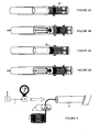
Figures 1A and 1B depict a device of the invention in use during airflow detection; -
Figures 2A and 2B depict a device of the invention in use during cable arrival detection; -
Figures 3A and 3B depict an alternative embodiment of the invention; -
Figures 4A and 4B depict another alternative embodiment of the invention; -
Figure 5 depicts the main components of apparatus used in a blown fibre installation at the head end; -
Figure 6 depicts a device of the invention and its enclosure; and -
Figure 7 depicts a device of the invention with an alternative enclosure. -
Figures 1A and 1B depict a first embodiment of the invention based on detection of an electrical property change, in this example being an inductance change. It consists of a substantially cylindrical or tubular housing (20) which has one open end and one closed end. The open end is configured to connect with the mouth of the optical fibre tube at the remote end of the installation e.g. in a friction fit. The housing is fabricated from a non-metallic material, such as an injection-moulded plastic, which is relatively simple and cheap to manufacture. - A piston (26) is also generally tubular with one open end and one closed end, and is disposed substantially co-axially within the housing, where the piston. The open end of the piston faces the same direction as the open end of the housing. The piston is configured to slide along its longitudinal axis within the housing. It is fabricated from metal, or else includes metal elements e.g. it can consist of an injection-moulded plastic containing metal filings. An induction coil (24) capable of sensing the presence of a metallic object, is mounted on the external surface so that is surrounds the housing. The coil is part of a tunable oscillator circuit (22), which is connected to a signal processor (28) capable of detecting tones generated by the oscillator, which tones - and any tone changes - can be transmitted by a radio frequency (RF) transmitter (30). The induction coil (24) and the piston (26) are positioned relative to each other so that they may move in and out of proximity of each other, such that the presence of the metallic properties of the piston changes the electrical characteristics of the coil, primarily its induction, which in turn changes the properties of the oscillator, specifically the tuning, which changes the frequency of the tone it produces. In alternative embodiments the frequency of the tone produced by the oscillator may be unchanged by the proximity of the piston to the coil. In those embodiments the change in the electrical characteristics of the coil produced by the proximity of the piston to the coil are designed preferably to change the amplitude or the phase, or both, of the tone produced by the oscillator. In all of these embodiments the change in the frequency, amplitude or phase of the tone produced by the oscillator is the indicator that signifies the arrival of air and/or the fibre unit at the remote end of the conduit. This applies to all the descriptions below in which a change in frequency only of the oscillator tone is given as example.
- The housing (20) and the piston (26) each include a set of air vents. The air vents of the piston (32) align with the air vents of the housing (34) when the piston is in a specific position within the housing.
- In the space between the closed end of the piston and the closed end of the housing is an arrangement to hold the piston in one of two positions: the first "rest" position being that the metallic piston (26) is located proximate to the induction coil (24) as shown in
Figure 1A , and the second "activated" position being where the two sets of air vents (32/34) are in alignment as shown inFigure 1B . The piston is configured to slide between these two positions within the housing. The arrangement comprises a spring (40) extending from the closed end of the housing, which holds the piston in the first rest position. The second activated position is obtained by the cooperation of a metal disc (36) and a magnet (38). - In the embodiment shown, the metal disc is disposed on the closed end of the piston and the magnet on the closed end of the housing although of course the locations of these two components may be reversed. Although the piston is made partially or even fully of metal, the metal disc may be required in practice to ensure that the attraction of the piston assembly to the magnet is sufficiently strong. As the purpose of this assembly is to hold the piston in the second activated position, it would be possible to use any suitable alternative that would achieve this end, e.g. a springloaded latch actuated by the travel of the piston.
- A plunger rod (44) connected to the closed end of the piston is pushed outwardly of the device when the piston is in the activated position, and a button (42) located at the end of the rod allows for the piston to be re-set to the rest position by the operator pressing the same to disengage the magnet and the metal disc sufficiently for the spring to urge the piston back in the first, resting position.
- The use of the device to sense a flow of air from the mouth of the conduit at the remote or far end of a blown fibre installation will now be described. At the start of the installation operation, the operator travels to the remote or destination end of the installation, and connects the above device to the mouth of the conduit from which it is hoped that the compressed air fed from the head end, will emerge. The device is set (or reset using the button (42)) so that it is in the first rest position, where the piston (26) is in proximity with, and actuates, the induction coil (24), and the air vents (34 and 36) are out of alignment, as shown in
Figure 1A . The oscillator circuit (22) thus outputs a tone of a specific frequency "A" indicative of the specific location of the metallic piston in the rest position or state. This is transmitted by RF as a status signal indicate that the sensor is active and functioning, and that the piston is in the correct rest position, to the operator when he arrives at the head end of the installation, which may be a kilometre or more away. This provides assurance that the device of the invention is working before starting the installation operation. - The operator chooses a conduit opening to direct pressurised air from an air compressor into. At the start of the blown fibre installation, the air pressure in and along the conduit is at a steady state level and air flow is zero. If the air is directed into the correct conduit opening, air eventually flows through to the remote end of the conduit, and into the housing (20) of the device. Because the two sets of air vents (32 and 34) are out of alignment, the housing is substantially air-tight. The increase in air pressure (e.g. up to 10 bar) within the housing caused by the air flow, gradually exceeds the pushing force of the spring (40) and causes the piston to slide towards the second, activated position. During this, the proximity of the metal disc (36) to the magnet (38) located opposite ends to each other increases. When the magnetic attraction between these two components eventually exceeds the force of air pressure within the main section of the housing and the opposing force of the spring, the piston snaps to take the second activated position shown in
Figure 1B at which point the two components are magnetically coupled together. - In the activated position, the two sets of air vents (32 and 34) are in alignment so that the air flow into the housing exhausts to the atmosphere as depicted by the arrows in
Figure 1B , resulting in a reduction of the air pressure within the housing. The force opposing that of the spring is now removed and the force of the air flow through the housing is insufficient in itself to hold the piston in that location, but the magnet arrangement helps holds the piston in the activated position. At this stage, the steady air flow through the conduit essential to the blown fibre installation procedure, is attained. - In the travel in the metallic piston from the resting to the activated position, the piston moves out of the immediate range of the induction coil (24). This changes the frequency of the tone produced by the oscillator (22). Depending on design considerations, the tone will either increase or decrease to a new frequency "B" generated by the piston's location at the activated position. In practice the change in the frequency of the tone will be relatively rapid and abrupt because of the increasing magnetic pull causing the piston to eventually snap to the activated position. In any event, frequency "B" will be distinguishable from frequency "A". The new frequency is detected and a corresponding status signal is automatically transmitted to the operator at the head end via the radio channel or by other means. The operator can at that point be assured that compressed air is being fed into the correct conduit mouth at the head end.
- Of course, if the operator did not feed the air down the correct conduit, none of the above will occur. In such a case, the operator will realise, from not receiving any signal from the remote end after a suitable time period, that something is amiss. He can then take appropriate steps e.g. selecting another conduit end to connect to the air compressor. He will at least be aware that the fibre unit should not be installed into the first-chosen tube.
- The use of the device to further sense the arrival of a fibre unit fed into the mouth of the conduit at the remote or far end of a blown fibre installation will now be described with reference to
Figures 2A and 2B . - First, a supply of fibre unit is prepared by crimping or otherwise crimping a slug or a bead (6) to the tip of one end, which protects the fragile glass fibre from damage. The bead typically has a rounded end which eases the fibre unit's progress through the conduit path. It is often made from, or includes, metal; brass is a preferred material as it does not rust.
- After the operator at the head end receives confirmation by RF or by e.g. a short message service text message that air is flowing from the desired destination conduit, a fibre unit (2) is fed into the same conduit (4) into which the compressed air is being fed.
- When the fibre unit (2) led by the metallic bead (6) advances out of the conduit opening at the remote end into the housing of the device as shown in
Figures 2A and 2B , the electrical properties of the induction coil (24) change which causes the oscillator's tone to shift from frequency "B" to a new frequency "C". It is possible for the value of frequency "C" to be substantially the same as that for frequency "A" without affecting the operation of the sensor, as long as the oscillator tone (22) clearly and distinguishably changes when the bead signifying the fibre unit arrives within proximity of the induction coil. - Unlike the relatively abrupt frequency change pattern in the air-detection step described above against
Figure 1 , the change from frequency "B" to frequency "C" inFigure 2 is more gradual, and the frequency change peaks quickly and momentarily as the bead advances past the induction coil and embeds in the piston beyond the immediate vicinity of the coil. The frequency thus changes momentarily from frequency "B" to frequency "C" and then back to substantially "B" again. The signal processor (28) accommodates these different characteristics and delivers (30) an unambiguous status signal to the operator at the head end, who then knows that the fibre cable has arrived and that the installation is complete. - The blowing head can then be tuned off, either manually by the operator, or in a further embodiment the receipt of the status signal could be linked to the blowing head so that the blowing head can be automatically switched off on receipt of the signal as further discussed below against
Figure 5 . At this point, the operator travels back to the remote site to remove the device from the conduit ending, and to reset it by pushing the button (42) so that the piston within the housing returns to its rest position for the device's next use. - As the skilled person would be aware, the components of the device can be used in various combinations and can be substituted by various other components. Some exemplary embodiments will now be discussed.
-
Figures 3 and 4 show embodiments of the invention in which only a portion of the piston comprises metal, as compared with the embodiment discussed againstFigures 1 and 2 where the whole piston consisted of, or included, metal. Specifically, the piston includes a band of metal, or metal constituents (50). The embodiments shown inFigure 3 ad 4 are equally effective to cause a frequency change when the piston in each case is caused to slide to the activated position upon an increase in air pressure within the housing chamber: the metal band moves out of the immediate detection zone of the induction coil in the case of the device of e.g.Figure 3A , while the metal band moves into the immediate vicinity of the coil in the case of the device ofFigure 4 . In the case of the device ofFigure 4 however, it should be noted that the persistent presence of the metal band in the immediate vicinity of the coil in the activated state may result in a smaller and less easily-detected frequency change upon arrival of the fibre unit, caused by the metal bead at the leading end of the fibre unit. - The skilled person would also realise that the band (50) and the induction coil (24) can be placed at various locations along the length of the housing, so as to obtain different results and effects. For example, an induction coil can be placed near the end of the device in the immediate proximity of the terminal location within the housing where the bead will rest, to provide a clear continuous signal to the operator that the fibre bead has arrived at the remote end of the installation. This could be a second or further coil in addition to a first which is located at the position shown in e.g.
Figure 1 . The plunger rod (44) arrangement and reset button (42) are optional to the operation of the device, and may not be needed in a disposable version of the device. The spring (40) can be replaced by any resilient/biasing component which urges the piston to the first resting position. - In a preferred embodiment of the invention, the pushing force of the spring against the piston can be pre-selected so that the piston is caused to travel only when air pressure within the housing reaches a pre-determined level. Preferably, this air pressure level should approximate that of the air applied at the head end: by way of example, the applicants feed air compressed to 10 bar into the tube. This allows the operator to start the fibre installation process only when the desired air pressure level is attained within the conduit, as blown fibre may not propagate successfully through the tube if there is insufficient air flow therein. In further embodiments, the resilience level of the spring may be adjustable or selected, and can be used to measure air pressure levels within the housing during an installation.
- As noted above, the detection of the presence or absence of the metallic piston and/or bead within the housing can be achieved by sensing or measuring changes in other electrical properties or characteristics of the detector, such as its capacitance, its Q factor, resistance, or the like.
- As a further design consideration, the force of the spring in the activated position should be less than the magnetic force holding the piston in place. Furthermore, the coupling strength of the magnetic arrangement should be sufficiently robust to avoid the piston accidentally springing back to the resting position, yet allow for the device to be reset by an operator without too much difficulty after an installation.
- In certain embodiments, the movement of the piston itself can be detected as signifying the presence of air and/or the fibre unit in the device. In such examples, the movement away from the first resting position can itself be sensed to indicate e.g. an airflow within the housing. A subsequent movement (which could be in the same direction as the first movement away from the first position, or in the reverse or other direction) could be sensed as a further indication of e.g. fibre unit arrival within the housing. For example, the piston could be urged away from the first rest position upon air arrival, and the bead of the fibre unit could push it to the second, further position indicating its presence in the housing.
-
Figure 5 depicts the main apparatus components located at the head end of the optical fibre conduit or tube, where the operator is located. There, he operates a blowing head which controls the forces propelling an optical fibre unit (2) into the conduit or tube (4), which forces comprise a pair of drive wheels (6) and a supply of pressurised air (8) typically from a compressor. The drive wheels mechanically drive the fibre unit into the tube, while the compressed air is fed into the conduit to create within it the laminar air flow which will bear the fibre unit along and through the tube. - The blowing head may be capable of detecting that the fibre unit is no longer progressing through the tube - which could be a result of the fibre arriving at the remote end, or else it is otherwise caught or stuck within the tube. In response, the blowing head stops the drive wheels from further pushing the fibre unit into the tube. The receipt (or non-receipt) of confirmation that the fibre bead has arrived at the remote end via the radio receiver (5) allows the operator to decide what to do next: to end the successful installation, or else to take remedial action.
- In a preferred embodiment, the head end apparatus (in the main, the blowing head and the air compressor) is configured to respond (7) to the receipt of a signal indicative of fibre arrival at the remote end, by terminating the installation session e.g. by turning themselves off, or going into a standby mode. There is a particular synergy in doing so in the case of the blowing head, due to this component's already-existing capability to sense lack of further progress of the fibre within the tube: receipt of the fibre arrival signal confirms the cause of the lack of fibre progress. Similarly, the apparatus at the head end could be configured to respond to the initial signal that air is flowing from the remote end conduit, by automatically starting the fibre installation process.
-
Figures 6 and 7 depict two embodiments of the full enclosure surrounding the device, which may be about 8cm long for use with a conduit having an external diameter of typically 3mm in the case of small-bore conduits, up to 15mm and more for large bore conduits. In a preferred embodiment the coupling flange fixed to the device housing may be adjustable to tightly fit the conduit in use, or the coupling flange may be removable from the housing whereupon the another flange size suitable for the conduit in use is selected for attachment to the housing. In either case the flange ensures mechanically robust and substantially airtight coupling between the housing (20) and the conduit (4). - In
Figure 6 , the device comprises two injection moulded plastic sections: the inner tubular housing (20), and the outer enclosure (52). Fine gauze dust shields (60) are provided on the air vent openings (32 and 34) to prevent or discourage contamination of the interior of the device. The outer enclosure is configured to avoid the air vents so that the arriving air vents to atmosphere and allows essential air flow along the conduit. The reset button (42) is also located outside the outer enclosure. Once assembled, the only service-removable part is the battery cover protecting the dry cell battery (56) on the outer enclosure surface. Should it be found desirable to replace the dust shields, then they too could be made to be service-removable. A minimal number of service-removable parts is however advantageous for easy maintenance. - An internal antenna (54) used for transmitting signals about air and fibre arrival to the head end, may be incorporated within the enclosure, or alternatively an external antenna (55) could be used for greater range/gain in operational situations where radio reception may be impaired (e.g. down a manhole). Ideally, the fibre conduit at the remote end is long enough to extend the fibre conduit route to ground/surface level for the purposes of the installation process, in which case radio reception is improved and a reliable channel may be established with the head end operator. Should there be insufficient length of conduit, a bridging length of conduit can be temporarily attached for purposes of the installation.
-
Figure 7 shows an alternative outer enclosure (62) consisting a simple injection-moulded box. In this implementation, only the reset button (42) stands proud of the outer enclosure. All the other elements of the device can be enclosed, even the air vent openings (32 and 34), although the gauze dust shields (60) must be configured to allow for sufficient air flow through the conduit and out of the device for purposes of the blown fibre installation session. - The methods, devices, components and configurations described above and in the drawings are for ease of description only and not meant to restrict the invention to any particular embodiments. It will be apparent to the skilled person that various sequences and permutations on the methods and devices described are possible within the scope of this invention as disclosed; similarly the invention could be used in various similar scenarios and for various cable and conduit types and sizes. In particular, the apparatus and methods relating to air flow detection and the methods and apparatus relating to fibre arrival detection are depicted in this description to be used together in a preferred embodiment. However they will work independently of each other on their own, to realise the advantages of the respective inventions.
Claims (22)
- A device for use with a conduit having a first conduit end and a conduit second end, into which conduit a cable can be installed using a flow of air into the first conduit end, the device being suitable for confirming that the air is flowing out from the second conduit end, the device comprising- a housing,- means to enable connection of the device to the second conduit end,- a detector arranged to detect an electrical property change, and- an actuator for causing an electrical property change detectable by the detector,wherein in use, the air flowing into the device causes the detector and the actuator to move relative to each other, causing an electrical property change detectable by the detector.
- A device according to claim 1 wherein the detector comprises at least one of an induction coil or a capacitor being part of an oscillator, connected to a signal processor for detecting tones generated by the oscillator, the device further comprising a transmitter for transmitting a signal comprising the detected tones.
- A device according to claim 1 or claim 2 wherein the actuator is arranged to move within the housing, and comprises or includes a metallic element.
- A device according to any preceding claim further including holding means to hold the actuator in one of either a first position or a second position, wherein movement between the first position and the second position causes the electrical property change.
- A device according to any preceding claim wherein the holding means to hold the actuator in the first position comprises a spring urging against the actuator.
- A device according to claim 5 wherein the holding means to hold the actuator in the second position comprises means causing compression of the spring.
- A device according to claim 6 wherein the holding means comprises a magnet and a metal disc disposed opposite to each other.
- A device according to claim 7 wherein in use, the air flowing into the device causes the magnet and the metal disc to move towards each other and then to be magnetically coupled together.
- A device according to any preceding claim further including an air vent through which in use, the air flows when the actuator is held in the second position.
- A device according to any preceding claim further including means to return the actuator to the first position from the second position.
- A device according to any preceding claim wherein the actuator is detected by the detector when the actuator is held in the first position.
- A device according to any preceding claim further being suitable for confirming that the cable has arrived at the second conduit end, wherein the detector is arranged to detect a further inductance change caused by the detected presence of a bead including a metallic component connected to a fibre unit.
- A device for use with a conduit having a first conduit end and a conduit second end, into which conduit a cable can be installed using a flow of air into the first conduit end, the device being suitable for confirming that the air is flowing out from the second conduit end, the device comprising- a housing,- means to enable connection of the device to the second conduit end,- a piston moveably located within the housing, and- a detector for detecting a change in a position of the piston,wherein in use, the air flowing into the device causes a change in the position of the piston within the housing, which is detected by the detector.
- A device according to claim 13 further being suitable for confirming that the cable has arrived at the second conduit end, wherein the detector is arranged to detect a further change in the position of the piston caused by travel of a bead connected to a fibre unit within the housing.
- A system for use with a conduit having a first conduit end and a conduit second end, into which conduit a cable can be installed using a flow of air into the first conduit end, comprising a device for confirming that the air is flowing out from the second conduit end according to any preceding claim.
- A system according to claim 15 including a device of any preceding claim wherein apparatus at the first conduit end is configured to receive and to automatically respond to the detected change.
- A method for use with a conduit having a first conduit end and a conduit second end, into which conduit a cable can be installed using a flow of air into the first conduit end, and to confirm that the air is flowing out of the from the second conduit end, the method comprising- attaching a device of any one of claims 1 to 12 to the second conduit end,- applying the flow of air into the first conduit end,- causing the actuator of the device to move relative to the detector of the device, and- causing an electrical property change detected by the detector.
- A method for use with a conduit having a first conduit end and a conduit second end, into which conduit a cable can be installed using a flow of air into the first conduit end, and to confirm that the air is flowing out of the from the second conduit end, the method comprising- attaching a device of claim 13 to the second conduit end,- applying the flow of air into the first conduit end, and- detecting with the detector a change in the position of the piston within the housing caused by the flow of air.
- A method according to claim 17 or claim 18 using the device of any one of claims 1 to 14, further including the step of transmitting a signal based on the detected change.
- A method according to claim 17 to further confirm that the cable has arrived at the second conduit end, including- connecting a bead to an end of the cable,- installing the cable into the first conduit end, and- causing a further electrical property change detected by the detector.
- A method according to claim 18 to further confirm that the cable has arrived at the second conduit end, including- connecting a bead to an end of the cable,- installing the cable into the first conduit end, and- causing a further change in position of the piston within the housing detected by the detector.
- A method according to claim 20 or claim 21 further including- transmitting a signal comprising the further detected change to apparatus located at the first conduit end, and- causing the apparatus at the first conduit end to automatically respond to the transmitted signal.
Priority Applications (4)
| Application Number | Priority Date | Filing Date | Title |
|---|---|---|---|
| EP07255067A EP2075606A1 (en) | 2007-12-28 | 2007-12-28 | Cable installation using induction |
| US12/810,731 US8587327B2 (en) | 2007-12-28 | 2008-12-23 | Cable installation using induction |
| EP08867892.5A EP2225597B1 (en) | 2007-12-28 | 2008-12-23 | Cable installation using induction |
| PCT/GB2008/004277 WO2009083718A1 (en) | 2007-12-28 | 2008-12-23 | Cable installation using induction |
Applications Claiming Priority (1)
| Application Number | Priority Date | Filing Date | Title |
|---|---|---|---|
| EP07255067A EP2075606A1 (en) | 2007-12-28 | 2007-12-28 | Cable installation using induction |
Publications (1)
| Publication Number | Publication Date |
|---|---|
| EP2075606A1 true EP2075606A1 (en) | 2009-07-01 |
Family
ID=39522014
Family Applications (2)
| Application Number | Title | Priority Date | Filing Date |
|---|---|---|---|
| EP07255067A Ceased EP2075606A1 (en) | 2007-12-28 | 2007-12-28 | Cable installation using induction |
| EP08867892.5A Active EP2225597B1 (en) | 2007-12-28 | 2008-12-23 | Cable installation using induction |
Family Applications After (1)
| Application Number | Title | Priority Date | Filing Date |
|---|---|---|---|
| EP08867892.5A Active EP2225597B1 (en) | 2007-12-28 | 2008-12-23 | Cable installation using induction |
Country Status (3)
| Country | Link |
|---|---|
| US (1) | US8587327B2 (en) |
| EP (2) | EP2075606A1 (en) |
| WO (1) | WO2009083718A1 (en) |
Cited By (1)
| Publication number | Priority date | Publication date | Assignee | Title |
|---|---|---|---|---|
| RU2572802C1 (en) * | 2014-11-20 | 2016-01-20 | Общество с ограниченной ответственностью "Инженерно-технический центр инновационных технологий" (ООО "Центр ИТ") | Method of cable insertion in ferromagnetic pipe, and device for its implementation |
Families Citing this family (9)
| Publication number | Priority date | Publication date | Assignee | Title |
|---|---|---|---|---|
| EP1832908A1 (en) * | 2006-03-10 | 2007-09-12 | BRITISH TELECOMMUNICATIONS public limited company | Cable installation |
| EP1914577A1 (en) * | 2006-10-17 | 2008-04-23 | British Telecommunications Public Limited Company | Optical fibre installation apparatus |
| EP2075608A1 (en) * | 2007-12-28 | 2009-07-01 | British Telecmmunications public limited campany | Cable installation using optical detection |
| GB0817639D0 (en) | 2008-09-26 | 2008-11-05 | British Telecomm | Cable installation apparatus |
| EP2230545A1 (en) | 2009-03-19 | 2010-09-22 | BRITISH TELECOMMUNICATIONS public limited company | Passive remote air flow and cable detection |
| GB0905590D0 (en) | 2009-03-31 | 2009-05-13 | British Telecomm | Blown cable apparatus |
| EP2369388A1 (en) | 2010-03-26 | 2011-09-28 | British Telecommunications public limited company | Optical fibre splice tray assembly |
| US10144860B1 (en) * | 2017-07-20 | 2018-12-04 | Saudi Arabian Oil Company | Loss circulation compositions (LCM) having portland cement clinker |
| FR3167456A1 (en) * | 2024-10-11 | 2026-04-17 | Technipfmc Subsea France | Device for installing and/or removing an optical fiber in a receiving tube of a flexible fluid transport pipe, assembly and associated method |
Citations (9)
| Publication number | Priority date | Publication date | Assignee | Title |
|---|---|---|---|---|
| EP0108590A1 (en) | 1982-11-08 | 1984-05-16 | BRITISH TELECOMMUNICATIONS public limited company | Optical fibre transmission lines |
| WO1988000713A1 (en) | 1986-07-16 | 1988-01-28 | British Telecommunications Public Limited Company | Control method and apparatus |
| GB2219662A (en) * | 1988-06-06 | 1989-12-13 | Daido Metal Co | Fluid flow detector |
| WO1991003756A1 (en) | 1989-09-04 | 1991-03-21 | British Telecommunications Public Limited Company | Remote end detection |
| WO1998012588A1 (en) | 1996-09-19 | 1998-03-26 | British Telecommunications Public Limited Company | Blowing head |
| EP1022569A1 (en) * | 1999-01-19 | 2000-07-26 | FUGAS s.r.l. | A magnetically operated liquid flow detector and a hydraulic group incorporating the same |
| WO2006103419A1 (en) | 2005-03-31 | 2006-10-05 | British Telecommunications Public Limited Company | Optical fibre installation apparatus |
| US20060219992A1 (en) * | 2005-04-01 | 2006-10-05 | Mci, Inc. | Systems and methods for controlling duct pressurization for cable installation |
| EP1843181A1 (en) * | 2006-04-03 | 2007-10-10 | British Telecommunications Public Limited Company | Cable installation |
Family Cites Families (85)
| Publication number | Priority date | Publication date | Assignee | Title |
|---|---|---|---|---|
| US3814935A (en) | 1973-01-24 | 1974-06-04 | Chrysler Corp | Photo-optical transducer |
| JPS5620763A (en) | 1979-07-31 | 1981-02-26 | Nissan Motor Co Ltd | Controller for internal combustion engine |
| DE3012638C2 (en) | 1980-04-01 | 1981-12-17 | Standard Elektrik Lorenz Ag, 7000 Stuttgart | Fiber optic cable with means to enable location |
| SU1000750A1 (en) | 1981-11-17 | 1983-02-28 | За витель (.54) ПНЕВМАТИЧЕСКИЙ СПОСОБ ИЗМЕРЕНИЯ СРЕДНЕГО даДМЕТРА , л , , А.Ф.МизтаЦ в ) .В.&ЛОф {з в / / . - / . , /-4 i,-.., i .. КАПИЛЛЯРА | Pneumatic method of measuring capillary average diameter |
| US5169126C1 (en) | 1982-11-08 | 2001-05-08 | British Telecomm | Method and apparatus for installing transmission lines |
| US4471651A (en) | 1982-11-12 | 1984-09-18 | Mark Telephone Products, Inc. | Duct probe and dispensing apparatus therefor |
| CA1309240C (en) | 1987-03-20 | 1992-10-27 | Minoru Seino | Method of connecting optical fibers |
| NL193126B (en) | 1987-04-28 | 1998-07-01 | Nederland Ptt | Method and device for arranging a cable in a cable guide tube. |
| GB2205916B (en) | 1987-06-04 | 1991-04-17 | British Pipeline Agency | Pipeline systems |
| GB8727579D0 (en) | 1987-11-25 | 1987-12-31 | Bicc Plc | Method & apparatus for conveying optical fibre member |
| DE3743470C1 (en) | 1987-12-22 | 1989-03-09 | Kabelmetal Electro Gmbh | Method of making a cable |
| GB8813068D0 (en) | 1988-06-02 | 1988-07-06 | British Telecomm | Transmission line installation |
| GB2241120B (en) | 1990-02-14 | 1994-01-19 | Stc Plc | Deploying cables in pipelines |
| JPH03249704A (en) | 1990-02-28 | 1991-11-07 | Sumitomo Electric Ind Ltd | Method and device for laying optical fiber unit |
| NL9001618A (en) | 1990-07-17 | 1992-02-17 | Nederland Ptt | METHOD AND APPARATUS FOR INSTALLING A CABLE IN A CABLE PRODUCT. |
| JP2943346B2 (en) | 1991-01-25 | 1999-08-30 | 住友電気工業株式会社 | How to lay wires |
| DE4202147A1 (en) | 1992-01-27 | 1993-07-29 | Lancier Masch Peter | Feeding a cable into a conduit using compressed air - requires cable attached to piston blown down conduit by compressed with air measuring head recording speed and force |
| JP3044422B2 (en) | 1992-05-25 | 2000-05-22 | 嘉明 花塚 | Cable laying method |
| US5749565A (en) | 1994-03-02 | 1998-05-12 | British Telecommunications Public Limited Company | Optical fibre installation tool |
| US5573225A (en) | 1994-05-06 | 1996-11-12 | Dowell, A Division Of Schlumberger Technology Corporation | Means for placing cable within coiled tubing |
| US5813658A (en) | 1994-11-23 | 1998-09-29 | Arnco Corporation | Cable feeding apparatus |
| JP2849983B2 (en) | 1994-12-05 | 1999-01-27 | 加藤 正 | Cable laying method and cable laying device |
| JPH08178722A (en) | 1994-12-26 | 1996-07-12 | Nissan Motor Co Ltd | Method for detecting flow direction of intake air amount sensor of internal combustion engine and intake air amount sensor of internal combustion engine |
| FR2737053B1 (en) | 1995-07-21 | 1997-10-10 | Vettor Christian | TUBE INPUT / OUTPUT ACOUSTIC IDENTIFICATION METHOD |
| US5897103A (en) | 1995-07-24 | 1999-04-27 | Koninklijke Ptt Nederland N.V. | Method for installing cables |
| US5953475A (en) | 1995-09-01 | 1999-09-14 | Siemens Aktiengesellschaft | Fiber optic plug connector |
| US5835657A (en) | 1995-12-08 | 1998-11-10 | Psi Telecommunications, Inc. | Fiber optic splice tray |
| GB2316496B (en) | 1996-08-09 | 2000-07-26 | Bowthorpe Plc | Optical fibre storage enclosure |
| US6891317B2 (en) * | 2001-05-22 | 2005-05-10 | Sri International | Rolled electroactive polymers |
| GB2325531A (en) | 1997-05-19 | 1998-11-25 | Pirelli General Plc | Optical fibre connector organiser |
| US6012621A (en) | 1997-09-04 | 2000-01-11 | Condux International, Inc. | Cable conveying apparatus |
| GB9820535D0 (en) | 1998-09-21 | 1998-11-11 | Radiodetection Ltd | Identification and location of fibre optic cables |
| NL1010270C2 (en) | 1998-10-08 | 2000-04-11 | Koninkl Kpn Nv | A method of installing cables in tubes by means of a pressurized fluid and apparatus for carrying out this method. |
| JP2000217216A (en) | 1999-01-21 | 2000-08-04 | Sumitomo Electric Ind Ltd | Cable pressure line connection adapter, cable pressure line and cable pressure line installation method |
| SE9900623L (en) | 1999-02-22 | 2000-06-26 | Ericsson Telefon Ab L M | Optical fiber feed device |
| GB9909912D0 (en) | 1999-04-29 | 1999-06-30 | Pirelli General Plc | Method of blowing cable into a duct |
| EP1191354A1 (en) | 2000-09-20 | 2002-03-27 | Dipl.-Ing. Dr. Ernst Vogelsang GmbH & Co. KG | Device for identifying and/or locating buried cables for optical information exchange, in particular opticle fibre cables |
| JP2004523731A (en) * | 2000-10-16 | 2004-08-05 | イー・アイ・デュポン・ドウ・ヌムール・アンド・カンパニー | Method and apparatus for analyzing a mixture of gases |
| JP4240806B2 (en) | 2000-12-22 | 2009-03-18 | 三菱重工業株式会社 | Fuel cell |
| US6930496B2 (en) * | 2001-01-17 | 2005-08-16 | Henry O. Walcott | Range resistors for AC-DC transfer measurements |
| CA2342092A1 (en) * | 2001-03-23 | 2002-09-23 | Vibrosystm Inc. | Non intrusive and dynamic method and system for measuring a distance or the variation thereof through dielectrics |
| US20020158239A1 (en) | 2001-03-30 | 2002-10-31 | Nkf Kabel B.V. | Optical cable installation with mini-bend reduction |
| US6937033B2 (en) * | 2001-06-27 | 2005-08-30 | Immersion Corporation | Position sensor with resistive element |
| DE10131752A1 (en) | 2001-07-03 | 2003-01-23 | Univ Braunschweig Tech Carolo Wilhelmina | Arrangement and method for measuring the gas permeability of a porous building material |
| AU2002356882A1 (en) | 2001-11-02 | 2003-05-19 | Neptco Inc. | Apparatus and methods for applying media to a conduit |
| AT411498B (en) | 2002-01-31 | 2004-01-26 | Moeller Gebaeudeautomation Kg | MANAGEMENTSPLEISSKASSETTE |
| GB2388966A (en) | 2002-05-24 | 2003-11-26 | Cbs Products Ltd | Cable blowing machine |
| US6853305B2 (en) * | 2002-05-28 | 2005-02-08 | International Business Machines Corporation | Air-conduit condensation sensor |
| US6848541B2 (en) | 2002-07-11 | 2005-02-01 | Nkf Kabel B.V. | Optical cable installation with cable lubricator |
| US6992580B2 (en) | 2002-07-25 | 2006-01-31 | Motorola, Inc. | Portable communication device and corresponding method of operation |
| DE10338950A1 (en) | 2003-08-25 | 2005-06-23 | Jäger, Frank-Michael | Method for detecting pigs in oil pipelines uses acoustic sensors mounted on outside of pipe wall to detect interruption of ultrasound signals reflected from inside of pipe and to detect signal from acoustic unit on pig |
| US7408474B2 (en) | 2003-12-16 | 2008-08-05 | Leitner-Poma Of America, Inc. | Sensor damage indicator and method |
| US7200314B2 (en) | 2004-05-06 | 2007-04-03 | Commscope Solutions Properties, Llc | Carrier for multiple splice trays |
| FR2872299A1 (en) | 2004-06-24 | 2005-12-30 | France Telecom | OPTICAL MICRO-CABLE TRAINER WITH REDUCED SIZE |
| GB0506568D0 (en) | 2005-03-31 | 2005-05-04 | British Telecomm | Optical fibre air chamber apparatus |
| US7460758B2 (en) | 2005-06-03 | 2008-12-02 | Telect Inc. | Fiber management system |
| US7352945B2 (en) | 2005-08-29 | 2008-04-01 | Adc Telecommunications, Inc. | Outside plant enclosure with pivoting fiber trays |
| EP1949161A1 (en) | 2005-10-24 | 2008-07-30 | Tyco Electronics Corporation | Fiber optic splice storage apparatus and methods for using the same |
| EP1832903A1 (en) | 2006-03-09 | 2007-09-12 | BRITISH TELECOMMUNICATIONS public limited company | Cable installation |
| EP1832908A1 (en) | 2006-03-10 | 2007-09-12 | BRITISH TELECOMMUNICATIONS public limited company | Cable installation |
| EP1994436B1 (en) * | 2006-03-10 | 2020-02-19 | British Telecommunications public limited company | Cable installation |
| WO2007113549A1 (en) | 2006-04-03 | 2007-10-11 | British Telecommunications Public Limited Company | Cable installation |
| US20090242860A1 (en) * | 2006-04-03 | 2009-10-01 | Barker Philip A | Cable installation |
| AU2006343084B2 (en) * | 2006-04-25 | 2012-12-20 | Mitsubishi Chemical Corporation | Water based emulsion and use thereof |
| US20080011990A1 (en) | 2006-07-14 | 2008-01-17 | Tenvera, Inc. | Installation of Fiber Optic Cables |
| US20080013893A1 (en) | 2006-07-14 | 2008-01-17 | Tenvera, Inc. | Optical Fiber Ferrule and Ferrule Receiver, and Method for Manufacturing the Same |
| US7349615B2 (en) | 2006-08-25 | 2008-03-25 | Corning Cable Systems Llc | Fiber optic housing assembly for fiber optic connections comprising pivotable portion |
| EP1914577A1 (en) | 2006-10-17 | 2008-04-23 | British Telecommunications Public Limited Company | Optical fibre installation apparatus |
| EP1978389A1 (en) | 2007-04-02 | 2008-10-08 | BRITISH TELECOMMUNICATIONS public limited company | Blown cable installation |
| US8413964B2 (en) | 2007-12-28 | 2013-04-09 | Verizon Patent And Licensing Inc. | Fiber drop installation device |
| EP2075608A1 (en) * | 2007-12-28 | 2009-07-01 | British Telecmmunications public limited campany | Cable installation using optical detection |
| EP2075607A1 (en) | 2007-12-28 | 2009-07-01 | British Telecmmunications public limited campany | Arrival detection of air flow and a fibre unit during fibre blowing installation using relfected light |
| EP2075609A1 (en) | 2007-12-28 | 2009-07-01 | British Telecmmunications public limited campany | Cable installation detection using air flow |
| US8009954B2 (en) | 2008-04-21 | 2011-08-30 | Adc Telecommunications, Inc. | Fiber optic splice tray |
| EP2131222A1 (en) * | 2008-06-06 | 2009-12-09 | BRITISH TELECOMMUNICATIONS public limited company | Exchange cabling method and apparatus |
| EP2157463A1 (en) | 2008-07-11 | 2010-02-24 | BRITISH TELECOMMUNICATIONS public limited company | Cable installation detection component |
| GB0817639D0 (en) | 2008-09-26 | 2008-11-05 | British Telecomm | Cable installation apparatus |
| EP2230545A1 (en) | 2009-03-19 | 2010-09-22 | BRITISH TELECOMMUNICATIONS public limited company | Passive remote air flow and cable detection |
| GB0905590D0 (en) * | 2009-03-31 | 2009-05-13 | British Telecomm | Blown cable apparatus |
| US8117923B2 (en) * | 2009-05-08 | 2012-02-21 | Shimano Inc. | Bicycle bottom bracket force sensor |
| TWI369466B (en) | 2009-07-14 | 2012-08-01 | Ind Tech Res Inst | Fluid whirl lighting apparatus |
| US8350581B1 (en) * | 2009-08-27 | 2013-01-08 | The Boeing Company | Nondestructive inspection to quantify degradation of cylindrical objects made of polymer materials |
| US8310249B2 (en) * | 2009-09-17 | 2012-11-13 | Woodward, Inc. | Surface gap soot sensor for exhaust |
| WO2011041780A2 (en) * | 2009-10-02 | 2011-04-07 | The Controls Group, Inc. | Removal of an accumulated frozen substance from a cooling unit |
| EP2369388A1 (en) | 2010-03-26 | 2011-09-28 | British Telecommunications public limited company | Optical fibre splice tray assembly |
-
2007
- 2007-12-28 EP EP07255067A patent/EP2075606A1/en not_active Ceased
-
2008
- 2008-12-23 WO PCT/GB2008/004277 patent/WO2009083718A1/en not_active Ceased
- 2008-12-23 EP EP08867892.5A patent/EP2225597B1/en active Active
- 2008-12-23 US US12/810,731 patent/US8587327B2/en active Active
Patent Citations (10)
| Publication number | Priority date | Publication date | Assignee | Title |
|---|---|---|---|---|
| EP0108590A1 (en) | 1982-11-08 | 1984-05-16 | BRITISH TELECOMMUNICATIONS public limited company | Optical fibre transmission lines |
| WO1988000713A1 (en) | 1986-07-16 | 1988-01-28 | British Telecommunications Public Limited Company | Control method and apparatus |
| GB2219662A (en) * | 1988-06-06 | 1989-12-13 | Daido Metal Co | Fluid flow detector |
| WO1991003756A1 (en) | 1989-09-04 | 1991-03-21 | British Telecommunications Public Limited Company | Remote end detection |
| WO1998012588A1 (en) | 1996-09-19 | 1998-03-26 | British Telecommunications Public Limited Company | Blowing head |
| EP1022569A1 (en) * | 1999-01-19 | 2000-07-26 | FUGAS s.r.l. | A magnetically operated liquid flow detector and a hydraulic group incorporating the same |
| WO2006103419A1 (en) | 2005-03-31 | 2006-10-05 | British Telecommunications Public Limited Company | Optical fibre installation apparatus |
| US20060219992A1 (en) * | 2005-04-01 | 2006-10-05 | Mci, Inc. | Systems and methods for controlling duct pressurization for cable installation |
| EP1843181A1 (en) * | 2006-04-03 | 2007-10-10 | British Telecommunications Public Limited Company | Cable installation |
| WO2007113544A1 (en) | 2006-04-03 | 2007-10-11 | British Telecommunications Public Limited Company | Cable installation detection |
Cited By (1)
| Publication number | Priority date | Publication date | Assignee | Title |
|---|---|---|---|---|
| RU2572802C1 (en) * | 2014-11-20 | 2016-01-20 | Общество с ограниченной ответственностью "Инженерно-технический центр инновационных технологий" (ООО "Центр ИТ") | Method of cable insertion in ferromagnetic pipe, and device for its implementation |
Also Published As
| Publication number | Publication date |
|---|---|
| EP2225597A1 (en) | 2010-09-08 |
| US20110006786A1 (en) | 2011-01-13 |
| US8587327B2 (en) | 2013-11-19 |
| WO2009083718A1 (en) | 2009-07-09 |
| EP2225597B1 (en) | 2019-08-14 |
Similar Documents
| Publication | Publication Date | Title |
|---|---|---|
| EP2225597B1 (en) | Cable installation using induction | |
| EP2235574B1 (en) | Cable installation using optical detection | |
| US8276883B2 (en) | Cable installation | |
| US9762039B2 (en) | Cable installation detection | |
| EP2075609A1 (en) | Cable installation detection using air flow | |
| US8275227B2 (en) | Cable installation | |
| EP2347486B1 (en) | Cable installation apparatus | |
| EP1991893B1 (en) | Cable installation | |
| TWI344023B (en) | Apparatus and method for optical fibre installation | |
| EP2075607A1 (en) | Arrival detection of air flow and a fibre unit during fibre blowing installation using relfected light | |
| WO2007113549A1 (en) | Cable installation | |
| EP0585902B1 (en) | Method and apparatus for measuring length of conduit |
Legal Events
| Date | Code | Title | Description |
|---|---|---|---|
| PUAI | Public reference made under article 153(3) epc to a published international application that has entered the european phase |
Free format text: ORIGINAL CODE: 0009012 |
|
| AK | Designated contracting states |
Kind code of ref document: A1 Designated state(s): AT BE BG CH CY CZ DE DK EE ES FI FR GB GR HU IE IS IT LI LT LU LV MC MT NL PL PT RO SE SI SK TR |
|
| AX | Request for extension of the european patent |
Extension state: AL BA HR MK RS |
|
| STAA | Information on the status of an ep patent application or granted ep patent |
Free format text: STATUS: THE APPLICATION HAS BEEN REFUSED |
|
| 18R | Application refused |
Effective date: 20090723 |