EP2075436B1 - Ferry flight engine fairing kit - Google Patents
Ferry flight engine fairing kit Download PDFInfo
- Publication number
- EP2075436B1 EP2075436B1 EP08172249A EP08172249A EP2075436B1 EP 2075436 B1 EP2075436 B1 EP 2075436B1 EP 08172249 A EP08172249 A EP 08172249A EP 08172249 A EP08172249 A EP 08172249A EP 2075436 B1 EP2075436 B1 EP 2075436B1
- Authority
- EP
- European Patent Office
- Prior art keywords
- fairing
- gas turbine
- turbine engine
- kit
- core gas
- Prior art date
- Legal status (The legal status is an assumption and is not a legal conclusion. Google has not performed a legal analysis and makes no representation as to the accuracy of the status listed.)
- Expired - Fee Related
Links
Images


Classifications
-
- F—MECHANICAL ENGINEERING; LIGHTING; HEATING; WEAPONS; BLASTING
- F02—COMBUSTION ENGINES; HOT-GAS OR COMBUSTION-PRODUCT ENGINE PLANTS
- F02K—JET-PROPULSION PLANTS
- F02K3/00—Plants including a gas turbine driving a compressor or a ducted fan
-
- B—PERFORMING OPERATIONS; TRANSPORTING
- B64—AIRCRAFT; AVIATION; COSMONAUTICS
- B64F—GROUND OR AIRCRAFT-CARRIER-DECK INSTALLATIONS SPECIALLY ADAPTED FOR USE IN CONNECTION WITH AIRCRAFT; DESIGNING, MANUFACTURING, ASSEMBLING, CLEANING, MAINTAINING OR REPAIRING AIRCRAFT, NOT OTHERWISE PROVIDED FOR; HANDLING, TRANSPORTING, TESTING OR INSPECTING AIRCRAFT COMPONENTS, NOT OTHERWISE PROVIDED FOR
- B64F1/00—Ground or aircraft-carrier-deck installations
- B64F1/005—Protective coverings for aircraft not in use
-
- B—PERFORMING OPERATIONS; TRANSPORTING
- B64—AIRCRAFT; AVIATION; COSMONAUTICS
- B64F—GROUND OR AIRCRAFT-CARRIER-DECK INSTALLATIONS SPECIALLY ADAPTED FOR USE IN CONNECTION WITH AIRCRAFT; DESIGNING, MANUFACTURING, ASSEMBLING, CLEANING, MAINTAINING OR REPAIRING AIRCRAFT, NOT OTHERWISE PROVIDED FOR; HANDLING, TRANSPORTING, TESTING OR INSPECTING AIRCRAFT COMPONENTS, NOT OTHERWISE PROVIDED FOR
- B64F5/00—Designing, manufacturing, assembling, cleaning, maintaining or repairing aircraft, not otherwise provided for; Handling, transporting, testing or inspecting aircraft components, not otherwise provided for
- B64F5/50—Handling or transporting aircraft components
-
- F—MECHANICAL ENGINEERING; LIGHTING; HEATING; WEAPONS; BLASTING
- F01—MACHINES OR ENGINES IN GENERAL; ENGINE PLANTS IN GENERAL; STEAM ENGINES
- F01D—NON-POSITIVE DISPLACEMENT MACHINES OR ENGINES, e.g. STEAM TURBINES
- F01D25/00—Component parts, details, or accessories, not provided for in, or of interest apart from, other groups
- F01D25/28—Supporting or mounting arrangements, e.g. for turbine casing
- F01D25/285—Temporary support structures, e.g. for testing, assembling, installing, repairing; Assembly methods using such structures
-
- F—MECHANICAL ENGINEERING; LIGHTING; HEATING; WEAPONS; BLASTING
- F02—COMBUSTION ENGINES; HOT-GAS OR COMBUSTION-PRODUCT ENGINE PLANTS
- F02C—GAS-TURBINE PLANTS; AIR INTAKES FOR JET-PROPULSION PLANTS; CONTROLLING FUEL SUPPLY IN AIR-BREATHING JET-PROPULSION PLANTS
- F02C7/00—Features, components parts, details or accessories, not provided for in, or of interest apart form groups F02C1/00 - F02C6/00; Air intakes for jet-propulsion plants
- F02C7/20—Mounting or supporting of plant; Accommodating heat expansion or creep
-
- F—MECHANICAL ENGINEERING; LIGHTING; HEATING; WEAPONS; BLASTING
- F05—INDEXING SCHEMES RELATING TO ENGINES OR PUMPS IN VARIOUS SUBCLASSES OF CLASSES F01-F04
- F05D—INDEXING SCHEME FOR ASPECTS RELATING TO NON-POSITIVE-DISPLACEMENT MACHINES OR ENGINES, GAS-TURBINES OR JET-PROPULSION PLANTS
- F05D2240/00—Components
- F05D2240/55—Seals
-
- Y—GENERAL TAGGING OF NEW TECHNOLOGICAL DEVELOPMENTS; GENERAL TAGGING OF CROSS-SECTIONAL TECHNOLOGIES SPANNING OVER SEVERAL SECTIONS OF THE IPC; TECHNICAL SUBJECTS COVERED BY FORMER USPC CROSS-REFERENCE ART COLLECTIONS [XRACs] AND DIGESTS
- Y02—TECHNOLOGIES OR APPLICATIONS FOR MITIGATION OR ADAPTATION AGAINST CLIMATE CHANGE
- Y02T—CLIMATE CHANGE MITIGATION TECHNOLOGIES RELATED TO TRANSPORTATION
- Y02T50/00—Aeronautics or air transport
- Y02T50/60—Efficient propulsion technologies, e.g. for aircraft
Definitions
- the technology described herein relates generally to gas turbine engines, and more particularly, to a fairing kit for transporting such engines on ferry flights.
- At least one known gas turbine engine assembly includes a fan assembly that is mounted upstream from a core gas turbine engine. During operation, a portion of the airflow discharged from the fan assembly is channeled downstream to the core gas turbine engine wherein the airflow is further compressed. The compressed airflow is then channeled into a combustor, mixed with fuel, and ignited to generate hot combustion gases. The combustion gases are then channeled to a turbine, which extracts energy from the combustion gases for powering the compressor, as well as producing useful work to propel an aircraft in flight. The other portion of the airflow discharged from the fan assembly exits the engine through a fan stream nozzle.
- Gas turbine engines such as described herein are frequently installed on aircraft in pairs or multiples, such that in the course of normal operation the aircraft is propelled in flight by two, three, four, or more gas turbine engines. With such multi-engine installations, the aircraft may in some circumstances be safely operated with fewer than all installed engines operating.
- gas turbine engines are subject to ordinary wear and tear, as well as instances wherein the engine itself may experience unusual wear and tear due to external or internal causes which make continued operation of the engine impossible or inadvisable.
- Engines which are in need of service or repair to return to satisfactory operating condition frequently must be transported to a suitable service or repair facility, which may be located some distance from where the engine was taken out of service. To transport the engine, therefore, steps must be taken to remove the engine from the aircraft on which it is installed for transportation as cargo or it must be transported by the aircraft while still in its installed location.
- Some aircraft have been configured specifically to carry a non-operating gas turbine engine to transport the engine from one location to another, such as to a location where it is needed for operation or to a service or repair facility to be returned to service.
- a special fixed or removable mounting pylon may be provided for this purpose.
- a known system for transporting an engine is described US 4209149 .
- Other aircraft may be configured so as to be able to transport a non-operating gas turbine engine in a conventional mounting location.
- non-operating aircraft gas turbine engine may have internal parts, particularly in the core portion of the engine, which have been subject to wear, damage, or contamination such that free rotation (or windmilling) of the engine due to airflow experienced during a non-operating transport operation may cause further wear and/or damage to such parts.
- a fairing kit for a gas turbine engine has a core gas turbine engine, a fan rotor, and a plurality of external fan blades attached to the fan rotor and powered by the core gas turbine engine.
- the core gas turbine engine has an annular splitter for directing a portion of incoming airflow into the core gas turbine engine.
- the fairing kit comprises: a) a fairing; b) a plurality of fasteners for securing the fairing to the core gas turbine engine; and c) a conformable seal for sealing mating surfaces of the fairing and the core gas turbine engine.
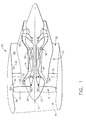
- FIG. 1 is a cross-sectional schematic illustration of an exemplary gas turbine engine assembly 10 having a longitudinal axis 11.
- Gas turbine engine assembly 10 includes a fan assembly 12 and a core gas turbine engine 13.
- Core gas turbine engine 13 includes a high pressure compressor 14, a combustor 16, and a high pressure turbine 18.
- gas turbine engine assembly 10 also includes a low pressure turbine 20, and a multi-stage booster compressor 32, and a splitter 34 that substantially circumscribes booster 32.
- Fan assembly 12 includes an array of fan blades 24 extending radially outward from a rotor disk 26, the forward portion of which is enclosed by a streamlined spinner 25.
- Gas turbine engine assembly 10 has an intake side 28 and an exhaust side 30.
- Fan assembly 12, booster 22, and turbine 20 are coupled together by a first rotor shaft and compressor 14 and turbine 18 are coupled together by a second rotor shaft 22.
- the compressed air that is discharged from booster 32 is channeled through compressor 14 wherein the airflow is further compressed and delivered to combustor 16.
- Hot products of combustion (not shown in Figure 1 ) from combustor 16 are utilized to drive turbines 18 and 20, and turbine 20 is utilized to drive fan assembly 12 and booster 32 by way of shaft 21.
- Gas turbine engine assembly 10 is operable at a range of operating conditions between design operating conditions and off-design operating conditions.
- a second portion 52 of the airflow discharged from fan assembly 12 is channeled through a bypass duct 40 to bypass a portion of the airflow from fan assembly 12 around core gas turbine engine 13. More specifically, bypass duct 40 extends between a fan casing or shroud 36 and splitter 34. Accordingly, a first portion 50 of the airflow from fan assembly 12 is channeled through booster 32 and then into compressor 14 as described above, and a second portion 52 of the airflow from fan assembly 12 is channeled through bypass duct 40 to provide thrust for an aircraft, for example.
- Splitter 34 divides the incoming airflow into first and second portions 50 and 52, respectively.
- Gas turbine engine assembly 10 also includes a fan frame assembly 60 to provide structural support for fan assembly 12 and is also utilized to couple fan assembly 12 to core gas turbine engine 13.
- Fan frame assembly 60 includes a plurality of outlet guide vanes 70 that extend substantially radially between a radially outer mounting flange and a radially inner mounting flange and are circumferentially-spaced within bypass duct 40.
- Fan frame assembly 60 may also include a plurality of struts that are coupled between a radially outer mounting flange and a radially inner mounting flange.
- fan frame assembly 60 is fabricated in arcuate segments in which flanges are coupled to outlet guide vanes 70 and struts.
- outlet guide vanes and struts are coupled coaxially within bypass duct 40.
- outlet guide vanes 70 may be coupled downstream from struts within bypass duct 40.
- Fan frame assembly 60 is one of various frame and support assemblies of gas turbine engine assembly 10 that are used to facilitate maintaining an orientation of various components within gas turbine engine assembly 10. More specifically, such frame and support assemblies interconnect stationary components and provide rotor bearing supports. Fan frame assembly 60 is coupled downstream from fan assembly 12 within bypass duct 40 such that outlet guide vanes 70 and struts are circumferentially-spaced around the outlet of fan assembly 12 and extend across the airflow path discharged from fan assembly 12.
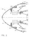
- FIG 2 is a partial cross-sectional elevational view of the forward portion of an exemplary aircraft gas turbine engine such as depicted in Figure 1 .
- a fairing 80 has been installed on the core gas turbine engine 13 in place of the spinner 25 and the fan blades 24 which have been removed and stored separately for transportation.
- the fairing 80 is of two-piece construction, comprising an inner portion 82 and an outer portion 84. Inner portion 82 and outer portion 84 are joined to one another as well as to the fan rotor 26 by bolts or other suitable fasteners 88 and suitably located mounting holes provided in the fairing components.
- Mounting holes 27 in the fan rotor 26, such as may typically be used to fasten the spinner 25 in place, may be utilized to secure the fairing 80 via fasteners 88.
- the fairing may be of one-piece (i.e., unitary) construction or multi-piece (i.e., two or more pieces) construction.
- the fairing 80 has a generally streamlined shape, typically of rounded conical or bullet-shaped design, to minimize drag on the engine during transport.
- the elements of the fairing are sized, shaped, and adapted to suit the characteristics of the particular engine application desired.
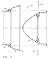
- Figure 3 is a cross-sectional elevational view of the fairing 80, similar to the view of Figure 2 but showing the fairing 80 in a disassembled condition and depicting the relationship of inner and outer portions 82 and 84, respectively.
- the outer portion 84 is of annular configuration and surrounds and is secured to the inner portion 82.
- an annular seal 86 which may be formed from rubber, foam, plastic, or other conformable material, which abuts and forms a substantially if not fully airtight seal against splitter 34 when the fairing 80 is installed on the core gas turbine engine 13.
- the annular seal 86 is integrally formed with the fairing 80, such as wherein the fairing 80 is formed from a material which is suitably compliant so as to conform to and sealingly engage the splitter 34.
- the fairing 80 is installed after removing and separately storing the spinner 25 and fan blades 24.
- the inner portion 82 of the fairing 80 is installed on the fan rotor 26 via mounting holes 27 and a plurality of fasteners 88.
- the outer portion of the fairing 84 is then installed over and around the inner portion 82 and is fastened to the inner portion 82 via fasteners 88.
- outer portion 84 moves axially toward the core gas turbine engine and the annular seal 86 comes into contact with and sealingly engages the forward portion of the splitter 34, so as to seal the opening of the booster 32 and prevent introduction of moisture, contaminants, and airflow into the booster 32 and thus into the core gas turbine engine 13.
- the process of securing the fairing 80 to the core gas turbine engine is a two phase operation wherein the first portion is secured first, followed by the second portion.
- the fairing 80 prevents air from flowing through the booster 32 during flight and imparting any rotational forces to the booster 32 (and any other rotating turbomachinery or accessories which share shaft 21 with booster 32). Air is also prevented from flowing through the compressor 14, as well as through both high pressure turbine 18 and low pressure turbine 20, and thereby avoiding imparting any rotational forces to those components (and any other rotating turbomachinery or accessories connected to shafts 21 or 22).
- the sealing engagement of the fairing 80 with the splitter 34 coupled with the mechanical engagement of the fairing 80 with the fan rotor 26 provides mechanical resistance to rotation for fan rotor 26 and any other components within the core gas turbine engine 13 which are associated with the shaft 21 to which the fan rotor 26 is attached.
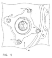
- Borescope motoring pad 90 is a location where a coverplate 92 can be removed via fasteners 94 (such as bolts, pins, screws, or other fasteners) to expose a socket 96 which is adapted for engagement by a tool (such as a 1 ⁇ 2 inch square drive ratchet, wrench, or bar) or a motorized drive assembly to rotate the core gas turbine engine 13 through a suitable gearbox assembly.
- a tool such as a 1 ⁇ 2 inch square drive ratchet, wrench, or bar
- a motorized drive assembly to rotate the core gas turbine engine 13 through a suitable gearbox assembly.
- a rotor lock 91 of suitable configuration for the particular engine application may be utilized.
- a rotor lock has suitable mounting holes 93, a seal 95, and a knob 97 of suitable configuration to engage the socket 96.
- the rotor lock 91 may be installed on the borescope motoring pad 90, engaging the socket 96 and sealing the opening via seal 95, and secured in place via fasteners 94, thereby mechanically preventing rotation of the socket 96 and all other rotating parts mechanically coupled to the socket 96.
- Rotor locks such as rotor lock 90 may be fabricated of any suitable material, such as metallic or composite materials, having suitable strength to resist turning motion of the socket 96.
- the fairing 80 may be a fiberglass material, a graphite material, a carbon material, a ceramic material, an aromatic polyamid material such as KEVLAR, a thin metallic material such as, but not limited to, titanium, aluminum, and/or a Metal Matrix Composite (MMC) material, and/or mixtures thereof.
- Any suitable thermosetting polymeric resin can be used in forming fairing 80, for example, vinyl ester resin, polyester resins, acrylic resins, epoxy resins, polyurethane resins, bismalimide resin, and mixtures thereof.
- the material is selected such that an exterior surface of fairing 80 is resistant to wear and or damage that may be caused by foreign objects ingested into gas turbine engine assembly 10. Alternate fairing configurations may use a thin metal wrap over a composite fairing to protect against such wear or damage.
Landscapes
- Engineering & Computer Science (AREA)
- Chemical & Material Sciences (AREA)
- Combustion & Propulsion (AREA)
- Mechanical Engineering (AREA)
- General Engineering & Computer Science (AREA)
- Transportation (AREA)
- Aviation & Aerospace Engineering (AREA)
- Manufacturing & Machinery (AREA)
- Structures Of Non-Positive Displacement Pumps (AREA)
- Turbine Rotor Nozzle Sealing (AREA)
Description
- The technology described herein relates generally to gas turbine engines, and more particularly, to a fairing kit for transporting such engines on ferry flights.
- At least one known gas turbine engine assembly includes a fan assembly that is mounted upstream from a core gas turbine engine. During operation, a portion of the airflow discharged from the fan assembly is channeled downstream to the core gas turbine engine wherein the airflow is further compressed. The compressed airflow is then channeled into a combustor, mixed with fuel, and ignited to generate hot combustion gases. The combustion gases are then channeled to a turbine, which extracts energy from the combustion gases for powering the compressor, as well as producing useful work to propel an aircraft in flight. The other portion of the airflow discharged from the fan assembly exits the engine through a fan stream nozzle.
- Gas turbine engines such as described herein are frequently installed on aircraft in pairs or multiples, such that in the course of normal operation the aircraft is propelled in flight by two, three, four, or more gas turbine engines. With such multi-engine installations, the aircraft may in some circumstances be safely operated with fewer than all installed engines operating.
- In service, gas turbine engines are subject to ordinary wear and tear, as well as instances wherein the engine itself may experience unusual wear and tear due to external or internal causes which make continued operation of the engine impossible or inadvisable. Engines which are in need of service or repair to return to satisfactory operating condition frequently must be transported to a suitable service or repair facility, which may be located some distance from where the engine was taken out of service. To transport the engine, therefore, steps must be taken to remove the engine from the aircraft on which it is installed for transportation as cargo or it must be transported by the aircraft while still in its installed location.
- Some aircraft have been configured specifically to carry a non-operating gas turbine engine to transport the engine from one location to another, such as to a location where it is needed for operation or to a service or repair facility to be returned to service. A special fixed or removable mounting pylon may be provided for this purpose. A known system for transporting an engine is described
US 4209149 . Other aircraft may be configured so as to be able to transport a non-operating gas turbine engine in a conventional mounting location. - When a non-operating aircraft gas turbine engine is carried aloft in an exposed position on the exterior of an aircraft (as opposed to being carried internally as cargo in a transport container), it is exposed to temperature and humidity changes as well as precipitation, dirt, debris, and other contaminants which may reach the core portion of the engine. Due to the possibility of moisture being present in the core portion of the engine after such a journey, a lengthy heating and drying process is normally required before the engine can be serviced or operated.
- Additionally, the non-operating aircraft gas turbine engine may have internal parts, particularly in the core portion of the engine, which have been subject to wear, damage, or contamination such that free rotation (or windmilling) of the engine due to airflow experienced during a non-operating transport operation may cause further wear and/or damage to such parts.
- Accordingly, there remains a need for a method for preparing and transporting non-operating aircraft gas turbine engines which limits exposure, to moisture and contamination, and free rotation, from transporting externally on an aircraft.
- In one aspect according to the present invention, a fairing kit for a gas turbine engine is described. The engine has a core gas turbine engine, a fan rotor, and a plurality of external fan blades attached to the fan rotor and powered by the core gas turbine engine. The core gas turbine engine has an annular splitter for directing a portion of incoming airflow into the core gas turbine engine. The fairing kit comprises: a) a fairing; b) a plurality of fasteners for securing the fairing to the core gas turbine engine; and c) a conformable seal for sealing mating surfaces of the fairing and the core gas turbine engine.
- Various aspects and embodiments of the present invention will now be described in connection with the accompanying drawings, in which:
-
Figure 1 is a cross-sectional illustration of an exemplary gas turbine engine assembly; -
Figure 2 is a partial cross-sectional elevational view of an exemplary gas turbine engine, illustrating an exemplary embodiment of a fairing installed on the engine; -
Figure 3 is a cross-sectional view of the fairing ofFigure 2 in a disassembled condition; -
Figure 4 is a partial view of the exemplary gas turbine engine ofFigure 1 illustrating an exemplary borescope motoring pad with a coverplate installed; -
Figure 5 is a partial view of the borescope motoring pad ofFigure 4 with the coverplate removed; and -
Figure 6 is a perspective view of an exemplary locking plate suitable for use with the borescope motoring pad ofFigures 4 and5 . -
Figure 1 is a cross-sectional schematic illustration of an exemplary gasturbine engine assembly 10 having alongitudinal axis 11. Gasturbine engine assembly 10 includes afan assembly 12 and a coregas turbine engine 13. Coregas turbine engine 13 includes a high pressure compressor 14, acombustor 16, and ahigh pressure turbine 18. In the exemplary embodiment, gasturbine engine assembly 10 also includes alow pressure turbine 20, and amulti-stage booster compressor 32, and asplitter 34 that substantially circumscribesbooster 32. -
Fan assembly 12 includes an array offan blades 24 extending radially outward from arotor disk 26, the forward portion of which is enclosed by astreamlined spinner 25. Gasturbine engine assembly 10 has anintake side 28 and anexhaust side 30.Fan assembly 12,booster 22, andturbine 20 are coupled together by a first rotor shaft and compressor 14 andturbine 18 are coupled together by asecond rotor shaft 22. - In operation, air flows through
fan assembly 12 and afirst portion 50 of the airflow is channeled throughbooster 32. The compressed air that is discharged frombooster 32 is channeled through compressor 14 wherein the airflow is further compressed and delivered tocombustor 16. Hot products of combustion (not shown inFigure 1 ) fromcombustor 16 are utilized to driveturbines turbine 20 is utilized to drivefan assembly 12 andbooster 32 by way ofshaft 21. Gasturbine engine assembly 10 is operable at a range of operating conditions between design operating conditions and off-design operating conditions. - A
second portion 52 of the airflow discharged fromfan assembly 12 is channeled through abypass duct 40 to bypass a portion of the airflow fromfan assembly 12 around coregas turbine engine 13. More specifically,bypass duct 40 extends between a fan casing orshroud 36 andsplitter 34. Accordingly, afirst portion 50 of the airflow fromfan assembly 12 is channeled throughbooster 32 and then into compressor 14 as described above, and asecond portion 52 of the airflow fromfan assembly 12 is channeled throughbypass duct 40 to provide thrust for an aircraft, for example.Splitter 34 divides the incoming airflow into first andsecond portions turbine engine assembly 10 also includes afan frame assembly 60 to provide structural support forfan assembly 12 and is also utilized tocouple fan assembly 12 to coregas turbine engine 13. -
Fan frame assembly 60 includes a plurality ofoutlet guide vanes 70 that extend substantially radially between a radially outer mounting flange and a radially inner mounting flange and are circumferentially-spaced withinbypass duct 40.Fan frame assembly 60 may also include a plurality of struts that are coupled between a radially outer mounting flange and a radially inner mounting flange. In one embodiment,fan frame assembly 60 is fabricated in arcuate segments in which flanges are coupled tooutlet guide vanes 70 and struts. In one embodiment, outlet guide vanes and struts are coupled coaxially withinbypass duct 40. Optionally, outlet guide vanes 70 may be coupled downstream from struts withinbypass duct 40. -
Fan frame assembly 60 is one of various frame and support assemblies of gasturbine engine assembly 10 that are used to facilitate maintaining an orientation of various components within gasturbine engine assembly 10. More specifically, such frame and support assemblies interconnect stationary components and provide rotor bearing supports.Fan frame assembly 60 is coupled downstream fromfan assembly 12 withinbypass duct 40 such that outlet guide vanes 70 and struts are circumferentially-spaced around the outlet offan assembly 12 and extend across the airflow path discharged fromfan assembly 12. -
Figure 2 is a partial cross-sectional elevational view of the forward portion of an exemplary aircraft gas turbine engine such as depicted inFigure 1 . As shown inFigure 2 , afairing 80 has been installed on the coregas turbine engine 13 in place of thespinner 25 and thefan blades 24 which have been removed and stored separately for transportation. In the embodiment shown inFigure 2 , thefairing 80 is of two-piece construction, comprising aninner portion 82 and anouter portion 84.Inner portion 82 andouter portion 84 are joined to one another as well as to thefan rotor 26 by bolts or othersuitable fasteners 88 and suitably located mounting holes provided in the fairing components. Mountingholes 27 in thefan rotor 26, such as may typically be used to fasten thespinner 25 in place, may be utilized to secure thefairing 80 viafasteners 88. - Depending upon the physical configuration of the gas turbine engine upon which the
fairing 80 is to be installed, the fairing may be of one-piece (i.e., unitary) construction or multi-piece (i.e., two or more pieces) construction. Thefairing 80 has a generally streamlined shape, typically of rounded conical or bullet-shaped design, to minimize drag on the engine during transport. The elements of the fairing are sized, shaped, and adapted to suit the characteristics of the particular engine application desired. -
Figure 3 is a cross-sectional elevational view of thefairing 80, similar to the view ofFigure 2 but showing thefairing 80 in a disassembled condition and depicting the relationship of inner andouter portions outer portion 84 is of annular configuration and surrounds and is secured to theinner portion 82. Also shown inFigure 3 is anannular seal 86, which may be formed from rubber, foam, plastic, or other conformable material, which abuts and forms a substantially if not fully airtight seal againstsplitter 34 when thefairing 80 is installed on the coregas turbine engine 13. Other configurations may be possible wherein theannular seal 86 is integrally formed with the fairing 80, such as wherein the fairing 80 is formed from a material which is suitably compliant so as to conform to and sealingly engage thesplitter 34. - For the embodiment shown in
Figures 2 and3 , the fairing 80 is installed after removing and separately storing thespinner 25 andfan blades 24. Theinner portion 82 of the fairing 80 is installed on thefan rotor 26 via mountingholes 27 and a plurality offasteners 88. The outer portion of the fairing 84 is then installed over and around theinner portion 82 and is fastened to theinner portion 82 viafasteners 88. As theouter portion 84 is secured in position,outer portion 84 moves axially toward the core gas turbine engine and theannular seal 86 comes into contact with and sealingly engages the forward portion of thesplitter 34, so as to seal the opening of thebooster 32 and prevent introduction of moisture, contaminants, and airflow into thebooster 32 and thus into the coregas turbine engine 13. As such, for the embodiment shown the process of securing the fairing 80 to the core gas turbine engine is a two phase operation wherein the first portion is secured first, followed by the second portion. - By effectively sealing the front of the
booster 32, the fairing 80 prevents air from flowing through thebooster 32 during flight and imparting any rotational forces to the booster 32 (and any other rotating turbomachinery or accessories which shareshaft 21 with booster 32). Air is also prevented from flowing through the compressor 14, as well as through bothhigh pressure turbine 18 andlow pressure turbine 20, and thereby avoiding imparting any rotational forces to those components (and any other rotating turbomachinery or accessories connected toshafts 21 or 22). - Additionally, the sealing engagement of the fairing 80 with the
splitter 34 coupled with the mechanical engagement of the fairing 80 with the fan rotor 26 (via fasteners 88) provides mechanical resistance to rotation forfan rotor 26 and any other components within the coregas turbine engine 13 which are associated with theshaft 21 to which thefan rotor 26 is attached. - Many aircraft gas turbine engines have a location where a device can be attached to rotate the core
gas turbine engine 13 for inspection and/or service operations, such as borescope inspection. This location (shown inFigures 4 and5 ) is commonly referred to as a borescope motoring or turningpad 90.Borescope motoring pad 90 is a location where acoverplate 92 can be removed via fasteners 94 (such as bolts, pins, screws, or other fasteners) to expose asocket 96 which is adapted for engagement by a tool (such as a ½ inch square drive ratchet, wrench, or bar) or a motorized drive assembly to rotate the coregas turbine engine 13 through a suitable gearbox assembly. - To provide additional optional mechanical security against rotation of the core
gas turbine engine 13 during a transport operation, arotor lock 91 of suitable configuration for the particular engine application may be utilized. Such a rotor lock has suitable mountingholes 93, aseal 95, and aknob 97 of suitable configuration to engage thesocket 96. Therotor lock 91 may be installed on theborescope motoring pad 90, engaging thesocket 96 and sealing the opening viaseal 95, and secured in place viafasteners 94, thereby mechanically preventing rotation of thesocket 96 and all other rotating parts mechanically coupled to thesocket 96. Rotor locks such asrotor lock 90 may be fabricated of any suitable material, such as metallic or composite materials, having suitable strength to resist turning motion of thesocket 96. - In the exemplary embodiment, the fairing 80 may be a fiberglass material, a graphite material, a carbon material, a ceramic material, an aromatic polyamid material such as KEVLAR, a thin metallic material such as, but not limited to, titanium, aluminum, and/or a Metal Matrix Composite (MMC) material, and/or mixtures thereof. Any suitable thermosetting polymeric resin can be used in forming
fairing 80, for example, vinyl ester resin, polyester resins, acrylic resins, epoxy resins, polyurethane resins, bismalimide resin, and mixtures thereof. Overall, the material is selected such that an exterior surface of fairing 80 is resistant to wear and or damage that may be caused by foreign objects ingested into gasturbine engine assembly 10. Alternate fairing configurations may use a thin metal wrap over a composite fairing to protect against such wear or damage. - This written description uses examples to disclose the invention, including the preferred mode, and also to enable any person skilled in the art to make and use the invention. The patentable scope of the invention is defined by the claims, and may include other examples that occur to those skilled in the art. Such other examples are intended to be within the scope of the claims if they have structural elements that do not differ from the literal language of the claims, or if they include equivalent structural elements with insubstantial differences from the literal languages of the claims.
Claims (9)
- A fairing kit for use with a gas turbine engine, said engine having a core gas turbine engine (13), a fan rotor (26), and a plurality of external fan blades (24) attached to said fan rotor (26) and powered by said core gas turbine engine (13), said core gas turbine engine (13) having an annular splitter (34) for directing a portion of incoming airflow into said core gas turbine engine (13), said fairing kit comprising:a fairing (80); anda plurality of fasteners (88) to secure said fairing (80) to said core gas turbine engine (13); characterised in thata conformable seal (86) is provided to seal mating surfaces of said fairing (80) and said core gas turbine engine (13), and said fairing (80) includes a first portion (82) for securement to said fan rotor (26) and an annular second portion (84) which surrounds and is secured to said first portion (82).
- The fairing kit of claim 1, wherein said fairing (80) has a streamlined shape.
- The fairing kit of any preceding claim, wherein said fairing (80) is of multi-piece construction.
- The fairing kit of any preceding claim, wherein said fairing (80) is capable of being secured to said splitter (34).
- The fairing kit of any preceding claim, wherein said fairing (80) is capable of being secured to a fan rotor (26).
- The fairing kit of any preceding claim, wherein said fairing is capable of sealing and preventing airflow through said core gas turbine engine (13).
- The fairing kit of any of the preceding claims, wherein said second portion (84) is capable of being sealingly engaged to said splitter (34) when secured to said first portion (82).
- The fairing kit of any of the preceding claims, wherein said fairing (80) is configured so as to be capable of providing mechanical resistance to rotation of components within said core gas turbine engine (13).
- The fairing kit of any of the preceding claims, wherein said fairing kit further includes a rotor lock (91) capable of preventing rotation of components within said core gas turbine engine (13).
Applications Claiming Priority (1)
| Application Number | Priority Date | Filing Date | Title |
|---|---|---|---|
| US11/966,165 US20100047077A1 (en) | 2007-12-28 | 2007-12-28 | Ferry Flight Engine Fairing Kit |
Publications (3)
| Publication Number | Publication Date |
|---|---|
| EP2075436A2 EP2075436A2 (en) | 2009-07-01 |
| EP2075436A3 EP2075436A3 (en) | 2009-07-08 |
| EP2075436B1 true EP2075436B1 (en) | 2012-08-08 |
Family
ID=40278779
Family Applications (1)
| Application Number | Title | Priority Date | Filing Date |
|---|---|---|---|
| EP08172249A Expired - Fee Related EP2075436B1 (en) | 2007-12-28 | 2008-12-19 | Ferry flight engine fairing kit |
Country Status (4)
| Country | Link |
|---|---|
| US (1) | US20100047077A1 (en) |
| EP (1) | EP2075436B1 (en) |
| JP (1) | JP2009185804A (en) |
| CA (1) | CA2647753A1 (en) |
Families Citing this family (11)
| Publication number | Priority date | Publication date | Assignee | Title |
|---|---|---|---|---|
| US20100043228A1 (en) * | 2007-12-28 | 2010-02-25 | James Lloyd Daniels | Method of Preparing an Engine for Ferry Flight |
| US8814512B2 (en) * | 2011-07-05 | 2014-08-26 | United Technologies Corporation | Fan disk apparatus and method |
| JP5863321B2 (en) * | 2011-08-08 | 2016-02-16 | 三菱重工コンプレッサ株式会社 | Rotating machine jig and method of transporting rotating machine |
| US9759129B2 (en) | 2012-12-28 | 2017-09-12 | United Technologies Corporation | Removable nosecone for a gas turbine engine |
| US9540939B2 (en) * | 2012-12-28 | 2017-01-10 | United Technologies Corporation | Gas turbine engine with attached nosecone |
| US9206742B2 (en) * | 2012-12-29 | 2015-12-08 | United Technologies Corporation | Passages to facilitate a secondary flow between components |
| EP2971568B1 (en) * | 2013-03-15 | 2021-11-03 | Raytheon Technologies Corporation | Flap seal for a fan of a gas turbine engine |
| CN103216360B (en) * | 2013-04-07 | 2016-03-02 | 朱晓义 | Turbogenerator and power plant |
| EP3052788B8 (en) | 2013-10-02 | 2021-04-07 | Raytheon Technologies Corporation | Recirculation seal for use in a gas turbine engine |
| US10267177B2 (en) * | 2015-02-09 | 2019-04-23 | Rolls-Royce North American Technologies Inc. | Turbine assembly having a rotor system lock |
| CN109250149B (en) * | 2018-09-26 | 2023-09-19 | 中国空气动力研究与发展中心超高速空气动力研究所 | Wind tunnel test device for separation simulation of air suction type hypersonic vehicle fairing |
Family Cites Families (17)
| Publication number | Priority date | Publication date | Assignee | Title |
|---|---|---|---|---|
| US3000533A (en) * | 1959-04-24 | 1961-09-19 | William E Rockhill | Engine inlet plug |
| US3646980A (en) * | 1970-06-15 | 1972-03-07 | Peterson Products Of San Mateo | Jet engine cowl cover |
| US3871844A (en) * | 1973-09-28 | 1975-03-18 | Sr Frank F Calvin | Screen apparatus for air inlet |
| US3990814A (en) * | 1975-06-25 | 1976-11-09 | United Technologies Corporation | Spinner |
| GB1557856A (en) * | 1977-04-20 | 1979-12-12 | Rolls Royce | Spinner or nose bullet |
| GB1594354A (en) * | 1977-06-02 | 1981-07-30 | Rolls Royce | Device for turning the rotor of a gas turbine engine |
| US4209149A (en) * | 1977-12-27 | 1980-06-24 | Boeing Commercial Airplane Company | Contracted inlet for jet engine being transported as cargo |
| US4314681A (en) * | 1979-08-31 | 1982-02-09 | General Electric Company | Drag-reducing component |
| CA2021087A1 (en) * | 1989-09-07 | 1991-03-08 | Eugene J. Antuna | Ultra high bypass engine integrated fan/cowl and transportation/removal |
| US5224341A (en) * | 1992-01-06 | 1993-07-06 | United Technologies Corporation | Separable fan strut for a gas turbofan powerplant |
| US5833435A (en) * | 1996-12-24 | 1998-11-10 | United Technologies Corporation | Inlet nose cone assembly and method for repairing the assembly |
| FR2851787B1 (en) * | 2003-02-28 | 2005-05-20 | Airbus France | DEVICE FOR PROTECTING AN AIR INTAKE STRUCTURE OF A REACTION ENGINE |
| US6887043B2 (en) * | 2003-03-28 | 2005-05-03 | General Electric Company | Methods and apparatus for assembling gas turbine engines |
| US6905309B2 (en) * | 2003-08-28 | 2005-06-14 | General Electric Company | Methods and apparatus for reducing vibrations induced to compressor airfoils |
| FR2866068B1 (en) * | 2004-02-06 | 2006-07-07 | Snecma Moteurs | SOLIDARITY BLOWER TURBOREACTOR OF A DRIVE SHAFT SUPPORTED BY A FIRST AND A SECOND BEARING |
| US7721526B2 (en) * | 2006-06-28 | 2010-05-25 | Ishikawajima-Harima Heavy Industries Co., Ltd. | Turbofan engine |
| US20100043228A1 (en) * | 2007-12-28 | 2010-02-25 | James Lloyd Daniels | Method of Preparing an Engine for Ferry Flight |
-
2007
- 2007-12-28 US US11/966,165 patent/US20100047077A1/en not_active Abandoned
-
2008
- 2008-12-19 EP EP08172249A patent/EP2075436B1/en not_active Expired - Fee Related
- 2008-12-22 JP JP2008324863A patent/JP2009185804A/en active Pending
- 2008-12-23 CA CA002647753A patent/CA2647753A1/en not_active Abandoned
Also Published As
| Publication number | Publication date |
|---|---|
| EP2075436A3 (en) | 2009-07-08 |
| EP2075436A2 (en) | 2009-07-01 |
| US20100047077A1 (en) | 2010-02-25 |
| CA2647753A1 (en) | 2009-06-28 |
| JP2009185804A (en) | 2009-08-20 |
Similar Documents
| Publication | Publication Date | Title |
|---|---|---|
| EP2075436B1 (en) | Ferry flight engine fairing kit | |
| EP3415437B1 (en) | Aft fan counter-rotating turbine engine | |
| US20080159856A1 (en) | Guide vane and method of fabricating the same | |
| US20080072571A1 (en) | Aeroengine thrust reverser | |
| US20140252160A1 (en) | Reverse flow gas turbine engine removable core | |
| US20080072569A1 (en) | Guide vane and method of fabricating the same | |
| US20080159851A1 (en) | Guide Vane and Method of Fabricating the Same | |
| GB2536796A (en) | Unducted fan for an aircraft turbine engine | |
| CN110341969B (en) | Latch device for fan cowling of fuselage-mounted power plant | |
| US11421592B2 (en) | Gas turbine engine | |
| US11548652B2 (en) | Nacelle | |
| EP2075420B1 (en) | Method of preparing an engine for transportation | |
| CN106870165B (en) | Gas turbine engine | |
| US10767566B2 (en) | Electric propulsion motor cooling system and method | |
| CN104684804A (en) | Propeller comprising a movable dynamic scoop | |
| US20210396147A1 (en) | Electric module for an aircraft fan comprising blades with improved attachment | |
| US10385868B2 (en) | Strut assembly for an aircraft engine | |
| US20150308381A1 (en) | Drag link assembly including buried drag link fitting | |
| EP3647562B1 (en) | Method of replacing a module | |
| US10578027B1 (en) | Combustor blade and vane spacing for ice crystal protection for a gas turbine engine | |
| US20200056541A1 (en) | Fan blade removal method and tooling | |
| US20190382122A1 (en) | Gas turbine engine | |
| EP3434596B1 (en) | Nacelle |
Legal Events
| Date | Code | Title | Description |
|---|---|---|---|
| PUAI | Public reference made under article 153(3) epc to a published international application that has entered the european phase |
Free format text: ORIGINAL CODE: 0009012 |
|
| PUAL | Search report despatched |
Free format text: ORIGINAL CODE: 0009013 |
|
| AK | Designated contracting states |
Kind code of ref document: A2 Designated state(s): AT BE BG CH CY CZ DE DK EE ES FI FR GB GR HR HU IE IS IT LI LT LU LV MC MT NL NO PL PT RO SE SI SK TR |
|
| AX | Request for extension of the european patent |
Extension state: AL BA MK RS |
|
| AK | Designated contracting states |
Kind code of ref document: A3 Designated state(s): AT BE BG CH CY CZ DE DK EE ES FI FR GB GR HR HU IE IS IT LI LT LU LV MC MT NL NO PL PT RO SE SI SK TR |
|
| AX | Request for extension of the european patent |
Extension state: AL BA MK RS |
|
| 17P | Request for examination filed |
Effective date: 20100108 |
|
| AKX | Designation fees paid |
Designated state(s): DE FR GB |
|
| 17Q | First examination report despatched |
Effective date: 20100311 |
|
| REG | Reference to a national code |
Ref country code: DE Ref legal event code: R079 Ref document number: 602008017766 Country of ref document: DE Free format text: PREVIOUS MAIN CLASS: F02C0007040000 Ipc: F02C0007000000 |
|
| RIC1 | Information provided on ipc code assigned before grant |
Ipc: F02C 7/20 20060101ALI20111214BHEP Ipc: F01D 25/28 20060101ALI20111214BHEP Ipc: B64F 1/00 20060101ALI20111214BHEP Ipc: B64F 5/00 20060101ALI20111214BHEP Ipc: F02K 3/00 20060101ALI20111214BHEP Ipc: F02C 7/00 20060101AFI20111214BHEP |
|
| GRAP | Despatch of communication of intention to grant a patent |
Free format text: ORIGINAL CODE: EPIDOSNIGR1 |
|
| GRAS | Grant fee paid |
Free format text: ORIGINAL CODE: EPIDOSNIGR3 |
|
| GRAA | (expected) grant |
Free format text: ORIGINAL CODE: 0009210 |
|
| AK | Designated contracting states |
Kind code of ref document: B1 Designated state(s): DE FR GB |
|
| REG | Reference to a national code |
Ref country code: GB Ref legal event code: FG4D |
|
| REG | Reference to a national code |
Ref country code: DE Ref legal event code: R096 Ref document number: 602008017766 Country of ref document: DE Effective date: 20120927 |
|
| PLBE | No opposition filed within time limit |
Free format text: ORIGINAL CODE: 0009261 |
|
| STAA | Information on the status of an ep patent application or granted ep patent |
Free format text: STATUS: NO OPPOSITION FILED WITHIN TIME LIMIT |
|
| REG | Reference to a national code |
Ref country code: DE Ref legal event code: R119 Ref document number: 602008017766 Country of ref document: DE |
|
| 26N | No opposition filed |
Effective date: 20130510 |
|
| GBPC | Gb: european patent ceased through non-payment of renewal fee |
Effective date: 20121219 |
|
| REG | Reference to a national code |
Ref country code: DE Ref legal event code: R097 Ref document number: 602008017766 Country of ref document: DE Effective date: 20130510 |
|
| REG | Reference to a national code |
Ref country code: FR Ref legal event code: ST Effective date: 20130830 |
|
| PG25 | Lapsed in a contracting state [announced via postgrant information from national office to epo] |
Ref country code: DE Free format text: LAPSE BECAUSE OF NON-PAYMENT OF DUE FEES Effective date: 20130702 |
|
| REG | Reference to a national code |
Ref country code: DE Ref legal event code: R119 Ref document number: 602008017766 Country of ref document: DE Effective date: 20130702 |
|
| PG25 | Lapsed in a contracting state [announced via postgrant information from national office to epo] |
Ref country code: GB Free format text: LAPSE BECAUSE OF NON-PAYMENT OF DUE FEES Effective date: 20121219 Ref country code: FR Free format text: LAPSE BECAUSE OF NON-PAYMENT OF DUE FEES Effective date: 20130102 |