EP2075201A1 - Heat-shrinkable packaging - Google Patents
Heat-shrinkable packaging Download PDFInfo
- Publication number
- EP2075201A1 EP2075201A1 EP09158040A EP09158040A EP2075201A1 EP 2075201 A1 EP2075201 A1 EP 2075201A1 EP 09158040 A EP09158040 A EP 09158040A EP 09158040 A EP09158040 A EP 09158040A EP 2075201 A1 EP2075201 A1 EP 2075201A1
- Authority
- EP
- European Patent Office
- Prior art keywords
- seal
- film
- heat
- receptacle
- bag
- Prior art date
- Legal status (The legal status is an assumption and is not a legal conclusion. Google has not performed a legal analysis and makes no representation as to the accuracy of the status listed.)
- Granted
Links
Images


Classifications
-
- B—PERFORMING OPERATIONS; TRANSPORTING
- B65—CONVEYING; PACKING; STORING; HANDLING THIN OR FILAMENTARY MATERIAL
- B65D—CONTAINERS FOR STORAGE OR TRANSPORT OF ARTICLES OR MATERIALS, e.g. BAGS, BARRELS, BOTTLES, BOXES, CANS, CARTONS, CRATES, DRUMS, JARS, TANKS, HOPPERS, FORWARDING CONTAINERS; ACCESSORIES, CLOSURES, OR FITTINGS THEREFOR; PACKAGING ELEMENTS; PACKAGES
- B65D75/00—Packages comprising articles or materials partially or wholly enclosed in strips, sheets, blanks, tubes, or webs of flexible sheet material, e.g. in folded wrappers
- B65D75/002—Packages comprising articles or materials partially or wholly enclosed in strips, sheets, blanks, tubes, or webs of flexible sheet material, e.g. in folded wrappers in shrink films
-
- Y—GENERAL TAGGING OF NEW TECHNOLOGICAL DEVELOPMENTS; GENERAL TAGGING OF CROSS-SECTIONAL TECHNOLOGIES SPANNING OVER SEVERAL SECTIONS OF THE IPC; TECHNICAL SUBJECTS COVERED BY FORMER USPC CROSS-REFERENCE ART COLLECTIONS [XRACs] AND DIGESTS
- Y10—TECHNICAL SUBJECTS COVERED BY FORMER USPC
- Y10T—TECHNICAL SUBJECTS COVERED BY FORMER US CLASSIFICATION
- Y10T428/00—Stock material or miscellaneous articles
- Y10T428/13—Hollow or container type article [e.g., tube, vase, etc.]
- Y10T428/1328—Shrinkable or shrunk [e.g., due to heat, solvent, volatile agent, restraint removal, etc.]
-
- Y—GENERAL TAGGING OF NEW TECHNOLOGICAL DEVELOPMENTS; GENERAL TAGGING OF CROSS-SECTIONAL TECHNOLOGIES SPANNING OVER SEVERAL SECTIONS OF THE IPC; TECHNICAL SUBJECTS COVERED BY FORMER USPC CROSS-REFERENCE ART COLLECTIONS [XRACs] AND DIGESTS
- Y10—TECHNICAL SUBJECTS COVERED BY FORMER USPC
- Y10T—TECHNICAL SUBJECTS COVERED BY FORMER US CLASSIFICATION
- Y10T428/00—Stock material or miscellaneous articles
- Y10T428/13—Hollow or container type article [e.g., tube, vase, etc.]
- Y10T428/1334—Nonself-supporting tubular film or bag [e.g., pouch, envelope, packet, etc.]
- Y10T428/1341—Contains vapor or gas barrier, polymer derived from vinyl chloride or vinylidene chloride, or polymer containing a vinyl alcohol unit
-
- Y—GENERAL TAGGING OF NEW TECHNOLOGICAL DEVELOPMENTS; GENERAL TAGGING OF CROSS-SECTIONAL TECHNOLOGIES SPANNING OVER SEVERAL SECTIONS OF THE IPC; TECHNICAL SUBJECTS COVERED BY FORMER USPC CROSS-REFERENCE ART COLLECTIONS [XRACs] AND DIGESTS
- Y10—TECHNICAL SUBJECTS COVERED BY FORMER USPC
- Y10T—TECHNICAL SUBJECTS COVERED BY FORMER US CLASSIFICATION
- Y10T428/00—Stock material or miscellaneous articles
- Y10T428/13—Hollow or container type article [e.g., tube, vase, etc.]
- Y10T428/1352—Polymer or resin containing [i.e., natural or synthetic]
- Y10T428/1379—Contains vapor or gas barrier, polymer derived from vinyl chloride or vinylidene chloride, or polymer containing a vinyl alcohol unit
- Y10T428/1383—Vapor or gas barrier, polymer derived from vinyl chloride or vinylidene chloride, or polymer containing a vinyl alcohol unit is sandwiched between layers [continuous layer]
Definitions
- FIGS. 3 and 4 A second embodiment of the heat-shrinkable packaging receptacle of the present invention is illustrated in FIGS. 3 and 4 generally as bag 110.
- the bag 110 is formed from a sheet of heat-shrinkable film 111 having a first edge 112, a second edge 114, a top surface 113 and a bottom surface 115.
- the bag 110 includes a first seal 116 bonding the first and second edges 112 and 114 in an abutting arrangement, or fin seal, thereby defining a tube member 118.
- the first and second edges 12 and 14 are brought together such that the bottom surface 115 of both the first and second edges 112 and 114 is placed in face-to-face contact and a seal, such as a heat seal, is provided therebetween.
- FIGS. 5 and 6 Another embodiment of the present invention is illustrated in FIGS. 5 and 6 generally as bag 210.
- Bag 210 is formed from a sheet of heat-shrinkable film 210 having a first edge 212, a second edges 214, an inner surface 213 and an outer surface 215.
- the bag 210 includes a first seal 216 comprising a butt-seal, that bonds the first and second edges 212 and 214 in a longitudinally abutting relationship with or without directly bonding surfaces of the first and second edges 212 and 214 together.
- the bag 210 includes a second seal 232 provided through the first and second bag walls 220 and 222 extending laterally across the bag 210 from the first bag edge 224 to the second bag edge 226, thereby closing the bag end 230 and defining a product receiving chamber 234.
- a center portion of the film may be corona treated, while those portions along each of the machine direction edges of the film are not. In this manner, those portions along each machine direction edge, that are sealed together to form the first seals 16 or 116 as described above, are not corona treated and should not be adversely affected.
- the length of the bags can easily be varied by changing the distance between cuts.
- the width of the bags can also be easily varied by changing the width of the film by slitting the standard rollstock.
- cuts and seals may be made alternately and apart from each other to form dual attached bags in saddle bag fashion.
- the film composition was produced generally utilizing the apparatus and method described in U.S. Pat. No. 3,456,044 (Pahlke ) which describes a coextrusion type of double bubble method and in further accordance with the detailed description above. All layers were extruded as a primary tube which was cooled upon exiting the die e.g. by spraying with tap water. This primary tube was then reheated by radiant heaters(although other means known to those skilled in the art, such as conduction or convection heating may be used) with further heating to the draw (orientation) temperature for biaxial orientation accomplished by an air cushion which was itself heated by transverse flow through a heated porous tube concentrically positioned around the moving primary tube. Cooling was accomplished by means of a concentric air ring. Draw point temperature, bubble heating and cooling rates and orientation ratios were generally adjusted to maximize bubble stability and throughput for the desired amount of stretching or orientation. All percentages are by weight unless indicated otherwise.
- Oxygen barrier materials which may be included in the films utilized for the inventive bags include ethylene vinyl alcohol copolymers (EVOH), polyacrylonitriles, polyamides and vinylidene chloride copolymers (PVDC).
- EVOH ethylene vinyl alcohol copolymers
- PVDC vinylidene chloride copolymers
- nylon may provide useful oxygen barrier properties especially at low temperatures, e.g., as used with frozen foods.
- Preferred oxygen barrier polymers for use with the present invention are vinylidene chloride copolymers or vinylidene chloride with various comonomers such as vinyl chloride (VC-VDC copolymer) or methyl acrylate (MA-VDC copolymer), as well as EVOH.
- peelable films and peelable sealing systems may be employed in the present invention.
- a film comprising a coextrusion of at least three layers (referred to as three layer peelable system to distinguish it from systems using one or more contaminated seal layers described below) having an outer layer, an inner heat seal layer and a tie layer disposed between the outer layer and the inner heat seal layer is used.
- the film layers are selected such that peeling occurs by breaking apart the tie layer and/or a bond between the tie layer and at least one of the outer and inner layers.
- the preferred three layer coextruded peeling structure described above contemplates optional additional layers to product a film of 4, 5, 6, 7, 8, 9, 10 or more layers. It is further contemplated that one or more additional layers may be coextruded with the described three layers or separately and that the multilayer film structure may be formed not only by coextrusion, but also by other methods well known in the art such as coating lamination, adhesive lamination or combinations thereof.
- each layer may be typically ⁇ 50% inner surface heat sealing layer 434; ⁇ 20% barrier layer 435; ⁇ 28% core layer 436; ⁇ 15% tie layer 437; and ⁇ 15% outer heat sealing layer 438.
- the first seal 416 is made by longitudinally heat sealing the inner film surface 419 of film 411 to the outer film surface 433 along their respective lengths, such that inner film surface 419 and outer film surface 433 overlap. In this manner, a fusion bond is made between the inner surface heat sealing layer 434 and the outer surface heat sealing layer 438.
- the peelable bond of the system is provided by the tie layer 437 and peeling occurs there, e .
- 11-13 combines (a) an end seal which mates like materials with strong seal properties to each other keeping distal the easily peelable tie layer 437 and (b) a lap seal having peelable tie layer 437 proximate the outer surface heat sealing layer 438 and lap seal interface 432 , thereby providing an easily peelable opening in bags or packages made using the described configuration.
- the pull flap 440 may be readily grasped by the end user and pulled to easily open the package, without resort to a cutting instrument, as is often required when opening packages without a peelable system. Although shown as extending the entire length of the bag 415a, a skilled artisan will appreciate that the pull flap 440 may be cut to a desired shape or that any other known device known to aid initiation of peeling may be incorporated.
- the preferred film illustrated in FIGS. 10 , 12 and 13 described previously is also preferred for use with bag 415a.
- the seal strip 741 includes a second margin 719 longitudinally heat sealed to the second side 430b by second heat seal 721, such that the inside surface 714 is sealed in face-to-face contact with the outer surface 433 of the second side 430b.
- a pull flap 440 may be provided by including a portion of the strip film 711 that extends outwardly beyond second heat seal 721 joining the second margin 719 and the second side 430b.
- the first side 430a could be provided with a portion that extends outwardly beyond the second heat seal 420.
- the strip film 711 may not include a peelable system while the film 411 does include a peelable system, or both film 411 and strip film 711 may include compatible peelable systems.
- the strip film 711 is preferably heat-shrinkable, but need not be.
- the films selected to fabricate the inventive receptacles are preferably biaxially stretched or oriented by the well-known trapped bubble or double bubble technique as for example described in U.S. Patent Nos. 3,456,044 and 6,511,688 whose descriptions and teachings are hereby incorporated by reference in their entireties.
- This technique an extruded primary tube leaving the tubular extrusion die is cooled, collapsed and then preferably oriented by reheating, reinflating to form a secondary bubble and recooling.
- the film is preferably biaxially oriented wherein transverse (TD) orientation is accomplished by inflation to radially expand the heated film.
- Machine direction (MD) orientation is preferably accomplished with the use of nip rolls rotating at different speeds to pull or draw the film tube in the machine direction.
- the stretch ratio in the biaxial orientation to form the bag material is preferably sufficient to provide a film with total thickness of between about 1 and 8 mils.
- the MD stretch ratio is typically 3:1-5:1 and the TD stretch ratio is also typically 3:1-5:1.
- a double bubble (also know as a trapped bubble) process is shown.
- the polymer blends making up the several layers are coextruded by conveying separate melt streams 611a, 611b, and 611c to the die 630. These polymer melts are joined together and coextruded from annular die 630 as a relatively thick walled multilayered tube 632.
- lap seal 416 having an additional overlap portion that will act as a pull flap, to form a continuous backseamed tube member 418.
- the second seal 420 is provided transversely across the tube member 418 at a desired location spaced from the opening 424.
- the tube member 418 is then (or preferably simultaneously) severed to separate the portion containing the second seal from the continuous tube, thereby forming bag 415.
- a transverse cut forming the mouth of the adjacent bag is being made.
- the ram puncture test is used to determine the maximum puncture load or force, and the maximum puncture stress of a flexible film when struck by a hemispherically or spherically shaped striker. This test provides a quantitative measure of the puncture resistance of thin plastic films. This test is further described in U.S. Patent Application No. 09/401,692 and the teachings of the '692 patent application are hereby incorporated by reference in their entirety.
- irradiation induced cross-linking and/or scission is preferred to irradiate the entire film to broaden the heat sealing range and/or enhance the toughness properties of the inner and outer layers by irradiation induced cross-linking and/or scission.
- This is preferably done by irradiation with an election beam at dosage level of at least about 2 megarads (MR) and preferably in the range of 3-5 MR, although higher dosages may be employed especially for thicker films or where the primary tube is irradiated. Irradiation may be done on the primary tube or after biaxial orientation. The latter, called post-irradiation, is preferred and described in Lustig et al. U.S. Pat. No. 4,737,391 , which is hereby incorporated by reference.
- An advantage of post-irradiation is that a relatively thin film is treated instead of the relatively thick primary tube, thereby reducing the power requirement for a given treatment level.
- Example 2 a fifth tie layer, e.g., comprising EMA; a sixth intermediate layer comprising a blend of 20-45% each of EVA ethylene-butene -1 copolymer and ethylene-octene -1 copolymer; and a seventh outer surface layer comprising an ethylene ⁇ -olefn copolymer, e . g ., Exxon Exact 3139.
- the above film is preferably 2 mils thick overall and has a layer thickness ratio for the first through seventh layers, respectively of 10:42:5:18:5:15:5.
Abstract
a first seal (16) connecting said first side (12) to said second side (14) and defining a tube member (18) having a first receptacle wall (20), a second receptacle wall (22), opposing first (24) and second (26) receptacle edges, an end (30) and an open mouth (28) opposite said end; and
a second seal (32) provided through said first (20) and second (22) receptacle walls, said second seal (32) extending laterally across the width of both said first (20) and second (22) receptacle walls at a position proximate said end (30), whereby an empty product receiving chamber (34) is defined by said first receptacle wall (20), said second receptacle wall (22), said second seal (32) and said open mouth (28);
wherein said first seal (16) comprises a peelable seal arid is a lap seal, a butt-seal or a seal strip, said second seal (32) comprises a peelable seal, said sheet of heat-shrinkable film (11) comprises a biaxially stretched film having a shrinkage value of at least 20% shrink at 90°C in at least one direction, and said sheet of heat-shrinkable film (11) comprises a multilayer film which includes a peelable system adapted to peel at an interior layer of said film.
Description
- This application relates to
U.S. Patent Application No. 10/371,950 filed February 20, 2003 - This invention relates to the shrink packaging of articles, particularly food articles such as poultry, cheese, primal or subprimal meat cuts, fresh red meat and other processed meat, fruits, vegetables, breads and food products. Shrink packaging refers to the use of a packaging film manufactured in such a way that when it is exposed to a certain amount of heat, it will contract, preferably in both directions, reducing its overall surface area. When this type of film is wrapped around an object, sealed around its edges and passed through a heated shrink tunnel where the package is exposed to an elevated temperature, the film will react to the heat and contract around the object. Depending on the respective application, the air trapped within the package may be evacuated prior to final sealing, or small holes may be provided through the film to allow air to escape during the heat shrinking process. This process results in an attractive skin-tight package. Articles packaged using shrink packaging are numerous and can include food articles, such as frozen pizzas, cheese, poultry, fresh red meat, and processed meat products.
- The shrink packaging of food articles such as poultry, cheese, fresh red meat, and processed meat products requires tough, puncture resistant, yet flexible, film materials suitable for use in fabricating individual heat-shrinkable packaging receptacles, such as pouches and bags for packaging such food articles. Generally, the shrink packaging method of food articles is predicated upon the heat-shrinking property of the receptacle by placing a given food article or articles into an individual receptacle, evacuating the receptacle to remove air so the receptacle collapses, heat sealing across the receptacle's opening or mouth to close the receptacle and thereafter exposing the receptacle to a heat source such as a flow of hot air, infrared radiation, hot water, and the like, thereby causing the receptacle to shrink and come into intimate contact with the contours of the food article or articles. The packaged article prepared by this packaging method has an attractive appearance which adds to the commodity value of the wrapped article, its contents are kept in a hygienic condition, and it allows shoppers to examine the quality of the contents of the packaged article. Packaging in this fashion also excludes air from the package to prolong shelf life.
- This invention relates generally to packaging and specifically to hermetically heat sealable, easy open, heat-shrinkable packaging for food products.
- It is common practice package articles such as food products in thermoplastic films or laminates to protect the product to be packaged from abuse and exterior contamination and to provide a convenient and durable package for transportation and sale to the end user. Shrink packaging of food products has become extensively used due to its many advantageous properties, e.g., strength, compactness, content security, purge resistance, the attractive appearance of the packed article, etc., which add to the commodity value of the packaged article. Shrink packaging refers to the use of a packaging film manufactured in such a way that when it is exposed to a certain amount of heat, the film will contract in at least one direction along its length or width, preferably in both directions, reducing its overall surface area. When articles are packaged in this type of film, air in the package is usually evacuated and the package is typically passed through a heated shrink tunnel where the package is exposed to an elevated temperature which causes the film to react to the heat and contract around the object. This process results in an attractive skin-tight package. Articles packaged using shrink packaging are numerous and can include food articles, such as frozen pizzas, cheese, poultry, fresh red meat, and processed meat products as well as nonfood industrial articles such as wooden blinds, CD's, etc.
- Many food products, such as poultry, fresh red meat, cheeses, and processed meat products, are packaged in individual, pre-manufactured bags of heat-shrinkable film. Typically, individual bags or pouches for packaging food articles include one to three sides heat sealed by the bag manufacturer leaving one side open to allow product insertion and a final seal performed by the food processor. Such individual bags are typically manufactured from shrink films by producing a seamless tube of heat-shrinkable film having a desired diameter, heat sealing one end of a length of the tubular film and cutting off the tube portion containing the sealed portion, thereby forming an individual bag. The bag formed thereby, when it is laid flat, has a bottom edge formed by the heat seal, an open mouth opposite the sealed bottom and two seamless side edges formed by the fold produced when the tube is laid flat. Another method of forming bags from a seamless tube comprises making two spaced-apart transverse seals across the tube and cutting open the side of the tube. If flat sheets of film are used, bags are formed therefrom by heat sealing three edges of two superimposed sheets of film or by end-folding a flat sheet and sealing two sides. U.S. patents describing known heat shrinkable bags include
U.S. Patent Nos. 6,511,688 ,5,928,740 , and6,015,235 .U.S. Patent Application No. 10/371,950 - The known bags for heat-shrink packaging include strong factory and final closing seals to prevent the heat sealed seams from pulling apart during the heat shrinking operation, or during the handling and transport of the packaged article. Although the strong heat seals provide protection against unwanted seal failure, such seals also make it difficult for the end user to open the package. Accordingly, there is needed an improved heat-shrinkable packaging receptacle that includes seals of sufficient seal strength to survive the heat shrinking process and handling and resist spontaneous opening due to residual shrink forces, yet includes at least one heat seal that is readily openable by application of force without requiring use of a knife or cutting implement and without uncontrolled or random tearing or rupturing of the packaging materials, e.g., away from the seal area, which may result in opening in undesired location or in sudden destruction of the package and inadvertent contamination or spillage of the contents of the package.
- Typically, individual bags or pouches for packaging food articles include one to three sides heat sealed by the bag manufacturer leaving one side open to allow product insertion. Such individual bags are generally manufactured from shrink films by producing a seamless tube of heat-shrinkable film having a desired diameter and heat sealing one end of a length of the tubular film and cutting off the tube portion containing the sealed portion, thereby forming a bag which, when it is laid flat, has a bottom edge formed by the heat seal, an open mouth opposite the sealed bottom and two seamless side edges formed by the fold produced when the tube is laid flat. Another method of forming bags from a seamless tube comprises making two spaced-apart transverse seals across the tube and cutting open the side of the tube. If flat sheets of film are used, bags are formed therefrom by heat sealing three edges of two superimposed sheets of film or by end-folding a flat sheet and sealing two sides.
- Manufacturing bags from a seamless tube requires that the tube be extruded to a specified width for the intended end use. Thus, fabricating small diameter tubes for small width bags does not utilize the full capacity of the film manufacturing equipment and is thus not economical. Seamless tube sizes are also limited by the manufacturing equipment in how small the width can be made. The manufacture of individual bags by superimposing two sheets and sealing about three edges requires costly machinery to handle the separate sheets, properly align the sheets and provide seals around the several edges. Additionally, having a third sealed edge (four sealed edges when closed) increases the risk of a seal failure during the shrinking process. Folding a sheet of film and sealing two sides creates a double thickness of film at the seals which undesirably protrude from the side of the finished package.
- Accordingly, although the known shrink bags meet many of the requirements for packaging applications, a need still exists for an improved heat-shrinkable bag structure that can be economically fabricated and sealed using standard bag sealing machinery at the place of packaging.
- In accordance with the present invention, there is provided an individual end-sealed packaging receptacle, such as a bag, formed from a sheet of heat-shrinkable film having a first edge and an opposing second edge. The packaging receptacle includes a first seal bonding the first edge and second edge to define a tube member having a first bag wall, a second bag wall, first and second opposing lay-flar bag edges, an end and an open mouth. The packaging receptacle includes a second seal through the first and second bag walls, extending laterally across the width of both the first and second walls and thereby closing the end.
- The present invention also provides an easy opening heat-shrinkable bag to be heat sealed to a closed condition to contain and protect a product disposed therein. At least one heat seal is peelable and readily openable by application of force. The bag is formed from a sheet of film having a first side, an opposing second side, an outer surface and an inner surface. The bag includes a first seal longitudinally joining the first side and the second side, thereby defining a tube member. The tube member, when laid flat, includes a first bag wall, a second bag wall, a first bag edge, an opposing second bag edge, an open mouth and an end. The bag includes a second seal extending laterally across the tube member adjacent the end, thereby sealing the first and second bag walls together and closing the end. A product receiving chamber is defined between the first and second bag walls, the second seal and the open mouth. Preferably, the first seal comprises a lap seal and is at least one peelable heat seal.
-
-
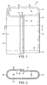
FIG. 1 illustrates a schematic view of an end-seal, shrink bag having a lap seal according to the present invention, in a slightly open position from a lay-flat position. -
FIG. 2 illustrates a transverse cross-sectional view of the bag illustrated inFIG. 1 , taken through section 2-2 ofFIG. 1 . -
FIG. 3 illustrates a schematic view of an end-seal, shrink bag having a fin seal according to the present invention, in a slightly open position from a lay-flat position. -
FIG. 4 illustrates a transverse cross-sectional view of the bag illustrated inFIG. 3 , taken through section 4-4 ofFIG. 3 . -
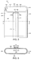
FIG. 5 illustrates a schematic view of an end-seal, shrink bag having a butt-seal according to the present invention, in a slightly open position from a lay-flat position. -
FIG. 6 illustrates a transverse cross-sectional view of the bag illustrated inFIG. 5 , taken through section 6-6 ofFIG. 5 . -
FIG. 7 illustrates a preferred three-layer film structure for forming bags according to the present invention. -
FIG. 8 is a schematic representation of a preferred method of manufacturing films for use with the present invention. -
FIG. 9 illustrates a preferred seven-layer film structure for forming bags according to the present invention. -
FIG. 10 illustrates a schematic view of a film suitable for making a peelable sealed heat shrink bag according to the present invention. -
FIG. 11 illustrates a schematic view of a preferred embodiment of a heat-shrinkable bag according to the present invention, in a substantially lay-flat position. -
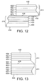
FIG. 12 illustrates a fragmentary cross-sectional view taken along lines A-A ofFIG. 11 depicting an enlarged, not to scale, lap seal area of a preferred film for use in fabricating the bag illustrated inFIGS. 11 ,13 and14 . -
FIG. 13 illustrates a fragmentary cross-sectional view taken along lines B-B ofFIG. 11 depicting an enlarged, not to scale, end seal area of a preferred film. -
FIG. 14 illustrates schematic view of another preferred embodiment of a heat-shrinkable bag according to the present invention having a pull flap. -
FIG. 15 illustrates a transverse cross-sectional view of the bag illustrated inFIG. 14 , taken through section C-C ofFIG. 14 . -
FIG. 16 illustrates a cross-sectional view taken along lines D-D ofFIG. 15 , depicting an end seal. -
FIG. 17 illustrates yet another bag according to the present invention having a fin seal backseam. -
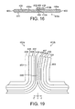
FIG. 18 illustrates a cross-sectional view of the bag illustrated inFIG. 17 , taken through section E-E. -
FIG. 19 illustrates an enlarged fragmentary cross-sectional view of the seal portion of FIG. - 18 detailing a preferred film structure.
-
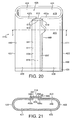
FIG. 20 illustrates another bag embodiment according to the present invention having a butt-seal backseam. -
FIG. 21 illustrates a cross-sectional view of the bag illustrated inFIG. 20 , taken through section F-F. -
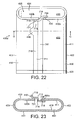
FIG. 22 illustrates another bag according to the present invention having a peel strip. -
FIG. 23 illustrates a cross-sectional view of the bag illustrated inFIG. 22 , taken along section G-G. -
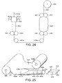
FIG. 24 is a schematic illustration of a preferred method of manufacturing films for use with the present invention. -
FIG. 25 is a schematic illustration of a preferred method of manufacturing bags according to the present invention. - A preferred embodiment of the heat-shrinkable packaging receptacle of the present invention is shown in
FIGS. 1 and 2 generally asbag 10. Thebag 10 is formed from a sheet of heart-shrinkable film 11 having afirst edge 12, asecond edge 14, atop surface 13 and abottom surface 15. Thebag 10 includes afirst seal 16 bonding the first andsecond edges tube member 18 is formed, shown inFIGS. 1 and 2 in a partially lay-flat orientation, having afirst bag wall 20, asecond bag wall 22, afirst bag edge 24, asecond bag edge 26, anopening 28 and abag end 30. In other words, the first andsecond edges top surface 13 of thefirst edge 12 andbottom surface 15 of thesecond edge 14 such that thetop surface 13 of thefirst edge 12 is sealed in face-to-face contact with thebottom surface 15 of the second edge. Thebag 10 includes asecond seal 32 provided through the first andsecond bag walls bag 10 from thefirst bag edge 24 to thesecond bag edge 26, thereby closing thebag end 30 and defining aproduct receiving chamber 34. - Although the
first seal 16 is illustrated as being positioned between the first and second tube edges 24 and 26 and running parallel thereto, one skilled in the art will appreciate in view of the present disclosure that the position of thefirst seal 16, when thebag 10 is in a lay-flat orientation, may be any desired position fromfirst edge 24 tosecond edge 26 of either first orsecond bag walls second seal 32 is illustrated as being straight and extending perpendicular to thefirst seal 16; however, the skilled artisan will appreciate that thesecond seal 32 may take any shape, so long as thesecond seal 32 operates to close thebag end 30 and thereby define aproduct receiving chamber 34. For example, common seal configurations include straight, or linear, seals which usually extend perpendicular to the tube edges 24 and 26 (the tube edges 24 and 26 generally extend parallel to each other), and also include nonlinear or curved edges, e.g., such as those described inU.S. Patent No. 5,149,943 , which patent is hereby incorporated by reference in its entirety. Both linear and nonlinear seals may be made by any suitable sealing method known, including hot bar and impulse sealing. - A second embodiment of the heat-shrinkable packaging receptacle of the present invention is illustrated in
FIGS. 3 and 4 generally asbag 110. Thebag 110 is formed from a sheet of heat-shrinkable film 111 having afirst edge 112, asecond edge 114, atop surface 113 and abottom surface 115. Thebag 110 includes afirst seal 116 bonding the first andsecond edges tube member 118. To form thefirst seal 116, the first andsecond edges bottom surface 115 of both the first andsecond edges tube member 118 is shown inFIGS. 3 and 4 in a partially lay-flat orientation, defining afirst bag wall 120, asecond bag wall 122, afirst bag edge 124, asecond bag edge 126, anopening 128 and abag end 130. Thebag 110 includes asecond seal 132 provided through the first andsecond bag walls bag 110 from thefirst bag edge 124 to thesecond bag edge 126, thereby closing thebag end 130 and defining aproduct receiving chamber 134. - Again, although the
first seal 116 has been illustrated as being positioned between the first and second tube edges 124 and 126, one skilled in the art will appreciate in view of the present disclosure that the location of thefirst seal 116, when thebag 110 is in a lay-flat orientation, may be any desired position fromfirst edge 124 tosecond edge 126 of either first orsecond tube walls second edges first seal 116 forms afin 117 that extends outwardly from thetube member 118, thefirst seal 116 is preferably positioned at a point between the first and second tube edges 124 and 126 at or near the middle of a bag wall. In this manner, thefin 117 may be folded over flat against the respective bag wall from which it extends and thesecond seal 132 and final closing seal (not shown) will operate to maintain thefin 117 in such a folded position. This advantageously eliminates an unwanted, unaesthetic fin seal at the side edge of a packaged product. Similar tosecond seal 32, thesecond seal 132 is illustrated as being straight and extending perpendicular to thefirst seal 116. The skilled artisan will appreciate that thesecond seal 132 may take any shape, such as a curved shape, so long as thesecond seal 132 operates to close thebag end 130 and thereby define aproduct receiving chamber 134, as described with respect to thesecond seal 32. - Another embodiment of the present invention is illustrated in
FIGS. 5 and 6 generally asbag 210.Bag 210 is formed from a sheet of heat-shrinkable film 210 having afirst edge 212, asecond edges 214, aninner surface 213 and anouter surface 215. Thebag 210 includes afirst seal 216 comprising a butt-seal, that bonds the first andsecond edges second edges first seal 216 preferably includes a butt-seal tape 217, one side of which is sealed to theouter surface 215 of thefirst edge 212 byseal 216a, while an opposing side of thetape 217 is sealed to the outer surface of the second edge byseal 216b,seals second edges first seal 216 defines atube member 218, shown inFIGS 5 and 6 in a partially lay-flat orientation, having afirst bag wall 220, asecond bag wall 222, afirst bag edge 224, asecond bag edge 226, anopening 228 and abag end 230. Thebag 210 includes a second seal 232 provided through the first andsecond bag walls bag 210 from thefirst bag edge 224 to thesecond bag edge 226, thereby closing thebag end 230 and defining aproduct receiving chamber 234. - The film used to fabricate the bags of the present invention may be multilayer or monolayer flexible, heat-shrinkable film manufactured by any known process. For example, in commercial poultry packaging operations, monolayer films made from polyethylene and/or ethylene-vinyl acetate copolymers, and multilayer films containing polyethylene and/or ethylene-vinyl acetate copolymers are used extensively. Likewise, in the packaging of fresh red meat and processed meat products, multilayer heat-shrinkable films containing polyethylene and/or ethylene-vinyl acetate copolymers in one or more layers of the films are commonly employed. Preferred films may also provide a beneficial combination of one or more or all of the below noted properties including high puncture resistance (e.g. as measured by the ram and/or hot water puncture tests), high shrinkage values, low haze, high gloss, and high seal strengths. The film and/or bags may also include an indicia, such as they may be printed. For example, bags according to the invention may preferably include an indicia indicating that the bag includes a bone-containing product. It may be desirable for applications wherein the film is printed to corona treat the film surface to improve ink adhesion. Since corona treated surfaces do not normally heat seal as well as untreated surfaces, it may be desirable to corona treat only those portions that will not form part of a heat seal or to limit the treated area of the film to minimize adverse interaction with later sealed areas. For example, a center portion of the film may be corona treated, while those portions along each of the machine direction edges of the film are not. In this manner, those portions along each machine direction edge, that are sealed together to form the
first seals - Preferably, the film may have an unrestrained shrinkage of at least 20% in at least one direction and more preferably 35% or more in one or both the machine and transverse directions. Free shrink is measured by cutting a square piece of film measuring 10 cm in each of the machine and transverse directions. The film is immersed in water at 90 °C for five seconds. After removal from the water the piece is measured and the difference from the original dimension is multiplied by ten to obtain the percentage of shrink.
- Although the films used in the bag according to the present invention can be monolayer or multilayer films, the bags are preferably formed of a multilayer film having 2 or more layers; more preferably 3 to 9 layers; and still more preferably 3 to 5 to 7 layers. Since the inventive bags are primarily intended to hold food products after evacuation and sealing, it is preferred to use a thermoplastic film which includes an oxygen and/or moisture barrier layer. The terms "barrier" or "barrier layer" as used herein means a layer of a multilayer film which acts as a physical barrier to moisture or oxygen molecules. Advantageous for packaging of oxygen sensitive materials such as fresh red meat, a barrier layer material in conjunction with the other film layers will provide an oxygen gas transmission rate(O2GTR) of less than 70 (preferably 45 or less, more preferably 15 or less ) cc per square meter in 24 hours at one atmosphere at a temperature of 73°F (23°C) and 0% relative humidity.
- The
bags - The type of
first seal First seal 16, or lap seal, requires that thetop surface 13 andbottom surface 15 be capable of forming a suitable heat seal therebetween. If afirst seal 116, or fin seal, is to be formed, only thebottom surface 115 need be capable of forming a suitable heat seal, since the interfacial bond will be formed between the same surface or layer. If afirst seal 216, or butt-seal, is formed, then both the top surface and bottom surfaces must be capable of forming a suitable heat seal. Likewise, the butt-seal tape 217, must also be capable of forming a suitable heat seal with the top surface or a suitable adhesive must be employed to adhere thetape 217 to thetop surface 13 orbottom surface 15, depending on whether thetape 217 is place on the inside or outside of thebag 110. - A preferred multilayer barrier film structure for use with the present invention is shown in
FIG. 7 generally as 40. When anoxygen barrier layer 42 is needed, it is usually provided as a separate layer of a multilayer film, most commonly as a core layer sandwiched between an innerheat sealing layer 44 and anouter layer 46, though additional layers may also be included, such as tie or adhesive layers as well as layers to add or modify various properties of the desired film, e.g., heat sealability, toughness, abrasion resistance, tear-resistance, heat shrinkability, delamination resistance, stiffness, moisture resistance, optical properties, printability, etc. Oxygen barrier materials which may be included in the films utilized for the inventive bags include ethylene vinyl alcohol copolymers (EVOH), polyacrylonitriles, polyamides and vinylidene chloride copolymers (PVDC). Preferred oxygen barrier polymers for use with the present invention are vinylidene chloride copolymers or vinylidene chloride with various comonomers such as vinyl chloride (VC-VDC copolymer) or methyl acrylate (MA-VDC copolymer), as well as EVOH. A specifically preferred barrier layer comprises about 85% vinylidene chloride-methyl acrylate comonomer and about 15% vinylidene chloride-vinyl chloride comonomer, as for example described inSchuetz et al. U.S. Pat. No. 4,798,751 . Suitable and preferred EVOH copolymers are described inU.S. Patent No. 5,759,648 . The teachings of both the '751 and '648 patents are hereby incorporated by reference in their entireties. - The inner
heat sealing layer 44 is generally provided on a side of thebarrier layer 42 that becomes theinner surface 38, orbottom surfaces Figs. 1-6 , of thebags barrier layer 42 and the innerheat sealing layer 44 as previously noted. Substantially linear copolymers of ethylene and at least one alpha-olefin as well as copolymers of ethylene and vinyl esters or alkyl acrylates, such as vinyl acetate, may be usefully employed in one or more layers of the film, and may comprise monolayer and multilayer thermoplastic films. Preferably, the inner heat sealing layer comprises a blend of at least one ethylene-α-olefin copolymer (EAO), with ethylene vinyl acetate (EAO:EVA blend). Suitable α-olefins include C3 to C10 alpha-olefins such as propene, butene-1, pentene-1, hexene-1, methylpentene-1, octene-1, decene-1 and combinations thereof. The heat seal layer is optionally the thickest layer of a multilayer film and may significantly contribute to the puncture resistance of the film. Another desirable characteristic affected by this layer is the heat seal temperature range. It is preferred that the temperature range for heat sealing the film be as broad as possible. This allows greater variation in the operation of the heat sealing equipment relative to a film having a very narrow range. For example, it is desirable for a suitable film to heat seal over a broad temperature range providing a heat sealing window of 80°F or higher. - The
outer layer 46 is provided on the side of the barrier layer opposite theheat sealing layer 44 and acts as theouter surface 39. In the instance when a lap seal, such as thefirst seal 32 ofbag 10 is incorporated into a bag structure, theouter layer 46 must be heat seal compatible with the inner heat sealing layer. Other polymer layers may optionally be provided between the barrier layer and the outer layer as previously discussed. The outer layer may comprise an ethylene-α-olefin copolymer (EAO), ethylene vinyl acetate copolymer (EVA) or blends thereof. EAOs are copolymers predominately comprising ethylene polymeric units copolymerized with less than 50 % by weight of one or more suitable α-olefins which include C3 to C10 alpha-olefins such as propene, butene-1, pentene-1, hexene-1, methylpentene-1, octene-1, decene-1. Preferred alpha-olefins are hexene-1 and octene-1. Recent developments for improving properties of a heat-shrinkable film includeU.S. Pat. No. 5,403,668 , incorporated herein, which discloses a multilayer heat-shrinkable oxygen barrier film wherein the film outer layer is a four component blend of VLDPE, LLDPE, EVA and plastomer. LLDPE, or linear low density polyethylene, is a class of ethylene-alpha olefin copolymers having a density greater than 0.915 g/cm3. VLDPE, also called ultra low density polyethylene (ULDPE), is a class of ethylene-alpha olefin copolymers having a density less than 0.915 g/cm3 and many commercial VLDPE resins are available having densities from 0.900 up to 0.915 g/cm3. Plastomers are generally EAOs having densities below 0.900 g/cm3.U.S. Pat. No. 5,397,640 discloses a multilayer oxygen barrier film wherein at least one outer film layer is a three component blend of VLDPE, EVA and a plastomer. Alternatively, the outer layer may be formed of other thermoplastic materials as for example polyamide, styrenic copolymers, e.g., styrenebutadiene copolymer, polypropylene, ethylene-propylene copolymer, ionomer, or an alpha olefin polymer and in particular a member of the polyethylene family such as linear low density polyethylene (LLDPE), very low density polyethylene (VLDPE and ULDPE), high density polyethylene (HDPE), low density polyethylene (LDPE), an ethylene vinyl ester copolymer or an ethylene alkyl acrylate copolymer or various blends of two or more of these materials. - In general, the monolayer or multilayer films used in the heat-shrinkable bags of the present invention can have any thickness desired, so long as the films have sufficient thickness and composition to provide the desired properties for the particular packaging operation in which the film is used, e.g., puncture-resistance, modulus, seal strength, barrier, optics, etc. For efficiency and conservation of materials, it is desirable to provide the necessary puncture-resistance and other properties using the minimum film thicknesses. Preferably, the film has a total thickness from about 1.25 to about 8.0 mils; more preferably from about 1.75 to about 3.0 mils.
- Suitable films for use with the present invention are disclosed in
U.S. Patent No. 5,928,740 , incorporated herein by reference thereto in its entirety. The '740 patent discloses a heat sealing layer comprising a blend of a first polymer of ethylene and at least one α-olefin having a polymer melting point between 55 to 75 °C.; a second polymer of ethylene and at least one α-olefin having a polymer melting point between 85 to 110 °C and a third thermoplastic polymer having a melting point between 115 to 130 °C which is preferably selected from the group of ethylene homopolymers such as HDPE and LDPE, and ethylene copolymers with at least one α-olefin; and optionally and preferably a fourth polymer such as a copolymer of ethylene with an alkyl acrylate or vinyl ester having a melting point between 80 to 105 °C, preferably 90 to 100 °C. The '740 patent also discloses a preferred biaxially oriented, heat-shrinkable three-layer barrier film embodiment for use with the present invention. The three-layer barrier film embodiment comprises an inner heat sealing layer as described above in conjunction with a barrier layer preferably comprising a polyvinylidene chloride (PVDC) or vinylidene chloride methylacrylate copolymer (VDC-MA or MA-saran) or EVOH layer and an outer layer formed of at least 50 wt. %, and preferably at least 70%, of a copolymer of ethylene with at least one alpha-olefin or at least one vinyl ester or blends thereof. Also, preferred EVAs will have between about 3% and about 18% vinyl acetate content. - Preferred films for use with the present invention are disclosed in
U.S. Patent Application Ser. No. 09/401,692 filed September 22, 1999 - Additional preferred films for use with the present invention are disclosed in
U.S. Patent Application Ser. No. 09/611,192 filed July 6, 2000 M w/M n of from 1.5 to 3.5; 0 to 90 weight percent of (iii) a copolymer of ethylene and at least one C4 to C8 α-olefin, having a melting point of from 100 to 125°C; and 0 to 90 weight percent of (iv) a copolymer of propylene and at least one monomer selected from the group of ethylene and butene-1, where the copolymer (iv) has a melting point of from 105 to 145°C; 0 to 90 weight percent of (v) a copolymer of ethylene and at least one monomer selected from the group of hexene-1, octene-1 and decene-1, where the copolymer (v) has a melting point of from 125 to 135°C; and polymers (ii), (iii), (iv), and (v) have a combined weight percentage of at least 80 weight percent based upon the total weight of polymers (i), (ii), (iii), (iv), and (v); and wherein the film has a total energy absorption of at least 1.2 Joule. Optionally, the same blend may be used as an inner heat sealing layer for a bag film. - Further preferred films for use with the present invention are described in
U.S. Pat. No. 5,302,402 to Dudenhoeffer et al .,U.S. Pat. No. 6,171,627, Lustig et al. U.S. Pat. No. 4,863,769 , andU.S. Pat. No. 6,015,235 to Kraimer et al. , all of which are incorporated herein in their entireties. - In a preferred embodiment of the present invention, the heat-shrinkable bag is formed of a three-layer film. The three-layer film is preferably a biaxially oriented film including a barrier layer disposed between an inner heat sealing layer and an outer layer, as shown in
FIG. 5 . The inner heat sealing layer comprises a blend of about 37% of an ethylene-vinyl acetate (EVA) copolymer such as ESCORENE™ LD 701.ID available from Exxon Chemical Co., Houston, Texas, USA; about 24% VLDPE resin such as SCLAIR™ 10B available from Nova Chemicals, Ltd., Calgary, Alberta, Canada (0.77 dg/min Melt Index and 0.911 g/cm3 density); about 33% of a plastomer, such as EXACT™ 4053 available from Exxon Chemical Co., Houston, Texas, USA; about 4% slip/processing aid, such as Spartech A27023 (slip/processing aid in a VLDPE carrier resin); and about 2% of a processing stabilizer such as Spartech A32434 (available from Spartech Polycom of Washington, Pennsylvania, U.S.A.). The barrier layer comprises a blend of about 15% vinylidene chloride-vinyl chloride and about 85% vinylidene chloride-methacrylate, such as further described inU.S. Patent No. 4,798,751 . The outer layer comprises a blend of about 40% of an ethylene-vinyl acetate (EVA) copolymer such as ESCORENE™ LD 701.ID; about 33% of a plastomer, such as EXACT™ 4053; about 25% of a VLDPE resin, such as SCLAIR™ 10B; and about 2% of a processing aid/slip concentrate in a VLDPE carrier, such as Ampacet 501236, available from Ampacet Corporation, Tarrytown, New York, USA. The inner layer, barrier layer and outer layer represent about 57.7%, 17.7% and 25.1% respectively based on the total thickness of the three-layer film. - In another preferred embodiment of the present invention, the heat-shrinkable bag is formed of another three-layer biaxially oriented shrink film including a barrier layer disposed between an inner heat sealing layer and an outer layer, as shown in
FIG. 5 . The barrier layer preferably comprises a blend of about 15% vinylidene chloride-vinyl chloride and about 85% vinylidene chloride-methacrylate such as further described inU.S. Patent No. 4,798,751 . The barrier layer preferably comprises approximately 16.5% of the three-layer film's thickness. The inner heat sealing layer preferably comprises about 57.1% of the film's thickness and comprises a blend of about 35.1 wt. % of an ethylene-hexene-1 copolymer such as EXACT™ 9519 ( 0.895 g/cm3 and 2.2 dg/min Melt Index available from Exxon Chemical Co., Houston, Texas, USA); about 36.5% of an ethylene-octene-1 copolymer such as ATTANE™ XU 61509.32 (a C2C8 (<10 wt. % C8) VLDPE having a density of about 0.912 g/cm3 and 0.5 dg/min Melt Index available from Dow Chemical Co., Midland, Michigan, USA); about 26.5% of an ethylene-vinyl acetate (EVA) copolymer such as ESCORENE™ LD 701.ID (an ethylene-vinyl acetate copolymer available from Exxon Chemical Co., Houston, Texas, USA and reportedly having a density of 0.93 g/cm3, a vinyl acetate content of 10.5 wt. %, a melt index of about 0.19 dg/min., and a melting point of about 97 °C); about 3% of a slip/processing aid such as Spartech A50050 (1.9% oleamide slip and an fluoroelastomer in a VLDPE carrier resin); and about 2% of a processing stabilizer such as Spartech A32434 (10% DHT4A in VLDPE carrier resin available from Spartech Polycom of Washington, Pennsylvania, U.S.A.). The outer layer preferably comprises about 26.4% of the film thickness and comprises about 35 wt. % of an ethylene-hexene-1 copolymer such as EXACT™ 9519; about 35 % of a ethylene-octene-1 copolymer such as ATTANE™ XU 61509.32; about 27% of a EVA copolymer such as ESCORENE™ LD 701.ID; and about 3% of a slip/processing aid such as Spartech A50050 (available from Spartech Polycom of Washington, Pennsylvania, U.S.A.). - In another preferred embodiment, the film of the bag comprises a biaxially oriented three-layer heat-shrinkable film having an inner heat sealing layer made of a blend of about 17 wt. % ethylene-octene-1 copolymer such as ATTANE™ XU 61509.32; about 18 wt. % EVA such ESCORENE™ LD 701.ID; 5 8% of an ethylene-hexene-1 copolymer such as EXACT™ 9110 (0.898 g/cm3 density, 0.8 dg/min Melt Index and 89 °C melting point); about 2% of a processing stabilizer such as Spartech A32434; and about 5% of a slip/processing aid such as Spartech A50050. The outer layer is about 19 wt. % ethylene octene-1 copolymer such as ATTANE™ XU 61509.32; 18% EVA (ESCORENE™ LD 701.ID); 60% of an ethylene-hexene-1 copolymer such as EXACT™ 9110; and 3% processing aid such as A50056. The barrier layer is 85% vinylidene chloride-methyl acrylate and about 15% vinylidene chloride-vinyl chloride. Preferably, the inner layer:barrier layer:outer layer thickness ratio is about 62:9:29.
- A preferred seven-layer film for use in fabricating bags according to the present invention is illustrated in
FIG. 9 generally asfilm 60. Thefilm 60 includes a first or innerheat sealing layer 61 preferably comprising about 10% of the total mass of thefilm 60. The innerheat sealing layer 61 preferably comprises a blend of about 94% EXACT™ 3139 (an ethylene-hexene copolymer having a reported Melt Index of 7.5 g/10 min and a density of 0.900 g/cm3); about 4% Spartech A27023; and about 2% Spartech A32434. Asecond layer 62, adjacent thefirst layer 61 preferably comprises about 42.2% of the total mass of the film and comprises a blend of about 37% ESCORENE™ LD 701.ID; about 33% EXACT 4053; about 24% SCLAIR™ 10B; about 4% Spartech A27023; and about 2% Spartech A32434. Thefilm 60 further includes first and second tie layers 63 and 65, each of which individually preferably comprise about 5% of the total mass of thefilm 60 and further comprise about 100% of VORIDIAN™ SP1330, an ethylene-methyl acrylate copolymer available form Voridian, a division of Eastman Chemical Company, Kingsport, Tennessee, USA. Thefilm 60 includes abarrier layer 64 between the first and second tie layers 63. Thebarrier layer 64 preferably comprises about 17.7% of the total mass of the film and comprises a blend of about 85% vinylidene chloride-methyl acrylate and about 15% vinylidene chloride-vinyl chloride. Th film includes athird layer 66 that preferably comprises about 15.1% of the total mass of thefilm 60. Thethird layer 66 comprises a blend of about 40% ESCORENE™ 701.ID; about 33% EXACT™ 4053; about 25% SCLAIR™ 10B; and about 2% Spartech A27339. Thefilm 60 includes a fourth layer orouter layer 67 that preferably comprises about 5% of the total mass offilm 60 and comprises a blend of about 98% EXACT™ 3139 and about 2% Spartech A27339. The total thickness of thefilm 60 is preferably about 2 mils or greater. - Advantageously, it may be desirable to utilize high Melt Flow Index polymers in sealant layer(s) of the film to aid in transversely sealing across the lap, butt or fin seals. High Melt Flow polymers, having a Melt Flow Index greater than about 5 dg/min. The higher Melt Flow Index polymers fill gaps, such as
gaps 9a (FIG. 2 ), 9b (FIG. 4 ) and 9c (FIG. 6 ) that may form due to the dimensional difference encountered when thesecond seals first seals outer layers film 60 to replace the lower Melt Index ethylene-hexene copolymer. - The films selected to fabricate the inventive receptacles are preferably biaxially oriented by the well-known trapped bubble or double bubble technique as for example described in Pahlke
U.S. Pat. No. 3,456,044 . In this technique an extruded primary tube leaving the tubular extrusion die is cooled, collapsed and then preferably oriented by reheating and reinflating to form a secondary bubble. The film is preferably biaxially oriented wherein transverse (TD) orientation is accomplished by inflation to radially expand the heated film. Machine direction (MD) orientation is preferably accomplished with the use of nip rolls rotating at different speeds to pull or draw the film tube in the machine direction. - The stretch ratio in the biaxial orientation to form the bag material is preferably sufficient to provide a film with total thickness of between about 1.5 and 3.5 mils. The MD stretch ratio is typically 3:1-5:1 and the TD stretch ratio is also typically 3:1-5:1.
- Referring now to
FIG. 8 , a double bubble or trapped bubble process is shown. The polymer blends making up the several layers are coextruded by conveyingseparate melt streams die 330. These polymer melts are joined together and coextruded fromannular die 330 as a relatively thick walledmultilayered tube 332. The thick walledprimary tube 332 leaving the extrusion die is cooled and collapsed by niprollers 331 and the collapsedprimary tube 332 is conveyed bytransport rollers tube 332 is then reheated to below the melting point of the layers being oriented and inflated with a trapped fluid, preferably gas, most preferably air, to form asecondary bubble 334 and cooled. Thesecondary bubble 334 is formed by a fluid trapped between a first pair of niprollers 336 at one end of the bubble and a second pair of niprollers 337 at the opposing end of the bubble. The inflation which radially expands the film provides transverse direction (TD) orientation. Orientation in the machine direction (MD) is accomplished by adjusting the relative speed and/or size of niprollers 336 and niprollers 337 to stretch (draw) the film in the machine direction.Rollers 337 also collapse the bubble forming an orientedfilm 338 in a lay-flat condition which may be wound on areel 339 or slit for further processing close up. - The biaxial orientation preferably is sufficient to provide a multilayer film with a total thickness of from about 1.25 to about 8.0 mils, preferably 1.5 to 4 mils or more, preferably between 1.75 and 3.0 mils (44 to 76 µ), and more preferably about 2.5 mils.
- A preferred film and process for making film suitable for use in fabricating bags according to the present invention is described in each of
U.S. Patent Applications No. 09/401,692 filed September 22, 1999 09/431,931 filed November 1, 1999 09/611,192 filed July 6, 2000 - For a monolayer film, the process is similar but utilizes a single extruder (or multiple extruders running the same polymeric formulation) to produce a primary tube, and biaxial orientation is sufficient to provide a monolayer film preferably having a total thickness of between 2 to 6 mil or higher, and more typically from about 3.5 to 4.5 mils and is generally in the same draw ratio range as previously discussed, namely about 3:1 to 5:1 for both the MD and TD.
- Although not essential, it is preferred to irradiate the film to broaden the heat sealing range and/or enhance the toughness properties of the inner and outer layers by irradiation induced cross-linking and/or scission. This is preferably accomplished by irradiation with an electron beam at a dosage level of at least 2 megarads (MR) and preferably in the range of 3-5 MR, although higher dosages may be utilized, such as for thicker films. Irradiation may be provided on the primary tube or after biaxial orientation. The latter, called post-irradiation, is preferred and described in
Lustig et al. U.S. Patent No. 4,737,391 , which is hereby incorporated by reference. - After orientation, the
tubular film 338 is collapsed, slit open longitudinally, laid flat and wound on areel 339 for use as rollstock. One skilled in the art will appreciate that the above method may be used to form the film, films may be made by conventional single bubble, blown film processes, and oriented or nonoriented sheets may be made by slot cast sheet extrusion processes with or without tentering to provide orientation. One skilled in the art will further appreciate that the flatwidth of the collapsed tube will determine the width of the sheet film that results therefrom. Thus, the primary tube dimensions and subsequent processing may be selected to provide a maximum flatwidth and film thickness for the desired application, thereby advantageously maximizing the production capacity of the film making equipment. - Advantageously, a bag maker may produce bags of various lengths and widths from rolls of film rollstock by adjusting the width of the sheet (by slitting or cutting rollstock to a desired width) and the distances between the transverse end seal and bag mouth for a particular bag or series of bags. This advantageously avoids the costly need to produce specific widths of seamless tubes which are currently widely used by meat packers. Also the present invention permits cost savings and manufacturing efficiencies by permitting creation of numerous widths and lengths of bag from standard rollstock, which was produced utilizing substantially 100% of the film producing equipment's capacity. This reduces the need to carry larger inventories of a vast array of seamless tube rollstock having different widths. The bag maker may simply slit film rollstock to a desired width and form a continuous tube member by longitudinally sealing opposing side edges as described for
bags bags - Preferably, bag making is a continuous process, wherein the film is directed to a bag making assembly (not shown) where individual end-seal bags are made. As previously stated, the rollstock may be slit to a desired width with the unused portion re-wound for later use. Bags are produced by continuously bringing the opposing side edges of the film together and forming a heat seal, such as a lap seal or fin seal to form a continuous tube member, then making lateral, or transverse, heat seals across the tube member width at spaced intervals to weld the first and second bag walls of the tube member together. The tube member is severed preferably at the same time or during the same step that it is transversely heat sealed to form a bag as shown in
Figure 1 ,3 or5 . Typically as the transverse seal is made for one bag a transverse cut forming the mouth of the adjacent bag is being made. This process forms a so called "end-seal" bag which, when it is laid flat, has a bottom edge formed by the transverse heat seal, an open mouth formed by the severed edge and two side edges formed by the fold produced when the tube member is laid flat. The transverse heat seal should extend across the entire tube member to ensure a hermetic closure. Each bag being formed from a length of the tube member will necessarily be formed by at least two, usually parallel, spaced apart, transverse cuts which cause a segment of the tube member to be made and one transverse seal, usually adjacent one of these cuts, will define a bag bottom which is located opposing the bag opening, which is formed by the distal cut. In typical production the member tube is transversely sealed and an adjacent transverse cut made as part of the same step and the seal and this proximate cut form a sealed end for one bag while the same cut also forms the mouth opening for the adjacent bag, and for that adjacent bag may be referred to as the distal cut. The spacing between the lateral seal and the point of severance, which may vary, will determine the length of the bags formed. The length of the bags can easily be varied by changing the distance between cuts. The width of the bags can also be easily varied by changing the width of the film by slitting the standard rollstock. In another embodiment of the invention, cuts and seals may be made alternately and apart from each other to form dual attached bags in saddle bag fashion. - The present invention advantageously provides for producing a heat-shrinkable bag wherein the bag manufacturer may produce multiple bag sizes (different lengths and widths) from a single film stock size, which advantageously maximizes film production efficiency by eliminating the need to manufacture different widths of seamless tubes. In other words, the present invention allows the bag manufacturer to produce one standard width of sheet film stock, such as 86, 94, 98, 104, 112, 126, 162 inch or greater, depending on the capacity of the film producing equipment. This standard sheet film stock may then be slit to a desired width, formed into a bag as described herein, and the remaining portion of the sheet film stock rewound for later use on another job. Prior art bags require the manufacturer thereof to produce different seamless tube sizes for each size of bag produced, thereby reducing production efficiency.
- Unless otherwise noted, the following physical properties are used to describe the invention, films and seals. These properties are measured by either the test procedures described below or tests similar to the following methods.
Average Gauge: ASTM D-2103
Tensile Strength: ASTM D-882, method A
1% Secant Modulus: ASTM D-882, method A
Oxygen Gas Transmission Rate (O2GTR): ASTM D-3985-81
Percent Elongation at Break: ASTM D-882, method A
Molecular Weight Distribution: Gel permeation chromatography
Gloss: ASTM D-2457, 45° Angle
Haze: ASTM D-1003-52
Melt Index: ASTM D-1238, Condition E (190°C) (except for propene-based (>50% C3 content) polymers tested at Condition L(230°C.))
Melting Point: ASTM D-3418, peak m.p. determined by DSC with a 10°C/min. heating rate.
Vicat Softening Point (Vsp): ASTM D-1525-82
Seal Strength: ASTM F88-94 - All ASTM test methods noted herein are incorporated by reference into this disclosure.
- Shrinkage Values: Shrinkage values are obtained by measuring unrestrained shrink of a 10 cm. square sample immersed in water at 90°C (or the indicated temperature if different) for ten seconds. Four test specimens are cut from a given sample of the film to be tested. Specimens are cut into squares of 10 cm length (M.D.) by 10 cm. length (T.D.). Each specimen is completely immersed for 10 seconds in a 90°C (or the indicated temperature if different) water bath. The specimen is then removed from the bath and the distance between the ends of the shrunken specimen is measured for both the M.D. and T.D. directions. The difference in the measured distance for the shrunken specimen and each original 10 cm. side is multiplied by ten to obtain percent shrinkage in each direction. The shrinkage of 4 specimens is averaged and the average M.D. and T.D. shrinkage values reported. The term "heat shrinkable film at 90°C" means a film having an unrestrained shrinkage value of at least 10% in at least one direction.
- Five identical samples of film are cut 1 inch (2.54 cm) wide and a suitable length for the test equipment e.g. about 5 inches (77 cm) long with a 1 inch (2.54 cm) wide seal portion centrally and transversely disposed. Opposing end portions of a film sample are secured in opposing clamps in a universal tensile testing instrument. The film is secured in a taut snug fit between the clamps without stretching prior to beginning the test. The test is conducted at an ambient or room temperature (RT) (about 23 °C) test temperature. The instrument is activated to pull the film via the clamps transverse to the seal at a uniform rate of 12.0 inches (30.48 cm) per minute until failure of the film (breakage of film or seal, or delamination and loss of film integrity). The test temperature noted and lbs. force at break are measured and recorded. The test is repeated for four additional samples and the average grams at break reported.
- The ram puncture test is used to determine the maximum puncture load or force, and the maximum puncture stress of a flexible film when struck by a hemispherically or spherically shaped striker. This test provides a quantitative measure of the puncture resistance of thin plastic films. This test is further described in
U.S. Patent Application No. 09/401,692 . - The following example is given to illustrate the invention and should not be construed as limiting that which is described in the appended claims.
- In the following example, the film composition was produced generally utilizing the apparatus and method described in
U.S. Pat. No. 3,456,044 (Pahlke ) which describes a coextrusion type of double bubble method and in further accordance with the detailed description above. All layers were extruded as a primary tube which was cooled upon exiting the die e.g. by spraying with tap water. This primary tube was then reheated by radiant heaters(although other means known to those skilled in the art, such as conduction or convection heating may be used) with further heating to the draw (orientation) temperature for biaxial orientation accomplished by an air cushion which was itself heated by transverse flow through a heated porous tube concentrically positioned around the moving primary tube. Cooling was accomplished by means of a concentric air ring. Draw point temperature, bubble heating and cooling rates and orientation ratios were generally adjusted to maximize bubble stability and throughput for the desired amount of stretching or orientation. All percentages are by weight unless indicated otherwise. - A puncture-resistant bag according to the present invention, as generally illustrated in
Figs. 1 & 2 , was produced from a film comprising a coextruded three-layer biaxially oriented shrink film having (A) an inner heat sealing layer, (B) a barrier layer and (C) an outer layer. The inner and outer layers being directly attached to opposing sides of the barrier layer. The three layers included the following compositions: - (A) 33 wt. % EXACT™ 4053; 37% ESCORENE™ LD 701.ID; 24% SCLAIR™ 10B; 4% Spartech A27023; and 2% Spartech A32434;
- (B) a blend of about 85% vinylidene chloride-vinyl chloride copolymer and about 15% vinylidene chloride-methacrylate copolymer; and
- (C) 33 wt. % EXACT™ 4053; 25 % SCLAIR™ 10B; 40% ESCORENE™ LD 701.ID; and 2% Ampacet 501236.
- One extruder was used for each layer. Each extruder was connected to an annular coextrusion die from which heat plastified resins were coextruded forming a primary tube. The resin mixture for each layer was fed from a hopper into an attached single screw extruder where the mixture was heat plastified and extruded through a three-layer coextrusion die into the primary tube. The extruder barrel temperature for the barrier layer (B) was between about 250-300°F (121-149°C); for the inner layer (A) and for the outer layer (C) were about 290-330°F(143-165°C). The coextrusion die temperature profile was set from about 320 to 350°F (163 to 177°C). The extruded multilayer primary tube was cooled by spraying with cold tap water 50-68 °F (about 10-20 °C).
- A cooled primary tube of about 4 inches flatwidth was produced passing through a pair of nip rollers. The cooled flattened primary tube was inflated, reheated, biaxially stretched, and cooled again to produce a biaxially stretched and biaxially oriented film which was slit open, laid flat to form a sheet having a width of approximately 16 inches and wound on a reel. The M.D. orientation ratio was about 5:1 and the T.D. orientation ratio was about 4:1 . The draw point or orientation temperature was below the predominant melting point for each layer oriented and above that layer's predominant glass transition point and is believed to be about 68-85 °C. The resultant biaxially oriented film had an average gauge of about 2.5 mil and had an excellent appearance.
- The film was irradiated at a dosage level of about 5.0 MR. As previously noted, although not essential, it is preferred to irradiate the entire film to broaden the heat sealing range and/or enhance the toughness properties of the inner and outer layers by irradiation induced cross-linking and/or scission. Irradiation may be done on the primary tube or after biaxial orientation. The latter, called post-irradiation, is preferred and described in
Lustig et al. U.S. Pat. No. 4,737,391 , which is hereby incorporated by reference. An advantage of post-irradiation is that a relatively thin film is treated instead of the relatively thick primary tube, thereby reducing the power requirement for a given treatment level. - The film was unwound and slit to a width of 13 inches. The film was then fed into the bag making equipment to form a tube member having a continuous longitudinally extending lap seal. Bags according to the
bag 10 depicted inFIG. 1 were formed by sealing laterally across the tube member and simultaneously severing the sealed portion from the continuous tube structure. - Various tests were performed on the film and/or resultant inventive bags. The film thickness was determined to be an average 2.1 mil. The lap seal was tested to have a very strong average seal strength of about 8,000 to 10,000 grams. The bag also had an average M.D. and T.D. heat shrinkability at 90 °C of 48 and 48, respectively. The ram puncture results were likewise impressive. The puncture resistance of the 2.1 mil thick film was measured and had a maximum puncture force of 86 Newtons (N) and a total energy to failure of 0.9 Joules (J). This preferred bag has very good heat shrink percentages which are highly desirable for packaging cuts of fresh red meat and extremely good puncture resistance. Thus, an economical to produce heat shrinkable bag having puncture resistance and strong seals has been made having a unique combination of features and commercial advantages previously unknown.
- Advantageously, the
bags bags first seal first seal 16 or 116). The unused portion slit form the standard roll stock is rewound for use making bags of another dimension(s). In this manner, standard roll stock films can be manufactured more economically because film manufacturing equipment may be run at or near the upper limits of film width production and thereby use nearly all the equipments capacity. Fabricating bags from seamless tubes requires that the film making equipment be run at limited capacities to form the different smaller width tubes. Additionally, the film making equipment requires costly set-up and breakdown between jobs of differing dimensions that add significantly to the cost of manufacturing the seamless tubes. - A preferred embodiment of the heat-shrinkable package of the present invention is made from a
sheet 410 ofheat shrinkable film 411 having afirst side edge 412a and opposing,second side edge 412b connected by athird side edge 412c and afourth side edge 412d. First side edges 412a and second 412b are preferably parallel to each other whenfilm 411 is in a long flat planar state.Third side edge 412c andfourth side 412d are preferably parallel to each other whenfilm 411 is in a lay flat planar state. First andsecond side edges film 411 is in a lay flat planar state.Film 411 has four corners at the intersections of the four sides with first corner 412ac defined by the junction offirst side edge 412a withthird side edge 412c;second corner 412b defined by the junction offirst side edge 412a withthird side edge 412c; second corner 412bc defined by the junction ofsecond side edge 412b withthird side edge 412c; third corner 412ad defined by the junction offirst side edge 412a withfourth side edge 412d; and fourth corner 412bd defined by the junction ofsecond side edge 412b withfourth side edge 412d.Film 411 has atop surface 413a circumscribed by aperimeter 414 formed bysides bottom surface 413b also circumscribed by saidperimeter 414.FIG. 10 Depicts corner 412ad offilm 411 turned upward to reveal saidbottom surface 413b. - Referring now to
FIG. 11 , a preferred embodiment of the present invention is depicted generally as abag 415 made from saidfilm 411 ofFIG. 10 . Thebag 415 is formed by overlapping thefirst side edge 412a with thesecond side edge 412b and sealing preferably by heat to produce a fusionbond lap seal 416 defined by parallel spaced apart dottedlines third side edge 412c andfourth side edge 412d. It should be noted that while saidlap seal 416 is depicted as a continuous elongated rectangle extending fromside 412c toside 412d, the invention further contemplates that the seal shape may vary and could, for example, form a wavy line or zigzag shape or other shapes as desired. Also, the width of the seal may be varied to be thicker or thinner as desired. Also the seal may optionally be made by alternatives or additional means, including, e.g.,by applications of suitable flue or adhesive material known in the art for sealing together films. It is further contemplated that saidlap seal 416, while depicted as acontinuous lap seal 416 suitable for forming a hermetic package, it is also contemplated that for some applications, e.g., for certain industrial or non-perishable items, a noncontinuous seal having, e.g., the appearance of a dotted or dashed line, may be employed. The intermittent seal embodiment permits air to escape enclosure during packaging operations where it is not desired to either apply a vacuum, or seal with a trapped bubble of air or other gas, or remove air by other means. Optionally, the strength of the seal may be varied by one skilled in the art in view of the teachings of the present application by selection of aforesaid parameters such as seal shape, thickness, continuous or intermittent nature, material selection type of and known parameter for varying the strength of different types of seals, e.g., by adjusting dwell time or temperature for producing heat seals. Such variations and adjustments may be made by those skilled in the art without undue experimentation. - Referring again to
FIG. 11 ,lap seal 416 is preferably a heat seal forming a fusion bond betweentop surface 413a andbottom surface 413b offilm 411. The overlapped sealedfilm 411 defines atube member 418 in whichtop surface 413a offilm 411 forms aninner film surface 419 of saidtube member 418. Asecond seal 420 extends laterally across saidtube member 418 adjacent thethird side edge 412c offilm 411 thereby forming aclosed bag end 421. A variety of seals may be used. Preferablysecond seal 420 will be a heat seal which fusion bonds the bag filminner surface 419 to itself. Thesecond seal 420 by closingbag end 421 both forms afirst bag edge 422 and opposingsecond bag edge 423, and the second seal extends across thetube member 418 from thefirst bag edge 422 to thesecond bag edge 423. The second seal may also employ a variety of shapes, thicknesses, structures, etc., as for the previously describedlap seal 416. The lap seal does not need to be centered betweenedges - Opposite the
closed bag end 421 is a bag mount formed by lap sealed film underfourth side edge 412d through which a product (not depicted) may be placed into aproduct receiving chamber 425 defined bytube member 418,closed bag end 421 andbag mouth 424. Thefirst bag edge 422 may extend from a firstbag end corner 426 to a firstbag mouth point 427 and asecond bag edge 423 may extend from a secondbag end corner 428 to a secondbag mouth point 429 such thatbag 415 may be collapsed into a lay flat condition havingfirst bag edge 422 and opposingsecond bag edge 423. In a lay flat condition or a state close to lay flat such as depicted inFIG. 11 ,bag end 421,bag mouth 424 and connectingfirst bag edge 422 andsecond bag edge 423 defines afirst bag wall 430 and connected opposingbag wall 431.Tube member 418 has aninner surface 419 and anouter surface 433. Thefirst bag wall 430 has first bag wallfirst side 430a proximatesecond side edge 412b and extending tosecond bag edge 423. Thefirst bag wall 430 also has an opposing first bag wall seamedside 430b proximatefirst side edge 412a and extending tofirst bag edge 422. - Preferably, the
second seal 420 is provided in a manner such that thefirst seal 416 is positioned within one of the first andsecond bag walls second seal 420 may take any shape, whether straight or curved, so long as thesecond seal 420 operates to close theend 421. At least one of thefirst seal 416 andsecond seal 420 comprises a peelable seal. "Peelable seal" and like terminology is used herein to refer to a seal, and especially heat seals, which are engineered to be readily peelable without uncontrolled or random tearing or rupturing the packaging materials which may result in premature destruction of the package and /or inadvertent contamination or spillage of the contents of the package. An peelable seal is one that can be manually peeled apart to open the package at the seal without resort to a knife or other implement to tear or rupture the package. In the present invention, the peelable seal must have a seal strength sufficient to prevent failure of the seal during the normal heat-shrinking process and further normal handling and transport of the packaged article. The seal strength must also be low enough to permit manual opening of the seal. Preferably seal parameters such as choice of materials and sealing conditions will be used to adjust the seal strength to the desired level for the particular package and application. - Many varieties of peelable seals are known in the art and are suitable for use with the present invention. Peelable seals are generally made from thermoplastic films having a peelable system designed therein. Suitable peelable films and/or peelable systems are disclosed in
U.S. Patent Nos. 4,944,409 (Busche et al. );4,875, 587 (Lulham et al. );3,655,503 (Stanley et al. );4,058,632 (Evans et al. );4,252,846 (Romesberg et al. );4,615,926 (Hsu et al. )4,666,778 (Hwo );4,784,885 (Carespodi );4,882,229 (Hwo );6,476,137 (Longo );5,997,968 (Dries, et al. );4,189,519 (Ticknor );5,547,752 (Yanidis );5,128,414 (Hwo );5,023,121 (Pockat, et al. );4,937,139 (Genske, et al. );4,916,190 (Hwo ); and4,550,141 (Hoh ), the disclosures of which are incorporated herein in their entirety by reference thereto. Preferred films for use in fabricating bags according to the invention may be selected from multilayer, heat-shrinkable films capable of forming a peelable seal. Preferred films may also provide a beneficial combination of one or more or all of the below noted properties including high puncture resistance (e.g., as measured by the ram and/or hot water puncture tests), high shrinkage values, low haze, high gloss, high seal strengths and printability. Since the inventive bags may advantageously be used to hold oxygen or moisture sensitive articles such as food products after evacuation and sealing, it is preferred to use a thermoplastic film which includes an oxygen and/or moisture barrier layer. The terms "barrier" or "barrier layer" as used herein means a layer of a multilayer film which acts as a physical barrier to moisture or oxygen molecules. Advantageous for packaging of oxygen sensitive materials such as fresh red meat, a barrier layer material in conjunction with the other film layers will provide an oxygen gas transmission rate(O2GTR) of less than 70 (preferably 45 or less, more preferably 15 or less ) cc per square meter in 24 hours at one atmosphere at a temperature of 73°F (23°C) and 0% relative humidity. In an alternative embodiment, the gas permeability is controlled to allow the escape of CO2, e.g., for packaging respiring foods such as cheese as described inU.S. Patent No. 6,511,688 . Preferably, the film has an unrestrained shrinkage of at least 20% (preferably at least 35%) at 90°C at least one and preferably both the machine (MD) and transverse (TD) directions. Unrestrained (sometimes referred to as "free") shrink is measured by cutting a square piece of film measuring 10 cm in each of the machine and transverse directions. The film is immersed in water at 90°C for five seconds. After removal from the water the piece is measured and the difference from the original dimensions are each multiplied by ten to obtain the percentage of shrink in each respective direction. - Oxygen barrier materials which may be included in the films utilized for the inventive bags include ethylene vinyl alcohol copolymers (EVOH), polyacrylonitriles, polyamides and vinylidene chloride copolymers (PVDC). For some applications nylon may provide useful oxygen barrier properties especially at low temperatures, e.g., as used with frozen foods. Preferred oxygen barrier polymers for use with the present invention are vinylidene chloride copolymers or vinylidene chloride with various comonomers such as vinyl chloride (VC-VDC copolymer) or methyl acrylate (MA-VDC copolymer), as well as EVOH. A specifically preferred barrier layer comprises about 85% vinylidene chloride-methyl acrylate comonomer and about 15% vinylidene chloride-vinyl chloride comonomer, as for example described in
Schuetz et al. U.S. Pat. No. 4,798,751 . Suitable and preferred EVOH copolymers are described inU.S. Patent No. 5,759,648 . The teachings of both the '751 and '648 patents are hereby incorporated by reference in their entireties. - A variety of peelable films and peelable sealing systems may be employed in the present invention. In a preferred embodiment, a film comprising a coextrusion of at least three layers (referred to as three layer peelable system to distinguish it from systems using one or more contaminated seal layers described below) having an outer layer, an inner heat seal layer and a tie layer disposed between the outer layer and the inner heat seal layer is used. In this preferred three layer system embodiment, the film layers are selected such that peeling occurs by breaking apart the tie layer and/or a bond between the tie layer and at least one of the outer and inner layers. Permanent, peelable, and fracturable bonds may be engineered into the coextrusion process, e.g., by providing two adjacent first and second layers having materials with a greater affinity for each other compared to the second layer and an adjacent third layer where this establishes a relatively permanent bond between the layers, when two materials have a lesser affinity for each other. This three layer structure establishes a relatively permanent bond between the first and second layer which have a greater affinity for one another than the second or third layers which have a lesser affinity where the second layer is common to both the first and third layers as a tie layer or connecting layer. Thus, the lesser affinity between the second and third layers relative to the first and second layers produces a relatively peelable bond between the second and third layers. Selection of the various materials determines the nature of the bond, i.e., whether it is permanent, peelable, fracturable or combinations thereof.
- Suitable polymers for use in the outer, tie and inner heat sealable layers include both poly-type material such as ethylene homopolymers and copolymers as well as ionomer type material. Examples of suitable polymers include: ethylene vinyl acetate copolymer (EVA, ethylene α-olefin copolymers, linear low density polyethylene, low density polyethylene, very low density polyethylene (VLDPE), neutralized ethylene acid copolymer, plastomers, ethylene acrylate copolymer, ethylene methyl acrylate copolymer and zinc or sodium salts of partially or completely neutralized ethylene-methacrylate acid copolymers. The inner heat seal layer beneficially uses heat sealable materials. The tie layer is selected to have a relatively low peel strength when peelably bonded to one of either the outer layer or inner heat seal layer. The tie layer is typically comprised of a blend of about 5-30% polybutylene and another constituent, such as ethylene vinyl acetate copolymer, ethylene copolymers with C4 - C8 alpha olefin, linear low density polyethylene, ionomers, neutralized ethylene acid copolymer or unneutralized ethylene acid copolymer and mixtures thereof. The term "polybutylene" as used herein includes having polymeric units derived from butene -1 as the major (75% polymeric units) components and preferably at least 80% of its polymeric units will be derived from butene -1. A preferred polybutylene is a random copolymer of butene -1 with ethylene having a reported density of 0.908 g/cm3 and a melt index of 1.0 g/10 min. and a melting point of 243°F, which is commercially available from Basell Polyolefins Company, N.V., The Netherlands, under the trade name PB 8640. In this preferred peelable embodiment, the heat seal formed between the inner heat seal layer and another layer to which it is heat sealed, whether part of another film or the same, should be permanent, i.e., should have a seal strength greater than the peelable bond between the tie layer and one of its adjacent layers. The preferred three layer coextruded peeling structure described above contemplates optional additional layers to product a film of 4, 5, 6, 7, 8, 9, 10 or more layers. It is further contemplated that one or more additional layers may be coextruded with the described three layers or separately and that the multilayer film structure may be formed not only by coextrusion, but also by other methods well known in the art such as coating lamination, adhesive lamination or combinations thereof.
- It is also contemplated that such one or more additional layers may be adjacent to or between any of the described three layers. In one embodiment of the invention the heat seal layer may be replaced by a permanent adhesive or glue that may or may not be applied hot or in a melt state, liquid state or otherwise. However, it is preferred to utilize a heat sealable layer.
- It is also contemplated that a peelable seal using one or more so-called "contaminated" surface layers may be utilized where peeling occurs at a
seal layer interface 432 rather than at an interior layer offilm 411. This type of peeling system suffers from disadvantage associate with, e.g., controlling the diverging properties of providing high seal strength with desirable low forms for peelings, as well as problems of sealing under conditions which may adversely affect seal integrity, e.g., where an article being packaged deposits particulates, starch, fat, grease or other components which may lessen seal strength or hamper the ability to provide a seal of desired strength such as a strong hermetic fusion bond, e.g., by heat sealing. Such sealing systems are often referred to as two layer peeling systems, but may include 3, 4, 5, 6, 7, 8, 9, 10 or more layers in the film structure. - Preferred peelable sealing films and peelable seal systems are disclosed in
U.S. Patent No. 4,944,409 entitled "EASY OPEN PACKAGE", the disclosure of which is incorporated herein in its entirety. - A preferred multilayer, barrier film structure for use in fabricating bags according to the present invention is illustrated in
FIG. 12 , which depicts an enlarged, end view of thefirst seal 416 ofFIG. 11 made from the sheet of heat-shrinkable film 411. Layer thicknesses inFIG. 12 and other figures presented herein are not to scale, but are dimensioned for ease of illustration. A preferred easy to peelheat shrinkable film 411 is a five layer coextrusion and includes frominner surface 419 of the tube member 419 (SeeFIG. 11 ) to an opposingouter surface 433. - (a) an inner surface
heat sealing layer 434 preferably comprising a blend of ethylene vinyl acetate (EVA) and polyethylene; - (b) a
barrier layer 435 preferably comprising a vinylidene chloride copolymer (PVDC); - (c) a
core layer 436 preferably comprising a blend of EVA and polyethylene; - (d) a
tie layer 437 preferably comprising a blend of polyethylene and polybutylene; and, - (e) an outer surface
heat sealing layer 438 preferably comprising polyethylene. - The thicknesses of each layer, based on the total thickness of the
film 411, may be typically <50% inner surfaceheat sealing layer 434; <20% barrier layer 435; <28% core layer 436; <15% tie layer 437; and <15% outerheat sealing layer 438. Thefirst seal 416 is made by longitudinally heat sealing theinner film surface 419 offilm 411 to theouter film surface 433 along their respective lengths, such thatinner film surface 419 andouter film surface 433 overlap. In this manner, a fusion bond is made between the inner surfaceheat sealing layer 434 and the outer surfaceheat sealing layer 438. The peelable bond of the system is provided by thetie layer 437 and peeling occurs there, e.g., at the tie layer interface with the outer surfaceheat sealing layer 438, and/or at the tie layer interface withcore layer 436 and/or betweenouter layer 438 andcore layer 436. Thus, referring toFIGS. 11 and12 , the peelable portion of the film is on the outside of thetube member 418, which is preferable. This will insure that thefirst seal 416 is peelable, while thesecond seal 420 and final closing seal (not shown) are strong fusion seals between the inner surfaceheat sealing layer 434 of eachbag wall - Referring to
FIG. 13 , a fragmentary sectional view taken along lines B-B ofFIG. 11 illustrates how a preferred embodiment of the invention works to create strong end seals while permitting the lap seal to function as an easy to open peel seal. InFIG. 13 ,film 411 has anouter surface 433 with consecutive layers therefrom ofouter surface layer 438,tie layer 437,core layer 436,barrier layer 435, and inner surfaceheat sealing layer 434. Referring toFIG. 11 , thesecond seal 420 is provided acrosstube member 418 to collapse itssurface 419 upon itself. Referring again toFIG. 13 , this seal joins inner surfaceheat sealing layer 434 to itself with thepeelable tie layer 437 being positioned distal fromend seal interface 439. This preferred embodiment of the invention depicted inFIGS. 11-13 combines (a) an end seal which mates like materials with strong seal properties to each other keeping distal the easilypeelable tie layer 437 and (b) a lap seal havingpeelable tie layer 437 proximate the outer surfaceheat sealing layer 438 andlap seal interface 432 , thereby providing an easily peelable opening in bags or packages made using the described configuration. - The
film 411 is designed to control the film failure when peeled manually. Due to the composition of thepeelable tie layer 437, its location proximate thelap seal interface 432, and in the case of the preferred three layer peelable system, the thinness and composition of the outer surfaceheat sealing layer 438; as thesecond side edge 412b is manually pulled across, up and away from thelap seal 416, a first rupture or tear will begin. This tear will propagate from the heat seal at theedge 417b oflap seal interface 432 through the outerheat sealing layer 438 thereof. If the peelable bond is designed to occur at thetie layer 437, the continued application of opening force causes: a delamination or breaking of the adhesive bond, along thetie layer 437/outerheat sealing layer 438 interface or along thetie layer 437/core layer 436 interface and/or causes fracture of thetie layer 437, or a combination thereof until the tear reaches theopposite side edge 417a of theheat seal 416, where the tear either propagates to edge 412a or back across theouter layer 438 and the bag is thereby opened. - In general, the films used in the heat-shrinkable bags of the present invention can have any thickness desired, so long as the films have sufficient thickness and composition to provide the desired properties for the particular packaging operation in which the film is used, e.g., peelable seal, puncture-resistance, modulus, seal strength, barrier, optics, etc. For efficiency and conservation of materials, it is desirable to provide the necessary puncture-resistance and other properties using the minimum film thicknesses. Preferably, the film has a total thickness from about 1.25 to about 8.0 mils; more preferably from about 1.75 to about 3.0 mils.
- Another embodiment of the present invention is illustrated in
FIGS. 14 and 15 , generally asbag 415a. Identical reference numerals have been used with respect to elements ofBag 415a, which are also found inbag 415.Bag 415a further includes apull flap 440. Thepull flap 440 is formed by providing additional overlap by moving the first andsecond sides edge first lap seal 416 such that a portion of the first bag wall,first side 430a, that overlaps the first bag wallsecond side 430b outside of theproduct receiving chamber 425 is not sealed to thesecond side 430b. Thepull flap 440 may be readily grasped by the end user and pulled to easily open the package, without resort to a cutting instrument, as is often required when opening packages without a peelable system. Although shown as extending the entire length of thebag 415a, a skilled artisan will appreciate that thepull flap 440 may be cut to a desired shape or that any other known device known to aid initiation of peeling may be incorporated. The preferred film illustrated inFIGS. 10 ,12 and 13 described previously is also preferred for use withbag 415a. - The alternative embodiment illustrated in
FIGS. 14 and 15 has reversed the location of thebag mouth 424 andsecond seal 420 ofFIG. 10 which is depicted inFIG. 14 asbag mouth 424a andsecond seal 420a. - Referring to
FIG. 16 , an illustration of thesecond seal 420a in cross-section showsfirst bag wall 430 sealed tosecond bag wall 431 fromfirst bag edge 422 tosecond bag edge 423 and acrossfirst lap seal 416 which is located betweenfirst side edge 412a andsecond side edge 412b. In the well known heat sealing process opposing sealing bars or wires press together layers of film under elevated temperature and pressure for a time sufficient to cause a fusion bond therebetween. These heat seal bars may be rigid and/or flexible but generally are not supple or not as supple as the film being sealed. As depicted inFIG.16 , thesecond seal 420a has aseal interface 439a which has two possible points proximatefirst side edge 412a andsecond side edge 412b where sealing pressure may be reduced during the sealing operation sealing pressure may be reduced atsecond seal interface 439a at a point 441 belowedge 412b, and also atpoint 442 adjacentfirst edge 412a. It is also possible that a void may exist, e.g., atpoint 442. In order to produce a desired strong seal particularly atpoints 441 and 442 as well as all alongsecond seal interface 439a, sealing parameters such as pressure, temperature, dwell time and heat sealing layer composition may be adjusted as desired. In particular, it has been found that use of a high melt index polymer component in the heat seal layer may be advantageous to fill potential voids. It may also be advantageous to taper one or bothedges points 441 and 442 and adjacent areas. - Another embodiment of the present invention is illustrated in
FIG. 17 , generally as bag 415b. Again, like elements include like reference numerals. Bag 415b includes afirst fin seal 516 joining the first andsecond sides bag wall 430 such that the inner film surfaces 419 of each side are in a face-to-face abutment, having afin seal interface 517. One or both of the first and second side edges 412a and 412b may extend outwardly beyond the firstfin seal interface 517 such that a pull flap (not shown) is provided.Bag 415a (FIG. 14 ) is preferred over bag 415b, since the plane of thefirst seal 416 is parallel to the plane of the shrink forces encountered during the heat-shrinking process. Thefirst fin seal 516 of bag 415b places the plane of the heat seal perpendicular to the shrink forces (as shown by arrows Z' and Z" inFIG. 19 ), which increases the risk of seal failure (premature peeling) during the heat-shrinking process. Additionally, since the inventive receptacles are advantageously fabricated from a single sheet or web of film, then a fin seal arrangement, such asfirst seal 516, requires that each seal of the receptacle be a peelable seal. Also, thesecond seal 420 and final closing seal (not shown) are also necessarily peelable since the first andsecond bag walls FIG. 19 depicts an enlarged view of thefirst fin seal 516 shown in cross-section showing discrete layers of the preferred film discussed above withbags wall seal 516 includes a three layer peelable system (the tie layer 437) equidistant from and proximate to the sealed interface ofsealant layer 438. Thus, it not only cannot be predetermined in whichwall - Another embodiment of the present invention is illustrated in
FIGS. 20 and 21 generally asbag 415c. Again, like elements include like reference numerals.Bag 415c includes afirst seal 616 comprising a butt-seal tape 641 comprising a butt-seal film 611 having afirst border 607, asecond border 609, a sealingsurface 615 and anexterior surface 614. Thefirst seal 616 includes afirst heat seal 618 longitudinally joining thefirst side 430a ofbag wall 430 to thefirst border 607 of the butt-seal tape 641, and asecond heat seal 619 longitudinally joining thesecond side 430b ofbag wall 430 to thesecond border 609 of the butt-seal tape 641. Thus, first andsecond sides bag wall 430 without a heat seal directly there between. Preferably, the butt-seal film 611 comprises the same film as described in reference tobags FIGS. 10-19 , with the outer heat sealing layer 438 (FIG. 11 ) comprising theinner surface 615. Thus,bag 415c may be manufactured from a film that does not include a peelable system therein, but includes a peelable seal by means of the peelable system included in the butt-seal tape 641 used to form thefirst seal 616. Conversely, thefilm 411 may preferably include a peelable system while the butt-seal tape 641 does not, or bothfilm 411 and butt-seal film 611 may include a peelable system compatible with the other. The butt-seal film 611 is preferably heat-shrinkable, but need not be. Apull flap 440 may be provided in the butt-seal tape 641 to provide an area for the consumer to manually grasp and pull to easily open thebag 415c. If the butt-seal tape 641 is sealed to theinner surface 419 of thefilm 411, then a portion of the first orsecond sides second seal 420 is preferably a permanent seal made between theinner surfaces 419 of the first andsecond bag walls - Although depicted in
FIG 20 as being sealed to theouter surfaces 415 of the first andsecond sides seal tape 641 that forms thefirst seal 616 may be placed on the inside of the bag 410c (not shown), whereby the sealingsurface 615 is heat sealed toinner surfaces 419 of the first andsecond sides second sides seal tape 641. Thus, the consumer is provided with a pull flap to grasp. - A further embodiment of the present invention is illustrated in
FIGS. 22 and 23 generally asbag 415d. Like elements discussed above in connection withbags bag 415d.Bag 415d includes afirst seal 716 comprising aseal strip 741 comprising astrip film 711 having aninside surface 714 and anoutward surface 715. Theseal strip 741 includes afirst margin 718 longitudinally heat sealed to thefirst side 430a byfirst heat seal 720, such that theoutward surface 715 is sealed in face-to-face contact with theinner surface 419 offilm 411. Theseal strip 741 includes asecond margin 719 longitudinally heat sealed to thesecond side 430b bysecond heat seal 721, such that theinside surface 714 is sealed in face-to-face contact with theouter surface 433 of thesecond side 430b. Apull flap 440 may be provided by including a portion of thestrip film 711 that extends outwardly beyondsecond heat seal 721 joining thesecond margin 719 and thesecond side 430b. Alternatively, thefirst side 430a could be provided with a portion that extends outwardly beyond thesecond heat seal 420. - Preferably, the
strip film 711 includes a peelable system and comprises the same film as described in reference tobags FIGS. 10-21 , with the outer heat sealing layer 438 (FIGS. 12-13 ) comprising theinside surface 714. In this manner, theheat seal 721 is peelable and thefilm 411 need not include a peelable system. Alternatively, the outerheat sealing layer 438 could comprise theoutward surface 715, such thatheat seal 720 is peelable. In this case, thefilm 411 need not include a peelable system and thesecond seal 420 may be made permanent. In a similar manner as described forbag 415c, thestrip film 711 may not include a peelable system while thefilm 411 does include a peelable system, or bothfilm 411 andstrip film 711 may include compatible peelable systems. Thestrip film 711 is preferably heat-shrinkable, but need not be. - The bags according to the invention are preferably fabricated continuously from a continuous sheet or roll stock as described in
U.S. Patent Application No. 10/371,950, in the name of Gregory Robert Pockat, et al., filed on February 20, 2003 bags - The films selected to fabricate the inventive receptacles are preferably biaxially stretched or oriented by the well-known trapped bubble or double bubble technique as for example described in
U.S. Patent Nos. 3,456,044 and6,511,688 whose descriptions and teachings are hereby incorporated by reference in their entireties. In this technique an extruded primary tube leaving the tubular extrusion die is cooled, collapsed and then preferably oriented by reheating, reinflating to form a secondary bubble and recooling. The film is preferably biaxially oriented wherein transverse (TD) orientation is accomplished by inflation to radially expand the heated film. Machine direction (MD) orientation is preferably accomplished with the use of nip rolls rotating at different speeds to pull or draw the film tube in the machine direction. The stretch ratio in the biaxial orientation to form the bag material is preferably sufficient to provide a film with total thickness of between about 1 and 8 mils. The MD stretch ratio is typically 3:1-5:1 and the TD stretch ratio is also typically 3:1-5:1. - Referring now to
FIG. 21 , a double bubble (also know as a trapped bubble) process is shown. The polymer blends making up the several layers are coextruded by conveyingseparate melt streams die 630. These polymer melts are joined together and coextruded fromannular die 630 as a relatively thick walledmultilayered tube 632. The thick walledprimary tube 632 leaving the extrusion die is cooled and collapsed by niprollers 631 and the collapsedprimary tube 632 is conveyed bytransport rollers tube 632 is then reheated to below the melting point of the layers being oriented and inflated with a trapped fluid, preferably gas, most preferably air, to form asecondary bubble 634 and cooled. Thesecondary bubble 634 is formed by a fluid trapped between a first pair of niprollers 636 at one end of the bubble and a second pair of niprollers 637 at the opposing end of the bubble. The inflation which radially expands the film provides transverse direction (TD) stretching and orientation. Orientation in the machine direction (MD) is accomplished by adjusting the relative speed and/or size of niprollers 636 and niprollers 637 to stretch (draw) the film in the machine direction. - The biaxial orientation preferably is sufficient to provide a multilayer film with a total thickness less than 10 mil and typically from about 1.25 to 8.0 mils or more, preferably less than 5 mil and more preferably between 1.75 and 3.0 mils (44.5 to 76 µ).
- After orientation, the tubular film 238 is collapsed preferably to a flatwidth of up to 80 inches, typically between about 5-30 inches, slit open longitudinally, laid flat and wound on a reel 239 for use as rollstock. One skilled in the art will appreciate that while the above described method may be used to form the film, films may be made by other conventional processes, including single bubble blown film or slot cast sheet extrusion processes with subsequent stretching, e.g., by tentering to provide orientation. One skilled in the art will further appreciate that the flatwidth of the collapsed tube will determine the width of the sheet film that results therefrom. Thus, the primary tube dimensions and subsequent processing may be selected to provide a maximum flatwidth and film thickness for the desired application, thereby advantageously maximizing the production capacity of the film making equipment.
- Advantageously, a bag maker may produce bags of various lengths and widths from rolls of film rollstock by adjusting the width of the sheet and the distances between the transverse end seal and bag mouth for a particular bag or series of bags. This advantageously avoids the costly need to produce specific widths of seamless tubes which are currently widely used by meat packers and which do not include a peelable seal. Also the present invention permits cost savings and manufacturing efficiencies by permitting creation of numerous widths and lengths of bag from standard rollstock. The bag maker may simply slit film rollstock to a desired width and form a continuous tube member by longitudinally sealing opposing sides as described for
bags - Preferably, bag making is a continuous process; shown schematically in
FIG. 25 , wherein the film is directed to a bag making assembly (not shown) where individual end-seal bags are made.Film 411 is fed continuously fromreel 639 and optionally slit to form a desiredwidth film 411a and an unused film 411b.Film 411a is fed to a bag making assembly (not shown). Unused film 411b is rewound onreel 639b for later use, or may be fed to another bag making assembly. The first andsecond sides film 411a are brought together and sealed longitudinally, preferably in a first seal, e.g.,lap seal 416 having an additional overlap portion that will act as a pull flap, to form a continuousbackseamed tube member 418. Thesecond seal 420 is provided transversely across thetube member 418 at a desired location spaced from theopening 424. Thetube member 418 is then (or preferably simultaneously) severed to separate the portion containing the second seal from the continuous tube, thereby formingbag 415. Typically as the transverse seal is made for one bag a transverse cut forming the mouth of the adjacent bag is being made. This process forms a so called "end-seal" bag which, when it is laid flat, has a bottom edge formed by the transverse heat seal, an open mouth formed by the severed edge and two side edges formed by the fold produced when the tube member is laid flat. The transverse heat seal should extend across the entire tube member to ensure a hermetic closure where such is desired. Each bag being formed from a length of the tube member will necessarily be formed by at least two, usually parallel, spaced apart, transverse cuts which cause a segment of the tube member to be made and one transverse seal, usually adjacent one of these cuts, will define a bag bottom which is located opposing the bag opening, which is formed by the distal cut. The spacing between the lateral seal and the opening, which may vary, will determine the length of the bags formed. The length of the bags can easily be varied by changing the distance between transverse seals and cuts. The width of the bags can also be easily varied by changing the width of the film by slitting the standard rollstock. - Unless otherwise noted, the following physical properties are used to describe the invention, films and seals. These properties are measured by either the test procedures described below or tests similar to the following methods.
Average Gauge: ASTMD-2103
Tensile Strength: ASTM D-882, method A
1% Secant Modulus: ASTM D-882, method A
Oxygen Gas Transmission Rate (O2GTR) : ASTM D-3985-81
Percent Elongation at Break: ASTM D-882, method A
Molecular Weight Distribution: Gel permeation chromatography
Gloss: ASTM D-2457, 45° Angle
Haze: ASTM D-1003-52
Melt Index: ASTM D-1238, Condition E (190°C) (except for propene-based (>50% C3 content) polymers tested at Condition L(230°C.))
Melting Point: ASTM D-3418, peak m.p. determined by DSC with a 10°C/min. heating rate.
Vicat Softening Point (Vsp): ASTM D-1525-82
Seal Strength: ASTM F88-94 (Standard Test Methods for Seal Strength of Flexible Barrier Materials) - All ASTM test methods noted herein are incorporated by reference into this disclosure.
- Shrinkage Values: Shrinkage values are obtained by measuring unrestrained shrink of a 10 cm. square sample immersed in water at 90°C (or the indicated temperature if different) for five to ten seconds. Four test specimens are cut from a given sample of the film to be tested. Specimens are cut into squares of 10 cm length (M.D.) by 10 cm. length (T.D.). Each specimen is completely immersed for 5-10 seconds in a 90°C (or the indicated temperature if different) water bath. The specimen is then removed from the bath and the distance between the ends of the shrunken specimen is measured for both the M.D. and T.D. directions. The difference in the measured distance for the shrunken specimen and each original 10 cm. side is multiplied by ten to obtain percent shrinkage in each direction. The shrinkage of 4 specimens is averaged and the average M.D. and T.D. shrinkage values reported. The term "heat shrinkable film at 90°C" means a film having an unrestrained shrinkage value of at least 10% in at least one direction.
- Five identical samples of film are cut 1 inch (2.54 cm) wide and a suitable length for the test equipment e.g. about 5 inches (12.7 cm) long with a 1 inch (2.54 cm) wide seal portion centrally and transversely disposed. Opposing end portions of a film sample are secured in opposing clamps in a universal tensile testing instrument. The film is secured in a taut snug fit between the clamps without stretching prior to beginning the test. The test is conducted at an ambient or room temperature (RT) (about 23 °C) test temperature. The instrument is activated to pull the film via the clamps transverse to the seal at a uniform rate of 12.0 inches (30.48 cm) per minute until failure of the film (breakage of film or seal, or delamination and loss of film integrity). The test temperature noted and lbs. force at break are measured and recorded. The test is repeated for four additional samples and the average grams at break reported.
- The ram puncture test is used to determine the maximum puncture load or force, and the maximum puncture stress of a flexible film when struck by a hemispherically or spherically shaped striker. This test provides a quantitative measure of the puncture resistance of thin plastic films. This test is further described in
U.S. Patent Application No. 09/401,692 and the teachings of the '692 patent application are hereby incorporated by reference in their entirety. - Following are examples and comparative examples given to illustrate the invention.
- In all the following examples, unless otherwise indicated, the film compositions were produced generally utilizing the apparatus and method described in
U.S. Patent Nos. 3,456,044 (Pahlke) and6,511,688 (Edwards, et al. ) which both describe a coextrusion type of double bubble method and in further accordance with the detailed description above. In the following examples, all layers are extruded (coextruded in the multilayer examples) as a primary tube which is then cooled upon exiting the die e.g. by spraying with tap water. This primary tube is then reheated, and stretched and cooled as taught in the above patents. - A heat-shrinkable bag according to the present invention, as generally illustrated in
FIGS. 10 & 11 , is produced from a film comprising a coextruded five-layer biaxially oriented shrink film having from inner surface to outer surface, (A) an inner heat sealing layer, (B) a barrier layer (C) a core layer, (D) a tie layer and (E) an outer heat sealing layer. The inner and outer layers being directly attached to opposing sides of the barrier layer. The five layers included the following composition: - (A) 37 wt. % VLDE; 24% EVA; 33 % plastomer (Exact 4053); 6% processing aids;
- (B) a blend of about 85% vinylidene chloride-vinyl chloride copolymer and about 15% vinylidene chloride-methacrylate copolymer;
- (C) 100 wt. % EMA
- (D) 20 wt. % VLDPE; 33% plastomer (Exact 4053) and 20 wt. % polybutylene; and,
- (E) 40 wt. % VLDPE; 33% plastomer (Exact 4053); 25% EVA; 2% processing air.
- One extruder was used for each layer. Each extruder was connected to an annular coextrusion die from which heat plastified resins were coextruded forming a primary tube. The resin mixture for each layer was fed from a hopper into an attached single screw extruder where the mixture was heat plastified and extruded through a five-layer coextrusion die into the primary tube under conditions similar to those disclosed in copending
U.S. Application No. 10/371,950 . - Although not essential, it is preferred to irradiate the entire film to broaden the heat sealing range and/or enhance the toughness properties of the inner and outer layers by irradiation induced cross-linking and/or scission. This is preferably done by irradiation with an election beam at dosage level of at least about 2 megarads (MR) and preferably in the range of 3-5 MR, although higher dosages may be employed especially for thicker films or where the primary tube is irradiated. Irradiation may be done on the primary tube or after biaxial orientation. The latter, called post-irradiation, is preferred and described in
Lustig et al. U.S. Pat. No. 4,737,391 , which is hereby incorporated by reference. An advantage of post-irradiation is that a relatively thin film is treated instead of the relatively thick primary tube, thereby reducing the power requirement for a given treatment level. - The film is unwound and slit to a desired width. The film is then fed into the bag making equipment to form a tube member having a continuous longitudinally extending lap seal. Bags according to the
bag 415a depicted inFIG. 14 may be formed by sealing laterally across the tube member and simultaneously severing the sealed portion from the continuous tube structure. - Various tests may be performed on the resultant inventive bags. The gauge thickness will typically be a film thickness of less than 10 mil, and preferably between 1.25 to 5.0 mil. The lap seal should typically have an average seal strength of at least 2 kilograms per inch. The end seal will typically have an average seal strength of at least 3 kilograms. The bag will also have an average M.D. and T.D. heat shrinkability at 90 °C of at least 20%, and preferably at least 40% in both directions, respectively. This preferred bag will have very good heat shrink percentages which are highly desirable for packaging cuts of fresh red meat and also have extremely good puncture resistance, yet advantageously incorporate a peelable seal heretofore not seen in individual food packaging bags. Thus an economical to produce, heat shrinkable bag, having a peelable seal, puncture resistance and strong end seals is provided having a unique combination of features and commercial advantages previously unknown.
- The present invention advantageously provides an individual heat-shrinkable bag having an easily peelable seal. Thus, the receptacles or bags of the present invention may be easily opened without resort to a knife or other cutting/opening instrument, which allows food producers to offer a desirable, consumer-friendly package.
- Another preferred embodiment of the present invention uses a 7-layer heat shrinkable film to produce backseamed material. This 7-layer film has several advantages over 3 and 5 layer structures. Use of a polymeric having a high melt index greater than 2.0 dg/10 min, e.g., an ethylene α-olefin copolymer such as Exact 4053 in the sealant layers helps seal through creases and wrinkles in the seal. This is important as the overlapped area creates a crease in the seal.
- Another advantage is use of a strong adhesive polymer, e.g., an ethylene methylacrylate copolymer (EMA) such as Emact SP 1330 (which reportedly has: a density of 0.948 g/cm3; melt index of 2.0 g/10min.; a melting point of 93°C; is at softening point of 49°C; and a methylacrylate (MA) content of 22% as a PVDC tie layer to give improved adhesion. This has been shown to give a superior bond strength. EMA gives bonds over 100g in the finished film. A preferred 7-layer structure has a first heat seal layer comprising an ethylene α-olefin copolymer (Exxon Exact 3139), a second peelable tie layer comprising a polymeric blend having between 15 to 35% each of EVA (Exxon 701.ID); ethylene butene -1 copolymer (Exxon Exact 4053); ethylene octene -1 copolymer (Nova VLDPE 10B) and a third tie layer, e.g., comprising EMA (Voridian SP 1330); a fourth barrier layer, e.g., as described above in Example 1; a fifth tie layer, e.g., comprising EMA; a sixth intermediate layer comprising a blend of 20-45% each of EVA ethylene-butene -1 copolymer and ethylene-octene -1 copolymer; and a seventh outer surface layer comprising an ethylene α-olefn copolymer, e.g., Exxon Exact 3139.
- The above film is preferably 2 mils thick overall and has a layer thickness ratio for the first through seventh layers, respectively of 10:42:5:18:5:15:5.
- The
bags first seal first seal 416 or 516). The unused portion slit form the standard roll stock is rewound for use making bags of another dimension(s). In this manner, standard roll stock films can be manufactured more economically because film manufacturing equipment may be run at or near the upper limits of film width production and thereby use nearly all the equipments capacity. Fabricating bags from seamless tubes requires that the film making equipment be run at limited capacities to form the different smaller width tubes. Additionally, the film making equipment requires costly set-up and breakdown between jobs of differing dimensions that add significantly to the cost of manufacturing the seamless tubes. - An easily peelable heat shrinkable film has been described above with respect to end sealed bags having seamless sides, it should be readily apparent in view of the present disclosure that side seal heat shrinkable bags and pouches made from a plurality of films may also be adapted to the present invention to provide easy to peel open heat shrinkable receptacle. The present invention may be utilized with heat shrinkable formed into a pouch as described in
U.S. Patent Nos. 6,015,235 (Kraimer, et al. ) and6,206,569 (Kraimer, et al. ) whose teachings are incorporated herein by reference. - While this invention has been described with reference to certain specific embodiments, it will be recognized by those skilled in the art that many variations are possible without departing from the scope and spirit of the invention and such variations are deemed to be within the scope of the invention claimed below.
-
- Clause 1. An individual end-sealed packaging receptacle formed from a sheet of a heat-shrinkable film, said film having a first edge and an opposing second edge, said receptacle comprising:
- a first seal bonding said first edge and said second edge thereby defining a tube member having a first tube wall, a second tube wall, opposing first and second lay-flat edges, an end and an open mouth, said first seal being positioned between said first and second lay-flat edges;
- a second seal provided through said first and second tube walls, said second seal extending laterally across the width of both said first and second walls at a position approximate said end, whereby an empty product receiving chamber is defined by said first wall, said second wall, said second seal and said open mouth.
-
Clause 2. A receptacle according to clause 1, wherein said first seal comprises a fin seal, a lap seal or a butt-seal. - Clause 3. A receptacle according to
clause 1 or 2, wherein said film has a thickness from about 1.5 mil to about 4.0 mil. -
Clause 4. A receptacle according to any preceding clause, wherein said film comprises a biaxially stretched film having a shrinkage value of at least 30 % shrink at 90°C in at least one direction. - Clause 5. A receptacle according to
clause 4, wherein said shrinkage value is in the machine direction. -
Clause 6. A receptacle according toclause 4 or 5, wherein said biaxially stretched film comprises a multilayer film having an inner layer, a core layer and an outer layer. - Clause 7. A receptacle according to
clause 6, wherein said core layer comprises a polymer selected from the group consisting of vinylidene chloride copolymer, vinylidene chloride-vinyl chloride copolymer, vinylidene chloride-methyl acrylate copolymer, ethylene-vinyl alcohol copolymer, polyamide and blends thereof. - Clause 8. A receptacle according to any preceding clause, wherein said film comprises a seven-layer film.
- Clause 9. A receptacle according to clause 8, wherein said seven-layer film comprises an inner layer/a second layer/a first tie layer/a barrier layer/a second tie layer/a third layer/an outer layer structure.
-
Clause 10. A receptacle according to clause 9, wherein said barrier layer comprises a polymer selected from the group consisting of vinylidene chloride copolymer, vinylidene chloride-vinyl chloride copolymer, vinylidene chloride-methyl acrylate copolymer, ethylene-vinyl alcohol copolymer, polyamide and blends thereof. -
Clause 11. A receptacle according toclause 9 or 10, wherein said first tie layer comprises an ethylene-methyl acrylate copolymer. -
Clause 12. A receptacle according to any ofclauses -
Clause 13. A receptacle according to any of clauses 9 to 12, wherein said inner layer comprises a polyolefin having a Melt Index of at least 7.0 g/10 min. -
Clause 14. A receptacle according to any of clauses 9 to 13, wherein said outer layer comprises a polyolefin having a Melt Index of at least 16.0 g/10 min. -
Clause 15. A receptacle according to any preceding clause, wherein said receptacle includes indicia thereon. -
Clause 16. A receptacle according toclause 15, wherein said indicia is printed. - Clause 17. An end-sealed packaging receptacle formed from a sheet of a heat-shrinkable film, said film having a first edge and an opposing second edge, said receptacle comprising:
- a first seal bonding said first edge and said second edge and defining a tube member having a first tube wall, a second tube wall, opposing first and second lay-flat edges, a closed end and an open mouth, said first seal comprising a lap seal;
- a second seal provided through said first and second walls, said second seal extending laterally across the width of both said first and second walls at a position approximate said end, whereby a product receiving chamber is defined by said first wall, said second wall, said second seal and said open mouth.
-
Clause 18. An end-sealed packaging receptacle formed from a sheet of a heat-shrinkable film, said film having a first edge and an opposing second edge, said receptacle comprising:- a first seal bonding said first edge and said second edge and defining a tube member having a first tube wall, a second tube wall, opposing first and second lay-flat edges, a closed end and an open mouth, said first seal comprising a butt-seal;
- a second seal provided through said first and second walls, said second seal extending laterally across the width of both said first and second walls at a position approximate said end, whereby a product receiving chamber is defined by said first wall, said second wall, said second seal and said open mouth.
- Clause 19. A method of forming an individual, end-sealed, heat-shrinkable packaging receptacle from a flat sheet of film, said method comprising the steps of:
- (a) providing a heat-shrinkable thermoplastic film having a first edge and an opposed second edge;
- (b) bringing said first and second edges together;
- (c) forming a first seal joining said first and second edges to form a tube member having a first tube wall, a second tube wall, a bottom and an open mouth; and,
- (d) providiing a second seal through said first and second tube walls, said second seal extending laterally across said tube member at a position approximate said bottom.
-
Clause 20. A method according to clause 19, wherein said heat-shrinkable thermoplastic film includes an indicia. - Clause 21. A method according to
clause 19 or 20, wherein said first seal comprises a lap seal, a butt-seal or a fin seal. -
Clause 22. A method according to any of clauses 19 to 21, wherein said flat sheet of film is slit to a desired width prior to bringing said first and second edges together. - Clause 23. A method according to any of clauses 19 to 22, wherein said heat-shrinkable thermoplastic film has a shrinkage value of at least 30 % at 90°C in at least one direction.
-
Clause 24. A method according to any of clauses 19 to 23, wherein said method further includes the step of providing a cut laterally through said tube member, said cut extending laterally across at least the width of both first and second tube walls to separate said receptacle from said continuous roll of flat sheet film. - Clause 25. A method according to
clause 24, wherein said cut is provided prior to providing said second seal. -
Clause 26. A method according to any of clauses 19 to 25, wherein said heat-shrinkable thermoplastic film is formed by coextruding a primary film tube, cooling the primary film tube, collapsing the primary film tube, inflating the primary tube, reheating the inflated primary film tube, biaxially stretching the primary film tube, cooling the primary film tube, recollapsing the primary film tube and slitting the primary film tube to produce a sheet of film. - Clause 27. A method according to any of clauses 19 to 26, wherein said first seal is linear.
-
Clause 28. A method according to any of clauses 19 to 27, wherein said second seal and said cut are curved. - Clause 29. A method according to any of clauses 19 to 28, wherein said first seal has a seal strength of at least 8,000 g.
-
Clause 30. A method of forming a heat-shrinkable bag comprising the steps of:- (a) coextruding a primary film tube;
- (b) biaxially stretching said film tube to provide a heat-shrinkable film tube stock;
- (c) slitting said tube stock to form a continuous sheet of film;
- (d) slitting said continuous flat sheet of film longitudinally to form a desired-width bag film; said desired-width bag film having a first edge and an opposing second edge;
- (e) sealing said first and second edges to form a tube member having a first wall, a second wall and a product receiving chamber defined between said first and second walls;
- (f) providing a first lateral seal through said first and second walls, said seal extending laterally across the width of said tube member; and
- (g) providing a cut through said tube member, said cut extending laterally across the width of said tube member, whereby a bag is formed having a bag mouth on one end formed by said cut and having said first lateral seal proximate a bag end at an opposing end from said bag mouth.
- Clause 31. A method according to
clause 30, wherein said continuous sheet of film is wound onto a roll prior to being slit to form said desired-width bag film. -
Clause 32. A tubular film for producing end-sealed packaging receptacles, said tubular film formed from a sheet of a heat-shrinkable film, said film having a first edge and an opposing second edge, said tubular film comprising:- a first seal longitudinally joining said first edge and said second edge and defining a tube member having a first tube wall, a second tube wall and opposing first and second lay-flat edges; said first seal selected from the group consisting of a lap seal, a butt-seal and a fin seal, wherein said tube member has a lay-flat width of greater than or equal to 22 inches.
- Clause 33. A tubular film for producing end-sealed packaging receptacles, said tubular film formed from a sheet of a heat-shrinkable film, said film having a first edge and an opposing second edge, said tubular film comprising:
- a first seal longitudinally joining said first edge and said second edge and defining a tube member having a first tube wall, a second tube wall and opposing first and second lay-flat edges; said first seal selected from the group consisting of a lap seal, a butt-seal and a fin seal, wherein said tube member includes an indicia thereon.
-
Clause 34. A tubular film according to clause 33, wherein said indica indicates a bone-containing product is contained therein. - Clause 35. A tubular film for producing end-sealed packaging receptacles, said tubular film formed from a sheet of a heat-shrinkable film, said film having a first edge and an opposing second edge, said tubular film comprising:
- a first seal longitudinally joining said first edge and said second edge and defining a tube member having a first tube wall, a second tube wall and opposing first and second lay-flat edges; said first seal selected from the group consisting of a lap seal, a butt-seal and a fin seal, wherein said tube member has a lay-flat width of greater than or equal to 22 inches and said tube member includes an indicia thereon.
- Clause 36. A tubular film according to any of
clauses 32 to 35, wherein said film has a thickness from about 1.5 mil to about 4.0 mil. - Clause 37. A tubular film according to any of
clauses 32 to 36, wherein said film comprises a biaxially stretched film having a shrinkage value of at least 20 % shrink at 90°C in at least one direction.
Clause 38. An individual, end-sealed packaging bag formed from a sheet of a heat-shrinkable film, said sheet of a heat-shrinkable film having a first side, an opposing second side, an inner surface and an outer surface, said bag comprising:- a first seal connecting said first side to said second side and defining a tube member having a first bag wall, a second bag wall, opposing first and second bag edges, an end and an open mouth opposite said end;
- a second seal provided through said first and second bag walls, said second seal extending laterally across the width of both said first and second bag walls at a position proximate said end, whereby an empty product receiving chamber is defined by said first bag wall, said second bag wall, said second seal and said open mouth; and,
-
Clause 39. A bag according toclause 38, wherein said first seal is selected from the group consisting of a lap seal, a fin seal, a butt-seal and a seal strip and said first seal comprises a peelable seal. -
Clause 40. A bag according toclause - Clause 41. A bag according to
clause 40, wherein said butt-seal tape includes a pull flap. -
Clause 42. A bag according toclause 40 or 41, wherein said first border is heat sealed to the inner surface of said first side and said second border is heat sealed to the inner surface of said second side. - Clause 43. A bag according to
clauses -
Clause 44. A bag according to any ofclauses 40 to 43, wherein said butt-seal tape comprises a butt-seal film including a peelable system. - Clause 45. A bag according to any of
clauses 38 to 44, wherein said first and second heat seals are peelable. -
Clause 46. A bag according to any ofclauses 38 to 45, wherein said sheet of heat-shrinkable film includes a peelable system. - Clause 47. A bag according to any of
clauses 38 to 46, wherein said first seal includes a seal strip, said seal strip comprising a strip film having a first margin, a second margin, an inside surface and an outward surface; a first heat seal joining said outward surface of said first margin to said inner surface of said first side; and a second heat seal joining said inside surface of said strip film to said outer surface of said second side. - Clause 48. A bag according to clause 47, wherein said second heat seal is a peelable seal.
- Clause 49. A bag according to clause 47 or 48, wherein said first heat seal is a peelable seal.
- Clause 50. A bag according to any of clauses 47 to 49, wherein said strip film comprises a peelable system.
- Clause 51. A bag according to any of clauses 47 to 50, wherein said strip film includes a pull flap.
- Clause 52. A bag according to any of
clauses 40 to 51, wherein said sheet of heat-shrinkable film includes a peelable system. - Clause 53. A bag according to any of
clauses 40 to 52, wherein said film comprises a multilayer barrier film. - Clause 54. A bag according to clause 53, wherein said multilayer barrier film comprises:
- (a) an inner heat sealing layer;
- (b) a barrier layer;
- (c) a core layer;
- (d) a tie layer; and,
- (e) an outer heat sealing layer.
- Clause 55. A bag according to clause 54, wherein said outer heat sealing layer forms the outer surface of said bag.
- Clause 56. A bag according to clause 54 or 55, wherein said tie layer is permanently bonded to said core layer and peelably bonded to said outer heat sealing layer.
- Clause 57. A bag according to clause 54 or 55, wherein said tie layer is permanently bonded to said outer heat sealing layer and peelably bonded to said core layer.
- Clause 58. A bag according to any of clauses 54 to 57, wherein said tie layer comprises a blend of polybutylene and at least one other constituent.
- Clause 59. A bag according to clause 58, wherein said at least one other constituent comprises polyethylene.
-
Clause 60. A bag according to any of clauses 54 to 59, wherein said outer heat sealing layer comprises polyethylene. -
Clause 61. A bag according to any of clauses 54 to 60, wherein said core layer comprises a blend of polyethylene and an ethylene-vinyl acetate copolymer. -
Clause 62. A bag according to any of clauses 54 to 61, wherein said barrier layer is selected from the group consisting of vinylidene chloride copolymers, ethylene vinyl alcohol copolymers, polyacrylonitriles and polyamides. -
Clause 63. A bag according toclause 62, wherein said barrier layer comprises a vinylidene chloride copolymer. -
Clause 64. A bag according to any of clauses 54 to 63, wherein said inner heat sealing layer comprises a blend of polyethylene and ethylene-vinyl acetate copolymer. - Clause 65. A bag according to any of clauses 54 to 64, wherein said tie layer comprises a blend of polybutylene and at least one other constituent; said outer heat sealing layer comprises polyethylene; said core layer comprises a blend of polyethylene and an ethylene-vinyl acetate copolymer; said barrier layer comprises a vinylidene chloride copolymer; and said inner heat sealing layer comprises a blend of polyethylene and ethylene-vinyl acetate copolymer.
-
Clause 66. A bag according to clause 65, wherein said at least one other constituent comprises polyethylene and said barrier layer comprises a blend of vinylidene chloride-methyl acrylate copolymer and vinylidene chloride-vinyl chloride copolymer. -
Clause 67. A bag according to clause any of clauses 54 to 66, wherein said inner heat sealing layer comprises from about 0 to about 50%, said barrier layer comprises about 0 to about 20%; said core layer comprises about 0 to about 28%; said tie layer comprises about 0 to about 15%; and said outer heat sealing layer comprises about 0 to about 15%, based on the total thickness of said film. - Clause 68. A bag according to any of
clause 38 to 67, wherein said first seal is peelable and has a seal strength of less than 2 kilograms for a one inch strip. - Clause 69. A bag according to any of
clauses 38 to 68, wherein said first seal is peelable and has a seal strength of less than 1.5 kilograms for a one inch strip. - Clause 70. A bag according to any of
clauses 38 to 69, wherein said second seal is peelable and has a seal strength of about 500 to about 1000 grams for a one inch strip. - Clause 71. A bag according to any of
clauses 38 to 70, wherein said second seal is nonpeelable. - Clause 72. A bag according to any of
clauses 38 to 71, wherein said sheet of heat-shrinkable film has a thickness from about 1.25 mil to about 8.0 mil. - Clause 73. A bag according to any of
clauses 38 to 72, wherein said sheet of heat-shrinkable film has a thickness from about 1.75 mil to about 3.0 mil. - Clause 74. A bag according to any of
clauses 38 to 73, wherein said sheet of heat-shrinkable film comprises a biaxially stretched film having a shrinkage value of at least 20% shrink at 90°C in at least one direction. - Clause 75. A bag according to clause 74, wherein said shrinkage value is in the machine direction.
- Clause 76. A bag according to clause 74, wherein said shrinkage value is in the transverse direction.
- Clause 77. A bag according to clause 74, wherein said shrinkage value is in both the machine direction and the transverse direction.
- Clause 78. A bag according to any of clauses 54 to 77, wherein said first seal comprises a lap seal and said inner heat sealing layer forms the inside surface of the bag.
- Clause 79. A bag according to any of
clauses 38 to 78, wherein said first seal comprises a lap seal and said first side includes an unsealed portion extending outwardly beyond said first seal. - Clause 80. An end-sealed packaging bag formed from a sheet of a heat-shrinkable film, said film having a first side and an opposing second side, said bag comprising:
- a first seal bonding said first side and said second side along the lengths thereof thereby defining a tube member having a first bag wall, a second bag wall, opposing first and second bag edges, an end and an open mouth, said first seal comprising a lap seal and being peelable;
- a second seal provided through said first and second walls, said second seal extending laterally across the width of both said first and second walls at a position approximate said end; and,
- a product receiving chamber defined by said first wall, said second wall, said second seal and said open mouth.
- Clause 81. A method of forming an end-sealed, heat-shrinkable packaging bag having at least one peelable seal from a flat sheet of film comprising:
- (e) providing a sheet of heat-shrinkable thermoplastic film having a first side and an opposed second side;
- (f) providing a first seal between said first and second sides to form a tube member, said tube member having a first bag wall, a second bag wall, a bottom and an open mouth; and,
- (g) providing a second seal through said first and second bag walls, said second seal extending laterally across said tube member at a position approximate said bottom;
- Clause 82. A method according to clause 81, wherein said sheet of heat-shrinkable thermoplastic film is slit to a desired width prior to bringing said first and second sides together.
- Clause 83. A method according to clause 81 or 82, wherein said sheet of heat-shrinkable thermoplastic film has a shrinkage value of at least 20% at 90°C in at least one direction.
- Clause 84. A method according to any of clauses 81 to 83 wherein said sheet of heat-shrinkable thermoplastic film comprises a continuous roll of film sheet and said method further includes (f) providing a cut laterally through said tube member, said cut extending laterally across at least the width of both said first and second bag walls thereby separating a portion of said tube member including said second seal from said tube member.
- Clause 85. A method according to any of clauses 81 to 84, wherein said heat-shrinkable thermoplastic film is formed by coextruding a primary film tube, cooling the primary film tube, collapsing the primary film tube, inflating the primary tube, reheating the inflated primary film tube, biaxially stretching the primary film tube, cooling and recollapsing the primary film tube, slitting the primary film tube longitudinally and laying open the slit primary tube to produce a flat sheet of biaxially oriented film.
-
Clause 86. A method of forming a heat-shrinkable bag comprising the steps of:- (a) coextruding a primary film tube;
- (b) biaxially stretching said film tube to provide a heat-shrinkable film tube stock;
- (c) slitting said tube stock to form a continuous flat sheet of film;
- (d) slitting said continuous flat sheet of film longitudinally to form a desired-width bag film; said desired-width bag film having a first side and an opposing second side;
- (e) providing a first seal between said first and second sides to form a tube member having a first bag wall, a second bag wall and a product receiving chamber defined between said first and second bag walls, said first seal comprising a peelable seal;
- (f) providing a second seal between said first and second walls, said second seal extending laterally across the width of said tube member and being a permanent seal; and
- (g) providing a cut through said tube member, said cut extending laterally across the width of said tube member and separating a portion of said tube member containing said lateral seal from said tube member.
- Clause 87. An end-sealed packaging bag formed from a sheet of a heat-shrinkable film, said film having a first side, an opposing second side, an inner surface and an outer surface, said bag comprising:
- a first seal joining said first side and said second side along the lengths thereof and defining a tube member having a first bag wall, a second bag wall, opposing first and second bag edges, an end and an open mouth, said first seal comprising a lap seal and being peelable;
- a second seal provided through said first and second walls, said second seal extending laterally across the width of both said first and second walls at a position approximate said end; and,
- a product receiving chamber defined by said first wall, said second wall, said second seal and said open mouth.
- Clause 88. A bag according to clause 87, wherein said film comprises a multilayer barrier film.
- Clause 89. A bag according to clause 87 or 88, wherein said film comprises a multilayer barrier film comprising:
- (a) an inner heat sealing layer;
- (b) a barrier layer adjacent said inner heat sealing layer;
- (c) a core layer adjacent said barrier layer;
- (d) a tie layer adjacent said core layer; and,
- (e) an outer heat sealing layer adjacent said tie layer.
- Clause 90. A bag according to clause 89, wherein said tie layer comprises a blend of polybutylene and at least one other constituent.
- Clause 91. A bag according to clause 90, wherein said at least one other constituent comprises polyethylene.
- Clause 92. A bag according to any of clauses 89 to 91, wherein said outer heat sealing layer comprises polyethylene.
- Clause 93. A bag according to any of clauses 89 to 92, wherein said core layer comprises a blend of polyethylene and an ethylene-vinyl acetate copolymer.
- Clause 94. A bag according to any of clauses 89 to 93, wherein said barrier layer is selected from the group consisting of vinylidene chloride copolymers, ethylene vinyl alcohol copolymers, polyacrylonitriles and polyamides.
- Clause 95. A bag according to any of clauses 89 to 94, wherein said barrier layer comprises a vinylidene chloride copolymer.
- Clause 96. A bag according to any of clauses 89 to 95, wherein said inner heat sealing layer comprises a blend of polyethylene and ethylene-vinyl acetate copolymer.
- Clause 97. A bag according to any of clauses 89 to 96, wherein said tie layer comprises a blend of polybutylene and at least one other constituent; said outer heat sealing layer comprises polyethylene; said core layer comprises a blend of polyethylene and an ethylene-vinyl acetate copolymer; said barrier layer comprises a vinylidene chloride copolymer; and said inner heat sealing layer comprises a blend of polyethylene and ethylene-vinyl acetate copolymer.
- Clause 98. A bag according to clause 97, wherein said at least one other constituent comprises polyethylene and said barrier layer comprises a blend of vinylidene chloride-methyl acrylate copolymer and vinylidene chloride-vinyl chloride copolymer.
- Clause 99. A bag according to any of clauses 89 to 98, wherein said inner heat sealing layer comprises from about 0 to about 50 %, said barrier layer comprises about 0 to about 20%; said core layer comprises about 0 to about 28%; said tie layer comprises about 0 to about 15%; and said outer heat sealing layer comprises about 0 to about 15%, based on the total thickness of said film.
- Clause 100. A bag according to any of clauses 87 to 99, wherein said first seal has a seal strength of greater than 3 kilograms per inch.
- Clause 101. A bag according to any of clauses 87 to 100, wherein said first seal has a seal strength of greater than 6 kilograms per inch.
- Clause 102. A bag according to any of clauses 87 to 101, wherein said second seal has a seal strength of greater than 3 kilograms per inch.
- Clause 103. A bag according to any of clauses 89 to 102, wherein said outer heat sealing layer forms the outer surface of said bag.
- Clause 104. A bag according to any of clauses 89 to 103, wherein said tie layer is permanently bonded to said core layer and peelably bonded to said outer heat sealing layer.
- Clause 105. A bag according to any of clauses 89 to 104, wherein said tie layer is permanently bonded to said outer heat sealing layer and peelably bonded to said core layer.
Claims (43)
- An end-sealed packaging receptacle formed from a sheet of a heat-shrinkable film, said sheet of a heat-shrinkable film having a first side, an opposing second side, an inner surface and an outer surface, said receptacle comprising:a first seal connecting said first side to said second side and defining a tube member having a first receptacle wall, a second receptacle wall, opposing first and second receptacle edges, an end and an open mouth opposite said end; anda second seal provided through said first and second receptacle walls, said second seal extending laterally across the width of both said first and second receptacle walls at a position proximate said end, whereby an empty product receiving chamber is defined by said first receptacle wall, said second receptacle wall, said second seal and said open mouth;wherein said first seal comprises a peelable seal and is a lap seal, a butt-seal or a seal strip, said second seal comprises a peelable seal, said sheet of heat-shrinkable film comprises a biaxially stretched film having a shrinkage value of at least 20% shrink at 90°C in at least one direction, and said sheet of heat-shrinkable film comprises a multilayer film which includes a peelable system adapted to peel at an interior layer of said film.
- A receptacle according to claim 1, wherein said first seal comprises a butt-seal, said butt-seal including a butt-seal tape having a first border and a second border, a first heat seal joining said first border to said first side, and a second heat seal joining said second border to said second side.
- A receptacle according to claim 2, wherein said butt-seal tape includes a pull flap.
- A receptacle according to claim 2 or claim 3, wherein said first border is heat sealed to the inner surface of said first side and said second border is heat sealed to the inner surface of said second side.
- The receptacle according to any of claims 2 to 4, wherein said butt-seal tape comprises a butt-seal film including a peelable system.
- A receptacle according to any of claims 2 to 5, wherein said first and second heat seals are peelable.
- A receptacle according to claim 1, wherein said first seal includes a seal strip, said seal strip comprising a strip film having a first margin, a second margin, an inside surface and an outward surface; a first heat seal joining said outward surface of said first margin to said inner surface of said first side; and a second heat seal joining said inside surface of said strip film to said outer surface of said second side.
- A receptacle according to claim 7, wherein said second heat seal is a peelable seal.
- A receptacle according to claim 7 or claim 8, wherein said first heat seal is a peelable seal.
- A receptacle according to any of claims 7 to 9, wherein said strip film comprises a peelable system.
- A receptacle according to any of claims 7 to 10, wherein said strip film includes a pull flap.
- A receptacle according to claim 1, wherein said film comprises a multilayer barrier film.
- A receptacle according to claim 12, wherein said multilayer barrier film comprises:(a) an inner heat sealing layer;(b) a core layer;(c) a barrier layer;(d) a tie layer; and(e) an outer heat sealing layer.
- A receptacle according to claim 13, wherein said outer heat sealing layer forms the outer surface of said receptacle.
- A receptacle according to claim 13 or claim 14, wherein said tie layer is peelably bonded to said outer heat sealing layer.
- A receptacle according to any of claims 13 to 15, wherein said tie layer comprises a blend of polybutylene and at least one other constituent.
- A receptacle according to claim 16, wherein said at least one other constituent comprises polyethylene.
- A receptacle according to any of claims 13 to 17, wherein said outer heat sealing layer comprises polyethylene or ionomer.
- A receptacle according to any of claims 13 to 18, wherein said core layer comprises a blend of polyethylene and an ethylene-vinyl acetate copolymer.
- A receptacle according to any of claims 13 to 19, wherein said barrier layer is selected from vinylidene chloride copolymers, ethylene vinyl alcohol copolymers, polyacrylonitriles or polyamides.
- A receptacle according to claim 20, wherein said barrier layer comprises a vinylidene chloride copolymer.
- A receptacle according to any of claims 13 to 21, wherein said inner heat sealing layer comprises ionomer or a blend of polyethylene and ethylene-vinyl acetate copolymer.
- A receptacle according to any of claims 13 to 22, wherein said tie layer comprises a blend of polybutylene and at least one other constituent; said outer heat sealing layer comprises ionomer; said core layer comprises a blend of polyethylene and an ethylene-vinyl acetate copolymer; said barrier layer comprises a vinylidene chloride copolymer; and said inner heat sealing layer comprises ionomer.
- A receptacle according to claim 23, wherein said at least one other constituent comprises polyethylene and said barrier layer comprises a blend of vinylidene chloride-methyl acrylate copolymer and vinylidene chloride-vinyl chloride copolymer.
- A receptacle according to claim any of claims 13 to 24, wherein said inner heat sealing layer comprises from 0 to 50%, said barrier layer comprises 0 to 20%, said core layer comprises 0 to 28%, said tie layer comprises 0 to 15%, and said outer heat sealing layer comprises 0 to 15%, based on the total thickness of said film.
- A receptacle according to any of claims 13 to 25, wherein said first seal comprises a lap seal and said inner heat sealing layer forms the inside surface of the receptacle.
- A receptacle according to any of claims 1 or 12 to 26, wherein said first seal comprises a lap seal and said first side includes an unsealed portion extending outwardly beyond said first seal.
- A receptacle according to any preceding claim wherein said first seal has a seal strength of greater than 3 kilograms per 25.4 mm (per inch).
- A receptacle according to claim 28, wherein said first seal has a seal strength of greater than 6 kilograms per 25.4 mm (per inch).
- A receptacle according to any preceding claim, wherein said first seal has a peelable seal strength of less than 2 kilograms for a 25.4 mm (one inch) strip, preferably less than 1.5 kilograms for a 25.4 mm (one inch) strip.
- A receptacle according to any preceding claim, wherein said second seal has a seal strength of greater than 3 kilograms per 25.4 mm (per inch).
- A receptacle according to claim 31, wherein said second seal has a seal strength of greater than 6 kilograms per 25.4 mm (per inch).
- A receptacle according to any preceding claim, wherein said second seal has a peelable seal strength of less than 2 kilograms for a 25.4 mm (one inch) strip, preferably less than 1.5 kilograms for a 25.4 mm (one inch) strip.
- A receptacle according to any preceding claim, wherein said sheet of heat-shrinkable film has a thickness of from 31.75µm (1.25 mil) to 203.2µm (8.0 mil), preferably from 44.45µm (1.75 mil) to 76.2µm (3.0 mil).
- A receptacle according to any preceding, wherein said shrinkage value is in the machine direction and/or in the transverse direction.
- A receptacle according to any preceding claim which is an individual receptacle.
- A receptacle according to any preceding claim which is a bag, and wherein said first and second receptacle walls are first and second bag walls, and first and second receptacle edges are first and second bag edges.
- A receptacle according to any preceding claim wherein said first seal connects said first side to said second side along the lengths thereof and is continuous.
- A method of forming an end-sealed, heat-shrinkable packaging receptacle from a flat sheet of film comprising:(a) providing a sheet of heat-shrinkable thermoplastic film having a first side and an opposed second side;(b) providing a first seal between said first and second sides to form a tube member, said tube member having a first receptacle wall, a second receptacle wall, a bottom and an open mouth; and,(c) providing a second seal through said first and second receptacle walls, said second seal extending laterally across said tube member at a position approximate said bottom;
wherein said first seal comprises a peelable seal and is a lap seal,a butt-seal or a seal strip, said second seal comprises a peelable seal, said sheet of heat-shrinkable film comprises a biaxially stretched film having a shrinkage value of at least 20% shrink at 90°C in at least one direction, and said sheet of heat-shrinkable film comprises a multilayer film which includes a peelable system adapted to peel at an interior layer of said film. - A method according to claim 39, wherein said sheet of heat-shrinkable thermoplastic film is slit to a desired width prior to bringing said first and second sides together.
- A method according to claim 39 or claim 40, wherein said sheet of heat-shrinkable thermoplastic film comprises a continuous roll of film sheet and said method further includes(d) providing a cut laterally through said tube member, said cut extending laterally across at least the width of both said first and second receptacle walls thereby separating a portion of said tube member including said second seal from said tube member.
- A method according to any of claims 39 to 41, wherein said heat-shrinkable thermoplastic film is formed by coextruding a primary film tube, cooling the primary film tube, collapsing the primary film tube, inflating the primary tube, reheating the inflated primary film tube, biaxially stretching the primary film tube, cooling and recollapsing the primary film tube, slitting the primary film tube longitudinally and laying open the slit primary tube to produce a flat sheet of biaxially oriented film.
- A method according to any of claims 39 to 42, wherein said receptacle is a bag and wherein said first and second receptacle walls are first and second bag walls, and said first and second receptacle edges are first and second bag edges.
Applications Claiming Priority (3)
| Application Number | Priority Date | Filing Date | Title |
|---|---|---|---|
| US10/371,950 US20040166261A1 (en) | 2003-02-20 | 2003-02-20 | Heat-shrinkable packaging receptacle |
| US10/645,186 US7527839B2 (en) | 2003-02-20 | 2003-08-21 | Easy open heat-shrinkable packaging |
| EP04250922.4A EP1449787B2 (en) | 2003-02-20 | 2004-02-20 | Heat-shrinkable packaging and method of forming it |
Related Parent Applications (2)
| Application Number | Title | Priority Date | Filing Date |
|---|---|---|---|
| EP04250922.4A Division EP1449787B2 (en) | 2003-02-20 | 2004-02-20 | Heat-shrinkable packaging and method of forming it |
| EP04250922.4A Division-Into EP1449787B2 (en) | 2003-02-20 | 2004-02-20 | Heat-shrinkable packaging and method of forming it |
Publications (2)
| Publication Number | Publication Date |
|---|---|
| EP2075201A1 true EP2075201A1 (en) | 2009-07-01 |
| EP2075201B1 EP2075201B1 (en) | 2013-11-20 |
Family
ID=32868449
Family Applications (1)
| Application Number | Title | Priority Date | Filing Date |
|---|---|---|---|
| EP09158040.7A Expired - Lifetime EP2075201B1 (en) | 2003-02-20 | 2004-02-20 | Heat-shrinkable packaging |
Country Status (8)
| Country | Link |
|---|---|
| US (2) | US20040166261A1 (en) |
| EP (1) | EP2075201B1 (en) |
| AR (1) | AR043240A1 (en) |
| AT (1) | ATE430704T1 (en) |
| DE (1) | DE602004020943D1 (en) |
| ES (1) | ES2326804T5 (en) |
| MX (1) | MXPA04001627A (en) |
| MY (1) | MY139791A (en) |
Cited By (1)
| Publication number | Priority date | Publication date | Assignee | Title |
|---|---|---|---|---|
| EP2284081A1 (en) * | 2009-08-13 | 2011-02-16 | Bischof + Klein GmbH & Co. KG | Method and foil sleeve for manufacturing packaging containers as well as the container obtained |
Families Citing this family (49)
| Publication number | Priority date | Publication date | Assignee | Title |
|---|---|---|---|---|
| FR2841223B1 (en) * | 2002-06-19 | 2004-10-15 | Sleever Int | PACKAGING FOR OBJECTS (S) OF HEAT SHRINKABLE MATERIAL WITH ESSENTIALLY SMOOTH INTERNAL OR EXTERNAL SIDE |
| US20050058793A1 (en) | 2003-09-17 | 2005-03-17 | Schaefer Suzanne E. | Multilayer heat sealant structures, packages and methods of making the same |
| US8741402B2 (en) | 2004-04-02 | 2014-06-03 | Curwood, Inc. | Webs with synergists that promote or preserve the desirable color of meat |
| US8545950B2 (en) | 2004-04-02 | 2013-10-01 | Curwood, Inc. | Method for distributing a myoglobin-containing food product |
| US8029893B2 (en) | 2004-04-02 | 2011-10-04 | Curwood, Inc. | Myoglobin blooming agent, films, packages and methods for packaging |
| US8470417B2 (en) | 2004-04-02 | 2013-06-25 | Curwood, Inc. | Packaging inserts with myoglobin blooming agents, packages and methods for packaging |
| US8110259B2 (en) | 2004-04-02 | 2012-02-07 | Curwood, Inc. | Packaging articles, films and methods that promote or preserve the desirable color of meat |
| US7867531B2 (en) | 2005-04-04 | 2011-01-11 | Curwood, Inc. | Myoglobin blooming agent containing shrink films, packages and methods for packaging |
| JP4937754B2 (en) * | 2004-10-04 | 2012-05-23 | キョーラク株式会社 | Filled package and manufacturing method thereof |
| NZ555537A (en) | 2004-12-10 | 2010-11-26 | Curwood Inc | Multilayer packaging barrier films comprising ethylene vinyl alcohol copolymers |
| US7279206B2 (en) * | 2005-03-22 | 2007-10-09 | Curwood, Inc. | Packaging laminates and articles made therefrom |
| EP1984277A1 (en) * | 2006-01-31 | 2008-10-29 | Cryovac, Inc. | Hermetically sealable, easy-openable, flexible container of heat-shrinkable thermoplastic material |
| BRPI0710302B1 (en) * | 2006-04-06 | 2018-05-22 | Aisapack Holding S.A. | TUBULAR BODY PACKING IN THERMOPLASTIC STRAP MATERIAL AND ITS MANUFACTURING PROCESS |
| EP1857270B1 (en) | 2006-05-17 | 2013-04-17 | Curwood, Inc. | Myoglobin blooming agent, films, packages and methods for packaging |
| US20070284266A1 (en) * | 2006-06-13 | 2007-12-13 | Kimberly-Clark Worldwide, Inc. | Container or dispenser with a decorative sleeve |
| US20080077415A1 (en) * | 2006-08-31 | 2008-03-27 | Thomas Gerard Shannon | Method of customizing disposable consumer packaged goods |
| US8051982B2 (en) * | 2006-08-31 | 2011-11-08 | Kimberly-Clark Worldwide, Inc. | Container for holding a stack of premoistened wipes |
| US20080059324A1 (en) * | 2006-08-31 | 2008-03-06 | Andrew Peter Bakken | Method for providing customized facial tissue to consumers |
| US8522978B2 (en) * | 2006-12-01 | 2013-09-03 | Cryovac, Inc. | Stress concentrator for opening a flexible container |
| EP2157096B1 (en) * | 2007-05-17 | 2013-02-20 | Waseda University | Amphipathic molecule, molecular aggregate comprising the amphipathic molecule, and use of the molecular aggregate |
| US10189621B2 (en) * | 2007-05-21 | 2019-01-29 | Cryovac, Inc. | Bag made from high-strength heat-shrinkable film exhibiting directional tear, and process utilizing same |
| US10202229B2 (en) | 2007-05-21 | 2019-02-12 | Cryovac, Inc. | Easy opening packaging article made from heat-shrinkable film exhibiting directional tear |
| US7980272B2 (en) * | 2007-06-21 | 2011-07-19 | Samsung Electronics Co., Ltd. | Microfluidic valve, method of manufacturing the same, and microfluidic device comprising the microfluidic valve |
| FR2918870B1 (en) * | 2007-07-16 | 2009-10-09 | Vygon Sa | IMPROVEMENTS IN WINDOW OPERATING FIELDS |
| US7681732B2 (en) | 2008-01-11 | 2010-03-23 | Cryovac, Inc. | Laminated lidstock |
| US20090269566A1 (en) * | 2008-04-23 | 2009-10-29 | Berry Plastics Corporation | Pre-stretched multi-layer stretch film |
| US8642144B2 (en) * | 2008-05-28 | 2014-02-04 | Bemis Company, Inc. | Innerliner with nylon skin layer |
| JP5312295B2 (en) * | 2008-11-05 | 2013-10-09 | グンゼ株式会社 | Barrier multilayer stretched film |
| JP5317928B2 (en) | 2008-11-05 | 2013-10-16 | グンゼ株式会社 | Barrier multilayer stretched film |
| US8679604B2 (en) * | 2009-01-20 | 2014-03-25 | Curwood, Inc. | Peelable film and package using same |
| US9221591B2 (en) * | 2009-08-14 | 2015-12-29 | Cryovac, Inc. | Easy open and reclosable package with discrete laminate with die-cut |
| US8622618B2 (en) * | 2009-08-14 | 2014-01-07 | Cryovac, Inc. | Easy open and reclosable package with discrete laminate having panel section with easy-open sealant |
| US8646975B2 (en) * | 2009-08-14 | 2014-02-11 | Cryovac, Inc. | Easy open and reclosable package with discrete tape and die-cut web |
| US20110142377A1 (en) * | 2009-12-15 | 2011-06-16 | Amcor Flexibles, Inc. | Laminate Bag Having Windows |
| US8979370B2 (en) | 2011-01-28 | 2015-03-17 | Cryovac, Inc. | Easy open and reclosable package with discrete laminate with die-cut |
| US8827557B2 (en) * | 2011-03-09 | 2014-09-09 | Curwood, Inc. | Gusseted bag with easy-open lap seal |
| US8727621B2 (en) * | 2012-02-13 | 2014-05-20 | Cryovac, Inc. | Easy open and reclosable package with die-cut web and reclosure mechanism |
| KR101194780B1 (en) * | 2012-04-17 | 2012-10-25 | 씨앤케이프로팩 (주) | Vacuum packing envelope for electronic range |
| WO2013169682A1 (en) | 2012-05-07 | 2013-11-14 | The Procter & Gamble Company | Flexible containers |
| US10071841B2 (en) | 2013-07-03 | 2018-09-11 | Bemis Company, Inc. | Scored package |
| WO2015130256A1 (en) * | 2014-02-25 | 2015-09-03 | Curwood, Inc. | Easy open pouches |
| US20170173929A1 (en) | 2014-05-23 | 2017-06-22 | Bemis Company, Inc. | Peelable package |
| EP2952450A1 (en) * | 2014-06-05 | 2015-12-09 | Amcor Flexibles UK Ltd | Wipes and tissues packaging |
| US9586724B2 (en) | 2014-06-10 | 2017-03-07 | Cryovac, Inc. | Easy open and reclosable gusseted package with die-cut web and reclosure mechanism |
| WO2016024964A1 (en) * | 2014-08-13 | 2016-02-18 | Bemis Company, Inc. | Easy-open flow-wrap package |
| EP3386867B1 (en) * | 2015-12-08 | 2020-09-02 | Illinois Tool Works Inc. | Method of forming a bag |
| US10759578B2 (en) | 2016-02-24 | 2020-09-01 | Bemis Company, Inc. | Multilayer pouch with heat-shrinkable layer |
| US11465810B2 (en) | 2017-05-08 | 2022-10-11 | Bemis Company, Inc. | Package having peel reseal feature |
| WO2020202529A1 (en) * | 2019-04-04 | 2020-10-08 | 花王株式会社 | Sheet for container |
Citations (37)
| Publication number | Priority date | Publication date | Assignee | Title |
|---|---|---|---|---|
| US3456044A (en) | 1965-03-12 | 1969-07-15 | Heinz Erich Pahlke | Biaxial orientation |
| US3655503A (en) | 1969-01-13 | 1972-04-11 | Crown Zellerbach Corp | Package of composite film with peelable, heatsealable surfaces |
| US4058632A (en) | 1974-12-16 | 1977-11-15 | Koninklijke Emballage Industrie Van Leer B.V. | Light-weight, flexible, easy-open, impermeable package system |
| US4189519A (en) | 1978-08-30 | 1980-02-19 | American Can Company | Heat sealable resin blends |
| US4252846A (en) | 1975-09-22 | 1981-02-24 | The Dow Chemical Company | Packages embodying a controlled peel seal and method of preparing same |
| US4550141A (en) | 1983-08-22 | 1985-10-29 | E. I. Du Pont De Nemours And Company | Blends of ionomer with propylene copolymer |
| US4615926A (en) | 1984-07-20 | 1986-10-07 | American Can Company | Film and package having strong seals and a modified ply-separation opening |
| US4666778A (en) | 1984-08-31 | 1987-05-19 | Shell Oil Company | Packaging film and sheet capable of forming peelable seals with good optics |
| US4737391A (en) | 1984-12-03 | 1988-04-12 | Viskase Corporation | Irradiated multilayer film for primal meat packaging |
| US4784885A (en) | 1986-08-29 | 1988-11-15 | R. J. Reynolds Tobacco Company | Peelable film laminate |
| US4798751A (en) | 1987-05-28 | 1989-01-17 | Viskase Corporation | Heat shrinkable multilayer film for primal meat packaging |
| US4863769A (en) | 1985-06-17 | 1989-09-05 | Viskase Corporation | Puncture resistant, heat-shrinkable films containing very low density polyethylene |
| US4875587A (en) | 1985-02-21 | 1989-10-24 | W. R. Grace & Co.-Conn. | Easy open shrinkable laminate |
| US4882229A (en) | 1988-04-29 | 1989-11-21 | Shell Oil Company | Blends of high molecular weight polybutylene with low density polyethylene |
| US4916190A (en) | 1987-05-15 | 1990-04-10 | Shell Oil Company | Film and sheet capable of forming retortable and easy-open packagings |
| US4937139A (en) | 1987-04-30 | 1990-06-26 | American National Can Company | Peelable packaging and sheet materials and compositions for use therein |
| US4944409A (en) | 1988-02-10 | 1990-07-31 | Curwood, Inc. | Easy open package |
| US5023121A (en) | 1990-04-12 | 1991-06-11 | W. R. Grace & Co.-Conn. | Coextruded film with peelable sealant |
| EP0435498A2 (en) * | 1989-12-08 | 1991-07-03 | W.R. Grace & Co.-Conn. | High shrink energy/high modulus thermoplastic multi-layer packaging film and bags made therefrom |
| US5128414A (en) | 1985-06-28 | 1992-07-07 | Shell Oil Company | Polymer packaging film and sheet capable of forming peelable seals made from ethylenic and butene-1 polymers |
| US5149943A (en) | 1992-01-08 | 1992-09-22 | Viskase Corporation | Heat sealing member for making contoured heat seals |
| US5302402A (en) | 1992-11-20 | 1994-04-12 | Viskase Corporation | Bone-in food packaging article |
| US5397640A (en) | 1992-03-23 | 1995-03-14 | Viskase Corporation | Biaxially oriented heat-shrinkable film |
| US5547752A (en) | 1988-06-20 | 1996-08-20 | James River Paper Company, Inc. | Blend of polybutylene and ionomer forming easy-open heatseal |
| US5759648A (en) | 1996-07-05 | 1998-06-02 | Viskase Corporation | Multilayer plastic film, useful for packaging a cook-in foodstuff |
| US5860744A (en) * | 1993-05-05 | 1999-01-19 | Danisco A/S | Bag of a flexible packing material and a method of manufacture thereof |
| EP0913338A2 (en) * | 1997-09-30 | 1999-05-06 | Cryovac, Inc. | Patch bag and process of making same |
| US5928740A (en) | 1997-02-28 | 1999-07-27 | Viskase Corporation | Thermoplastic C2 -α-olefin copolymer blends and films |
| GB2337242A (en) * | 1998-05-15 | 1999-11-17 | Dairy Crest Limited | Package with peelable seal |
| US5997968A (en) | 1995-12-27 | 1999-12-07 | Hoechst Trespaphan Gmbh | Peelable, heat-sealable, multilayered polyolefin film, process for the production thereof, and the use thereof |
| US6015235A (en) | 1997-03-07 | 2000-01-18 | Curwood, Inc. | Puncture-resistant barrier pouch |
| WO2000078545A1 (en) * | 1999-06-21 | 2000-12-28 | Cryovac, Inc. | Easy-openable pouch and oriented multi-layer thermoplastic film suitably employed in the manufacture thereof |
| US6171627B1 (en) | 1998-08-10 | 2001-01-09 | Curwood, Inc. | Method for packaged bone-in cuts of meat |
| US20010051200A1 (en) * | 1998-06-22 | 2001-12-13 | David C. Noel | Process for making a packaged product |
| US6476137B1 (en) | 1998-04-16 | 2002-11-05 | Cryovac, Inc. | Ternary polymer blend, the film containing it, and the easy-to-open package made therewith |
| US6511688B2 (en) | 1993-04-09 | 2003-01-28 | Curwood, Inc. | Cheese package, film, bag and process for packaging a CO2 respiring foodstuff |
| FR2841223A1 (en) * | 2002-06-19 | 2003-12-26 | Sleever Int | PACKAGING ENVELOPE OF OBJECTS (S) IN THERMORETRACTABLE MATERIAL WITH ESSENTIALLY SMOOTH INTERNAL OR EXTERNAL SIDE |
Family Cites Families (15)
| Publication number | Priority date | Publication date | Assignee | Title |
|---|---|---|---|---|
| DE1154760B (en) | 1959-03-04 | 1963-09-19 | Albert A Vail | Packaging for food and food products or the like. |
| US3900534A (en) | 1973-05-07 | 1975-08-19 | Mobil Oil Corp | Thermoplastic films based on blends of polypropylene and polybutene |
| US4729476A (en) | 1985-02-21 | 1988-03-08 | W.R. Grace & Co., Cryovac Div. | Easy open shrinkable laminate |
| AU561467B1 (en) * | 1986-02-17 | 1987-05-07 | Nihon Tokkyo Kanri Co. Ltd. | Casings for ham and sausage |
| US5089073A (en) | 1988-09-26 | 1992-02-18 | W. R. Grace & Co.-Conn. | High strength laminated film for chub packaging |
| IT224720Z2 (en) | 1991-04-23 | 1996-06-27 | Ecobags Sas | Tear-off device for the automatic opening of shrink film. |
| US6221410B1 (en) * | 1992-09-25 | 2001-04-24 | Cryovac, Inc. | Backseamed casing and packaged product incorporating same |
| US6682825B1 (en) | 1994-06-06 | 2004-01-27 | Cryovac, Inc. | Films having enhanced sealing characteristics and packages containing same |
| CA2153713C (en) | 1994-08-12 | 2000-10-17 | Pierre Yves Auguste Grevin | Perforated packaging for food casing |
| US5888648A (en) * | 1996-09-12 | 1999-03-30 | Mobil Oil Corporation | Multi-layer hermetically sealable film and method of making same |
| JP2002219777A (en) | 2001-01-26 | 2002-08-06 | Nihon Tokkyo Kanri Co Ltd | Easily openable cylindrical sealed wrapper |
| US6630237B2 (en) | 2001-02-05 | 2003-10-07 | Cryovac, Inc. | Peelably sealed packaging |
| US7393593B2 (en) | 2002-12-11 | 2008-07-01 | Flexopack S.A. Plastics Industry | Chub packaging film |
| WO2007064326A1 (en) | 2005-12-02 | 2007-06-07 | Sealstrip Corporation | Easy-open packages |
| EP1984277A1 (en) | 2006-01-31 | 2008-10-29 | Cryovac, Inc. | Hermetically sealable, easy-openable, flexible container of heat-shrinkable thermoplastic material |
-
2003
- 2003-02-20 US US10/371,950 patent/US20040166261A1/en not_active Abandoned
- 2003-08-21 US US10/645,186 patent/US7527839B2/en not_active Expired - Lifetime
-
2004
- 2004-02-19 MY MYPI20040539A patent/MY139791A/en unknown
- 2004-02-20 AT AT04250922T patent/ATE430704T1/en not_active IP Right Cessation
- 2004-02-20 EP EP09158040.7A patent/EP2075201B1/en not_active Expired - Lifetime
- 2004-02-20 MX MXPA04001627A patent/MXPA04001627A/en active IP Right Grant
- 2004-02-20 DE DE602004020943T patent/DE602004020943D1/en not_active Expired - Lifetime
- 2004-02-20 AR ARP040100528A patent/AR043240A1/en active IP Right Grant
- 2004-02-20 ES ES04250922.4T patent/ES2326804T5/en not_active Expired - Lifetime
Patent Citations (39)
| Publication number | Priority date | Publication date | Assignee | Title |
|---|---|---|---|---|
| US3456044A (en) | 1965-03-12 | 1969-07-15 | Heinz Erich Pahlke | Biaxial orientation |
| US3655503A (en) | 1969-01-13 | 1972-04-11 | Crown Zellerbach Corp | Package of composite film with peelable, heatsealable surfaces |
| US4058632A (en) | 1974-12-16 | 1977-11-15 | Koninklijke Emballage Industrie Van Leer B.V. | Light-weight, flexible, easy-open, impermeable package system |
| US4252846A (en) | 1975-09-22 | 1981-02-24 | The Dow Chemical Company | Packages embodying a controlled peel seal and method of preparing same |
| US4189519A (en) | 1978-08-30 | 1980-02-19 | American Can Company | Heat sealable resin blends |
| US4550141A (en) | 1983-08-22 | 1985-10-29 | E. I. Du Pont De Nemours And Company | Blends of ionomer with propylene copolymer |
| US4615926A (en) | 1984-07-20 | 1986-10-07 | American Can Company | Film and package having strong seals and a modified ply-separation opening |
| US4666778A (en) | 1984-08-31 | 1987-05-19 | Shell Oil Company | Packaging film and sheet capable of forming peelable seals with good optics |
| US4737391A (en) | 1984-12-03 | 1988-04-12 | Viskase Corporation | Irradiated multilayer film for primal meat packaging |
| US4875587A (en) | 1985-02-21 | 1989-10-24 | W. R. Grace & Co.-Conn. | Easy open shrinkable laminate |
| US4863769A (en) | 1985-06-17 | 1989-09-05 | Viskase Corporation | Puncture resistant, heat-shrinkable films containing very low density polyethylene |
| US5128414A (en) | 1985-06-28 | 1992-07-07 | Shell Oil Company | Polymer packaging film and sheet capable of forming peelable seals made from ethylenic and butene-1 polymers |
| US4784885A (en) | 1986-08-29 | 1988-11-15 | R. J. Reynolds Tobacco Company | Peelable film laminate |
| US4937139A (en) | 1987-04-30 | 1990-06-26 | American National Can Company | Peelable packaging and sheet materials and compositions for use therein |
| US4916190A (en) | 1987-05-15 | 1990-04-10 | Shell Oil Company | Film and sheet capable of forming retortable and easy-open packagings |
| US4798751A (en) | 1987-05-28 | 1989-01-17 | Viskase Corporation | Heat shrinkable multilayer film for primal meat packaging |
| US4944409A (en) | 1988-02-10 | 1990-07-31 | Curwood, Inc. | Easy open package |
| US4882229A (en) | 1988-04-29 | 1989-11-21 | Shell Oil Company | Blends of high molecular weight polybutylene with low density polyethylene |
| US5547752A (en) | 1988-06-20 | 1996-08-20 | James River Paper Company, Inc. | Blend of polybutylene and ionomer forming easy-open heatseal |
| EP0435498A2 (en) * | 1989-12-08 | 1991-07-03 | W.R. Grace & Co.-Conn. | High shrink energy/high modulus thermoplastic multi-layer packaging film and bags made therefrom |
| US5023121A (en) | 1990-04-12 | 1991-06-11 | W. R. Grace & Co.-Conn. | Coextruded film with peelable sealant |
| US5149943A (en) | 1992-01-08 | 1992-09-22 | Viskase Corporation | Heat sealing member for making contoured heat seals |
| US5397640A (en) | 1992-03-23 | 1995-03-14 | Viskase Corporation | Biaxially oriented heat-shrinkable film |
| US5403668A (en) | 1992-03-23 | 1995-04-04 | Viskase Corporation | Method of manufacturing biaxially oriented heat-shrinkable film |
| US5302402A (en) | 1992-11-20 | 1994-04-12 | Viskase Corporation | Bone-in food packaging article |
| US6511688B2 (en) | 1993-04-09 | 2003-01-28 | Curwood, Inc. | Cheese package, film, bag and process for packaging a CO2 respiring foodstuff |
| US5860744A (en) * | 1993-05-05 | 1999-01-19 | Danisco A/S | Bag of a flexible packing material and a method of manufacture thereof |
| US5997968A (en) | 1995-12-27 | 1999-12-07 | Hoechst Trespaphan Gmbh | Peelable, heat-sealable, multilayered polyolefin film, process for the production thereof, and the use thereof |
| US5759648A (en) | 1996-07-05 | 1998-06-02 | Viskase Corporation | Multilayer plastic film, useful for packaging a cook-in foodstuff |
| US5928740A (en) | 1997-02-28 | 1999-07-27 | Viskase Corporation | Thermoplastic C2 -α-olefin copolymer blends and films |
| US6015235A (en) | 1997-03-07 | 2000-01-18 | Curwood, Inc. | Puncture-resistant barrier pouch |
| US6206569B1 (en) * | 1997-03-07 | 2001-03-27 | Curwood, Inc. | Puncture-resistant barrier pouch |
| EP0913338A2 (en) * | 1997-09-30 | 1999-05-06 | Cryovac, Inc. | Patch bag and process of making same |
| US6476137B1 (en) | 1998-04-16 | 2002-11-05 | Cryovac, Inc. | Ternary polymer blend, the film containing it, and the easy-to-open package made therewith |
| GB2337242A (en) * | 1998-05-15 | 1999-11-17 | Dairy Crest Limited | Package with peelable seal |
| US20010051200A1 (en) * | 1998-06-22 | 2001-12-13 | David C. Noel | Process for making a packaged product |
| US6171627B1 (en) | 1998-08-10 | 2001-01-09 | Curwood, Inc. | Method for packaged bone-in cuts of meat |
| WO2000078545A1 (en) * | 1999-06-21 | 2000-12-28 | Cryovac, Inc. | Easy-openable pouch and oriented multi-layer thermoplastic film suitably employed in the manufacture thereof |
| FR2841223A1 (en) * | 2002-06-19 | 2003-12-26 | Sleever Int | PACKAGING ENVELOPE OF OBJECTS (S) IN THERMORETRACTABLE MATERIAL WITH ESSENTIALLY SMOOTH INTERNAL OR EXTERNAL SIDE |
Cited By (1)
| Publication number | Priority date | Publication date | Assignee | Title |
|---|---|---|---|---|
| EP2284081A1 (en) * | 2009-08-13 | 2011-02-16 | Bischof + Klein GmbH & Co. KG | Method and foil sleeve for manufacturing packaging containers as well as the container obtained |
Also Published As
| Publication number | Publication date |
|---|---|
| ATE430704T1 (en) | 2009-05-15 |
| US7527839B2 (en) | 2009-05-05 |
| MXPA04001627A (en) | 2007-11-23 |
| DE602004020943D1 (en) | 2009-06-18 |
| AR043240A1 (en) | 2005-07-20 |
| ES2326804T3 (en) | 2009-10-20 |
| EP2075201B1 (en) | 2013-11-20 |
| ES2326804T5 (en) | 2015-07-15 |
| MY139791A (en) | 2009-10-30 |
| US20040166261A1 (en) | 2004-08-26 |
| US20040166262A1 (en) | 2004-08-26 |
Similar Documents
| Publication | Publication Date | Title |
|---|---|---|
| EP2075201B1 (en) | Heat-shrinkable packaging | |
| US10781022B2 (en) | Easy opening packaging article made from heat-shrinkable film exhibiting directional tear | |
| US9561889B2 (en) | Easy opening packaging article made from heat-shrinkable film exhibiting directional tear | |
| US10189621B2 (en) | Bag made from high-strength heat-shrinkable film exhibiting directional tear, and process utilizing same | |
| US5091241A (en) | Film laminate with easy to tear | |
| EP2426066B1 (en) | Easy-open packages formed from peelable thermoplastic laminates | |
| US8827557B2 (en) | Gusseted bag with easy-open lap seal | |
| US20040043167A1 (en) | Failure-resistant receptacle and method of manufacture | |
| US5169696A (en) | Film laminate with easy TD tear | |
| AU2016213907B2 (en) | Easy opening packaging article made from heat-shrinkable film exhibiting directional tear | |
| EP1449787B2 (en) | Heat-shrinkable packaging and method of forming it | |
| US8522978B2 (en) | Stress concentrator for opening a flexible container | |
| AU2018250667B2 (en) | High-shrink, high-strength packaging article exhibiting directional tear | |
| US20140287172A1 (en) | Patch Bag Having Separated Tear Initiators | |
| MXPA97005065A (en) | A multi-layer plastic film, uses to pack a coo food material |
Legal Events
| Date | Code | Title | Description |
|---|---|---|---|
| PUAI | Public reference made under article 153(3) epc to a published international application that has entered the european phase |
Free format text: ORIGINAL CODE: 0009012 |
|
| 17P | Request for examination filed |
Effective date: 20090416 |
|
| AC | Divisional application: reference to earlier application |
Ref document number: 1449787 Country of ref document: EP Kind code of ref document: P |
|
| AK | Designated contracting states |
Kind code of ref document: A1 Designated state(s): AT BE BG CH CY CZ DE DK EE ES FI FR GB GR HU IE IT LI LU MC NL PT RO SE SI SK TR |
|
| 17Q | First examination report despatched |
Effective date: 20110915 |
|
| GRAJ | Information related to disapproval of communication of intention to grant by the applicant or resumption of examination proceedings by the epo deleted |
Free format text: ORIGINAL CODE: EPIDOSDIGR1 |
|
| GRAP | Despatch of communication of intention to grant a patent |
Free format text: ORIGINAL CODE: EPIDOSNIGR1 |
|
| GRAJ | Information related to disapproval of communication of intention to grant by the applicant or resumption of examination proceedings by the epo deleted |
Free format text: ORIGINAL CODE: EPIDOSDIGR1 |
|
| GRAS | Grant fee paid |
Free format text: ORIGINAL CODE: EPIDOSNIGR3 |
|
| GRAP | Despatch of communication of intention to grant a patent |
Free format text: ORIGINAL CODE: EPIDOSNIGR1 |
|
| INTG | Intention to grant announced |
Effective date: 20130624 |
|
| GRAP | Despatch of communication of intention to grant a patent |
Free format text: ORIGINAL CODE: EPIDOSNIGR1 |
|
| INTG | Intention to grant announced |
Effective date: 20130913 |
|
| INTG | Intention to grant announced |
Effective date: 20130917 |
|
| GRAA | (expected) grant |
Free format text: ORIGINAL CODE: 0009210 |
|
| AC | Divisional application: reference to earlier application |
Ref document number: 1449787 Country of ref document: EP Kind code of ref document: P |
|
| AK | Designated contracting states |
Kind code of ref document: B1 Designated state(s): AT BE BG CH CY CZ DE DK EE ES FI FR GB GR HU IE IT LI LU MC NL PT RO SE SI SK TR |
|
| REG | Reference to a national code |
Ref country code: GB Ref legal event code: FG4D |
|
| REG | Reference to a national code |
Ref country code: CH Ref legal event code: EP |
|
| REG | Reference to a national code |
Ref country code: AT Ref legal event code: REF Ref document number: 641450 Country of ref document: AT Kind code of ref document: T Effective date: 20131215 |
|
| REG | Reference to a national code |
Ref country code: IE Ref legal event code: FG4D |
|
| REG | Reference to a national code |
Ref country code: DE Ref legal event code: R096 Ref document number: 602004043866 Country of ref document: DE Effective date: 20140116 |
|
| REG | Reference to a national code |
Ref country code: NL Ref legal event code: VDEP Effective date: 20131120 |
|
| REG | Reference to a national code |
Ref country code: AT Ref legal event code: MK05 Ref document number: 641450 Country of ref document: AT Kind code of ref document: T Effective date: 20131120 |
|
| PG25 | Lapsed in a contracting state [announced via postgrant information from national office to epo] |
Ref country code: FI Free format text: LAPSE BECAUSE OF FAILURE TO SUBMIT A TRANSLATION OF THE DESCRIPTION OR TO PAY THE FEE WITHIN THE PRESCRIBED TIME-LIMIT Effective date: 20131120 Ref country code: SE Free format text: LAPSE BECAUSE OF FAILURE TO SUBMIT A TRANSLATION OF THE DESCRIPTION OR TO PAY THE FEE WITHIN THE PRESCRIBED TIME-LIMIT Effective date: 20131120 Ref country code: NL Free format text: LAPSE BECAUSE OF FAILURE TO SUBMIT A TRANSLATION OF THE DESCRIPTION OR TO PAY THE FEE WITHIN THE PRESCRIBED TIME-LIMIT Effective date: 20131120 |
|
| PG25 | Lapsed in a contracting state [announced via postgrant information from national office to epo] |
Ref country code: ES Free format text: LAPSE BECAUSE OF FAILURE TO SUBMIT A TRANSLATION OF THE DESCRIPTION OR TO PAY THE FEE WITHIN THE PRESCRIBED TIME-LIMIT Effective date: 20131120 Ref country code: BE Free format text: LAPSE BECAUSE OF FAILURE TO SUBMIT A TRANSLATION OF THE DESCRIPTION OR TO PAY THE FEE WITHIN THE PRESCRIBED TIME-LIMIT Effective date: 20131120 Ref country code: AT Free format text: LAPSE BECAUSE OF FAILURE TO SUBMIT A TRANSLATION OF THE DESCRIPTION OR TO PAY THE FEE WITHIN THE PRESCRIBED TIME-LIMIT Effective date: 20131120 |
|
| PG25 | Lapsed in a contracting state [announced via postgrant information from national office to epo] |
Ref country code: PT Free format text: LAPSE BECAUSE OF FAILURE TO SUBMIT A TRANSLATION OF THE DESCRIPTION OR TO PAY THE FEE WITHIN THE PRESCRIBED TIME-LIMIT Effective date: 20140320 |
|
| PG25 | Lapsed in a contracting state [announced via postgrant information from national office to epo] |
Ref country code: EE Free format text: LAPSE BECAUSE OF FAILURE TO SUBMIT A TRANSLATION OF THE DESCRIPTION OR TO PAY THE FEE WITHIN THE PRESCRIBED TIME-LIMIT Effective date: 20131120 |
|
| REG | Reference to a national code |
Ref country code: DE Ref legal event code: R097 Ref document number: 602004043866 Country of ref document: DE |
|
| PG25 | Lapsed in a contracting state [announced via postgrant information from national office to epo] |
Ref country code: RO Free format text: LAPSE BECAUSE OF FAILURE TO SUBMIT A TRANSLATION OF THE DESCRIPTION OR TO PAY THE FEE WITHIN THE PRESCRIBED TIME-LIMIT Effective date: 20131120 Ref country code: SK Free format text: LAPSE BECAUSE OF FAILURE TO SUBMIT A TRANSLATION OF THE DESCRIPTION OR TO PAY THE FEE WITHIN THE PRESCRIBED TIME-LIMIT Effective date: 20131120 Ref country code: CZ Free format text: LAPSE BECAUSE OF FAILURE TO SUBMIT A TRANSLATION OF THE DESCRIPTION OR TO PAY THE FEE WITHIN THE PRESCRIBED TIME-LIMIT Effective date: 20131120 |
|
| PLBE | No opposition filed within time limit |
Free format text: ORIGINAL CODE: 0009261 |
|
| STAA | Information on the status of an ep patent application or granted ep patent |
Free format text: STATUS: NO OPPOSITION FILED WITHIN TIME LIMIT |
|
| PG25 | Lapsed in a contracting state [announced via postgrant information from national office to epo] |
Ref country code: LU Free format text: LAPSE BECAUSE OF FAILURE TO SUBMIT A TRANSLATION OF THE DESCRIPTION OR TO PAY THE FEE WITHIN THE PRESCRIBED TIME-LIMIT Effective date: 20140220 Ref country code: MC Free format text: LAPSE BECAUSE OF FAILURE TO SUBMIT A TRANSLATION OF THE DESCRIPTION OR TO PAY THE FEE WITHIN THE PRESCRIBED TIME-LIMIT Effective date: 20131120 Ref country code: DK Free format text: LAPSE BECAUSE OF FAILURE TO SUBMIT A TRANSLATION OF THE DESCRIPTION OR TO PAY THE FEE WITHIN THE PRESCRIBED TIME-LIMIT Effective date: 20131120 |
|
| REG | Reference to a national code |
Ref country code: CH Ref legal event code: PL |
|
| 26N | No opposition filed |
Effective date: 20140821 |
|
| PG25 | Lapsed in a contracting state [announced via postgrant information from national office to epo] |
Ref country code: CH Free format text: LAPSE BECAUSE OF NON-PAYMENT OF DUE FEES Effective date: 20140228 Ref country code: LI Free format text: LAPSE BECAUSE OF NON-PAYMENT OF DUE FEES Effective date: 20140228 |
|
| REG | Reference to a national code |
Ref country code: IE Ref legal event code: MM4A |
|
| REG | Reference to a national code |
Ref country code: DE Ref legal event code: R097 Ref document number: 602004043866 Country of ref document: DE Effective date: 20140821 |
|
| PG25 | Lapsed in a contracting state [announced via postgrant information from national office to epo] |
Ref country code: IE Free format text: LAPSE BECAUSE OF NON-PAYMENT OF DUE FEES Effective date: 20140220 |
|
| REG | Reference to a national code |
Ref country code: FR Ref legal event code: PLFP Year of fee payment: 12 |
|
| PG25 | Lapsed in a contracting state [announced via postgrant information from national office to epo] |
Ref country code: SI Free format text: LAPSE BECAUSE OF FAILURE TO SUBMIT A TRANSLATION OF THE DESCRIPTION OR TO PAY THE FEE WITHIN THE PRESCRIBED TIME-LIMIT Effective date: 20131120 |
|
| PGFP | Annual fee paid to national office [announced via postgrant information from national office to epo] |
Ref country code: DE Payment date: 20150226 Year of fee payment: 12 Ref country code: IT Payment date: 20150225 Year of fee payment: 12 |
|
| PGFP | Annual fee paid to national office [announced via postgrant information from national office to epo] |
Ref country code: FR Payment date: 20150217 Year of fee payment: 12 Ref country code: GB Payment date: 20150226 Year of fee payment: 12 |
|
| PG25 | Lapsed in a contracting state [announced via postgrant information from national office to epo] |
Ref country code: BG Free format text: LAPSE BECAUSE OF FAILURE TO SUBMIT A TRANSLATION OF THE DESCRIPTION OR TO PAY THE FEE WITHIN THE PRESCRIBED TIME-LIMIT Effective date: 20131120 |
|
| PG25 | Lapsed in a contracting state [announced via postgrant information from national office to epo] |
Ref country code: GR Free format text: LAPSE BECAUSE OF FAILURE TO SUBMIT A TRANSLATION OF THE DESCRIPTION OR TO PAY THE FEE WITHIN THE PRESCRIBED TIME-LIMIT Effective date: 20140221 Ref country code: CY Free format text: LAPSE BECAUSE OF FAILURE TO SUBMIT A TRANSLATION OF THE DESCRIPTION OR TO PAY THE FEE WITHIN THE PRESCRIBED TIME-LIMIT Effective date: 20131120 |
|
| PG25 | Lapsed in a contracting state [announced via postgrant information from national office to epo] |
Ref country code: TR Free format text: LAPSE BECAUSE OF FAILURE TO SUBMIT A TRANSLATION OF THE DESCRIPTION OR TO PAY THE FEE WITHIN THE PRESCRIBED TIME-LIMIT Effective date: 20131120 Ref country code: HU Free format text: LAPSE BECAUSE OF FAILURE TO SUBMIT A TRANSLATION OF THE DESCRIPTION OR TO PAY THE FEE WITHIN THE PRESCRIBED TIME-LIMIT; INVALID AB INITIO Effective date: 20040220 |
|
| REG | Reference to a national code |
Ref country code: DE Ref legal event code: R119 Ref document number: 602004043866 Country of ref document: DE |
|
| GBPC | Gb: european patent ceased through non-payment of renewal fee |
Effective date: 20160220 |
|
| REG | Reference to a national code |
Ref country code: FR Ref legal event code: ST Effective date: 20161028 |
|
| PG25 | Lapsed in a contracting state [announced via postgrant information from national office to epo] |
Ref country code: IT Free format text: LAPSE BECAUSE OF NON-PAYMENT OF DUE FEES Effective date: 20160220 |
|
| PG25 | Lapsed in a contracting state [announced via postgrant information from national office to epo] |
Ref country code: FR Free format text: LAPSE BECAUSE OF NON-PAYMENT OF DUE FEES Effective date: 20160229 Ref country code: GB Free format text: LAPSE BECAUSE OF NON-PAYMENT OF DUE FEES Effective date: 20160220 Ref country code: DE Free format text: LAPSE BECAUSE OF NON-PAYMENT OF DUE FEES Effective date: 20160901 |